1
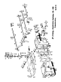
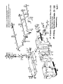
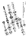
- 1 ZF Synchroma Gearbox S 5-325
Assembly, Maintenance and Operation
Contents
I.
Technical data
II.
Description
III. Operation
IV.
Maintenance
V.
Tools
VI.
Dismounting and checking individual members
VII. Assembly and operational check
VIII. Ordering of spare parts
IX.
Key to illustrations and exploded view
X.
Service stations
I. Technical data
max. input torque: 44 mkg (317 ft.lb.)
- 2 Ratios:
1st speed
2.73
2nd speed
1.76
3rd speed
1.23
4th speed
1.0
5th speed
0.83
reverse
3.31
speedometer
1.75
1st to 5th gear synchro mesh; reverse with sliding gear
Weight of gearbox:
approx. 56 kg (123 lb)
Oil capacity:
approx. 2.0 litres (3.5 pints)
V.
Tools
Tool .1.
Bench cradle Tool No.
Tool .2.
Bearing replacer for front taper roller bearing (307) on
layshaft. Tool No. 1248 898 051
Tool .3.
Bearing replacer for rear taper roller bearing (304)
layshaft. Tool No. 1248 898 052
on
- 3 Tool .4.
Guide bush for synchronizer body (1st and 2nd gear).
Tool No. 1211 898 001
Tool .5.
Replacer for roller bearing inner rings, bearing
bush
(436), sleeve carrier (438) and speedometer worm (442)
on input shaft. Tool No. 1248 898 053
Tool .6.
2 distance pieces for protecting the synchronizer rings
during replacement of input shaft. Tool No. 1248 898 101
Tool .7.
Remover (main tool used in conjunction with tools .10.
to .17. Tool No. 1248 898 201
Tool .8.
Input shaft remover. Tool No. 1248 898 204
Tool .9.
Yoke for removing clutch body from input shaft, when
latter is pulled out of the housing with tool .8. Tool
No. 1248 898 351
Tool .10. Adaptor set for removing speedometer worm (442). Tool
No. 1248 898 202
Tool .11. Adaptor set for removing the sleeve carrier (438). Tool
No. 1248 698 206
- 4 Tool .12. Adaptor set for removing the needle bearing rings (436).
Tool No, 1248 898 906
Tool .13. Adaptor set for removing 1st speed gear (424) from main
shaft. Tool No. 1248 898 207.
Tool 14,. Thread protector for main shaft (414). Tool No. 1248 898
054
Tool .15. Adaptor set for removing the rear taper roller bearing
(304) from the layshaft. (305). Tool No. 1248 898 209
Tool .16. Adaptor set for removing the front taper roller bearing
(307) from the layshaft. Tool No. 1248 896 208
Tool .17. Adaptor set for removing the helical gear 5th speed
(302) from the layshaft. Tool No, 1248 898 205
Tool .18. Remover for reverse shaft (503). Tool No, 1248 898 206
- 5 VI. Dismantling
Fig. 1
1. Removal of gearshift mechanism
Place gearbox into bench cradle .1. and push selector forks into
neutral.
After unscrewing bolts (704) remove gearbox cover (707) from
housing. (Fig. 1).
Unscrew 2 swivel bolts (116) and remove 5th gear selector fork
(634).
Fi g. 2.
2. Removal of main shaft and input shaft
After loosening screw (809) remove speedometer drive. Engage two
gears, remove tab washer (444) on output flange (443) and hexagon
screw (445) and withdraw flange.
Unscrew hexagon bolts (109 and 112) and nuts (105) of end housing
(111). (Fig. 2). Remove one of the two set screws (107) so that
the housing can be shifted slightly and then removed.
- 6 Fig. 3.
Release circlip (440) and remove speedometer worm (442) from
output shaft, using tool .7. and adaptor set 9109 (Fig. 3).
Release second circlip (440).
Fig. 4.
Remove distance bush (441) and release third circlip (440) on 5th
speed gear. Using main tool .7. and adaptor set .11., withdraw
complete 5th speed gear synchronizer body (406), placing remover
on sleeve carrier (438) (Fig. 4). Remove main shaft key (416) and
withdraw 5th speed gear (437) together with needle cage
(413).
Fig. 5.
Withdraw bearing bush (436) from shaft, using main tool .7. and
adaptor set .12. (Fig. 5) and remove, thrust washer (435).
Fig. 6.
Release circlip (301) and withdraw 5th speed layshaft gear(302),
using main tool .7. and adaptor set .17. Loosen screws (110) and
- 7 remove Intermediate plate (104). Unbend looking
piece(429),
engage two gears and unscrew look nut (430) with a
commercial hook spanner. (Fig. 6). Remove look nut (201) on input
shaft (205) in the same manner.
Fig. 7.
Put sliding sleeves into neutral and place tool .9. between
housing wall and 4th speed clutch body (on input shaft). Withdraw
Input shaft with the aid of tool .8. (Fig. 7).
Press
bell bearing (202) and roller bearing (204) from input shaft and
remove needle bearing (401) from end of main shaft.
Using a
rubber hammer, drive the main shaft with light blows 2 - 3 mm
towards the input side and remove the ball bearing (426)
Fig. 8.
Lift the main shaft and all its components with input side first,
in a slanting position out of the housing (Fig. 8).
- 8 Fig. 9.
Fig. 10.
3. Removal of layshaft and reverse
With a soft drift drive the layshaft towards the rear until roller
bearing (304) on input aide is free of the housing. Remove inner
ring of roller bearing (304) with main tool .7. and adaptor set
.15. (Fig. 9). Take the layshaft, with the large gear wheel first,
out of the gearbox housing (Fig. 10). Remove front roller bearing
(307) from the shaft, using main tool .7. and adaptor set .16.
(Fig. 11). Release circlip (306). Withdraw reverse shaft (503)
with tool .18. and remove reverse gear (501) and thrust washer
(502).
Fig, 11.
Fig. 12.
4. Dismantling the main shaft
Clamp main shaft at splined section vertical in a vice with soft
- 9 jaws. Release circlip (410) on sleeve carrier. Remove sliding
sleeve (402) together with synchronizer components and sleeve
carrier (411). Withdraw 3rd speed gear (412) (Fig. 12) and both
needle
bearings (413) from shaft. Take main shaft out of vice.
Fig. 13
Remove 1st speed gear (424), using tool .7. together with adaptor
set .13. and thread protector .14. (Fig. 13). Lift the 2 needle
cages (413) over the splined section and
(423) together with the synchronizer
remove reverse spur gear
components, taking care not
to lose the key (415).
Remove 2nd speed gear (418) and split needle bearing (417).
Fig. 14.
5. Disassemble the synchronizer components.
Press spur gear (423) respectively sliding sleeve (402) from
synchronizer body (422) or (406), taking care not to lose the 6
balls (409) and the 4 springs (497 and 408), which are liable
- 10 to jump out. It would be advisable to cover these components with
a cloth, so that they cannot got lost.
Release circlips (403) and remove synchronizer rings (404 and 421)
and the locking Pawls (405) (Fig. 14).
Fig. 15.
6. Dismantling cover and gearshift mechanism
Unscrew hexagon nuts (615) and remove selector tower (612) and
selector lever (607). Remove reversing light switch. Remove all
cover plates (702). Loosen all grub screws (617)
on
the selector forks and drivers (Fig. 15) and knock out the
selector bars from the rear (selector tower).
Remove detent pins (621), compression springs (622) and balls
(620). Remove slide bars (601), detent pins (602 and compression
springs (603) from housing cover.
Remove shaft seal (120), circlip (119) and needle bearing (118)
from end housing (111) and take all seal rings and shims out of
- 11 housing and cover.
Checking the individual components
Test synchronizer rings (404 and 421) for wear. If the rings
are
worn, they must be exchanged for new ones.
Test teeth of clutch body for wear and damage. All selector forks
must be tested for wear, if bent they should be renewed and not
straightened out. Test locking pawls, stop bolts, balls and
selector bar (635) for wear. Test ball and roller bearings for
wear.
The contact surfaces of the needle bearings and the needles
themselves should not show any signs of wear, Input shaft
and
clutch body can only be exchanged as a complete unit as the
clutch
body is ground when mounted on the shaft. Input shaft
and clutch body are each punch-marked.
Check output flange (443) for running-in defects of the shaft seal
(120) and the needle bearing (118).
- 12 It the housing, intermediate plate, or end housing have been
damaged due to improper handling, they must be exchanged jointly.
VII. Assembly of the gearbox S 5-325
All components must be thoroughly cleaned before the gearbox is
assembled. Any residues of paint on the joint faces of housing and
cover must always be removed. Each component must be tested for
wear or other defects and must be well greased before they are
assembled. Seal rings, joints and tab washers must be renewed.
Special care should be taken that no chips or other foreign matter
remain inside the housing.
Always use a soft hammer (rubber, plastic, etc.), for driving home
shafts and bolts; never use a steel hammer direct on gearbox
components.
Assemble the individual shafts and the complete gearbox in
- 13 reverse order to the dismantling instructions, Gear wheels with
collars on one side must be correctly positioned during the
assembly.
A. Assembly of reverse
Clamp gearbox into bench cradle .1.
Drive the reverse shaft (503), with small diameter first, into the
bore of the housing (101) until thrust washer (502 ) and the
reverse gear (501) can be mounted. The groove for the selector
fork on the reverse shaft must point towards output side. Place
second thrust washer in position and drive the reverse shaft into
the housing (Fig. 16). Make sure that the milled face of the
reverse shaft is in oorrect position so that the intermediate
Plate (104) can be flanged to the housing.
Fig. 16.
B. Assembly and installation of layshaft
Insert circlip (306) and press the small roller bearing (307) on
input end of layshaft (305), using bearing replacer .2. (Fig. 17).
- 14 Guide layshaft with input end first, in a slanting position into
the housing (Fig. 10). With the aid of bearing replacer .3. press
the rear roller bearing (304) on the shaft (Fig. 18).
Drive outer
bearing rings of front and rear roller bearings into the housing,
using a soft hammer.
Fig. 17.
Fig. 18.
C. Pre-assemble synchronizer
Fig. 19.
a)
3rd and 4th gear synchronizer body
1.
Place synchronizer rings (404), offset against each other by
90° on the synchronizer body and place circlips (403) in
position. Make sure that the synchronizer rings can turn
easily. The position of synchronizer rings to synchronizer
body is optional.
Place the 4 locking pawls (405) into the recesses of the
- 15 synchronizer rings so that the inner conical point of the pawl
points towards the centre of the synchronizer body (Fig. 19).
Fig. 20.
2.
Place the two longer compression springs (407) into the blind
holes of the synchronizer body and attach one ball (400) with
some grease to each compression spring. Before the sliding
sleeve (402) is mounted the following points must receive
consideration:
Four times two adjacent tooth of the sliding sleeve are
designed as locking teeth, which during the synchronizing
process press the pawls upwards. The sliding sleeve must be
placed over the pre-assembled synchronizer body so that one
pawl will always lie between the two locking teeth. (Fig.
20).
Moreover, the looking teeth must lie behind the pawl; as
- 16 viewed when the pre-assembled synchronizer body is lying in a
horizontal position on a plate.
The 2 pawls, which are enclosed, respectively carried along
by the upper synchronizer ring, must lie above the locking
teeth. (Locking teeth therefore in lower half of sliding
sleeve).
The two other pawls, which are carried along by the lower
synchronizer ring, lie below the locking teeth. (Locking
teeth therefore in upper half of sliding sleeve).
It is also most important that the teeth of the sliding
sleeve, which are chamfered at both ends, always lie over the
balls, in order to prevent the balls from binding when the
gears are disengaged. When the sliding sleeve has been
mounted incorrectly (upside down), the chamfered teeth are
lying next to the balls and not over the balls.
3.
From the inside, place into each of the 2 through bores of
- 17 the synchronizer body one ball (409), one compression spring
(408) (these are 0.7 mm shorter than those in the blind
holes)
and then attach another ball with some grease. Push
sleeve carrier (411) into the bore of the synchronizer body,
taking care that the two balls are pressed into the bore.
b) 1st and 2nd gear synchronizer body
The synchronizer for the 1st and 2nd gear is assembled as
described above, with the exception that in place of the sliding
sleeve (402) the spur gear (423) is pushed over the synchronizer
body (422). A sleeve carrier is not necessary as the synchronizer
body in placed direct on the main shaft (414).
c) The 5th gear synchronizer is only required to operate in one
direction, its design, however, is similar to the 3rd and 4th gear
synchronizer.
The stops of the sleeve carrier (438), which is used with this
synchronizer must rest against the synchronizer body on the
- 18 opposite side of the synchronizer ring (404) when the sleeve
carrier is placed in position. In place of the second synchronizer
ring a disc (439) is used, and this is secured with a circlip
(403).
D. Assembly of main shaft
Fig. 21
Clamp main shaft (414), with long splines pointing upwards, in a
vice. (Use lead jaws).
Secure the two special split bearings (417) with some grease to
the sliding surface of the shaft (above collar). Push the 2nd
speed spur gear (417) over the two split bearings so that the
conical end points towards output side (facing upwards).
Place thrust washer (419) on helical gear so that the two oil
grooves are facing downwards. (Fig. 21).
Fig. 22
Turn the thrust washer so that the milled slot on one of the
internal splines of the thrust washer is in line with the keyway
- 19 on one of the main shaft splines. Place the key with some grease
into the keyway of the shaft spline as shown in Fig. 22. The small
and of the key must fit into the recess out into
the thrust washer (419).
Fig. 23.
Place pre-assembled 1st and 2nd gear synchronizer and spur gear on
the main shaft, using guide bush .4. (Fig. 23). This guide bush
presses the inner balls (409) previously placed in the through
bores of the synchronizer body outwards. Under no circumstances
should the balls rest against the shaft key (415). Gear teeth of
spur gear must face upwards, towards output side. Mount the 2
needle bearings (413) and the 1st speed gear (conical surface
towards synchronizer). Place thrust washer (425) with oil grooves
on the gear. Using bearing replacer .5. press one half of the
bearing inner ring (ball bearing 426) on the main shaft. Clamp
main shaft in a vice so that the long splines face downwards.
- 20 Mount 2 needle cages (413 ) and 3rd speed gear (412 ) with cone
towards input side. Press pre-assembled 3rd and 4th gear
synchronizer on shaft so that inner recess of the sleeve carrier
(411) face upwards. (Fig. 24).
Place circlip (410) in
position.
Check synchronizer clearance of 1st to 5th gear with feeler gauge.
The clearance should be 0.6 - 1 mm. If the clearance in too
great
a new synchronizer ring (404 or 421) must be installed; if the
clearance is too fine, the synchronizer ring must be machined
accordingly.
Engage 3rd speed gear.
Fig. 24
E. Installation of main shaft
The marked position of input shaft and clutch body must also be
clearly marked on the outer teeth.
Place clutch body with cone end into the 4th gear synchronizer
ring.
- 21 Guide the pre-assembled main shaft in a slanting position and with
the output side first Into the housing. (Fig. 8). (Fig 25). Press
ball bearing (426) together with circlip into the
housing and then press the second half of the bearing inner ring
on the shaft, using bearing replacer .5. Mount locking ring (429)
and tighten lock nut (430) with lock nut key. (Engage two gears).
Secure look nut.
F. Mount input shaft
Place circlip (203) into the radial groove of roller bearing
(204).
Press first the roller bearing and than the ball bearing
(202) on
the input shaft (205).
Screw on lock nut (201). Place needle bearing (401) on end of main
shaft and push the input shaft through the housing bore.
In order to protect the synchronizer rings (404), place one
distance piece .6. in front and the other behind the sliding
- 22 sleeve. (Fig 26).
Fig. 26.
With the aid of a soft hammer drive the input shaft according to
the position markings into the internal teth of the clutch body.
Tighten lock nut (201) with commercial lock nut spanner and secure
by driving the locking ring into the longitudinal groove of the
input shaft.
Push oil collector pipe (115) from input side into the housing
bore. (The open side of the bisected pipe points upwards and
inside).
G. Mount Intermediate Plate
Fig. 27.
Drive the layshaft towards input side until the front bearing
(307) is flush with the joint face of the housing. Push home outer
ring of rear roller bearing (304).
Measure distance from outer ring of rear bearing to joint face
- 23 of housing, and also measure the depth of the respective recess in
the intermediate plate (104). For this purpose the joint (102)
must be placed on the intermediate plate. The
difference between
both measurements plus the initial stress of 0.03 - 0.05 mm will
be the thickness of the shims (303) which are placed in the recess
of the intermediate plate). The shims are available in sizes 0.05,
0.1, 0.2, 0.5 and 1.0 mm.
Fig. 28.
Push ball bearing (426) into the housing until the circlip (427)
abuts. Determine thickness of shims (428) in a similar manner as
for the roller bearing of the layshaft. Since in this case the
distance of a ball bearing has to be adjusted, the initial stress
of 0.03 - 0.05 mm is omitted. (Figs. 27 and 28).
The shims are also placed in the recess of the intermediate plate.
They are available in sizes 0.1 and 0.15 mm. Again check 4th gear
synchronizer clearance and if necessary adjust. Attach Joint (102)
- 24 with some grease to the intermediate plate. Place intermediate
plate with the inserted shims on the gearbox housing, tighten the
8 screws (110) and secure with tab washers (108). Knock set pins
(103), which are used for centering the end housing, into the
bores of the intermediate plate.
H. Mount 5th speed gear
Fig. 29.
Press the layshaft gear (302), with the cylindrical recess first,
on the shaft, (Fig. 29) and insert circlip (301).
Fig. 30.
Place thrust washer (435), with oil grooves towards output side,
against lock nut (430) and press bush (436) on the main shaft,
using tool .5. Slide needle bearing (413) and 5th
speed helical gear (437) over bush (436) so that the conical rim
faces towards the output side. With the aid of a soft hammer drive
two Woodruff keys (416) into the main shaft. Mount pre-assembled
- 25 synchronizer body (synchronizer ring facing towards 5th speed
gear), using tool .5. (Fig. 30). Projection on sleeve carrier
facing towards output side.
Place circlip (440) into radial groove behind the sleeve carrier.
Slide distance bush (441) over the main shaft and place 2nd
circlip (440) in position. With tool .5., press speedometer worm
(442) on the shaft until it rests against the 2nd circlip and
secure it with the 3rd circlip.
I. Mount end housing
Press needle bearing (118) into neck of end housing. Place circlip
(119) in position and press in shaft seal (120) until it rests
against the circlip. (Lip of seal ring towards outside).
Insert one set screw (107) into the thread of the
intermediate
plate and the other set screw into the long bore of the end
housing. Push the end housing over the main shaft and move it
about until the set screw sitting in the bore of the end
housing
- 26 can also be screwed into the thread of the intermediate plate.
Secure end housing with screws (109 and 112) and the 2 hexagon
nuts (105). Place spring washers (106) below the screws (112) and
below the nuts (105). The two screws (109) are secured with tab
washers (108). Push output flange (443) on the splined
section of
the main shaft and secure with hexagon screw (445) and tab washer.
Fit speedometer drive and secure with hexagon screw (809) and tab
washer (808). Place the two sliding pieces (635) into the bores of
the 5th speed selector bracket (634).
Fig. 31.
Guide the pre-assembled selector bracket into the 5th gear sliding
sleeve (402) so that the selector finger engages the 5th gear
selector bar (Fig. 31) and the swivel bolt (116) with the seal
rings (117) can be screwed in. Check selector fork for ease of
operation.
- 27 K. Assembly of selector mechanism and housing cover
Place the housing cover (701) on a bench so that the surface which
will be joined to the housing faces upwards. Push slide (601),
with stop notch upwards, into the transverse bore in the selector
tower.
Place 5th speed selector bar (636) (short bar with lug on its end)
into the outer bore of the centre cross piece and
compression
spring (622) and bolt (21) into the bottom bore. Press the
selector bar past the detent and push it along until the spring
(637a) and the driver (637) can be fitted, screw the grub screw
through the driver and into the bore of the selector fork. Put
selector bar into neutral. Guide the longest of the 4 selector
bars (19) through the bore for the reverse light switch until the
reverse gear driver (623) can be fitted before the bar has reached
the first cross piece, Push the selector bar up to the centre
cross piece, place compression spring (622) and bolt (21) into
- 28 the bottom bore of the centre cross piece and then press the
selector bar past the detent. Fit selector fork (618) and push the
selector bar through until the bolt can slide into the
slot provided for this purpose. Screw grub screw (617) through the
driver (623) respectively through the selector fork (618) and
into the bores of the selector bar. Put selector bar into neutral.
Place two balls into the transverse bore in the centre cross piece
between the reverse selector bar and the 1st and 2nd speed
selector bar. Guide 1st and 2nd speed selector bar
(629) (bar with recess for 5th speed selector bracket) into the
bore next to the reverse gear selector bar. Fit driver (630) and
place spring (622) and bolt (621) into the bottom bore in the
centre cross piece. Push selector bar through and secure selector
fork (628) and driver with grub screws. Put selector bar into
neutral.
- 29 Place two balls into the transverse bore in the centre cross piece
between the 5th speed selector bar and the 3rd and 4th speed
selector bars.
Place also two balls between 1st and 2nd speed selector bar and
3rd and 4th speed selector bar. Fit 3rd and 4th speed selector bar
(632). The 3rd and 4th speed selector bar must be pushed through
the bore of the lug on the selector bar (5th speed) and
through the reverse selector fork,
Turn the housing cover so that it rests on the selector
forks.
Place bolt (606) from the outside into the bore of the ball socket
(604).
Place the bell socket into the recess of the cover so that the
threaded pin can be screwed through the threaded bore in the cover
and into the hollow of the ball socket.
Place the complete gearshift lover (607) into the ball socket.
Fit spring (608), washer (609), rubber gasket (
) and spring
- 30 washer (610) to ball end.
Place bolt (602) and spring (603) into the bore of the gearshift
cover.
Guide gasket (611) and selector tower (612) over the threaded pins
(613) and secure with nuts (615) and spring washers (614). Pull
rubber grommet (616) over the selector tower and screw on selector
lever knob.
L. Connect pre-assembled housing cover to gearbox housing
Put selector sleeves and reverse gear into neutral.
Make sure that the selector forks are also in neutral.
Place housing cover on gearbox housing, making sure that all
selector forks engage with the sliding sleeves and that the fork
for reverse engages with the bolt of the 5th speed selector
bracket (Fig. 32). Secure cover with screws (704) and spring
washers (703).
Fit magnetic plug (113) and oil dip stick (114).
- 31 Fig. 32
Operational check
Engage all gears successively. During this procedure turn the
input shaft and check that the output flange is carried along in
each gear. During the engagement of 1st and 2nd gear and also
during the engagement of the 5th gear a detent must be overcome.
For the engagement of the reverse gear the gearshift lever must be
lifted upwards.
Checking neutral position of reverse gear:
For this purpose the gearbox must be lifted at the input shaft and
the 2nd speed gear must be engaged. Check whether the reverse gear
scrapes against the reverse spur gear (423) when the input shaft
is turned. If this is the case, nut (627) must be unscrewed and
the eccentric pin (624) must be adjusted.
The reverse gear operating lever (625) must be adjusted so that
- 32 the reverse gear does not scrape against the reverse spur gear and
the gearshift lever does not bind in neutral.
VIII. Order for spare parts
In order to achieve a speedy and correct delivery of spare parts,
orders should contain the following details:
1.
Gearbox type - S 5-325
2.
Gearbox No. - this is stamped on the type plate on the
gearbox housing cover
3.
Designation of required spare parts: Name the spare part
exactly an given in the spare parts list and instruction
manual
4.
Part No. This is the 10 digit number stamped on or cast in
the spare part to be replaced
5,
If one or several indications of point 1 - 4 cannot be given
the following details are important:
a) Reference No. given in the instruction manual
- 33 b) Make and type of vehicle and name of firm, which
manufactured the chassis.
6.
Method of dispatch: by post, freight, express, etc.,
otherwise the method of dispatch will be left to our
discretion.
A clearly expressed order is as follows:
I hereby order for gearbox S 5-325, gearbox No. 135
1 complete input shaft
1248 202 900
consisting of:
complete input shaft
clutch body
1248 202 006
1248 302 007
Dispatch immediately by express.
Orders made by telephone or telegraph must be confirmed in
writing. Dispatch is made at Purchaser’s risk, even if no charge
is made for the spare parts. Spare parts are only supplied free of
charge during the guarantee period, provided that on examining the
part, it is found that the damage was due to faulty manufacture or
- 34 defective material. For this reason the faulty part must be
returned to us for testing without having been tampered with and
all carriage paid. Faulty samples will be scrapped unless their
return is especially requested when they are sent to us.
Terms of payment: Cash on delivery.