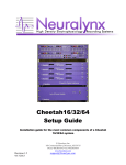
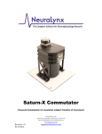
1
HS-XX-Stim Headstage which allows simultaneous stimulation and recording on electrodes. Neuralynx, Inc. 105 Commercial Drive, Bozeman, MT 59715 Phone 406.585.4542 • Fax 866.585.1743 www.Neuralynx.com Revision 1.5 6/6/2013 [email protected] Table of Contents 1 2 3 Document Overview ................................................................................................... 5 HS-XX-Stim Overview ............................................................................................... 5 What parts are needed to use the HS-XX-Stim? ......................................................... 6 3.1 HS-36-Stim........................................................................................................... 6 3.2 HS-18-Stim........................................................................................................... 6 3.3 HS-18-MM-Stim .................................................................................................. 7 3.4 Electrostatic Sensitive Equipment ........................................................................ 7 4 Installing the Digital Lynx SX Firmware Update ....................................................... 8 5 Installing the Software ................................................................................................ 8 5.1 Instructions ........................................................................................................... 8 6 Quick Start ................................................................................................................ 11 6.1 HS-XX-Stim Setup............................................................................................. 11 6.2 Software ............................................................................................................. 12 6.2.1 Boot Cheetah and HS-XX-Stim Control Software ..................................... 12 6.2.2 Connect to Cheetah ..................................................................................... 12 6.2.3 Load Provided Configuration File .............................................................. 13 6.2.4 Configure HS-XX-Stim .............................................................................. 14 7 Hardware Overview .................................................................................................. 17 7.1 HS-XX-Stim Switches ....................................................................................... 17 7.2 HS-XX-Stim Communication ............................................................................ 17 7.3 Extra Hardware Connections ............................................................................. 17 7.4 HS-XX-Stim Power............................................................................................ 18 7.5 Overdriving the HS-XX-Stim Stimulation Voltage ........................................... 19 8 Software Overview ................................................................................................... 20 8.1 Device Address .................................................................................................. 21 8.1.1 Instructions .................................................................................................. 21 8.2 Reset ................................................................................................................... 22 8.2.1 Instructions .................................................................................................. 22 8.2.2 Command Description ................................................................................ 22 8.3 Switch Configuration ......................................................................................... 23 8.3.1 Instructions .................................................................................................. 23 8.3.2 Command Description ................................................................................ 24 8.4 Pause Time ......................................................................................................... 25 8.4.1 Instructions .................................................................................................. 25 8.4.2 Command Description ................................................................................ 25 8.5 Pattern Configuration ......................................................................................... 26 8.5.1 Instructions .................................................................................................. 26 8.5.2 Command Description ................................................................................ 27 8.6 Run ..................................................................................................................... 28 8.6.1 Instructions .................................................................................................. 29 8.6.2 Command Description ................................................................................ 29 8.7 Stop..................................................................................................................... 29 8.7.1 Instructions .................................................................................................. 29 8.7.2 Command Description ................................................................................ 29 Revision 1.5 HS-XX-Stim Users Manual 6/6/2013 Page 2 8.8 Change Address.................................................................................................. 30 8.8.1 Instructions .................................................................................................. 30 8.8.2 Command Description ................................................................................ 30 8.9 Command List .................................................................................................... 31 8.10 File > Load/Save Configuration ..................................................................... 31 8.11 Connection > Connect to Cheetah .................................................................. 32 8.12 Software Speed > Fast/Slow Mode ................................................................ 32 9 Software Operating Modes ....................................................................................... 34 9.1 Direct Control Operation.................................................................................... 34 9.1.1 Description .................................................................................................. 34 9.1.2 Instructions .................................................................................................. 34 9.2 Configuration File Operation ............................................................................. 35 9.2.1 Description .................................................................................................. 35 9.2.2 Instructions .................................................................................................. 35 9.3 Real Time Operation Example ........................................................................... 36 9.3.1 Description .................................................................................................. 36 9.3.2 Instructions .................................................................................................. 36 10 Glossary .................................................................................................................... 38 List of Figures and Tables Figure 3-1 HS-XX-Stim and Components .......................................................................... 6 Figure 3-2 HS-36-Stim ....................................................................................................... 6 Figure 3-3 HS-18-Stim ....................................................................................................... 6 Figure 3-4 HS-18-MM-Stim ............................................................................................... 7 Figure 5-1 MATLAB Compiler Run Time Installer Splash Screen ................................... 8 Figure 5-2 MATLAB Compiler Run Time License Agreement ........................................ 9 Figure 5-3 MATLAB Compiler Run Time Confirmation Page ......................................... 9 Figure 5-4 MATLAB Compiler Run Time Installing....................................................... 10 Figure 5-5 HS-XX-Stim Control Software ....................................................................... 10 Figure 6-1 Hardware Connections .................................................................................... 11 Figure 6-2 HS-XX-Stim Control Software ....................................................................... 12 Figure 6-3 Connect to Cheetah ......................................................................................... 13 Figure 6-4 Disconnect from Cheetah ................................................................................ 13 Figure 6-5 File > Load Configuration............................................................................... 13 Figure 6-6 Command List Containing Save Commands .................................................. 13 Figure 6-7 Log File ........................................................................................................... 14 Figure 6-8 Command List Containing a Run Command .................................................. 14 Figure 6-9 HS-36-Stim Sequence ..................................................................................... 15 Figure 6-10 HS-18-Stim/HS-18-MM-Stim Sequence ...................................................... 15 Figure 6-11 Command List Containing a Stop Command ............................................... 16 Figure 6-12 Command List Containing a Reset Command .............................................. 16 Figure 7-1 HS-XX-Stim Switches .................................................................................... 17 Figure 7-2 External Stimulation Connections................................................................... 18 Figure 7-3 2-Pin BNC Pinout Connections ...................................................................... 18 Figure 7-4 SetPersistentHSPowerEnabled added to Cheetah.cfg ..................................... 18 Revision 1.5 HS-XX-Stim Users Manual 6/6/2013 Page 3 Figure 7-5 SetPersistentHSPowerEnabled Command Syntax .......................................... 19 Figure 7-6 Overdriving the HS-XX-Stim ......................................................................... 19 Figure 8-1 Software Sections ............................................................................................ 20 Figure 8-2 Software Workflow ......................................................................................... 21 Figure 8-3 Device Address ............................................................................................... 21 Figure 8-4 Reset ................................................................................................................ 22 Figure 8-5 Switch Configuration ...................................................................................... 23 Figure 8-6 Switch Configuration Illustration .................................................................... 24 Figure 8-7 Pause Time ...................................................................................................... 25 Figure 8-8 Pattern Configuration ...................................................................................... 26 Figure 8-9 Style 2 Pattern Configuration .......................................................................... 27 Figure 8-10 Style 3 Pattern Configuration ........................................................................ 28 Figure 8-11 Style 4 Pattern Configuration ........................................................................ 28 Figure 8-12 Run ................................................................................................................ 28 Figure 8-13 Stop ............................................................................................................... 29 Figure 8-14 Change Address ............................................................................................ 30 Figure 8-15 Command List ............................................................................................... 31 Figure 8-16 File > Save Configuration ............................................................................. 31 Figure 8-17 File > Load Configuration............................................................................. 32 Figure 8-18 Connect to Cheetah ....................................................................................... 32 Figure 8-19 Fast Mode ...................................................................................................... 32 Figure 8-20 Fast Mode HS-Stim Log File ........................................................................ 32 Figure 8-21 Slow Mode .................................................................................................... 33 Figure 8-22 Slow Mode HS-Stim Log File....................................................................... 33 Figure 9-1 Direct Control Operation Work Flow ............................................................. 34 Figure 9-2 Configuration File Operation Work Flow ....................................................... 35 Figure 9-3 Real Time Operation Work Flow .................................................................... 36 Revision 1.5 6/6/2013 HS-XX-Stim Users Manual Page 4 Document Overview This document describes the specifications and features of the HS-XX-Stim. It also explains how to setup your headstage, test it, and use it during normal operation. There is a glossary at the end of the document. 1 HS-XX-Stim Overview This HS-XX-Stim is a headstage that not only records from electrodes but also allows stimulation of electrodes. Each input on the HS-XX-Stim, up to 36 electrode connections, has two individual switches attached to it. This allows for monopolar and bipolar stimulation protocols (ie. stimulation can be delivered from any electrode to a reference, Panel Ground, or between any number of electrodes). Features: • Versions include HS-36-Stim, HS-18-Stim, and HS-18-MM-Stim. • Exact same Low Noise Unity Gain Amplifiers (G = 1.0) as pervious headstages. • High Common Mode Rejection Ratio(CMRR). • Two Individual Switches connected to each electrode. • One Master Control Switch for each stimulation source. • Two-Way Communication between HS-XX-Stim Processor and Digital Lynx SX. • Command Builder Software provided. • Download Custom Switch Configurations and Patterns. • Stimulation times down to 400µs with 100µs resolution. • Up to 50mA per channel(±5V Max). Subject Safety and Data Integrity will be lost if exceeded. Refer to Section 6.5 Overdriving the HS-XX-Stim Stimulation Voltage. • 21Ω Typical Switch On Resistance. • NetCom Controllable. • Compatible with Neuralynx EIBs and Versa Drives. • Compatible with Digital Lynx SX systems. Revision 1.5 6/6/2013 HS-XX-Stim Users Manual Page 5 2 What parts are needed to use the HS-XX-Stim? The HS-XX-Stim requires the following items for use with the Digital Lynx SX and external stimulus device: 1. HS-XX-Stim, various models described in following sections 2. HS-XX-Stim Interface Board 3. Ribbon Cable Specific to SX 4. HS-XX-Stim Test Board 5. Two, 2-Pin BNCs 6. Blue Jumper Figure 2-1 HS-XX-Stim and Components If any item is missing or appears to be damaged please contact Neuralynx Support. 2.1 HS-36-Stim • • • • • • 32 AD Channels Unity Gain Amplification. 4 References Unity Gain Amplification. 2 Switches connected to each AD Channel and Reference. Master Control Switch for each Stimulation Source. Compatible with HS-36 Series EIBs. 4.0 grams. Figure 2-2 HS-36-Stim 2.2 HS-18-Stim • • • • • • 16 AD Channels Unity Gain Amplification. 1 Reference Unity Gain Amplification. 2 Switches connected to each AD Channel and Reference. Master Control Switch for each Stimulation Source. Compatible with HS-18 Series EIBs. 4.3 grams. Revision 1.5 6/6/2013 Figure 2-3 HS-18-Stim HS-XX-Stim Users Manual Page 6 2.3 HS-18-MM-Stim • • • • • • 16 AD Channels Unity Gain Amplification. 1 Reference Unity Gain Amplification. 2 Switches connected to each AD Channel and Reference. Master Control Switch for each Stimulation Source. Compatible with Versa Drives. 4.3 grams. Figure 2-4 HS-18-MM-Stim 2.4 Electrostatic Sensitive Equipment All Neuralynx Equipment is Electrostatic Sensitive and should be handled with appropriate measures. Always wear a static strap and use all appropriate ESD measures when handling any electronics. Please contact Neuralynx for detailed information if you have questions. Revision 1.5 6/6/2013 HS-XX-Stim Users Manual Page 7 3 Installing the Digital Lynx SX Firmware Update Digital Lynx SX Firmware Update Version 1.20 is required to use the HS-XX-Stim. The Firmware package can be downloaded from the Neuralynx Website: www.Neuralynx.com > Software > Drivers and Firmware> Digital Lynx SX Firmware Update Version 1.20 Instructions for installing the Firmware Update are contained in the download package. 4 Installing the Software The HS-XX-Stim Control Software is compiled using the MATLAB Compiler Run Time. Because of this the MATLAB Compiler Run Time must be installed on your system once to use the software. A Package is provided by Neuralynx. Package contains the MATLAB Compiler Run Time, the Executable, and some additional files. The HS-XXStim Control Software can be installed and run on the same PC as Cheetah or on another network PC. 4.1 Instructions 1. Save the HS_XX_Stim_Control_pkg.exe file to a folder named "HS-XX-Stim Control Software" on the Desktop. 2. Open HS_XX_Stim_Control_pkg.exe, if the Operating System asks for permission to open the file, allow it. Files will be extracted and saved in the folder. This may take several minutes. 3. The MATLAB Compiler Run Time Installer Splash Screen will appear. Figure 4-1 MATLAB Compiler Run Time Installer Splash Screen 4. Select Next > to proceed to the License Agreement. Revision 1.5 6/6/2013 HS-XX-Stim Users Manual Page 8 Figure 4-2 MATLAB Compiler Run Time License Agreement 5. When you have finished reading the License Agreement select Yes then Next >. 6. The next page is the Confirmation Page. Select Install >. Figure 4-3 MATLAB Compiler Run Time Confirmation Page 7. The MATLAB Compiler Run Time will now begin installing. This may take up to 15 minutes to complete. Revision 1.5 6/6/2013 HS-XX-Stim Users Manual Page 9 Figure 4-4 MATLAB Compiler Run Time Installing 8. Once the MATLAB Compiler Run Time is finished installing select Finish. 9. Installation is now complete. Open HS_XX_Stim_Control.exe. The HS-XX-Stim Control Software will boot and is ready to be used. Figure 4-5 HS-XX-Stim Control Software Revision 1.5 6/6/2013 HS-XX-Stim Users Manual Page 10 5 Quick Start The following instructions are provided to quickly setup and test your HS-XX-Stim setup. 5.1 HS-XX-Stim Setup Although the HS-XX-Stim connects to a Digital Lynx SX just like a standard Neuralynx Headstage there are some additional connections that need to be made. A Control Cable is provided for connecting the Digital Lynx SX Serial Device Expansion Port to the Global Reference Module on the DRS-36 Board. This cable also provides access to Stim 2 Source, Stim 2 Return, and Panel Ground for connecting to external Stimulation Sources. The HS-XX-Stim connections are illustrated and described below. Figure 5-1 Hardware Connections Connections: 1. Connect the HS-XX-Stim to a DRS Board on the Digital Lynx SX. a. HS-36-Stim: This requires a TETH-HS-36 and an ADPT-HS-36-DRS. b. HS-18-Stim/HS-18-MM-Stim: This requires an ADPT-HS-27-ERP-27. 2. Connect the HS-XX-Stim Interface Board to the Serial Device Expansion Port on the Digital Lynx SX. 3. Connect the Blue Jumper, provided by Neuralynx, to J6 on the HS-XX-Stim Interface Board. This shorts +5V to Stim Source 2 and should be removed when finished with the Quick Start. Revision 1.5 HS-XX-Stim Users Manual 6/6/2013 Page 11 4. Connect the Ribbon Cable to the 10 pin connector on the HS-XX-Stim Interface Board. 5. Connect the other end of the Ribbon Cable to the 10 pin connector on the Global Reference Module. Note: The Ribbon Cable is a Daisy chain of up-to nine connectors. If you are using more than one HS-XX-Stim connect the ribbon cable to each Global Reference Module. 6. Connect the HS-XX-Stim to HS-XX-Stim Test Board. 5.2 Software 5.2.1 Boot Cheetah and HS-XX-Stim Control Software Power On the Digital Lynx SX and wait for boot cycle to complete. On the Desktop select the Run Cheetah shortcut to open the Cheetah Welcome Screen. Boot Cheetah with a configuration file for your setup. Browse to the Directory the HS-XX-Stim Control Software was installed in and select Neuralynx_HS_XX_Stim Control.exe. Figure 5-2 HS-XX-Stim Control Software 5.2.2 Connect to Cheetah The HS-XX-Stim Control Software must be connected to Cheetah through NetCom before configuring the Headstage. To connect to Cheetah select Cheetah Connection > Revision 1.5 HS-XX-Stim Users Manual 6/6/2013 Page 12 Connect to Cheetah, also described in Section 7.11 Connection > Connect to Cheetah. The HS-XX-Stim Control Software will connect to Cheetah using the Server Name listed in the Command List Section of the software, described in Section 7.9 Command List. Figure 5-3 Connect to Cheetah Once a connection has been established the pull down menu will change to Disconnect from Cheetah. Figure 5-4 Disconnect from Cheetah 5.2.3 Load Provided Configuration File A Configuration File is provided with the HS-XX-Stim Control Software for testing the Hardware. To load this Configuration File into the HS-XX-Stim Control Software select File > Load Configuration File, also described in Section 7.10 File > Load/Save Configuration. Figure 5-5 File > Load Configuration Depending on the HS-XX-Stim you are using browse to "HS-36-Stim Quickstart.cfg" or "HS-18-Stim Quickstart.cfg" in the HS-XX-Stim Control Software Folder on the Desktop and select Open. The Command List will populate with commands from the Configuration File. Revision 1.5 6/6/2013 Figure 5-6 Command List Containing Save Commands HS-XX-Stim Users Manual Page 13 The Command List now contains one Reset Command, four Save Switch Configuration Commands, one Save Pause Time Command, and one Save Pattern Configuration Command. 5.2.4 Configure HS-XX-Stim Once the Hardware is setup, the HS-XX-Stim Control Software is connected to Cheetah, the Configuration File has been loaded, and HS Power is Enabled(Cheetah is Acquiring) you can now configure the HS-XX-Stim. Select Output to Headstage and each command in the Command List will be sent to the HS-XX-Stim. Once all commands have been sent a log file called "HS-Stim Log File.txt" will open and display the results. It is overwritten each time Output to Headstage is selected. Figure 5-7 Log File You will notice that none of the LEDs on the HS-XX-Stim Test Board have illuminated. This is because the Configuration File only contained Save Commands. To initiate the saved pattern a Run Command needs to be sent to the HS-XX-Stim. Select Remove All to remove all the Save Commands from the Command List. In the Run Section of the HSXX-Stim Control Software select Run Pattern Style 4 Configuration 1 from the Switch Configuration of Pattern pull down menu and select Add Command. The Command List should now contain a single Run Command. Figure 5-8 Command List Containing a Run Command Select Output to Headstage and the Run Command in the Command List will be sent to the HS-XX-Stim. Once the HS-XX-Stim receives the Run Command it will immediately Revision 1.5 6/6/2013 HS-XX-Stim Users Manual Page 14 start illuminating the LEDs on the HS-XX-Stim Test Board. The sequence is illustrated below. Figure 5-9 HS-36-Stim Sequence Figure 5-10 HS-18-Stim/HS-18-MM-Stim Sequence Revision 1.5 6/6/2013 HS-XX-Stim Users Manual Page 15 The sequence will run indefinitely. A Stop Command can be sent to stop the sequence in its current configuration. Select Remove All to remove the Run Command from the Command List. In the Stop Section of the HS-XX-Stim Control Software select Add Command. The Command List should now contain a single Stop Command. Figure 5-11 Command List Containing a Stop Command Select Output to Headstage and the Stop Command in the Command List will be sent to the HS-XX-Stim. Once the HS-XX-Stim receives the Stop Command it will immediately stop the sequence in its current state, meaning some of the LEDs on the HS-XX-Stim Test Board will still be illuminated. A Reset Command can be sent to turn Off all the LEDs. In the Reset Section of the HS-XX-Stim Control Software select Add Command. The Command List should now contain a single Reset Command. Figure 5-12 Command List Containing a Reset Command Select Output to Headstage and the Reset Command in the Command List will be sent to the HS-XX-Stim. Once the HS-XX-Stim receives the Reset Command it will immediately stop the sequence and turn Off all the LEDs on the HS-XX-Stim Test Board. More information on the Hardware and Software is provided in the following sections of this document. Be sure to remove the Blue Jumper from the HS-XX-Stim Interface Board before continuing. Revision 1.5 6/6/2013 HS-XX-Stim Users Manual Page 16 6 Hardware Overview 6.1 HS-XX-Stim Switches Each AD Channel and Reference on the HS-XX-Stim is connected to two individual switches. These switches allow any channel to be connected to up to two Stimulation Sources or Panel Ground. Each switch is individually controllable. Two master control switches control the stimulation sources. This concept is illustrated in the figure below. Figure 6-1 HS-XX-Stim Switches 6.2 HS-XX-Stim Communication The HS-XX-Stim communicates with the Digital Lynx SX via an I2C Bus. The Digital Lynx SX is the Master and the HS-XX-Stim is the slave in the setup. Communicating via I2C allows multiple HS-XX-Stims on the same bus. Packets sent to the HS-XX-Stim must follow a strict 12 byte format. Neuralynx provides HS-XX-Stim Control Software for building and sending packets. 6.3 Extra Hardware Connections Although the HS-XX-Stim connects to a Digital Lynx SX just like a standard Neuralynx Headstage there are some additional connections that need to be made. A HS-XX-Stim Interface Board with Ribbon Cable is provided for connecting the Digital Lynx SX Serial Device Expansion Port to the Global Reference Module on the DRS-36 Board. This HSXX-Stim Interface Board also provides access to Stim 2 Source, Stim 2 Return, and Panel Ground for connecting external Stimulation Sources using 2-Pin BNC Cables, also provided by Neuralynx. The connections on the HS-XX-Stim Interface Board for Revision 1.5 6/6/2013 HS-XX-Stim Users Manual Page 17 connecting external Stimulation Sources are outlined in the figure below. Notice the labels match those in the HS-XX-Stim Control Software. Figure 6-2 External Stimulation Connections The Pinout of a 2-Pin BNC Cable is shown in the figure below. Figure 6-3 2-Pin BNC Pinout Connections 6.4 HS-XX-Stim Power All commands sent to the HS-XX-Stim are stored in Volatile Memory, meaning that whenever the HS Power is disabled, the HS-XX-Stim memory is reset. A command can be added to the Cheetah.cfg Configuration File to force HS Power to remain On. The Command, called SetPersistentHSPowerEnabled, can be added below the ProcessConfigurationFile Command in Cheetah.cfg as shown in the figure below. Figure 6-4 SetPersistentHSPowerEnabled added to Cheetah.cfg The SetPersistentHSPowerEnabled command syntax is shown in the figure below. It must be used with SendLynxSXCommand. -SendLynxSXCommand <Hardware Sub System Name> -SetPersistentHSPowerEnabled <Value> Enables or Disables Persistent HS Power. When enabled Persistent HS Power forces HS Power to remain On through events like stopping Cheetah Acquisition. Example: -SendLynxSXCommand AcqSystem1 -SetPersistentHSPowerEnabled 1 Default: Persistent HS Power is by default disabled. Usage: This Command can be used after the Digital Lynx SX Hardware Sub System has been created. Arguments: Revision 1.5 6/6/2013 HS-XX-Stim Users Manual Page 18 Hardware Subsystem Name Name of sub system whose HS Power needs to be persistent. Value This value can be one of the following keywords: 1: Enables Persistent HS Power. 0: Disables Persistent HS Power. Figure 6-5 SetPersistentHSPowerEnabled Command Syntax 6.5 Overdriving the HS-XX-Stim Stimulation Voltage Warning: Do not connect an external Stimulation Source to HS-XX-Stim Interface Board before HS Power has been enabled, subject safety will be lost. Warning: Do not allow the external Stimulation Sources to drive above the ±5V Stimulation Voltage Range. The HS-XX-Stim contains parts that protect it from damage if such an event occurs but subject safety and data integrity will be lost. The following figure illustrates the crosstalk between an external Stimulation Source(Yellow Trace) and an Input Channel(Blue Trace) when the external Stimulation Source Voltage rises above ±5V. Figure 6-6 Overdriving the HS-XX-Stim Revision 1.5 6/6/2013 HS-XX-Stim Users Manual Page 19 7 Software Overview The HS-XX-Stim Control Software user interface is shown in the figure below. Descriptions of each section fellow. Figure 7-1 Software Sections The HS-XX-Stim Control Software is separated into three columns. It is designed to be used starting in the top left region and ending in the bottom right region. Revision 1.5 6/6/2013 HS-XX-Stim Users Manual Page 20 Figure 7-2 Software Workflow 7.1 Device Address Figure 7-3 Device Address This Section of the HS-XX-Stim Control Software allows you to configure what type of headstage you are using and the device's address. 7.1.1 Instructions 1. Select the HS-XX-Stim Type you are using by clicking the arrow on the Headstage Device Type pull down menu. There are three options; HS-36-Stim, HS-18-Stim, and HS-18-MM-Stim. 2. Select the Address of the HS-XX-Stim by clicking the arrow on the Device Address pull down menu. There are 16 different address options. Remember this is the actual Address of the HS-XX-Stim, not what you want to the Address to be. Revision 1.5 6/6/2013 HS-XX-Stim Users Manual Page 21 Changing the HS-XX-Stim Address is described in Section 7.8 Change Address. All HS-XX-Stims are shipped with 01 set as their default address. 7.2 Reset Figure 7-4 Reset This Section of the HS-XX-Stim Control Software allows you to add a Reset Command to the Command List. The command is generated using the Device Address Selection described in Section 7.1 Device Address. 7.2.1 Instructions 1. Click Add Command and a single Reset Command will be added to the Command List using the using the Device Address Selection described in Section 7.1 Device Address. 7.2.2 Command Description The command turns OFF all switches on the HS-XX-Stim. It can be sent at any time. It can be used in two ways; it can turn OFF all switches or stop a running Pattern Style Configuration and turn OFF all switches. Revision 1.5 6/6/2013 HS-XX-Stim Users Manual Page 22 7.3 Switch Configuration Figure 7-5 Switch Configuration This Section of the HS-XX-Stim Control Software allows you to add a Save Switch Configuration Command to the Command List. The command is generated using the Device Address Selection described in Section 7.1 Device Address. 7.3.1 Instructions 1. Select the Switch Configuration number you want to save by clicking the arrow on the Switch Configuration pull down menu. There are five options. 2. Select the Channel(s)/Reference(s) in the list box you want connected to Stim Source 1. Revision 1.5 6/6/2013 HS-XX-Stim Users Manual Page 23 3. Connect these Channel(s)/Reference(s)to Stim Source 1 by clicking the arrow next to the AD Channel/Reference Switch Select pull down menu and selecting Stim Source 1. 4. Select the Channel(s)/Reference(s) in the list box you want connected to Stim Source 2. 5. Connect these Channel(s)/Reference(s) to Stim Source 2 by clicking the arrow next to the AD Channel/Reference Switch Select pull down menu and selecting Stim Source 2. 6. All other unselected Channel(s)/Reference(s) default to Off. 7. Select what you want connected to Stim Source 1 by clicking the arrow on the Stim Source 1 pull down menu. There are three options; Off, Stim 2 Source, or Panel Ground. 8. Select what you want connected to Stim Source 2 by clicking the arrow on the Stim Source 2 pull down menu. There are three options; Off, Stim 2 Return, or Panel Ground. 9. Click Add Command and a single Save Switch Configuration Command will be added to the Command List using the using the Device Address Selection described in Section 7.1 Device Address. 7.3.2 Command Description This command saves a unique Switch Configuration to the volatile memory in the HSXX-Stim. Up to five unique Switch Configurations can be saved. A Switch Configuration specifies which switches on the HS-XX-Stim should be ON and which should be OFF. Keep in mind this command only saves a Switch Configuration to the HS-XX-Stim, it does not actually set the switches. An illustration of what each major selection in this Section physically corresponds to on the HS-XX-Stim is shown in the figure below. Figure 7-6 Switch Configuration Illustration Revision 1.5 6/6/2013 HS-XX-Stim Users Manual Page 24 7.4 Pause Time Figure 7-7 Pause Time This Section of the HS-XX-Stim Control Software allows you to add a Save Pause Time Command to the Command List. The command is generated using the Device Address Selection described in Section 7.1 Device Address. 7.4.1 Instructions 1. Select the Pause Time number you want to save by clicking the arrow on the Pause Time pull down menu. There are five options. 2. Time Units is provided for readability. Select the preferred Time Units you want by clicking the arrow on the Time Units pull down menu. There are three options; us, ms, and s. The Minimum and Maximum Time will automatically update when Time Units is changed. 3. Enter a time between the listed Minimum and Maximum time values in the Pause Time text box. 4. Click Add Command and a single Save Pause Time Command will be added to the Command List using the using the Device Address Selection described in Section 7.1 Device Address. 7.4.2 Command Description This command saves a unique Pause Time to the volatile memory in the HS-XX-Stim. Up to five unique Pause Times can be saved. Pause Times are used to configure Pattern Configurations. Values range between 0.0004seconds(400µs) and 6.5535seconds(6553500µs). Keep in mind this command only saves a Pause Time to the HS-XX-Stim, it does not actually pause the device. Revision 1.5 6/6/2013 HS-XX-Stim Users Manual Page 25 7.5 Pattern Configuration Figure 7-8 Pattern Configuration This Section of the HS-XX-Stim Control Software allows you to add a Save Pattern Configuration Command to the Command List. The command is generated using the Device Address Selection described in Section 7.1 Device Address. 7.5.1 Instructions 1. Select the Pattern Configuration Number you want to save by clicking the arrow on the Pattern pull down menu. There are nine options. The options are further described in Section 7.5.2 Command Description. 2. Select the First Switch Configuration and Pause Time by clicking their pull down menu arrows. These correspond to the Switch Configurations and Pause Revision 1.5 6/6/2013 HS-XX-Stim Users Manual Page 26 3. 4. 5. 6. Times you saved in Section 7.3 Switch Configuration and Section 7.4 Pause Time. Depending on the Pattern Style you selected, select up to three more Switch Configurations and Pause Times by clicking their pull down menu arrows. These correspond to the Switch Configurations and Pause Times you saved in Section 7.3 Switch Configuration and Section 7.4 Pause Time. The software will automatically disable pull down menus that do not correspond to the selected Style. Select whether or not you want the Pattern to repeat indefinitely by clicking the arrow on the Repeat Indefinitely pull down menu. The options are "Yes" or "No." If you set the Repeat Indefinitely pull down menu to "No" enter the number of repeats in the Repeats text box. Allowable value range from 1 to 255. Click Add Command and a single Save Pattern Configuration Command will be added to the Command List using the using the Device Address Selection described in Section 7.1 Device Address. 7.5.2 Command Description 7.5.2.1 Save Pattern Style 2 Configuration 1-3 This command saves a unique Style 2 Pattern Configuration to the volatile memory in the HS-XX-Stim. Up to three unique Style 2 Pattern Configurations can be saved. Style 2 Pattern Configurations consists of a combination of two Switch Configurations, two Pause Times, a repeat value, and a number of repeats value. This is illustrated in the figure below. Keep in mind this command only saves the Style 2 Pattern Configuration to the HS-XX-Stim, it does not actually start the pattern, refer to Section 7.6 Run. Figure 7-9 Style 2 Pattern Configuration 7.5.2.2 Save Pattern Style 3 Configuration 1-3 This command saves a unique Style 3 Pattern Configuration to the volatile memory in the HS-XX-Stim. Up to three unique Style 3 Pattern Configurations can be saved. Style 3 Pattern Configurations consists of a combination of three Switch Configurations, three Pause Times, a repeat value, and a number of repeats value. This is illustrated in the Revision 1.5 6/6/2013 HS-XX-Stim Users Manual Page 27 figure below. Keep in mind this command only saves the Style 3 Pattern Configuration to the HS-XX-Stim, it does not actually start the pattern, refer to Section 7.6 Run. Figure 7-10 Style 3 Pattern Configuration 7.5.2.3 Save Pattern Style 4 Configuration 1-3 This command saves a unique Style 4 Pattern Configuration to the volatile memory in the HS-XX-Stim. Up to three unique Style 4 Pattern Configurations can be saved. Style 4 Pattern Configurations consists of a combination of four Switch Configurations, four Pause Times, a repeat value, and a number of repeats value. This is illustrated in the figure below. Keep in mind this command only saves the Style 4 Pattern Configuration to the HS-XX-Stim, it does not actually start the pattern, refer to Section 7.6 Run. Figure 7-11 Style 4 Pattern Configuration 7.6 Run Figure 7-12 Run Revision 1.5 6/6/2013 HS-XX-Stim Users Manual Page 28 This Section of the HS-XX-Stim Control Software allows you to add a Run Command to the Command List. The command is generated using the Device Address Selection described in Section 7.1 Device Address. 7.6.1 Instructions 1. Select the Run Switch Configuration number Run Pattern Configuration number you want to save by clicking the arrow on the Switch Configuration or Pattern pull down menu. There are fourteen options. 2. Click Add Command and a single Run Command will be added to the Command List using the using the Device Address Selection described in Section 7.1 Device Address. 7.6.2 Command Description This command executes its corresponding Saved Switch Configuration or Saved Pattern Configuration. Once the command is received it takes about 0.0004 seconds(400µs) for the switches to set. 7.7 Stop Figure 7-13 Stop This Section of the HS-XX-Stim Control Software allows you to add a Stop Command to the Command List. The command is generated using the Device Address Selection described in Section 7.1 Device Address. 7.7.1 Instructions 1. Click Add Command and a single Stop Command will be added to the Command List using the using the Device Address Selection described in Section 7.1 Device Address. 7.7.2 Command Description This command halts any executing Pattern Configuration immediately. The HS-XX-Stim is left in its current configuration. Revision 1.5 6/6/2013 HS-XX-Stim Users Manual Page 29 7.8 Change Address Figure 7-14 Change Address This Section of the HS-XX-Stim Control Software allows you to add a Change Address Command to the Command List. The command is generated using the Device Address Selection described in Section 7.1 Device Address or a Force Change Address Command can be used. 7.8.1 Instructions 1. Select the New Address for the HS-XX-Stim by clicking the arrow on the New Address pull down menu. There 16 are different address options. This is the New Address of the HS-XX-Stim, not the current Address. The Device Address Selection in Section 7.1 Device Address must be correct for this command to work properly. If you do not know the current Address of the HS-XX-Stim refer to the next instruction step. 2. If you do not know the current Address of the HS-XX-Stim set Force to "Yes." This will ignore the HS-XX-Stim's current Address and force it to the New Address. Only one HS-XX-Stim should be connected to the system when using this feature. 3. Click Add Command and a single Change Address Command will be added to the Command List using the using the Device Address Selection described in Section 7.1 Device Address. 7.8.2 Command Description This command changes the HS-XX-Stim's Address. This allows multiple HS-XX-Stims to operate on the same bus. Please note that in order to change the address of the HS-XXStim you need to know its current Address. If you do not know its current Address a Force can be used to update it. Only one HS-XX-Stim should be connected to the system when using this feature. Revision 1.5 6/6/2013 HS-XX-Stim Users Manual Page 30 7.9 Command List Figure 7-15 Command List This Section of the HS-XX-Stim Control Software lists all of the commands that have been generated. It allows you to move and remove commands from the list as well as configure the HS-XX-Stim directly with the software through a NetCom Connection with Cheetah specified by Server Name, instructions for doing this are contained in Section 8.1 Direct Control. 7.10 File > Load/Save Configuration Figure 7-16 File > Save Configuration The Save Operation in the HS-XX-Stim Control Software allows you to save the Command List to a Configuration File. This Configuration File can be loaded back into the software later or opened in Cheetah. Saved Configuration Files are text files, meaning they can be modified as long as the syntax remains the same. For example, more information specific to the experiment and each command in the file can be included. This is done by adding a description after a # sign. The # sign signifies a comment to the software, meaning the entire line is ignored. In addition, certain parts of several Revision 1.5 6/6/2013 HS-XX-Stim Users Manual Page 31 Configuration Files can be merger together. This is done be Copying parts from one file and Pasting them in another. Figure 7-17 File > Load Configuration This Load Operation in the HS-XX-Stim Control Software allows you to load a Command List from a Configuration File. Once the Load Operation is completed the Command List will be populated. 7.11 Connection > Connect to Cheetah Figure 7-18 Connect to Cheetah This Operation allows the HS-XX-Stim Control Software to connect to Cheetah using the Server Name described in Section 8.1 Direct Control. Once a connection has been established the name of the drop down will change to Disconnect from Cheetah. COM Port Mode is not available at this time and not discussed in this document. 7.12 Software Speed > Fast/Slow Mode Figure 7-19 Fast Mode This Operation changes the speed at which the commands in the Command List are sent to the HS-XX-Stim. Fast Mode sends all the commands to the HX-XX-Stim without expecting individual responses to each command. The following figure is an example of the HS-Stim Log File Output using Fast Mode. Revision 1.5 6/6/2013 Figure 7-20 Fast Mode HS-Stim Log File HS-XX-Stim Users Manual Page 32 Figure 7-21 Slow Mode Slow Mode sends each command to the HX-XX-Stim one at a time and queries the HSXX-Stim to send each command back to the Software. The following figure is an example of the HS-Stim Log File Output using Slow Mode. Notice the response to each command sent. This is a good way to verify the communication with the HS-XX-Stim. Figure 7-22 Slow Mode HS-Stim Log File Revision 1.5 6/6/2013 HS-XX-Stim Users Manual Page 33 8 Software Operating Modes 8.1 Direct Control Operation 8.1.1 Description Direct Control Operation allows the HS-XX-Stim Control Software to communicate directly with the HS-XX-Stim. The Output to Headstage button immediately sends each command from the Command List in Section 7.9 to the HS-XX-Stim(s) individually. The software must be connected to Cheetah before clicking Output to Headstage for Direct Control to operate correctly. The typical work flow of Direct Control Operation is illustrated in the figure below. Boot Software Build Command List or Load Configuration File Software Connect to Cheetah NetCom Cheetah Configure Headstage Fiber Digital Lynx SX I2C HS-XX-Stim Figure 8-1 Direct Control Operation Work Flow 8.1.2 Instructions Step by Step Instructions for using Direction Control Operation are provided below. It is important to remember that these are provided as a guideline. 1. Prepare your recording session be configuring your hardware and Cheetah. Start Acquisition in Cheetah. 2. Boot the HS-XX-Stim Control Software. 3. Build your unique Command List or load it from a Configuration File. Command Lists typically contain the following: a. Save Switch Configuration Commands. b. Save Pause Time Commands. c. Save Pattern Configuration Commands. d. A single Run Command. 4. Enter the Server Name in the Server Name text box. Refer to Section 7.9 Command List. 5. Select Cheetah Connection > Connect to Cheetah. It may take up to 30 seconds to connect to Cheetah. The pull down will change to Disconnect from Cheetah when a connection has been established. Refer to Section 7.11 Connection > Connect to Cheetah. 6. Click Output to Headstage and each command in the Command List will be sent to the HS-XX-Stim. If the Command List contains a Run Command it will immediately be executed. A single Run Command can also be sent at a later time. 7. When the log file is opened verify each command was sent successfully. Revision 1.5 6/6/2013 HS-XX-Stim Users Manual Page 34 8.2 Configuration File Operation 8.2.1 Description Configuration File Operation allows the user to bypass the NetCom connection and configure the HS-XX-Stim through a Configuration File(s) in Cheetah. This is useful for setting up and performing consistent recording sessions. Loading and Saving of Configuration Files is described in Section 7.10 File > Load/Save Configuration. The typical work flow of Configuration File Operation is illustrated in the figure below. Boot Software Build Command List Save Configuration File(s) Load Configuration File(s) in Cheetah Cheetah Configure Headstage Fiber Digital Lynx SX I2C HS-XX-Stim Figure 8-2 Configuration File Operation Work Flow 8.2.2 Instructions Step by Step Instructions for using Configuration File Operation are provided below. It is important to remember that these are provided as a guideline. 1. Boot the HS-XX-Stim Control Software. 2. Build your unique Command List. Command Lists typically contain the following: a. Save Switch Configuration Commands. b. Save Pause Time Commands. c. Save Pattern Configuration Commands. d. A single Run Command. 3. Select File > Save Configuration. Enter the desired name and location of the Configuration File and save it. Refer to Section 7.10 File > Load/Save Configuration. 4. Prepare your recording session be configuring your hardware and Cheetah. Start Acquisition in Cheetah. 5. In Cheetah select File > Open Configuration File. Browse to the Configuration File and select Open. 6. Each command in the Configuration File will be sent to the HS-XX-Stim. If the Command List contains a Run Command it will immediately be executed. A single Run Command can also be sent at a later time with a separate Configuration File. Revision 1.5 6/6/2013 HS-XX-Stim Users Manual Page 35 8.3 Closed Loop Operation Example 8.3.1 Description Closed Loop Operation allows the user to trigger stimulation based on a triggered event. The typical work flow of Closed Loop Operation is illustrated in the figure below. Figure 8-3 Closed Loop Operation Work Flow 8.3.2 Instructions Step by Step Instructions for using Closed Loop Operation using Event Responder and the NetCom Router are provided below. It is important to remember that these are provided as a guideline. 1. Prepare your recording session be configuring your hardware and Cheetah. Start Acquisition in Cheetah. 2. Boot the NetCom Router, provided by Neuralynx. 3. Boot the HS-XX-Stim Control Software. 4. Build your unique Command List or load it from a Configuration File. Command Lists typically contain the following: a. Save Switch Configuration Commands. b. Save Pause Time Commands. c. Save Pattern Configuration Commands. 5. Enter the Server Name in the Server Name text box. Refer to Section 7.9 Command List. 6. Select Cheetah Connection > Connect to Cheetah. It may take up to 30 seconds to connect to Cheetah. The pull down will change to Disconnect from Cheetah when a connection has been established. Refer to Section 7.11 Connection > Connect to Cheetah. 7. Click Output to Headstage and each command in the Command List will be sent to the HS-XX-Stim. 8. When the log file is opened verify each command was sent successfully. 9. Create a second command list consisting only of the Run Command for the Switch Configuration and Pattern Configuration you wish to run. Revision 1.5 6/6/2013 HS-XX-Stim Users Manual Page 36 10. Select File > Save Configuration. Enter the desired name and location of the Configuration File and save it. Refer to Section 7.10 File > Load/Save Configuration. 11. Boot Event Responder, provided by Neuralynx. 12. Select Add Event, and configure the event you want to trigger the HS-XX-Stim. 13. Select Add Response, double click New Event Response, and copy/paste the entire Run Command from the saved Configuration File to Event Responder. 14. Select Connect to connect to Cheetah. From this point forward and event matching the Event configured in Event Responder will send the Run Command to the HS-XX-Stim. Revision 1.5 6/6/2013 HS-XX-Stim Users Manual Page 37 9 Glossary Configuration File – File containing HS-XX-Stim Commands. Can be loaded in the Software or opened directly in Cheetah. Device Address – I2C Address of the HS-XX-Stim. If you are using multiple HS-XXStims a unique Device Address can be assigned to each HS-XX-Stim to communicate with each one individually. EIB – Neuralynx acronym for Electrode Interface Board. HS-XX-Stim Command – Packet sent to the HS-XX-Stim instructing it. I2C – Inter-Integrated Circuit Communication Protocol. Pattern Configuration – Combination of Switch Configurations and Pause Times run sequentially. Pattern Style 2 Configuration – Combination of two Switch Configurations and two Pause Times run sequentially. Pattern Style 3 Configuration – Combination of three Switch Configurations and three Pause Times run sequentially. Pattern Style 4 Configuration – Combination of four Switch Configurations and four Pause Times run sequentially. Pause Time – Time specified between 0.0004 seconds and 6.5535 seconds for a Pattern Configuration. Switch Configuration – Definition of which switches on the HS-XX-Stim are On and which are Off. Revision 1.5 6/6/2013 HS-XX-Stim Users Manual Page 38