1
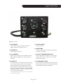
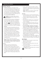
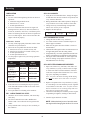
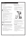
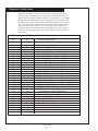
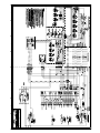
Lugger Control Panel
8
2
1
3
7
6
4
5
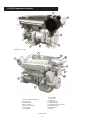
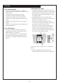
Figure 1b: L6125H
1. TACHOMETER
Shows engine speed in revolutions per minute
(RPM). Numbers are multiples of 100.
5. POTENTIOMETER
Dims panel lights.
2. HOUR METER
Tracks engine running time.
6. ALARM HORN
If alarm sounds, shut down engine if possible and
investigate immediately.
3. DC VOLTMETER
When engine is stopped, shows condition of battery.
When engine is running, shows voltage output of
alternator.
7. COOLANT TEMPERATURE GAUGE
Shows temperature of cooling water. If the gauge
registers above 200o F, or below 140o F, stop the
engine and investigate.
4. KEY SWITCH
Turn key clockwise to first position to switch current
on. Continue turning clockwise to start the engine.
When the engine starts, immediately turn the key
back to the first position while the engine is running.
The key must be kept in the first or on position while
the engine is running. Turn the key counterclockwise
until it stops to stop the engine.
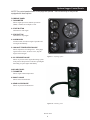
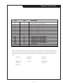
Note: Optional flybridge panels have engine start switches instead
8. OIL PRESSURE GAUGE
Shows oil pressure in the engine lubricating system.
If the pressure drops below 15 PSI at a speed higher
than idling, stop the engine immediately.
of keys switches (see page 8).
OL6125 06/10