1
GE Infrastructure
Sensing
Druck PV 103R
Pump unit
Service manual K232
Druck PV 103R Service Manual
INTRODUCTION
Purpose
This technical manual provides servicing instructions and a parts list to an intermediate level of
maintenance for the Druck PV 103 pump units.
Scope
This technical manual contains a constructional description, a functional description explaining the
theory of operation, servicing, replacing parts and testing procedures. An illustration parts list details
the parts that can be replaced. The test equipment and special tools required for the recommended
maintenance level are listed. A supplementary servicing chapter describes procedures to update
older units to the latest build standard.
Associated Druck Documents:
K141
K232 Issue No. 2
-
PV 103R User Manual
Page i
Druck PV 103R Service Manual
TABLE OF CONTENTS
Preliminary pages
Table of contents (this table)
Introduction
Purpose
Scope
Glossary
Abbreviations
Chapter
1
DESCRIPTION
2
SCHEDULED SERVICING
3
SUPPLEMENTARY SERVICING
4
REPLACING PARTS
5
TESTING
6
ILLUSTRATED PARTS LIST
K232 Issue No. 2
Page ii
Druck PV 103R Service Manual
GLOSSARY
Terminology
The terminology used in this manual is specific and individual interpretation must not be introduced.
The terms are defined as follows:
Adjust:
To bring to a more satisfactory state; to manipulate controls, levers, linkages, etc. to return equipment
from an out-of-tolerance condition to an in-tolerance condition.
Align:
To bring into line; to line up; to bring into precise adjustment, correct relative position or coincidence.
Assemble:
To fit and secure together the several parts of; to make or form by combining parts.
Calibrate:
To determine accuracy, deviation or variation by special measurement or by comparison with a
standard.
Check:
Make a comparison of a measure of time, pressure, temperature, resistance, dimension or other
quality with a known figure for that measurement.
Disconnect:
To detach the connection between; to separate keyed or matched equipment parts.
Dismantle:
To take apart to the level of the next smaller unit or down to all removable parts.
Ensure:
To confirm that a proper condition exists; to find out with certainty.
Examine:
To perform a critical visual observation or check for specific conditions; to test the condition of.
Fit:
Correctly attach one item to another.
Inspect:
Review the work carried out by Specialists to ensure it has been performed satisfactorily.
Install:
To perform operations necessary to properly fit an equipment unit into the next larger assembly or
system.
Maintain:
To hold or keep in any particular state or condition especially in a state of efficiency or validity.
Operate:
Ensure that an item or system functions correctly as far as possible without the use of test equipment
or reference to measurement.
Readjust:
To adjust again; to move back to a specified condition; to bring back to an in-tolerance condition.
Reconnect:
To rejoin or refasten that which has been separated.
Refit:
Fit an item which has previously been removed.
K232 Issue No. 2
Page iii
Druck PV 103R Service Manual
Terminology (continued)
Remove:
To perform operations necessary to take an equipment unit out of the next larger assembly or
system. To take off or eliminate. To take or move away.
Repair:
To restore damaged, worn out or malfunctioning equipment to a serviceable, usable or operable
condition.
Replace:
Remove an item and fit a new or a serviced item.
Reset:
To put back into a desired position, adjustment or condition.
Service:
To perform such operations as cleaning, lubricating and replenishing to prepare for use.
Test:
Ascertain by using the appropriate test equipment that a component or system functions correctly.
K232 Issue No. 2
Page iv
Druck PV 103R Service Manual
Abbreviations
The following abbreviations are used in this manual; the abbreviations are the same in the singular
and plural.
A
abs
a.c.
ALT
CAS
d.c.
e.g.
EOC
EPR
EPROM
etc.
Fig.
ft
g
Hg
Hz
IAS
i.e.
IEEE 488
in
kg
LED
(M)
m
mA
max
mbar
min
mm
mV
No.
N.m.
Para.
Ps
psi
Pt
Qc
QFE
QNH
ROC
SCPI
TAS
TE
V
Vc
Vt
+ve
-ve
°C
K232 Issue No. 2
Ampere
Absolute
Alternating current
Altitude
Calibrated airspeed
Direct current
For example
End of conversion
Engine pressure ratio
Electrically programmable read only memory
And so on
Figure
Foot
Gauge
Mercury
Hertz
Indicated airspeed
That is
Institute of Electrical and Electronic Engineers standard 488 data
Inch
Kilogram
Light emitting diode
Magnesium alloy
Metre
Milliampere
Maximum
Millibar
Minute or minimum
Millimetre
Millivolts
Number
Newton metre
Paragraph
Static pressure
Pounds per square inch
Total pressure
Differential pressure Ps/Pt
Local atmospheric pressure
Barometric pressure at sea level
Rate of climb
Standard commands for programmable instruments
True airspeed
Test equipment
Volts
Calibrated velocity
True velocity
Positive
Negative
Degrees Celsius
Page v
Druck PV 103R Service Manual
K232 Issue No. 2
Page vi
Druck PV 103R Service Manual
Chapter 1
Description
CONTENTS
Introduction ...............................................................
Build standard 1 ........................................................
Brief Description .......................................................
Specification Build standard 1 ..................................
Build standard 2 ........................................................
Specification, Build standard 2 .................................
Build standard 3 ........................................................
Specification, Build standard 3 .................................
Build standard 4 ........................................................
Specification, Build standard 4 .................................
Para.
2
2
2
5
6
8
9
10
11
12
Illustrations
fig.
Build
Build
Build
Build
Build
Build
Build
K232 Issue No. 2
standard 1, General view ................................
standard 1, Schematic diagram ......................
standard 1, Internal view, ................................
standard 2, Rear panel ....................................
standard 2, Schematic diagram ......................
standard 3, Schematic diagram ......................
standard 4, Schematic diagram ......................
Page 1-1
1-1
1-2
1-3
1-4
1-5
1-6
1-7
Druck PV 103R Service Manual
INTRODUCTION
1.
Since the introduction of the PV 103 in March 1994 there have been four build standards.
With all four build standards there are two variants, the rack and flightline. Each standard has
improved either the performance and reliability or extended the servicing period.
2.
The PV 103R rack-mounted variant provides pressure and vacuum supplies for use with
other rack-mounted equipment (such as the ADTS 405) as part of an instrument and air data
component servicing and testing facility. Alternatively the unit can be fitted in a trolley as part of
a mobile air data test system.
Note:
The suffix R was added in 1998 to show the difference between the two
variants.
3.
The PV 103 flightline variant is part of the ADTS 405F air data test system providing
complete pressure and vacuum measuring and control for on-aircraft sense and leak testing and
functional tests of air data instruments, components and systems. The ADTS 405F comprises an
electronics rack (ADTS 405) and pump rack (PV 103) enclosed in a high density, polyethylene
case. The operating details and service information for these flightline units are contained on
Druck publications K114 ADTS 405 User Manual and K228 ADTS 405 Service Manual.
Build Standard 1
4.
The first standard uses a compact custom pump assembly based on a brushless d.c.
motor, custom crankcase and eccentric driving four rocking PTFE sealed piston, cylinder and flap
valve assemblies. The pressure/vacuum output connect to Vacuum (1) and Vacuum (2) and to
Pressure all located on the rear panel.
Brief Description
5.
The pump consists of an electric motor driving a pump and controlled by a controller PCB.
The rack is cooled by an electric fan. A power supply unit produces electrical power for the
motor circuit, fan and circuits to the electronics rack. The power supply switch, elapsed time
indicator and fuses are located on the front panel of the rack.
6.
The pump is driven by a brushless DC motor, Hall effect sensors provide feedback to the
motor drive circuits. The power supply unit receives power through a switch and fuse to produce
24 V DC for the motor drive circuits and the power indicator.
7.
The pump consists of four reciprocating pistons on a central eccentric. One piston head is
configured for pressure and the other three for vacuum. Reed valves in the piston heads control
the direction of air flow. One of the vacuum heads provides an initial (rough) vacuum that in turn
feeds the other two vacuum heads.
8.
Air from the pressure head passes through a copper cooling coil located behind the front
panel air intake grill. Any moisture in the cooled air condenses, a coalescing filter bowl traps the
condensed moisture. A constant air bleed forces the discharge of condensed moisture (water)
through a needle restrictor to the water drain pipe.
K232 Issue No. 2
Page 1-2
Druck PV 103R Service Manual
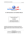
Figure 1-1 Build standard 1, General view
Figure 1-2 Build standard 1, Schematic Diagram
K232 Issue No. 2
Page 1-3
Druck PV 103R Service Manual
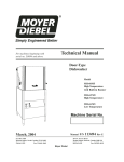
5
2
3
6
4
7
1
9
10
11
1
2
3
4
5
6
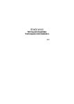
Water drain filter
Pneumatic output connections
Pump and Motor assembly
Fan assembly
Motor controller PCB
Power supply filter connector
7
8
9
10
11
Power supply unit
Elapsed time indicator
Fuse holder
Switch
Filter
Figure 1-3 Build standard 1, Internal view
K232 Issue No. 2
Page 1-4
8
Druck PV 103R Service Manual
Specification Build standard 1
9.
Input
Power supply
............................................................ 90 - 230 Vac 50 - 60 Hz (nominal)
........................................................................110 Vac, 400 Hz (nominal)
......................................................................... continuous rating 300 VA
Output
Pressure (min) ........................................................ 3.5 bar abs (100 inHg abs)
Airspeed rate ......................................................... 1 Mach/min up to 550 knots
...................................................... (into a volume of 10 litres {600 cu in})
.................................................................. 900 knots/min up to 850 knots
........................................................ (into a volume of 2 litres {120 cu in})
Vacuum (max) ...................................... 20 mbar abs/0.49 inHg abs (85,000 ft)
Altitude rate ............................................ 6,000 ft/min rate of climb to 55,000 ft
.................................................... (into a volume of 17 litres {1000 cu in})
..................................................... 15,000 ft/min rate of climb to 85,000 ft
........................................................ (into a volume of 4 litres {240 cu in})
Note:
The vacuum performance is the combined output of Vacuum (1) and Vacuum (2).
On later build standards, Vacuum (1) and Vacuum (2) are internally linked.
Dimensions
width .......................................................................................... 483 mm {19 in}
height ........................................................................................... 178 mm {7 in}
depth ....................................................................................... 266 mm {10.5 in}
weight ........................................................................................... 9.5kg {21 lbs}
Environment
Temperature .................................................... -10°C to +50°C (14°F to 122°F)
(continuous operation)
Position of the unit
The unit must only be operated with the front panel in the vertical position.
Note:
The unit must not be operated in any other position because an internal water drain
will be inverted.
Calibration and adjustments ........................................................... not required
K232 Issue No. 2
Page 1-5
Druck PV 103R Service Manual
Build Standard 2
10. The second standard included improvements in materials and assembly methods that had
been well proven during design/development of the military versions. A improved power supply
included an upgraded motor control PCB. When this unit is used with an ADTS 405 the speed of
the motor is controlled by the mode selection of the ADTS 405. During measurement mode the
motor speed slows to reduce noise output and wear. An additional 15-way D-type connector was
fitted to the rear panel to connect to the ADTS 405 mode selection.
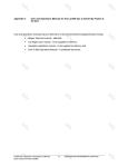
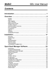
11. Build standard 2 introduced a profiled spacer on the piston crown enabling the piston seals to
be reversed for more effective vacuum generation. A new style of cylinder, with hard anodising and
high polish, improved seal wear and reduced leakage. To keep stroke lengths correct a similar
profile spacer is used on the pressure piston. Improvements to piston alignment with the piston seal
changes has increased the servicing interval to 3000 hours. The output pressures can be sustained
at 3.5 bar and 20 mbar absolute.
5
5
4
4
3
3
2
1
1
(a)
(b)
Piston head for pumps
of build standard 1
1
2
3
(c)
Piston head for pumps of build standard 2
Connecting rod
Spacer
Piston seal
4
5
Retainer
Central countersunk screw
12. Noise reduction has been achieved by increasing the filter area of the pressure air intake; air
is drawn from inside the crankcase through an end-mounted porous plate. A robust three-axis antivibration mounting reduces the effects of external vibration. Originally designed and developed for
the ADTS 405F, this mounting fits into a surface mounting adaptor cradle.
K232 Issue No. 2
Page 1-6
Druck PV 103R Service Manual
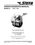
power
connector
(IEC type)
cooling output
grill
pneumatic output connectors
expansion connector
Figure 1-4 Build standard 2, Rear Panel
Figure 1-5 Build standard 2, Schematic Diagram
K232 Issue No. 2
Page 1-7
Druck PV 103R Service Manual
Specification Build standard 2
13.
Input
Power supply
............................................................ 90 - 230 Vac 50 - 60 Hz (nominal)
........................................................................110 Vac, 400 Hz (nominal)
......................................................................... continuous rating 300 VA
Output
Pressure (min) ........................................................ 3.5 bar abs (100 inHg abs)
Airspeed rate ......................................................... 1 Mach/min up to 550 knots
...................................................... (into a volume of 10 litres {600 cu in})
.................................................................. 900 knots/min up to 850 knots
........................................................ (into a volume of 2 litres {120 cu in})
Vacuum (max) ...................................... 20 mbar abs/0.49 inHg abs (85,000 ft)
Altitude rate ............................................ 6,000 ft/min rate of climb to 55,000 ft
.................................................... (into a volume of 17 litres {1000 cu in})
..................................................... 15,000 ft/min rate of climb to 85,000 ft
........................................................ (into a volume of 4 litres {240 cu in})
Note:
The vacuum performance is the combined output of Vacuum (1) and Vacuum (2),
these are internally linked.
Dimensions
width .......................................................................................... 483 mm {19 in}
height ........................................................................................... 178 mm {7 in}
depth ....................................................................................... 266 mm {10.5 in}
weight ........................................................................................... 9.5kg {21 lbs}
Environment
Temperature .................................................... -10°C to +50°C (14°F to 122°F)
(continuous operation)
Position of the unit
The unit must only be operated with the front panel in the vertical position.
Note:
The unit must not be operated in any other position because an internal water drain
will be inverted.
Calibration and adjustments ................................................. not required
K232 Issue No. 2
Page 1-8
Druck PV 103R Service Manual
Build Standard 3
14. This standard includes a completely revised chassis design, new cooler and water drain
assembly and a water release valve. In this standard two improvements were made that increased
efficiency:
!
The replacement of the copper cooling coil with a compact cooler block. Heat is dissipated
through the block and then to the chassis. The block contains a stainless steel knitmesh proving a
large cooling area for the flow of air.
!
The existing water trap/discharge system required a constant bleed of air, this affected the
efficiency of the pump. To improve pumping efficiency a release valve, style regulator only purges
the water drain filter when the pump back pressure rises to 3.5 bar gauge. At power-down, an
energised-closed solenoid valve opens discharging air from the pressure head. This also prevents
pump stall on restart with too much back pressure.
Figure 1-6 Build standard 3, Schematic Diagram
K232 Issue No. 2
Page 1-9
Druck PV 103R Service Manual
Specification Build standard 3
15.
Input
Power supply
............................................................ 90 - 230 Vac 50 - 60 Hz (nominal)
........................................................................ 110 Vac, 400 Hz (nominal)
......................................................................... continuous rating 300 VA
Output
Pressure (min) ......................................................... 3.5 bar abs (100 inHg abs)
Airspeed rate ......................................................... 1 Mach/min up to 550 knots
...................................................... (into a volume of 10 litres {600 cu in})
.................................................................. 900 knots/min up to 850 knots
........................................................ (into a volume of 2 litres {120 cu in})
Vacuum (max) ...................................... 20 mbar abs/0.49 inHg abs (85,000 ft)
Altitude rate ............................................ 6,000 ft/min rate of climb to 55,000 ft
.................................................... (into a volume of 17 litres {1000 cu in})
..................................................... 15,000 ft/min rate of climb to 85,000 ft
........................................................ (into a volume of 4 litres {240 cu in})
Note:
The vacuum performance is the combined output of Vacuum (1) and Vacuum (2),
these are internally linked.
Dimensions
width .......................................................................................... 483 mm {19 in}
height ........................................................................................... 178 mm {7 in}
depth ....................................................................................... 266 mm {10.5 in}
weight ........................................................................................... 9.5kg {21 lbs}
Environment
Temperature .................................................... -10°C to +50°C (14°F to 122°F)
(continuous operation)
Position of the unit
The unit must only be operated with the front panel in the vertical position.
Note:
The unit must not be operated in any other position because an internal water drain
will be inverted.
Calibration and adjustments ........................................................... not required
K232 Issue No. 2
Page 1-10
Druck PV 103R Service Manual
Build Standard 4
16. This build standard replaces obsolete parts and improves on the revised chassis design, new
cooler and water drain assembly and a water release valve of build standard 3. In this standard,
improvements were made that increased efficiency:
!
The main improvement combines the cooler and water drain into one assembly with a
compact cooler block. Heat is dissipated through the block and then to the chassis. A reduced
number of pipe interconnections reduces the potential leak paths. Both changes improve pumping
efficiency.
!
A pressure release valve, in the regulator, only purges the water drain filter when the pump's
back pressure rises to 3.5 bar gauge. At power-down, an energised-closed solenoid valve opens
discharging air from the pressure head.
Figure 1-7 Build standard 4, General view
K232 Issue No. 2
Page 1-11
Druck PV 103R Service Manual
Figure 1-8 Build standard 4, Schematic Diagram
K232 Issue No. 2
Page 1-12
Druck PV 103R Service Manual
2
3
4
5
1
6
10
9
8
7
1
2
3
4
5
Water trap/cooler assembly
Pneumatic output connections
Pump and Motor assembly
Fan assembly
Power supply filter connector
6
7
8
9
10
Power supply unit
Switch
Fuse holder
Elapsed time indicator
Filter
Figure 1-9 Build standard 4, Internal view
K232 Issue No. 2
Page 1-13
Druck PV 103R Service Manual
Specification Build standard 4
17.
Input
Power supply
.......................................................... 88 - 260 Vac 47 - 440 Hz (nominal)
......................................................................... continuous rating 300 VA
Output
Pressure (max) ............................................... 3.5 bar gauge (100 inHg gauge)
Airspeed rate ......................................................... 1 Mach/min up to 550 knots
...................................................... (into a volume of 10 litres {600 cu in})
.................................................................. 900 knots/min up to 850 knots
........................................................ (into a volume of 2 litres {120 cu in})
Vacuum (max) ...................................... 20 mbar abs/0.49 inHg abs (85,000 ft)
Altitude rate ............................................ 6,000 ft/min rate of climb to 55,000 ft
.................................................... (into a volume of 17 litres {1000 cu in})
..................................................... 15,000 ft/min rate of climb to 85,000 ft
........................................................ (into a volume of 4 litres {240 cu in})
Note:
The vacuum performance is the combined output of Vacuum (1) and Vacuum (2).
Dimensions
width .......................................................................................... 483 mm {19 in}
height ........................................................................................... 178 mm {7 in}
depth ....................................................................................... 266 mm {10.5 in}
weight ........................................................................................... 9.5kg {21 lbs}
Environment
Temperature .................................................... -10°C to +50°C (14°F to 122°F)
(continuous operation)
Position of the unit
The unit must only be operated with the front panel in the vertical position.
Note:
The unit must not be operated in any other position because an internal water drain
will be inverted.
Calibration and adjustments ........................................................... not required
K232 Issue No. 2
Page 1-14
Druck PV 103/R Service Manual
Chapter 2
Scheduled Servicing
CONTENTS
title
para.
Servicing ................................................................... 1
Maintenance ............................................................. 2
Scheduled Procedures .................................... 2.1
1000 Hours ...................................................... 2.2
3000 Hours ...................................................... 2.3
ILLUSTRATIONS
title
fig.
Bulkhead fittings ....................................................... 2-1
Water drain filter build standard 1 and 2 .................. 2-2
Water/cooler trap assembly build standard 3 .......... 2-3
Water/cooler trap assembly build standard 4 .......... 2-4
Cylinder head ........................................................... 2-5
Piston head ............................................................... 2-6
K232 Issue No. 2
Page 2-1
Druck PV 103/R Service Manual
1
SERVICING
WARNING:
VOLTAGES IN EXCESS OF 30 VOLTS (RMS) AC OR 50 VOLTS DC, IN
CERTAIN CIRCUMSTANCES CAN BE LETHAL. CARE MUST BE TAKEN
WHEN WORKING ON LIVE, EXPOSED CONDUCTORS.
General
1.
Absolute cleanliness of the work area, tools and equipment must be observed. Expendable
items must be discarded.
2.
Disconnect and remove all the electrical and pneumatic connections.
Cover
3.
Unscrew and remove the ten screws and shakeproof washers securing the cover to the
chassis. Slide cover off to the rear.
2
MAINTENANCE
General
1.
To maintain the unit in a safe and serviceable condition carry out the following scheduled
maintenance procedures.
2.1 SCHEDULED PROCEDURES
The scheduled maintenance procedures are carried out at 1000 and 3000 hours recorded on the
elapsed time indicator on the front panel of the unit. The recommended period of servicing is based
on a temperate environment. If the unit is used in an environment with higher humidity or higher
levels of dust the periodicity must be increased accordingly. Consult DRUCK if there is any doubt.
2.2 1000 Hours
WARNING:
DISCONNECT THE POWER SUPPLY BEFORE PROCEEDING WITH
MAINTENANCE.
Every 1000 hours, replace the following components:
! Bulkhead fittings
! Water drain filter - internal
! Pneumatic filters - (mufflers) internal
Bulkhead Fittings BS1, BS2 and BS3 (Fig. 2-1)
The pneumatic output connectors consist of bulkhead fitting with an integral wire knitmesh
filter and, located in a small groove, an o-ring seal. The bulkhead fittings are secured by two
screws to the front or rear panels. The pneumatic output pipe connects to the bulkhead fitting
by a union nut and a union screwed into the bore of the bulkhead fitting.
The small o-ring located in the groove of each bulkhead fitting requires regular inspection for
damage and, if necessary, replacement.
Note:
K232 Issue No. 2
BS4 bulkhead fittings have an integral o-ring seal, should this become damaged
the bulkhead fitting must be replaced.
Page 2-2
Druck PV 103/R Service Manual
o-ring seal
bulkhead fitting
Fig. 2-1 Bulkhead fitting
Procedure
Build standard 1, 2 and 3
(1) Unscrew the union nut, disconnect the pneumatic output pipe and collect the bonded seal.
(2)
Unscrew the two screws securing the bulkhead fitting, remove the bulkhead fitting.
(3)
Inspect and clean the bulkhead fitting wire knitmesh filter and, if necessary, replace the
bulkhead fitting. Refit the bulkhead fitting and secure with the two screws.
(4)
Fit a new bonded seal and refit the union to the bulkhead fitting.
(5)
Locate the pneumatic output pipe on the union and secure with the union nut.
Water Drain Filter (Fig. 2-2)
Build standard 1 and 2
This unit contains a constant-bleed water drain producing a small flow of exhaust air. The exhaust
air must be checked when the pumps are running. Replace the water drain filter as follows:
(1)
Disconnect the drain pipe to the water drain filter.
(2)
Cut the tyrap securing the water drain filter. Unscrew the clear nylon bowl from the
water drain filter body.
(3)
Remove the clear plastic drain pipe from the clear nylon bowl and replace the drain
inserted in the bowl. Refit the clear plastic drain pipe to the nylon bowl.
(4)
Replace the filter element and refit the clear nylon bowl to the water drain filter body.
Secure the assembled water drain filter with a tyrap.
(5)
Carry out a standard serviceability test detailed in Chapter 5.
K232 Issue No. 2
Page 2-3
Druck PV 103/R Service Manual
filter element
water ejector
tyrap
clear nylon
drain pipe
Fig. 2-2 Water drain filter, build standard 1 and 2
cooler block
filter element
clear nylon
bowl
output
washer
screw
Fig. 2-3 Water/cooler trap assembly, build standard 3
K232 Issue No. 2
Page 2-4
Druck PV 103/R Service Manual
Water/cooler trap assembly (Fig.2-4, BS 3)
Procedure
(1) Unscrew and remove the two screws and washers securing the bracket to the cooler
block.
(2)
Disconnect the drain pipe from the clear nylon bowl, unscrew and remove the clear nylon
bowl and collect the filter.
(3)
Fit a new filter, screw the clear nylon bowl into the filter body. Connect the drain pipe to
the clear nylon bowl.
(4)
Secure the bracket with the two screws and washers.
(5)
Carry out a standard serviceability test detailed in Chapter 5.
spring
washer
hexagonal sockethead screw
assembled pressure
regulator and water
drain body
o-ring
filter element
cooler body
Fig. 2-4 Water/cooler trap assembly, build standard 4
Water/cooler trap assembly (BS 4)
(1) Unscrew and remove the four hexagonal, socket-head screws and four spring washers.
Carefully separate the assembled pressure regulator and water drain body from the
cooler body attached to the front panel.
(2)
Replace the filter element, make sure the o-ring fits correctly and refit the assembled
pressure regulator and water drain body to the cooler body. Secure the assembled
water drain with the four hexagonal, socket-head screws and four spring washers.
K232 Issue No. 2
Page 2-5
Druck PV 103/R Service Manual
Pneumatic Filters
BS1
(1) Two of the four pump heads are filtered by
muffler
high density polythene porous plastic
silencers (mufflers). The pressure pump head
has two intake mufflers, used as filters, and
the initial vacuum head has one discharge
muffler used as a silencer.
(2)
Unscrew the existing mufflers and screw the
new mufflers hand-tight.
Note:
Over-tightening could damage the
muffler threads.
muffler
BS2, BS3 and BS4
(1) An end-mounted porous plate fitted to the crankcase provides the pressure air intake
filter, the pressure pump draws air from inside the crankcase. The initial vacuum head
has one discharge muffler used as a silencer.
(2)
Unscrew the existing muffler and
screw the new muffler hand-tight.
Note:
(3)
porous plate
Over-tightening could
damage the muffler
threads.
Unscrew the four screws and
washers securing the porous
plate to the crankcase. Fit a new
porous plate and secure with the
four screws and washers.
muffler
BS3 and BS4
(1) Two in-line filters connect in the
vacuum output pipes.
(2)
Disconnect the pipe from each end of the in-line filter by releasing the clip. Connect a
new filter and secure with the clips for each filter.
Completion
(1) Refit the cover and reconnect the external pipes and connectors.
K232 Issue No. 2
Page 2-6
Druck PV 103/R Service Manual
2.2 3000 Hours
WARNING:DISCONNECT THE POWER SUPPLY BEFORE PROCEEDING WITH MAINTENANCE.
Every 3000 hours, replace the following components:
!
Piston seals.
!
Cylinder head o-ring seals.
Preparation
1.
Absolute cleanliness of the work area, tools and equipment must be observed. Expendable
items must be discarded.
2.
Disconnect and remove all the electrical and pneumatic connections.
Cover
3.
Unscrew and remove the ten screws and shakeproof washers securing the cover to the
chassis. Slide cover off to the rear.
Cylinder head (Fig. 2-6)
4.
The four pump piston heads are identical in construction but with the pressure piston seal
facing outwards. The o-ring seal locate in grooves in the cylinder head, hexagonal sockethead bolts secure the cylinder head to the pump body. Interposed between the cylinder head
and pump body are valve plates and a spacer. Grooves in the plates locate on the spacer
allowing the correct air flow.
Procedure (Fig. 2-6)
5.
Note:
(1)
Unscrew and remove the four hexagonal socket-head bolts (9) securing the cylinder
head (7). Collect a plain washer (8) from each hexagonal socket-head bolt (9).
Note:
(2)
Inspect the cylinder block for distortion and cracks. Inspect the bore of the cylinder
block scoring or damage. Replace any cylinder that fails inspection.
Rotate by hand the pump to access the piston head. Unscrew and remove the central
countersunk screw (Fig. 2-7, item 5), remove the piston seal (Fig. 2-7, item 3) and
retainer (Fig. 2-7, item 4).
Note:
(4)
Some cylinder heads may have one or more shims fitted, these are matched items.
Remove the cylinder head complete with valve plates (3 and 5) and spacer (4). Record
the number and position of any shims for use in assembly.
Note:
(3)
The procedure is the same for each of the four pump cylinder heads.
Piston seals must be preformed in accordance with instructions in the seal kit [see
Fig. 2-10].
Replace the preformed piston seal (Fig.2-7, item 3) on the retainer.
Note:
K232 Issue No. 2
The piston seal faces outwards on the pressure piston head and inwards on the
vacuum piston heads. On earlier units with cylinders of the style shown in (Fig. 26, item 1a) all seals point outwards [see Fig. 2-7 (a)].
Page 2-7
Druck PV 103/R Service Manual
1a
1
2
3
4
5
10
6
7
9
8
1
1a
3
5
7
9
Cylinder
Cylinder (earlier pumps)
Valve plate
Valve plate
Cylinder head
Hexagonal socket-head bolt
2
4
6
8
10
O-ring seal
Spacer
O-ring seal
Plain washer
O-ring seal
Fig. 2-6 Cylinder head
(5)
Apply Loctite grade 222 to the threads of the central countersunk screw (Fig. 2-5, Item
5). Locate the assembled piston seal (Fig. 2-7, Item 3) and retainer (Fig. 2-7, Item 4) on
the connecting rod (Fig. 2-7, Item 1) and secure with the central countersunk screw (Fig.
2-7, Item 5).
Note:
(6)
The head of the central countersunk screw must not protrude above the rim of the
retainer.
Fit a new o-ring seal (2) to the inner bore of the cylinder (1). The next step is to fit the
cylinder over the piston head, the piston seal can be damaged if the fitting is not carried
out with great care. The recommended method is as follows:
i
Move the piston head to top dead centre and then to one side, position the
cylinder (1) at an angle to the piston head.
K232 Issue No. 2
Page 2-8
Druck PV 103/R Service Manual
ii
Carefully move the cylinder over the piston head making sure the piston seal
is not distorted. Carefully push the cylinder over the piston head until it is fully
inserted making sure the piston seal is not distorted and is formed in the correct
way (see above).
iii
Align the holes of the cylinder with the threaded holes of the pump body.
5
5
4
4
3
3
2
1
1
(a)
Piston head for earlier pumps
1
2
3
(b)
(c)
Piston head for later pumps
Connecting rod
Spacer
Piston seal
4
5
Retainer
Central countersunk screw
Fig. 2-7 Piston head
(7)
Before assembly, check the valve plates (3 and 5) and spacer (4) remove any dirt by
polishing. Assemble a valve plate (3 and 5) on each side of the spacer (4), locating each
plate on the keys on the spacer. Refit any shims in the recorded position. Fit a new oring seal (6) to the mating face of the cylinder head (7). Fit a new small o-ring seal (10)
to the recess of the cylinder head (7).
(8)
Locate the cylinder head (7) complete with valve plates and spacer over the cylinder (1)
and loosely retain with the four hexagonal socket-head bolts (9) and washers (8).
(9)
Carefully rotate by hand the pump and, if necessary, reposition the assembled cylinder
head for the smoothest rotation. Tighten the four hexagonal socket-head bolts (9) in turn
and diagonally.
(10) Repeat the procedure steps (1) to (9) for all four cylinder heads.
(11) Slowly rotate the pump by hand to make sure the pump rotates smoothly.
(12)
If necessary, readjust a cylinder head to produce a smooth rotation or reduce the noise,
as detailed in step (9).
Completion
6.
(1) Refit the cover and reconnect the external pipes and connectors.
(2)
Test the pump as detailed the Standard Serviceability Test in Chapter 5.
K232 Issue No. 2
Page 2-9
Druck PV 103/R Service Manual
K232 Issue No. 2
Page 2-10
Druck PV 103/R Service Manual
Chapter 3
Supplementary Servicing
CONTENTS
title
para.
General ..................................................................... 3-1
Servicing Supplement ..................................... 3-2
Build Standard Conversions ........................... 3-3
ILLUSTRATIONS
title
fig.
Motor controller cable loom ...................................... 3-1
PSU and motor controller cable loom ...................... 3-2
Piston seal replacement techniques ........................ 3-3
Front panel drilling dimensions ................................ 3-4
Water/cooler trap assembly new wires .................... 3-5
BS3 Water/cooler trap assembly ............................. 3-6
K232 Issue No. 2
Page 3-1
Druck PV 103/R Service Manual
3.1 General
This section contains procedures to replace an obsolete component or to upgrade the unit to a
higher build standard.
Use suitably qualified personnel and good engineering practice for all the procedures. Absolute
cleanliness must be maintained in the work area.
K232 Issue No. 2
Page 3-2
Druck PV 103/R Service Manual
3.2 Servicing supplement
The following is additional information that is intended to assist in the servicing procedures.
Build standard 1
Power supply unit and motor controller PCB
These two components were upgraded and the originals are now obsolete. It is possible to use an
original PSU with an upgraded motor controller PCB. and vice versa; it requires a change of the
electrical loom to achieve this type of replacement. The following instructions detail the necessary
replacement procedures.
Motor controller PCB
To replace the original type with the upgraded PCB proceed as follows:
1.
Disconnect the 8-way and 3-way connectors from the pump/motor assembly.
2.
Disconnect and discard the cable loom with the 7-way Molex socket, at one end (PSU), and to
the 2-way terminal block and the terminal block at the top of the motor controller PCB at the
other.
3.
Remove and discard the motor controller PCB.
Fitting the new motor controller PCB
1.
If necessary, from the top fixing hole for the old motor controller PCB measure 60 mm
vertically down the rear panel and mark for drilling. Using a 3.5 mm drill bit, drill a hole in the
marked position.
2.
Fit the new motor controller PCB and secure using the two M3 x 6 mm pozidrive, panhead
screws and shakeproof washers.
3.
Refer to the new component list on page 3-6 and to figure 3-1 to produce a new cable loom.
4.
Connect the new cable loom to the Molex socket on the PSU.
5.
Connect the 1/4 Faston, red wire, connector to the +24 V on the motor controller PCB.
Connect the 1/4 Faston, black wire, connector to the 0 V on the motor controller PCB.
Connect the two push-on terminals to the 2-way terminal block, observe the colour coding.
6.
Carry out a standard serviceability test detailed in Chapter 5.
Power supply unit
To replace the original type with the upgraded PSU proceed as follows:
1.
Disconnect the 5-way and 8-way connectors from the pump/motor assembly.
2.
Disconnect the 3-way and 7-way Molex power supply sockets from the PSU.
3.
Remove and discard the PSU.
4.
Using a new 4-way Molex connector (Fig.3-2), remove the red wire (terminal 3) from the 7-way
connector and insert it into terminal 3. Repeat this procedure for the black wire (terminal 4)
inserting it into terminal 4 of the new 4-way Molex connector.
5.
Connect the two red wires from the 7-way connector terminals 1 and 2 to the red flying cable
from the new PSU. Connect the three black wires from the 7-way connector terminals 5, 6
and 7 to the black flying cable from the new PSU.
6.
Temporarily position the new PSU in the pump unit case. Connect the 5-way connector to
CON1 and the 4-way connector to CON 2 on the new PSU.
CAUTION:
7.
The M3 screws securing the PSU must not be longer than 6 mm. Longer
screws damage the internal PCB and components.
Locate and secure the new PSU to the pump unit case with the correct screws and washers.
8.
Connect the 8-way connector and the 3-way connector on the new PSU.
K232 Issue No. 2
Page 3-3
Druck PV 103/R Service Manual
Fitting the new type PSU and motor controller PCB (continued)
9.
Carry out a standard serviceability test detailed in Chapter 5.
Fig. 3-1 Motor controller cable loom
Fig. 3-2 New PSU and motor controller cable loom
K232 Issue No. 2
Page 3-4
Fig. 3-3 Piston seal replacement techniques
Druck PV 103/R Service Manual
K232 Issue No. 2
Page 3-5
Druck PV 103/R Service Manual
3.3
Build standard conversions
This section provides instructions to convert the water drain trap assembly of old build standards to
the water/cooler assembly of the latest build standard.
BS 1 to BS 4 (Fig 2-2 and 2-4)
New component list
Item/
Ref.
Description
3-10a†
.Cooling assembly, water trap
[post MOD 04]
..Body, cooler
..Valve, pressure release
.Screw, M4x 30
.Pipe assembly
.Cable looms, assembly
[set of 5 looms]
-
†
†
†
†
†
Manufacturer's Part Number
QTY
ref
AS405-17-1728M1
AS405-18-1728M1
AS405-24-1728M1
see fig.3-5 to manufacture cable
1
1
4
1
1
QTY
Redundant component list
Item/
Ref.
Description
Manufacturer's Part Number
1-10
.Housing,mist filter
[OBSOLETE pre MOD 04]
Coil, cooling
[OBSOLETE pre MOD 04]
.Pipe assembly
[OBSOLETE pre MOD 04]
401-022
NP
-
NP
-
NP
-
Procedure
1.
Unscrew and disconnect the output union and the input union of the water drain trap.
2.
Cut the tyrap securing the water drain filter.
3.
Release the water drain trap from the spring clip, remove the drain pipe from the clear nylon
bowl. Discard the water drain trap. Unscrew and remove the two screws securing the spring
clip, discard the screws and spring clip.
4.
Unscrew and remove the clips retaining the cooling coil. Discard the cooling coil and clips.
5.
Disconnect the pressure output pipe from the pump head. Remove and discard the pipes and
cooling coil.
6.
Front panel
Note:
Take appropriate precautions to prevent swarf contamination of the unit from the
following procedure. [Service tip - turn unit upside down when drilling.]
Mark out the front panel using the dimensions detailed in figure 3-4. Drill four M3 holes in the
front panel.
7.
Locate the new water cooler assembly and secure to the front panel with the four screws and
washers.
8.
Connect the wires for the pressure bleed valve solenoid on the water/cooler assembly as
detailed in Figure 3-5.
9.
Connect the new pressure output pipe to the output port of the pump head. Connect the other
end to the input connection of the water/cooler assembly.
K232 Issue No. 2
Page 3-6
Druck PV 103/R Service Manual
Figure 3-4 Front panel drilling dimensions
circuit identification numbers change with build standard
Item Description
1
2
3
part no.
Housing, Molex 165-019
Crimp
164-004
Cable, black
192-073
qty
Item Description
part no.
qty
1
4
a/r
4
5
6
Sleeve
Braid
Cable, red
208-167
208-339
192-078
1
a/r
a/r
Item Manufacturer
part no.
Item Manufacturer
part no.
1
2
Molex
Molex
4
5
6
CGAT-6/2-1.2m
Helagain 3 mm grey
192-078
3
Druck
22-01-2025
08-55-0111
08-56-0115
192-073
or
Raychem
Hellerman
Druck
Figure 3-5 Water/cooler assembly new wires
10.
Connect the new pipe to the output union of the water drain trap and the output connection of
the rear panel. Connect the water drain pipe, make sure the other end locates in the grommet
for correct venting of the water/cooler assembly.
11.
Carry out an inspection of the unit look for loose connections and/or disturbance of the internal
components.
12.
Carry out a Standard Serviceability Test detailed in Chapter 5.
K232 Issue No. 2
Page 3-7
Druck PV 103/R Service Manual
BS 2 to BS 4 (Fig 2-2 and 2-4)
New component list
Item/
Ref.
Description
3-10a†
.Cooling assembly, water trap
[post MOD 04]
..Body, cooler
..Valve, pressure release
.Screw, M4x 30
.Pipe assembly
.Cable looms, assembly
[set of 5 looms]
-
†
†
†
†
†
Manufacturer's Part Number
QTY
ref
AS405-17-1728M1
AS405-18-1728M1
AS405-24-1728M1
see fig.3-5 to manufacture cable
1
1
4
1
1
Redundant component list
Item/
Ref.
Description
Manufacturer's Part Number
2-10
.Filter, water drain
[OBSOLETE pre MOD 04]
.Pipe assembly
[OBSOLETE pre MOD 04]
ADTS405-1728-17-M0
NP
-
NP
-
†
QTY
Procedure
1.
Unscrew and disconnect the right-angled output union from the pressure output of the pump/
motor assembly and collect the bonded seal.
2.
Cut the tyrap securing the water drain filter.
3.
Release the water drain trap from the spring clip, remove the drain pipe from the clear nylon
bowl. Discard the water drain trap. Unscrew and remove the two screws securing the spring
clip, discard the screws and spring clip.
4.
Unscrew and remove the clips retaining the cooling coil. Discard the cooling coil and clips.
5.
Front panel
Note:
Take appropriate precautions to prevent swarf contamination of the unit from the
following procedure. [Service tip - turn unit upside down when drilling.]
Mark out the front panel using the dimensions detailed in figure 3-4. Drill four M3 holes in the
front panel.
6.
Locate the new water cooler assembly and secure to the front panel with the four screws and
washers.
7.
Connect the wires for the pressure bleed valve solenoid on the water/cooler assembly as
detailed in Figure 3-5.
8.
Connect the new pressure output pipe to the output port of the pump head. Connect the other
end to the input connection of the water/cooler assembly.
9.
Connect the new pipe to the output union of the water drain trap and the output connection of
the rear panel. Connect the water drain pipe, make sure the other end locates in the grommet
for correct venting of the water/cooler assembly.
10.
Carry out an inspection of the unit look for loose connections and/or disturbance of the internal
components.
11.
Carry out a Standard Serviceability Test detailed in Chapter 5.
K232 Issue No. 2
Page 3-8
Druck PV 103/R Service Manual
Output union
Drain pipe
Water trap
Pressure
relief
valve
Cooler
block
Bracket
Screw
Input union
Washer
Screw
Figure 3-6 BS 3 Water/cooler trap assembly
BS 3 to BS 4 (Fig 3-5)
New component list
Item/
Ref.
Description
Manufacturer's Part Number
QTY
3-10a†
.Cooling assembly, water trap
post MOD 04
AS405-17-1728M1
1
-
.Cable looms, assembly
[set of 5 looms]
AS405-24-1728M1
see fig.3-5 to manufacture cable
1
†
Redundant component list
Item/
Ref.
Description
Manufacturer's Part Number
QTY
3-10
.Valve, pressure relief
[OBSOLETE pre MOD 04]
.Filter, water drain
[OBSOLETE pre MOD 04]
.Solenoid, pressure bleed valve
[OBSOLETE pre MOD 04]
ADTS405-1728-18-M0
NP
ADTS405-1728-17-M0
NP
401-207
NP
-11
-12
K232 Issue No. 2
Page 3-9
Druck PV 103/R Service Manual
BS 3 to BS 4 (Fig 3-5) [continued]
Procedure
1.
Unscrew and disconnect the right-angled output union from the pressure output of the pump/
motor assembly and collect the bonded seal.
2.
Unscrew and disconnect the right-angled input union from the bottom of the water cooler block
and collect the bonded seal.
3.
Unscrew and disconnect the right-angled output union and collect the bonded seal.
4.
Withdraw the drain pipe from the rear panel grommet.
5.
Unscrew and remove the four screws and washers securing the assembly to the chassis of
the unit. Remove the assembly and discard.
6.
Disconnect the two cables to the pressure bleed valve. Unscrew and remove the two screws
and washers securing the dump valve to the chassis of the pump unit.
7.
Remove and discard the dump valve.
8.
Disconnect, remove and discard the existing pressure bleed valve cable loom.
9.
Locate the new water cooler assembly and secure to the front panel with the four screws and
washers.
10.
Connect the wires for the pressure bleed valve solenoid on the water/cooler assembly as
detailed in Figure 3-6.
11.
Connect the new pressure output pipe to the output port of the pump head. Connect the other
end to the input connection of the water/cooler assembly.
12.
Connect the new pipe to the output union of the water drain trap and the output connection of
the rear panel. Connect the water drain pipe, make sure the other end locates in the grommet
for correct venting of the water/cooler assembly.
13.
Carry out an inspection of the unit look for loose connections and/or disturbance of the internal
components.
14.
Carry out a Standard Serviceability Test detailed in Chapter 5.
K232 Issue No. 2
Page 3-10
Druck PV 103/R Service Manual
Chapter 4
Replacing Parts
CONTENTS
title
4
K232 Issue No. 2
para.
REPLACING PARTS
DISMANTLING ................................................ 4-1
Power Supply Unit ........................................... 4.2
Motor controller PCB ....................................... 4-3
Pump and Motor assembly ............................. 4.4
Filter ................................................................. 4.5
Fan assembly .................................................. 4-6
Elapsed time indicator ..................................... 4.7
Switch .............................................................. 4.8
LED assembly ................................................. 4-9
Pressure release valve ................................... 4-10
Water drain filter (BS 1 and 2) ........................ 4-11
Water/cooler trap assembly (BS 3) ................. 4-12
Water/cooler trap assembly (BS4) .................. 4-13
Dump valve solenoid (BS 3) ........................... 4-14
Cylinder block .................................................. 4-15
Anti-vibration mounting ................................... 4-16
Power supply filter connector .......................... 4-17
ASSEMBLING ................................................. 4-18
Power supply filter connector .......................... 4-19
Anti-vibration mounting ................................... 4-20
Cylinder block .................................................. 4-21
Dump valve solenoid (BS 3) ........................... 4-22
Page 4-1
Druck PV 103/R Service Manual
CONTENTS (continued)
title
para.
Water/cooler trap assembly (BS4) .................. 4-23
Water/cooler trap assembly (BS 2 and 3) ...... 4-24
Water drain filter (BS 1) .................................. 4-25
Pressure release valve ................................... 4-26
LED assembly ................................................. 4-27
Switch .............................................................. 4.28
Elapsed time indicator ..................................... 4.29
Fan assembly .................................................. 4-30
Filter ................................................................. 4.31
Pump and Motor assembly ............................. 4.32
Motor controller PCB ....................................... 4-33
Power Supply Unit ........................................... 4.34
Completion ...................................................... 4.35
ILLUSTRATIONS
title
fig.
Fan assembly BS 3 .................................................. 3-1
LED assembly .......................................................... 3-2
Water drain filter (BS1) ............................................. 3-3
Water/cooler trap assembly (BS2 and 3) ................ 3-4
Cooler/water trap assembly (BS4) .......................... 3-5
K232 Issue No. 2
Page 4-2
Druck PV 103/R Service Manual
4
REPLACING PARTS
4.1
DISMANTLING
General
1.
Disconnect the power supply from the pump unit before dismantling. Unscrew and remove the
screws securing the top panel to gain access to the components.
2.
Chapter 6 contains part numbers and details of all the replacement parts described in this
chapter.
4.2
1.
Power Supply Unit
Release the pump/motor assembly cable from the clamp on top of the PSU. Disconnect the
two connectors on top of the PSU.
2.
Unscrew and remove the four screws securing the PSU to the rear panel.
3.
Carefully remove the PSU from the pump rack and disconnect the cable connectors on the
PSU.
4.3 Motor Controller PCB
BS1
1.
Note the connections to the PCB and then disconnect the cables.
2.
Unscrew and remove the two screws securing the PCB bracket to the rear panel.
BS2, BS3 and 4
1.
To access the PCB, remove the PSU as detailed in paragraph 4.2 above.
2.
Unscrew and remove the screws securing the cover of the PSU and remove the PCB.
4.4
1.
Pump and Motor Assembly
Disconnect the two vacuum and one pressure output pipes with the swivel right-angle fittings
on the cylinder heads of the pump.
Note:
2.
On earlier pump/motor assemblies, output pipes are pipe-compressing nut unions.
Release the cable loom from the cable clamp and disconnect the two electrical connectors
from the PSU.
BS1
3.
Unscrew the four nuts securing pump and motor assembly to the mounting pillars, then
remove the nuts and washers.
4.
Carefully remove the pump and motor assembly from the chassis.
BS2, BS3 and 4
5.
Unscrew the four nuts bolts and washers securing the pump and motor assembly and bracket
to the chassis.
6.
Carefully remove the pump and motor assembly from the bracket.
7.
Unscrew the three nuts, bolts and washers securing the pump and motor assembly in the
bracket and separate the pump and motor assembly and bracket.
K232 Issue No. 2
Page 4-3
Druck PV 103/R Service Manual
1
2
3
4
*
Grill
Screw
Spring washer
Fan
BS 1 only
5
6
7
8
Power supply cable connector
Screw
Spring washer
EMC grill
Figure 4-1 Fan assembly BS1, BS2, BS3 and 4
K232 Issue No. 2
Page 4-4
Druck PV 103/R Service Manual
4.5
1.
Fan filter
Using a screwdriver carefully lever frame of the filter and remove the frame and filter from
the front panel.
4.6
1.
Fan assembly
Remove the fan filter from the front panel of the unit as detailed in paragraph 4.5 above.
2.
Disconnect the two power supply cable connectors (5) from the terminal block.
3.
Unscrew and remove the four screws and washers securing the fan to the rear panel.
Unscrew and remove the four screws and washers securing the fan grill to the inner flange
of the fan.
4.7 Elapsed time indicator
BS1 and 2
1.
Disconnect the two wires, push out the ETI.
BS3 and 4
2.
Disconnect the two connections at the rear of the ETI. Unscrew the two securing screws,
nuts and four washers and remove the ETI.
4.8
1.
Switch
Take note of the wires and terminations connected to the switch. Disconnect the wires to
the switch. Unscrew and remove the retaining nut securing the switch to the front panel,
remove the switch and collect the washer.
2
1
3
4
1
LED
2
Locking collar
3
Insulating sleeve
4
Cables
Figure 4-2 LED assembly
4.9
1.
LED assembly
Remove the insulating sleeve (3) from the rear of the assembly (1).
2.
Note and record the colours of the cable to the positive and negative cables (4) of the LED
assembly. Unsolder the two cables (4).
3.
Push out the locking collar (2) and then the push the LED assembly out of the front panel.
K232 Issue No. 2
Page 4-5
Druck PV 103/R Service Manual
4.10 Pressure relief valve (BS 3)
1.
Disconnect the two pipes to the pressure relief valve. Unscrew the retaining nut and
washer and remove the pressure relief valve.
4.14 Water drain filter (Figure 4-3)
BS 1 and 2
7
6
1
3
5
2
4
1
3
5
7
Filter element
Water ejector
Tyrap
Output union
2
4
6
Clear nylon bowl
Drain pipe
Input union
Figure 4-3 Water drain filter
1.
Unscrew and disconnect the output union (7) and the input union (6).
2.
Cut the tyrap (5) securing the water drain filter.
3.
Remove the unit from the spring clip.
K232 Issue No. 2
Page 4-6
Druck PV 103/R Service Manual
4.15 Water/cooler trap assembly
3
4
2
5
1
6
7
9
8
10
1
3
5
7
9
Cooler block
Output union
Pressure relief valve
Screw
Washer
2
4
6
8
10
Water trap
Drain pipe
Bracket
Input union
Screw
Figure 4-4 Water/cooler trap assembly, build standard 3
(1)
Unscrew and remove the four screws (10) and washers (9) securing the assembly to the
front panel.
(2)
Disconnect the output union (3), input union (8) and drain pipe (4).
(3)
Remove the assembly from unit.
K232 Issue No. 2
Page 4-7
Druck PV 103/R Service Manual
4.13 Cooler/water trap assembly (Figure 4-5)
BS 4
1.
Unscrew and disconnect the right-angled, input pipe (4) and collect the bonded seal.
2.
Unscrew and remove the four screws and washers (5) securing the assembly to the front
panel of the unit.
3.
Disconnect the release valve connections (3).
4.
Disconnect the water drain and the output pipe (7).
5.
Remove the assembly from the unit.
8
7
1
2
6
5
3
4
1
3
5
7
Pressure regulator
Release valve connections
Screw
Output pipe
2
4
6
8
Pressure release valve
Input pipe
Washer
Cooler block
Figure 4-5 Water/cooler trap assembly
K232 Issue No. 2
Page 4-8
Druck PV 103/R Service Manual
4.14 Dump valve solenoid
BS 3
1.
Disconnect the two cables to the dump valve. Unscrew and remove the two screws and
washers securing the valve to the chassis of the pump unit.
2.
Unscrew and disconnect the unions of the input and output pipes.
4.15 Cylinder block
1.
Remove the pump/motor assembly as described in para. 4.4.
2.
Dismantle the pump/motor assembly as described in Chapter 2 para. 2.2.
Note:
3.
Unscrew and remove the four hexagonal socket-head bolts (9) securing the cylinder head
(7). Collect a plain washer (8) from each hexagonal socket-head bolt (9).
Note:
4.
The procedure is the same for each of the four pump cylinder heads.
Some cylinder heads may have one or more shims fitted these are matched
items.
Remove the cylinder head complete with valve plates (3 and 5) and spacer (4). Record the
number and position of any shims for use in assembly.
4.16 Anti-vibration mounting
1.
Remove pump/motor assembly as detailed in paragraph 4.5.
BS 1
2.
Remove the two halves of the anti-vibration mounting from the mounting flange of the
pump/motor assembly.
BS 2, 3 and 4
3.
Unscrew and remove four nuts, bolts and washers securing the anti-vibration mounting in
the bracket.
4.
Repeat the procedure for all the anti-vibration mountings.
3.17 Power supply filter connector
BS 1 and 2
1.
Disconnect the output cables of the power supply filter connector at the fuse, terminal block
and earth (ground) connection.
2.
Unscrew and remove the four screws and washers securing the power supply filter
connector from the rear panel.
BS 3 and 4
3.
Disconnect the output cables of the power supply filter connector at the fuses and earth
(ground) connection.
4.
Unscrew and remove the four screws and washers securing the power supply filter
connector from the rear panel.
K232 Issue No. 2
Page 4-9
Druck PV 103/R Service Manual
4.18 ASSEMBLING
4.19 Power supply filter connector
BS1 and 2
1.
Locate the power supply filter connector on the rear panel and secure with the four screws and
washers.
2.
Connect the output cables of the power supply filter connector to the fuse, terminal blaock and
earth (ground) connection.
BS 3 and 4
3.
Locate the power supply filter connector on the rear panel and secure with the four screws and
washers.
4.
Connect the output cables of the power supply filter connector to the two fuses (live and
neutral) and earth (ground) connection.
4.20 Anti-vibration mounting
BS 1
1.
Fit the two halves of the anti-vibration mounting in the pump/motor flange mounting. Repeat
the procedure for all the anti-vibration mountings.
BS 2, 3 and 4
2.
Fit the new anti-vibration mounting in the bracket and secure with four
nuts, bolts and washers. Tighten to the correct dimension.
3.
Repeat the procedure for all the anti-vibration mountings.
4.
Refit the pump/motor assembly as detailed in paragraph 4.13.
4.21 Cylinder block
1.
Carry out the procedures detailed in Chapter 2, 3000 hour servicing fitting new cylinder block
and replacing the piston seals.
4.22 Dump valve solenoid (BS 3)
1.
Connect the input and output pipes to the valve and tighten the unions. Locate the valve on
the pump unit chassis and secure with the two screws and washers.
2.
Connect the two cables to the dump valve.
4.23 Water/cooler trap assembly (BS4) Fig. 4-5
1.
Reconnect the water drain and output pipe (7). Reconnect the release valve connections (3).
2.
Refit the assembly and secure with the four screws (5) and washers(6). Fit a new bonded
seal and reconnect the right-angled, input pipe (4).
4.24 Water/cooler trap assembly (BS 3) Fig. 4-4
1.
Reconnect the drain pipe (4), output union (3) and input union (8).
2.
Refit the assembly and secure with the four screws (10) and washers (9).
4.25 Water drain filter (BS1 and 2) Fig. 4-3
1.
Locate the water drain filter in the spring clip and secure with the tyrap (5). Connect the input
and output unions (6 and 7) to the water drain filter.
2.
Connect the drain pipe (4) to the clear nylon bowl (2).
Note:
K232 Issue No. 2
On build standard 1 and 2 a constant flow of air comes from the water drain pipe
this requires checking after assembly.
Page 4-10
Druck PV 103/R Service Manual
4.26 Pressure relief valve (BS3) Fig. 4-4
1.
Locate the pressure relief valve in the bracket and secure with the retaining nut and washer.
Connect the two pipes to the pressure relief valve.
4.27 LED assembly
1.
Locate the LED (1) in the front panel. Locate the insulating sleeve (3) over each wire.
2.
3.
Using the colour code recorded on removal, solder the two wires (3) to the positive and
negative connection wires of the LED assembly.
Note:
The long wire of the LED assembly connects to the positive supply.
Push the insulating sleeve (3) over the solder connections.
4.28 Switch
1.
Locate the switch in the front panel and secure with the washer and retianing nut. Connect
the the two wires to the correct (previously noted) terminals.
4.29 Elapsed time indicator
BS 3 and 4
1.
Fit the elapsed time indicator in the front panel and secure with the two screws.
2.
Connect the plug to the elapsed time indicator.
BS 1 and 2
3.
Push the elapsed time indicator firmly into the front panel and connect the two wires.
4.30 Fan assembly Fig. 4-1
1.
Locate the fan assembly in the rear panel and secure with the four screws and spring
washers. Connect the two power supply cables to the terminal block.
4.31 Fan filter Fig. 4-1
1.
Locate a new filter in the frame. Place the assembled fan filter on the front panel and press
firmly to secure.
4.32 Pump and Motor Assembly
BS 1
1.
Make sure that the anti-vibration mountings are correctly fitted. Locate the pump/motor
assembly on the four pillars and secure with the four nuts, bolts and washers.
2.
Connect the output pressure pipe and the two vacuum output pipes to the corresponding
cylinder heads.
3.
Connect the two electrical connectors to the PSU and secure the cable with the cable clamp.
BS 2, 3 and 4
4.
Locate the pump/motor assembly in the bracket and secure with the three nuts, bolts and
washers.
5.
Fit the assembled bracket and pump/motor assembly in the chassis and align the holes with
the mounting pillar. Secure with the four nuts, bolts and washers.
BS 1, 2, 3 and 4
6.
Connect the earth cable using the nut, bolt and washer.
7.
Connect the two plugs from the power supply and controller unit and secure the cable in the
cable clamp.
K232 Issue No. 2
Page 4-11
Druck PV 103/R Service Manual
8.
Connect the vacuum pipe to the vacuum output connector.
9.
Connect the vacuum pipe, at the top of the pump, to the other vacuum output connector.
10.
Fit a new bonded seal to the pressure output pipe and connect to the water drain filter.
4.15 Motor Controller PCB
BS 2, 3 and 4
1.
Locate the PCB in the PSU and secure the cover of the PSU with screws and washers.
2.
Assemble the PSU as detailed in paragraph 4.16 below.
BS 1
3.
Carry out the procedure detailed in the servicing supplement in Chapter 2 to fit a replacement
motor controller PCB.
4.16 Power Supply Unit
BS 1
1.
Carry out the procedure detailed in the servicing supplement in Chapter 2 to fit a replacement
PSU.
BS 2, 3 and 4
2.
Connect the cable to the PSU and align the fixing holes of the PSU with the corresponding
holes in the rear panel.
3.
Secure the PSU with the four screws and washers.
4.
Connect the two electrical connectors to the PSU and secure the cable with the cable clamp.
4.17 Completion
1.
After completion carry out a standard serviceability test detailed Chapter 5.
K232 Issue No. 2
Page 4-12
Druck PV 103/R Service Manual
Chapter 5
Testing
CONTENTS
title
page
5
5.1
5.2
TESTING ......................................................... 5-2
Standard Serviceability Test ........................... 5-2
Fault finding ..................................................... 5-2
Mains systems check ...................................... 5-3
Pump ON check .............................................. 5-6
Pump fan check .............................................. 5-7
BS 1 and 2 ETI check ..................................... 5-8
BS 3 and 4 ETI check ..................................... 5-9
Pressure bleed valve open check ................... 5-11
Pressure too low check ................................... 5-12
Pressure too high check ................................. 5-13
Water drain not purging .................................. 5-14
Power input check ........................................... 5-15
Pump not running check ................................. 5-17
Pump speed check .......................................... 5-18
Supplement tests ............................................ 5-19
1 ........................................................................ 5-19
2 ........................................................................ 5-19
3 ........................................................................ 5-19
4 ........................................................................ 5-20
5.3
Test
Test
Test
Test
ILLUSTRATIONS
figure title
fig
5-1 PSU and Motor controller PCB connections ... 5-19
5-2 BS 1 Wiring diagram ....................................... 5-20
5-3 BS 2 Wiring diagram ....................................... 5-21
5-4 BS 3 Wiring diagram ....................................... 5-22
5-5 BS 4 Wiring diagram ....................................... 5-23
K232 Issue No. 2
Page 5-1
Druck PV 103/R Service Manual
5
TESTING
5.1
Standard Serviceability Test
Test equipment description
∗
Pressure gauge to measure pump output:
pressure to 4.0 bar gauge
vacuum to 20 mbar absolute
∗
7/16" UNC 37° flare (AN4) adaptor
∗
9/16" UNC 37° flare (AN6) adaptor
(1)
Apply power and check that the motor can be heard. Check that the cooling fans
operate.
Note:
On BS 3 and 4 units a default setting can be made so that the cooling fans operate
on connection of the power supply. When using the 15-way expansion port
connector applying 24 V to pin 8 (+ve) and pin 15 (-ve) also causes the cooling
fans to operate.
(2)
Check that there is no excessive or abnormal mechanical noise.
(3)
Switch off and connect a pressure gauge and, if necessary, an adaptor to the pressure
or vacuum outlet.
(4)
Switch on and measure the pressure and vacuum outlet:
BS1 and 2
Pressure outlet between 2.5 and 2.9 bar gauge (36.3 to 42 psi gauge).
BS3 and 4
Pressure outlet between 3.4 and 3.8 bar gauge (49.3 to 55.1 psi gauge).
-
Note:
(5)
5.2
Vacuum outlet pressure less than 20 mbar abs.
When new piston seals have been fitted, the pump may have to run for a few hours
before achieving this performance.
Switch off and disconnect the pressure gauge and the adaptor.
Fault Finding
Limited fault finding and rectification can be carried out in the following procedures.
WARNING:
DISCONNECT THE POWER SUPPLY BEFORE PROCEEDING WITH
MAINTENANCE.
Procedure
These procedures must be used in conjunction with the instructions and procedures in this
chapter.
K232 Issue No. 2
Page 5-2
Druck PV 103/R Service Manual
MAIN SYSTEMS CHECK AND FAULT TREE
Blank off pump outputs and switch pump on.
Check that pump can be heard operating.
OK?
N
Y
Vent pressure and
vacuum outputs on
rear panel for 5
seconds and then
close again.
Check pump fan is
running by checking
for air flow from the
rear finger guard.
N
Check
pump
fan.
OK?
Pump now
running?
Y
N
Y
N
Is pump fitted
with a 15-way `D'
expansion connector on
the rear of the chassis?
(BS 2, 3 and 4)
Y
Power
indicator LED
ON?
Y
Temporarily link pin 6 of the
connector to the pump chassis.
Check that the motor slows to
about half speed.
Check pump
speed
N
OK?
Y
Continued on next page
K232 Issue No. 2
Page 5-3
Pump not
running
Power input
checks
Druck PV 103/R Service Manual
MAIN SYSTEMS CHECK AND FAULT TREE - Continued
Check pump on signal
present at expansion
connector - 5V ±1 V at pin 14
with respect to chassis (0V).
OK?
Locked in pressure
has prevented pump
from starting.
N
Y
Pump ON
check.
Is this a BS 3 or 4 unit?
(two fuses on front panel)
N
Y
Is the ETI
time display
visible?
Is the ETI
incrementing?
BS 3 and 4
ETI check
Y
N
BS 1 and 2
ETI check
Continued on next page
K232 Issue No. 2
N
Page 5-4
Pressure bleed
valve open
check
Druck PV 103/R Service Manual
MAIN SYSTEMS CHECK AND FAULT TREE - Continued
Check pressure at pump
output
(Supplementary Test 3).
OK?
LOW
HIGH
Y
Pressure
too high.
Pump ON
check.
Small airflow
detected from water
drain?
Y
Check vacuum at pump
output
(Supplementary Test 4).
Y
OK?
N
Pump check
completed.
UNIT SERVICEABLE
Visully inspect for leaks or
damaged or kinked pipes
in the pump unit.
CAUTION: Do not use
bubble solution on the
vacuum system.
Continued on next page
K232 Issue No. 2
Page 5-5
N
Water drain
not purging
Druck PV 103/R Service Manual
MAIN SYSTEMS CHECK AND FAULT TREE - Continued
Carry out pump servicing:
1000 hour filter change
or
3000 hour piston seal change
OK?
N
Y
Replace pump and
motor assembly
Re-test through
main fault tree
BS2, BS3 and BS4
PUMP "ON" CHECK
Check `pump on` signal at
motor controller PCB CON3
pin 3 is +5V ±1V with
respect to pin 2.
N
OK?
Y
Check `pump on` signal at
expansion connector pin 13
is +5V ±1V with respect to
pin 1.
Replace motor
controller PCB.
N
Check and repair control loom according
to appropriate schematic circuit.
OK?
Y
RE-RUN MAIN SYSTEMS CHECK TREE
K232 Issue No. 2
Page 5-6
Druck PV 103/R Service Manual
PUMP FAN CHECK
Is
this a
build standard 3/4 unit?
(two fuses in the
front panel)
N
Y
Find out if fan is set for internal or external control:
Internal: Fan wired to black/red pair +24V loom from PSU,
(default - recommended)
External: Fan wired to orange/white pair from expansion port
Is
fan set to
internal or external
operation?
INTERNAL
Check for +24V DC
±3V at the fan
terminal block (BS 1
TB2, BS2 TB1).
OK?
EXTERNAL
Y
Check for wiring continuity from expansion
connector to fan terminal block. Confirm
fan is functioning by temporarily
transferring of wiring to unused connectors
on the internal control +24V terminals.
N
OK?
N
Check and repair wiring to
power switch supply unit
according to schematic circuit
Replace fan
assembly
Y
No fault found
Return wiring to external control
only if the fan is to be used with
external thermostatic power feed.
RE-RUN MAIN SYSTEMS CHECK TREE
K232 Issue No. 2
Page 5-7
Druck PV 103/R Service Manual
BS1 and BS2 ETI CHECK
Check for correct hours update rate
with the least significant digit
incrementing approximately every
36 seconds.
OK?
N
No Fault
Found
Check for 24V DC ±3V
across the input pins of
the ETI module
Y
Replace ETI
OK?
Y
N
Check and repair
wiring back to power
supply unit according
to schematic circuit
RE-RUN MAIN SYSTEMS CHECK TREE
K232 Issue No. 2
Page 5-8
Druck PV 103/R Service Manual
BS3 and BS4 ETI CHECK
Is anything
visible on the
LCD?
N
Check for 5V DC ±1V
across the input pins 1
and 2 of the ETI module
Y
OK?
Y
Check LCD for correct display
showing numeric data with the
hour glass symbol flashing at
approximate rate of 5 seconds on
and 1 second off.
N
Y
Check for 5V DC ±1V
across the input pins 2
and 3 of CON 3 on the
motor controller PCB.
Replace ETI
Y
OK?
Replace motor
controller PCB.
No Fault
Found
RE-RUN MAIN SYSTEMS CHECK TREE
K232 Issue No. 2
Page 5-9
N
Replace ETI
N
Check and repair wiring
from the motor controller
PCB CON 3 pins 2 and 3
according to schematic
circuit.
OK?
Druck PV 103/R Service Manual
PRESSURE BLEED VALVE OPEN CHECK
Check for 24V DC ±3V
across the input terminals
to the pressure bleed valve
solenoid coil.
N
OK?
Y
Temporarily disconnect one
of the 24 V DC supply cables
to the terminals of the
pressure bleed valve solenoid coil.
Check and repair
wiring back to power
supply unit according
to schematic circuit.
Did the
valve click
as it changed
state?
Y
N
N
W as air heard
purging from the
system as the
valve de-energised?
Check and repair any
blocked pneumatic
feed or discharge pipe.
Y
No fault found
RE-RUN MAIN SYSTEMS CHECK TREE
K232 Issue No. 2
Page 5-10
Replace
pressure bleed
valve assembly
Druck PV 103/R Service Manual
PRESSURE TOO LOW
Is this a
build standard 3/4 unit?
(Two fuses in
the front panel)
Y
If possible, adjust the release
valve to release at the correct
pressure detailed in
Supplementary Test 3.
N
N
Carry out
1000 hour
filter
service.
Y
Has the filter set
been replaced
in the last 1000
hours?
N
OK?
Return to main
test sequence
Check water bowl
and cooling coil or
blocked hoses back
to the pump head for
leaks.
N
OK?
Y
Carry out the 3000
hour pump head
service.
Repair hose joints or
replace leaking
components.
RE-RUN MAIN SYSTEMS CHECK TREE
K232 Issue No. 2
Page 5-11
Druck PV 103/R Service Manual
PRESSURE TOO HIGH
Is this a
build standard 3/4 unit?
(Two fuses in
the front panel)
N
Check the drain hose path back
through the release valve to the
water separator bowl for
blockage or sticking valve
Check the water separator
bowl bleed needle valve
and drain connection hose
for blockages.
OK?
Y
N
N
OK?
Y
Y
Check measuring
gauges used are
reading correctly and
verify that all hoses are
correctly routed,
detailed in the internal
pneumatic circuit.
Replace pressure
release valve or
clear blockages as
appropriate.
Adjust pressure
release valve to
give correct
pressures detailed
in Supplementary
test 4.
Replace the bleed
needle assembly
(part of filter kit) or
clear other
blockages as
appropriate.
RE-RUN MAIN SYSTEMS CHECK TREE
K232 Issue No. 2
Page 5-12
Druck PV 103/R Service Manual
WATER DRAIN NOT PURGING
Is this a BS3
or BS4 unit?
N
Y
Check the drain hose path
back through the release valve
to the water separator bowl for
leaks, particularly the high
pressure bowl to release valve
section.
Check drain hose back to
the water separator bowl
connection for leaks or
blow off.
N
OK?
Y
Check water bowl and cooling
coil or block hoses back to the
pump head for leaks.
Repair or
remake hose
path.
N
Note:
Bubble solution
may be used in
checking for
pressure leaks.
Repair hose joints or
replace leaking
components path.
OK?
Service pump assembly to
1000 hour filter and 3000
hour seals procedures to
restore efficiency
RE-RUN MAIN SYSTEMS CHECK TREE
K232 Issue No. 2
Page 5-13
Y
Druck PV 103/R Service Manual
POWER INPUT CHECKS
Continuity check front panel fuses
OK?
N
Y
Replace fuses
and retest.
Does power cable pass
continuity and short check?
OK?
N
Y
Replace power
cable and retest.
Check for correct power
supply voltage to the power
supply switch at the rear of
the front panel.
N
OK?
Replace AC filter
bulkhead power
connector.
Y
Check for correct power
supply voltage from the
power supply switch at the
rear of the front panel.
Y
OK?
N
Replace power
supply switch.
Continued on next page
K232 Issue No. 2
Page 5-14
Druck PV 103/R Service Manual
POWER INPUT CHECKS - continued
Check for correct power supply output of 24
V DC ±3V at the front panel term inal block
TB2 next to the LED assembly.
OK?
N
Y
Replace LED assem bly.
Check for correct power supply output of 24 V DC ±3V
at the rear chassis terminal block TB1 (BS1 & 2), TB3
(BS3 & 4) above the power supply filter.
OK?
N
Replace power cable and retest.
Y
Disconnect the m otor Controller PCB 24V supply from inside the
PSU and check the output voltage at TB1 (BS1 & 2), TB3 (BS3 & 4).
W ARNING: EXPOSED LIVE TERMINALS
OK?
Y
N
Replace pump power supply.
Disconnect m otor from PL1 and PL2 on pump power supply,
reconnect motor controller PCB red and black cables to the
power supply and recheck output voltage at:
TB2 (BS1), TB1 (BS2), TB3 (BS3 & 4).
N
OK?
Y
Replace pum p/
motor assem bly.
Replace m otor
controller PCB.
RE-RUN MAIN SYSTEM S CHECK TREE
K232 Issue No. 2
Page 5-15
Druck PV 103/R Service Manual
PU M P N O T R U N N IN G
C he ck blu e b ody
of m otor can be
rotated by hand.
N
R eplace
pum p/m otor
assem bly
O K?
Y
C heck for m otor drive pulses and hall
effect sensor supply on m otor controller
board connectors (supplem entary T est 1).
Y
OK?
N
R eplace
pum p/m otor
assem bly
C heck for pos ition sense pulses from
m otor when rotating m otor by hand
(Supplem entary T est 2).
Y
OK?
N
R eplace m otor
controller PC B
R eplac e pum p/m otor
assem bly
R E-R U N M AIN S Y ST E M S C H EC K T R EE
K232 Issue No. 2
Page 5-16
Druck PV 103/R Service Manual
CHECK PUMP SPEED
Gain access to the rear panel end of the
power supply unit and disconnect con3
from the motor controller.
Temporarily link pins 1 and 2 of the card
connector and check that the motor speed
slows to approximately half speed.
Replace motor
controller PCB.
N
OK?
Y
Check and repair wiring from
expansion connector to motor
controller connector CON 3
according to schematic circuit.
RE-RUN MAIN SYSTEMS CHECK TREE
K232 Issue No. 2
Page 5-17
Druck PV 103/R Service Manual
5.3 Supplementary Tests
TEST 1:
Check for motor drive pulses and Hall sensor supply from controller board
connectors
a.
Remove power.
b.
Disconnect PL1 (motor drive loom) from pump power supply (Figure 5-1).
c.
Apply power. Using the DVM, check on pump power supply (Figure 5-1) for 5V DC ±0.5
V between PL2 pin 2 (red) and pin 7 (black). PL2 is the 8-pin connector clipped into the
side of the PSU.
d.
With PL1 still disconnected, check using DVM on PL1 (power supply side) between pins
1, 2 and 3 in turn (+) and chassis (0V) while slowly rotating the motor by hand. Check
that the voltage on each pin cycles between 0V and 24 V (21V to 27V) with 2 cycles per
revolution of the motor.
e.
Remove power. The unit must pass both tests c. and d. above.
f.
Return to the PUMP NOT RUNNING flow chart.
TEST 2:
Check for position sense pulses from the motor when rotating by hand
a.
Remove power.
b.
Disconnect PL1 (motor drive) from pump power supply (Figure 5-1).
c.
Apply power and, using the DVM, check for pulses on PL2 between pins 3 (white), 4
(green) and 8 (grey) and chassis (0V) while slowly rotating the motor by hand. Each of
the pin voltages should cycle between 0V and 5 V ±1V twice for each complete
revolution of the motor.
d.
Remove power.
e.
Return to the PUMP NOT RUNNING flow chart.
TEST 3:
Check pump output pressure
a.
Remove power.
b.
Connect a gauge (0 to 4 bar gauge range) to the pressure output port at the rear of the
pump.
c.
Switch the pump on and check for the following pressure:
Build standard 1 and 2
to 2.5 to 2.9 bar gauge (36.3 to 42 psi gauge) fitted with the bleed needle type water
drain.
Build standard 3 and 4
to 3.4 to 3.8 bar gauge ( 49.3 to 55.1 psi gauge) fitted with the release valve type water
drain.
d.
Remove power and disconnect the gauge and fit a blanking cap to the output port.
Return to the MAIN SYSTEMS CHECK flow chart.
K232 Issue No. 2
Page 5-18
Druck PV 103/R Service Manual
5.3 Supplementary Tests (continued)
TEST 4:
Check pump output vacuum
a.
Remove power.
b.
Connect a gauge (1000 mbar absolute) to one of the vacuum output ports at the rear of
the pump.
c.
Connect power, switch the pump on and check for a pressure less than 41 mbar
absolute (0.6 psi absolute).
d.
Remove power and disconnect the gauge and fit a blanking cap to the output port.
Connect power and return to the MAIN SYSTEMS CHECK flow chart.
Figure 5-1 PSU and Motor controller PCB connections
K232 Issue No. 2
Page 5-19
Water drain
Mist Filter
Housing
GN/YL-3
PRESSURE OUT
Earth/ground
stud
Switch
PL2
CON2
RD
WH
GN
Power supply unit
CON2
CON1
BK-1,2,3
RD-7,8
Figure 5-2 BS1 Wiring diagram
Power supply
filter
connector (IEC)
PSU/Motor
controller assembly
Fuse
PL1
CON1
RD-7
RD-8
RD-1
BK-3
BK-2
BK-1
BK-7
1
2
3
4
5
6
7
EXT VACUUM
VACUUM OUT
Pump and Motor
Assembly
BU-2
BU-1
BN-3
BN-2
1
2
3
4
CON3
GN/YL-4
Motor
Controller
PCB
BU-2
1
2
3
4
5
6
BK
GY
1
2
3
4
5
6
7
8
BN-2
1
2
3
BN
PU
YL
BN-1
1
2
3
4
5
BN-3
BN-1
BU-2
GR/YL-1
Page 5-20
L
N
E
+
RD-4
BK-5
-
TB2
LED assembly
RD-3
RD-2
BK-5
BK-4
RD-4
ETI
+
GN/YL-4
GR/YL-1
Pressure
Vacuum (2)
Vacuum (1)
TB1
RD-1
RD-2
BK-4
BK-7
-
Fan assembly
BK-6
K232 Issue No. 2
RD-6
PV 103 Pump Unit Assembly
Build Standard 1
Druck PV 103/R Service Manual
BK-5
Water drain
Mist Filter
Housing
Earth/ground
stud
BU-2
BU-1
BN-3
BN-2
Switch
1
2
3
4
GN/YL-3
VACUUM OUT 2
Cooler
PRESSURE OUT
VACUUM OUT 1
Pump and Motor
Assembly
PL2
CON2
Motor
Controller
PCB
RD
WH
GN
24V output
Power supply unit
CON2
CON1
TB2 +
Figure 5-3 BS2 Wiring diagram
Power supply
filter
connector (IEC)
PSU/Motor
controller assembly
24V
Fuse
PL1
CON1
BK-2
BK-1
0V
RD-1
BK-3
1
2
3
4
YL-1
BK-2
RD-5
CON3
GN/YL-4
GN/YL-3
BU-2
1
2
3
BK
GY
1
2
3
4
5
6
7
8
BN-2
1
2
3
BN
PU
YL
BN-1
1
2
3
4
5
BN-3
BN-1
BU-2
GR/YL-1
Page 5-21
L
N
E
RD-4
BK-5
-
LED assembly
RD-3
RD-2
BK-5
BK-4
DC LOOM
RD-4
ETI
BK-5
GN/YL-4
GR/YL-1
CONTROL LOOM
+
TB1
RD-1
RD-2
BK-4
BK-7
-
Fan assembly
BK-6
K232 Issue No. 2
RD-6
PV 103 Pump Unit Assembly
Build Standard 2
15 pin `D’ type connector
RD-5
LINK
YL-1
LINK
LINK
BK-1 0V
Expansion
connector
Vacuum (2)
Vacuum (1)
Pressure
1
2
3
4
5
6
7
8
9
10
11
12
13
14
15
PUMP ON DETECT
PUMP SPEED
Druck PV 103/R Service Manual
Pressure release
valve
Water drain
Earth/ground
stud
Switch
AC LOOM
AC LOOM
PL2
CON2
BN-2
PRESSURE OUT
Cooler/water
trap assembly
GN/YL-2
Motor
Controller
PCB
BN-1
VACUUM OUT 2
VACUUM OUT 1
Pump and Motor
Assembly
BU-3
BU-2
BN-3
BN-2
1
2
4
5
7
8
RD
WH
GN
Fuse 2
CON1
Power supply
filter
connector (IEC)
PSU/Motor
controller assembly
24V output
Power supply unit
CON2
RD-4
BK-5
RD-4
TB1 +
Pressure bleed
valve solenoid
Figure 5-4 BS3 Wiring diagram
Fuse 1
PL1
CON1
24V
0V
RD-1
BK-3
1
2
3
4
YL-1
BK-2
VI-2
1
2
3
CON3
GN/YL-4
GN/YL-3
BU-3
BK-5
-
LED assembly
RD-3
RD-2
BK-5
BK-4
GN/YL-4
GR/YL-1
PV 103 Pump Unit Assembly
Build Standard 3
BU-2
1
2
3
4
5
6
7
8
BK
GY
1
2
3
BN
PU
YL
BU-1
+
TB3
+
TB2
WT-1
Internal control
position (optional)
External
control
position
Fan assembly
Internal
control
position
(default)
DC LOOM
CONTROL LOOM
-
BK-6
1
2
3
4
5
BN-3
BN-1
BU-1
GR/YL-1
Page 5-22
L
N
E
RD-1
RD-2
BK-4
BK-7
RD-6
OR-1
RD-6
-
BK-6
K232 Issue No. 2
VI-1
VI-2
1
ETI
YL-1
VI-1
15 pin `D’ type
connector
WT-1
LINK
OR-1
LINK
LINK
BK-1 0V
Expansion
connector
Vacuum (2)
Vacuum (1)
Pressure
2
BK-1
BK-2
Water drain
1
2
3
4
5
6
7
8
9
10
11
12
13
14
15
PUMP ON DETECT
PUMP SPEED
Druck PV 103/R Service Manual
Pressure release
valve
Water drain
GN/YL-2
Earth/ground
stud
Switch
AC LOOM
AC LOOM
PL2
CON2
Motor
Controller
PCB
BN-1
PRESSURE OUT
Cooler/water
trap assembly
BU-3
BU-2
BN-3
BN-2
1
2
4
5
7
8
RD
WH
GN
VACUUM OUT 2
VACUUM OUT 1
Pump and Motor
Assembly
BN-2
YL-1
BK-2
VI-2
1
2
3
Fuse 2
CON1
Power supply
filter
connector (IEC)
PSU/Motor
controller assembly
24V output
Power supply unit
Figure 5-5 BS4 Wiring diagram
Fuse 1
PL1
CON1
24V
0V
RD-1
BK-3
1
2
3
4
CON2
GN/YL-4
CON3
BU-3
GN/YL-3
Pressure bleed
valve solenoid
BK-5
GN/YL-4
GR/YL-1
RD-4
BK-5
DC LOOM
red wires
LED assembly
RD-4
CONTROL LOOM
+
TB3
+
Internal
control
position
(optional)
External
control
position
Fan assembly
Internal
control
position
(default)
TB1 black wires
to TB3 to TB3 +
+
PV 103 Pump Unit Assembly
Build Standard 4
BU-1
1
2
3
4
5
6
7
8
BK
GY
1
2
3
BN
PU
YL
BU-2
-
BK-6
1
2
3
4
5
BN-3
BN-1
BU-1
GR/YL-1
L
N
E
RD-1
RD-2
BK-4
BK-7
RD-6
OR-1
RD-6
Page 5-23
TB3
WT-1
BK-6
K232 Issue No. 2
VI-1
VI-2
1
ETI
YL-1
VI-1
15 pin `D’ type
connector
WT-1
LINK
OR-1
LINK
LINK
BK-1 0V
Expansion
connector
Vacuum (2)
Vacuum (1)
Pressure
2
BK-1
BK-2
-
Water drain
1
2
3
4
5
6
7
8
9
10
11
12
13
14
15
PUMP ON DETECT
PUMP SPEED
Druck PV 103/R Service Manual
Druck PV 103/R Service Manual
K232 Issue No. 2
Page 5-24
Druck PV 103/R Service Manual
Chapter 6
Illustrated Parts List
CONTENTS
Para.
Introduction ...............................................................
Parts List ...................................................................
Index of Part Numbers .............................................
1
5
6
Illustrations
fig.
PV103
PV103
PV103
PV103
K232 Issue No. 2
BS1 ...............................................................
BS2 ...............................................................
BS3 ...............................................................
BS4 ...............................................................
Page 6-1
6-1
6-2
6-3
6-4
Druck PV 103/R Service Manual
Illustrated Parts List
6.1
Introduction
1.
The purpose of this list is to itemise the parts that comprise the unit. It is intended for use
in provisioning, requisitioning and storing replacement parts.
2.
In general, parts are listed in order of disassembly, and are indented to show their
relationship to the next higher assembly.
3.
Numerical indexes are provided to assist in locating part numbers in the Parts List.
4.
Items that are non-procurable are indicated in the QTY column by the letters NP. Items
that are for reference are indicated by the letters ref. Items that are not illustrated have a †
symbol next the item/ref number.
K232 Issue No. 2
Page 6-2
Druck PV 103/R Service Manual
intentionally left blank
K232 Issue No. 2
Page 6-3
Druck PV 103/R Service Manual
14
x4
11
x4
6
2a
3a
4a
10
15
5
7
8
9
Figure 6-1 PV103 BS1
K232 Issue No. 2
Page 6-4
Druck PV 103/R Service Manual
6.2
Parts Lists Build Standards 1, 2, 3 and 4
Item/
Ref.
Description
Manufacturer's Part Number
QTY
1-1
Pump unit PV103 [Build standard 1]
[OBSOLETE superseded by BS4]
IA2127-1-V0
ref
-2†
.PSU, (Mod 00) [superseded by item 2a]
ADTS405-1728-86-M0
NP
-2a
.PSU, (Mod 01) [supersedes item 2]
ADTS405-1728-73-M1
1
-3†
.Controller, motor speed [superseded by item 3a]
ADTS405-1728-74-M0
NP
-3a
.Controller, motor speed [supersedes item 3]
(matched with item 2a)
ADTS405-1728-74-M1
1
-4
.Pump and Motor Assembly
[OBSOLETE superseded by item 4-3]
-
NP
-5
.Filter, fan
[OBSOLETE superseded by item 4-8]
-
NP
-6
.Fan assembly
ADTS405-1728-77-M0
1
-7
.Indicator, elapsed time
ADTS405-1728-82-M0
1
-8
.Switch
ADTS405-1729-92-M0
1
-9
. LED and Clip
ADTS405-1729-91-M0
1
-10
Housing, mist filter
[OBSOLETE (pre mod 04) superseded by item 4-10]
NP
-11
Block, cylinder [set of 4] [OBSOLETE]
-
NP
-12
Fitting, bulkhead AN6
[OBSOLETE -see fig 2 item 19]
-
NP
-13
Fitting, bulkhead AN4
[OBSOLETE -see fig 2 item 20]
-
NP
-14
Mounting, antivibration
ADTS405-1728-16-M0
4
-14a †
Item deleted
-
-
-15
.Connector, filter, power supply
ADTS405-1728-07-M0
1
***
Servicing kits and ancilliary equipment
-16†
Kit, fuse/o-ring
ADTS405-1728-36-M0
1
-17†
. Fuse T5.0A/250V HBC 20 mm
-
NP
-18†
Kit, pump seals
ADTS405-1728-63-M0
1
-19†
Kit, hose [OBSOLETE]
(see item 5.2 in list of accessories)
-20
.Kit, pneumatic
NP
ADTS405-1728-21-M0
*****
K232 Issue No. 2
Page 6-5
1
Druck PV 103/R Service Manual
11
4
x4
12
x3
6
2
10
13
5
7
8
9
Figure 6-2 PV103 BS2
K232 Issue No. 2
Page 6-6
Druck PV 103/R Service Manual
Item/
Ref.
Description
Manufacturer's Part Number
QTY
2-1
Pump unit PV103 [Build standard 2]
[OBSOLETE superseded by BS4]
IA2127-1-V1
ref
-2
.PSU, Pump Universal AC
ADTS405-1728-86-M0
1
-3
..Controller, Motor, PCB
ADTS405-1728-74-M1
1
-4
.Pump and Motor Assembly
[OBSOLETE superseded by item 4-3,
(matched with item 4-10)]
ADTS405-1728-85-M0
NP
-5
.Filter, fan (part of item 19)
-
1
-6
.Fan assembly
ADTS405-1728-77-M0
1
-7
.Indicator, elapsed time
ADTS405-1728-82-M0
1
-8
.Switch
ADTS405-1729-92-M0
1
-9
. LED and clip
ADTS405-1729-91-M0
1
-10
.Filter, water drain
[OBSOLETE pre MOD 04 superseded by item 4-10]
ADTS405-1728-17-M0
NP
-11
.Block, cylinder [set of 4]
ADTS405-1728-14-M0
1
-12
.Mounting, antivibration [set of 3]
ADTS405-1728-15-M0
1
-13
.Connector, filter, power supply
ADTS405-1728-07-M0
1
***
Servicing kits and ancilliary equipment
-14†
Kit, fuse/o-ring
ADTS405F-1728-36-M0
1
-15†
. Fuse T5.0A/250V HBC, 20 mm
-
NP
-16†
Kit, pump seals
ADTS405-1728-63-M0
1
-17†
Kit, hose [OBSOLETE]
(see items 5-2 and 5-3 in list of accessories)
-
NP
-18†
Kit, bulkhead fitting
[OBSOLETE superseded by item 4-18]
ADTS405-1728-64-M0
NP
-19†
Kit, filter
(see item 4-18 for details)
ADTS405-1728-09-M0
NP
-20†
Kit, pneumatic
ADTS405-1728-21-M0
1
*****
K232 Issue No. 2
Page 6-7
Druck PV 103/R Service Manual
12
3
x4
13
x3
5
9
11
2
14
10
6
4
7
8
Figure 6-3PV103 BS3
K232 Issue No. 2
Page 6-8
Druck PV 103/R Service Manual
Item/
Ref.
Description
Manufacturer's Part Number
QTY
3-1
Pump unit PV103 [Build standard 3]
[OBSOLETE pre MOD 04]
ADTS405-1728-62-M1
ref
-2
.PSU and controller, Pump Universal AC
ADTS405-1728-86-M0
1
-3
.Pump and Motor Assembly
ADTS405-1728-85-M1
1
-4
.Filter, fan (part of item 19)
-
1
-5
.Fan assembly
ADTS405-1728-79-M0
1
-6
.Elapsed time indicator
ADTS405-1728-81-M0
1
-7
.Switch
ADTS405-1728-92-M0
1
-8
. LED and clip
ADTS405-1728-91-M0
1
-9
.Valve, pressure relief
[OBSOLETE pre MOD 04]
ADTS405-1728-18-M0
NP
-9a†
.Cooling assembly, water trap
post MOD 04
ADTS405-1728-18-M1
1
-10
.Filter, water drain
[OBSOLETE pre MOD 04]
ADTS405-1728-17-M0
NP
-10a†
.Filter, water drain
post MOD 04
ADTS405-1728-17-M1
1
-11
.Solenoid, dump valve
[OBSOLETE pre MOD 04]
ADTS405-1728-05-M0
NP
-12
.Block, cylinder [set of 4]
ADTS405-1728-14-M0
1
-13
.Mounting, antivibration [set of 3]
ADTS405-1728-15-M0
1
-14
.Connector, filter, power supply
ADTS405-1728-07-M0
1
***
Servicing kits and ancilliary equipment
-15†
Kit, fuse/o-ring
ADTS405-1728-36-M0
1
-16†
. Fuse T5.0A/250V HBC, 20 mm
-
NP
-17†
Kit, pump seals
ADTS405-1728-63-M0
1
-18†
Kit, hose [OBSOLETE]
(see item 5-2 in list of accessories)
-
NP
-19†
Kit, filter
(see item 4-18 for details)
ADTS405-1728-09-M0
1
-20†
Kit, pneumatic
ADTS405-1728-21-M0
1
*****
K232 Issue No. 2
Page 6-9
Druck PV 103/R Service Manual
Figure 6-4 PV103 BS4
K232 Issue No. 2
Page 6-10
Druck PV 103/R Service Manual
Item/
Ref.
Description
Manufacturer's Part Number
QTY
4-1
Pump unit PV103 [Build standard 4]
PV103R
ref
-2
. PSU and controller
ADTS405-1728-86-M0
1
-3
. Pump assembly Pressure/vacuum
ADTS405-1728-85-M1
1
-4
. Fan assembly
ADTS405-1728-79-M0
1
-5
. Filter, vent [part of item 18]
-
1
-6
. Indicator, elapsed time
ADTS405-1728-81-M0
1
-7
. Switch, ON/OFF
ADTS405-1728-92-M0
1
-8
. LED and clip
ADTS405-1728-91-M0
1
-9
. Valve, pressure release
ADTS405-1728-18-M1
1
-10
. Water trap
ADTS405-1728-17-M1
1
-11
. Block, cylinder [set of 4]
ADTS405-1728-14-M0
1
-12
. Mounting, antivibration [set of 3]
ADTS405-1728-15-M0
1
-13
. Connector, filter, power supply
ADTS405-1728-07-M0
1
***
Servicing kits and ancilliary equipment
-14†
Kit, fuse/o-ring
ADTS405-1728-36-M0
1
-15†
. Fuse T5.0A/250V HBC, 20 mm
-
NP
-16†
Kit, pump seals
ADTS405-1728-63-M0
1
-17†
Kit, hose [OBSOLETE]
(see items 5-2 and 5-3 in list of accessories)
-
NP
-18†
Kit, filter
ADTS405-1728-09-M0
1
-19†
. Muffler
-
1
-20†
. Adaptor
-
1
-21†
. Plate, cover
-
1
-22†
. Fitting, bulkhead AN6
-
2
-23†
. Fitting, bulkhead AN4
-
1
-24†
. Filter, in-line
-
2
-25†
. Element, water mist
-
1
-26†
Kit, pneumatic
ADTS405-1728-21-M0
1
*****
K232 Issue No. 2
Page 6-11
Druck PV 103/R Service Manual
List of Accessories
Item/
Ref.
Description
Manufacturer's Part Number
QTY
5-1 †
.Accessory Bag
ADTS405F-1728-39-M0
1
-2 †
.Kit, Hose
ADTS405F-1728-49-M0
1
-3 †
Cable Assembly, Expansion port, 2M
ADTS405F-1728-32-M0
1
*****
K232 Issue No. 2
Page 6-12
Druck PV 103/R Service Manual
6
Index of Part Numbers
Figure and item
number
Part Number
IA2127-1-V0
1-1
ADTS405-1728-73-M1
1-2a
IA2127-1-V1
2-1
ADTS405-1728-74-M0
1-3
ADTS405-1728-05-M0
3-11
ADTS405-1728-74-M1
1-3a 2-3
3-2
ADTS405-1728-07-M0
1-15 2-13
3-14 4-13
ADTS405-1728-77-M0
1-6 2-6
2-19 3-19 4-18
ADTS405-1728-79-M0
3-5 4-4
ADTS405F-1728-14-M0
1-11 2-11
3-12 4-11
ADTS405-1728-81-M0
3-6 4-6
ADTS405-1728-82-M0
1-7 2-7
ADTS405-1728-15-M0
2-12 3-13
4-12
Part Number
ADTS405-1728-09-M0
ADTS405F-1728-85-M0
Figure and item
number
2-4
ADTS405-1728-16-M0
1-14
ADTS405-1728-85-M1
3-3 4-3
ADTS405-1728-17-M0
2-10 3-10
ADTS405-1728-86-M0
1-2 2-2
3-2 4-2
ADTS405-1728-17-M1
3-10a 4-10
ADTS405-1728-91-M0
ADTS405-1728-18-M0
3-9
1-9 2-9
3-8 4-8
ADTS405-1728-18-M1
3-9a 4-9
ADTS405-1728-92-M0
1-8 2-8
3-7 4-7
ADTS405F-1728-21-M0
1-20 2-20
3-20 4-26
PV103R
ADTS405-1728-32-M0
5-3
ADTS405F-1728-36-M0
1-16 2-14
3-15 4-14
ADTS405F-1728-39-M0
5-1
ADTS405F-1728-49-M0
5-2
ADTS405-1728-62-M1
3-1
ADTS405-1728-63-M0
1-18 2-16
3-17 4-16
ADTS405-1728-64-M0
2-18
K232 Issue No. 2
Page 6-13
4-1
Druck PV 103/R Service Manual
K232 Issue No. 2
Page 6-14