1
(which could occur if the ±15V
supply and/or scope ground
were floating).
The observed AC line ripple
was at least 20dB below the
measured amplified FET noise,
even with noise BW extending to 20Hz. Because noise
is uncorrelated with AC line
ripple (and any other signal,
for that matter), an AC ripple
level 20dB below the measured
noise produces an error of only
0.04dB.
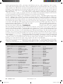
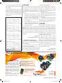
Noise with Q1 sample(7):
NBW
out µV RMS in nV RMS
20kHz-100kHz 22.31
223.1
1kHz-100kHz
24.79
247.9
1kHz-20kHz
10.81
108.1
20Hz-20kHz
11.76
117.6
“A”
9.78
97.8
20Hz-1kHz
4.63
46.3
In, average nV/√Hz
0.789
0.788
0.784
0.832
per FET
average nV/√Hz
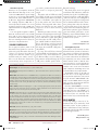
-140.2dBV to -136.7dBV. The
average is -138.4dBV.
CONCLUSION
Compared to my 2006 order (in
which three of the ten units had
out-of-spec noise), all 20 units
1.479
2.012
of my 2007 order were comfortwith Q1 sample (7)
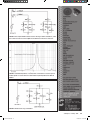
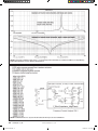
Frequency response: -3dB BW = 1.4Hz – 800kHz
ably within the noise spec.
1kHz gain = 10.0032
1kHz maximum out = 5.14V RMS
Linear Systems offers low(100.027 regarding Q1 gates)
Vo DC = -2.0mV
noise screening for a fee (I don’t
v+ = +10.64V, 20.1mA
**Both FETs combined
V- = -10.29V, 8.6mA
*lot JF300-4-3
yet know the cost), but if these
Q1 Vd = +4.748V, io = 11.56mA**
date code 0447
20 units are representative, that
shouldn’t be necessary.
If you build the LP797 phono preamp,
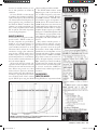
Noise Versus Current
Summary From Table 1 Data I recommend using the specified DIP
Correlation Graph
Here, I’ll use the average values of the sockets for the JFETs. Then, by shorting
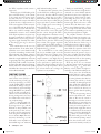
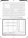
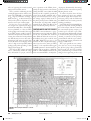
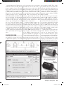
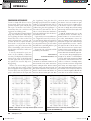
Figure 3 contains 20 circled points, num- 20 samples: Integrated noise voltages of the preamp inputs and measuring the
bered with the LSK389B test samples. the two paralleled FETs with the 10Ω output noise, you can select JFETs for
The horizontal scale is the per-FET source resistor are 145.355nV (20Hz- lowest noise. For small-quantity orders
operating current (Io), and the vertical 20kHz BW ) and 126.655nV (1kHz- from Linear Systems, it probably costs
scale is the 1kHz-20kHz noise volt- 20kHz BW ). RMS subtracting these less to buy a few extra JFETs (so you can
age density of the FET (for each one gives 71.320nV; this is the integrated select the lowest noise units) than to pay
in the package). If a single FET were (total) noise in a 20Hz-1kHz band. Di- Linear Systems for noise screening.
thus plotted over a range of currents, the viding this by √980Hz gives a noise denAt this point, I’d say that the LSK389B
graph would be a downsloping curve, sity of 2.278nV/√Hz, averaged over the is an excellent product, very suitable for
because (within limits) increasing cur- 20Hz-1kHz band.
low-noise audio applications.
aX
rent increases transconductance because
Then, RMS subtracting the
the FET’s channel resistance becomes 0.4057nV/√Hz thermal noise of the
lower. This reduces thermal noise volt- 10Ω resistor, and multiplying the result
age.
by √2 for each FET of the paralleled
But in Fig. 3 the 20 points are fair- pair, gives 3.170nV/√Hz average noise
ly randomly scattered. There is a small voltage density in a 20Hz-1kHz band,
amount of lower-noise versus higher- for a single FET, at an average current
current correlation, but obviously other of 5.44mA. This is 8.7dB higher than
semiconductor physics effects influence the 1.165nV/√Hz figure averaged over
the noise level. Notice, though, sam- the 1kHz-20kHz band. This reflects the
ples #2 and #16: unit #2 has the highest normal low-frequency noise increase of
noise and lowest current, while it’s vice semiconductors, FET and bipolar.
However, as the “A” weighting curve
versa for #16.
shows, the ear is relatively insensitive to
Parts List
low-level, low-frequency sounds.
C1
C2
C3
C4
C5, C6
C7
J1
J2
LED1
LED2
Q1
R1
R2
R3
R4
R5, R8
R6
R7
R9
R10
R11, R12
S1
U1
1000µF
10.9µF
470P
68pF
2N2
100µF
IN
OUT
67-1612
516-1358
LSK389B
9K435
1K0484
509.8
9.99
180
1.067K
46.5K
217.3
549.4
10K
Switch SPST
AD797
0.951
1.029
“A” Weighted Noise
This data in Table 1 ranges from 97.4145.8nV RMS, with an average (of the 20
samples) of 120.47nV RMS. This is for
the as-tested configuration of two paralleled FETs and the 10Ω source resistor.
Calculation of the “A” noise for a single
FET (without source resistor) is difficult
without knowing the resistor’s “A” weighted noise, and will not be estimated here.
But because the as-tested configuration has proven to have reliable low-noise
performance, the above “A” weighted input-referred noise voltage measurements
are relevant. These levels range from
audioXpress February 2009
Colin2933.indd 27
27
12/23/2008 1:38:21 PM