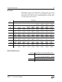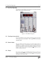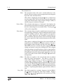
1
Operation and Service Manual
AC Resistance Bridge
SIM921
Stanford Research Systems
Revision 2.3 • September 12, 2011
Certification
Stanford Research Systems certifies that this product met its published specifications at the time
of shipment.
Warranty
This Stanford Research Systems product is warranted against defects in materials and workmanship for a period of one (1) year from the date of shipment.
Service
For warranty service or repair, this product must be returned to a Stanford Research Systems
authorized service facility. Contact Stanford Research Systems or an authorized representative
before returning this product for repair.
Information in this document is subject to change without notice.
c Stanford Research Systems, Inc., 2003 – 2011. All rights reserved.
Copyright Stanford Research Systems, Inc.
1290–D Reamwood Avenue
Sunnyvale, CA 94089 USA
Phone: (408) 744-9040 • Fax: (408) 744-9049
www.thinkSRS.com • e-mail: [email protected]
Printed in U.S.A.
Document number 9-01555-903
SIM921
AC Resistance Bridge
Contents
General Information
Service . . . . . .
Symbols . . . . .
Notation . . . . .
Specifications . .
1
2
3
.
.
.
.
.
.
.
.
.
.
.
.
.
.
.
.
.
.
.
.
.
.
.
.
.
.
.
.
.
.
.
.
.
.
.
.
.
.
.
.
.
.
.
.
Getting Started
1.1 Introduction to the Instrument
1.2 Front-Panel Operation . . . . .
1.3 Sensor Interface . . . . . . . . .
1.4 SIM Interface . . . . . . . . . . .
Remote Operation
2.1 Index of Commands . . . . .
2.2 Alphabetic List of Commands
2.3 Introduction . . . . . . . . . .
2.4 Commands . . . . . . . . . . .
2.5 Status Model . . . . . . . . . .
.
.
.
.
.
.
.
.
.
.
.
.
.
.
.
.
.
.
.
.
.
.
.
.
.
.
.
.
.
.
.
.
.
.
.
.
.
.
.
.
.
.
.
.
.
.
.
.
.
.
.
.
.
.
.
.
.
.
.
.
.
.
.
.
.
.
.
.
.
.
.
.
.
.
.
.
.
.
.
.
.
.
.
.
.
.
.
.
.
.
.
.
.
.
.
.
.
.
.
.
.
.
.
.
.
.
.
.
.
.
.
.
.
.
.
.
.
.
.
.
.
.
.
.
.
.
.
.
.
.
.
.
.
.
.
.
.
.
.
.
.
.
.
.
.
.
.
.
iii
iii
iv
v
vi
.
.
.
.
.
.
.
.
.
.
.
.
1–1
. 1–2
. 1–3
. 1–8
. 1 – 11
.
.
.
.
.
2–1
. 2–2
. 2–4
. 2–7
. 2–8
. 2 – 26
Circuitry
3.1 Circuit Discussion . . . . . . . . . . . . . . . . . . . .
3.2 Parts Lists . . . . . . . . . . . . . . . . . . . . . . . .
3.3 Schematic Diagrams . . . . . . . . . . . . . . . . . .
3–1
. 3–2
. 3–6
. 3–8
i
ii
Contents
SIM921
AC Resistance Bridge
General Information
The SIM921 AC Resistance Bridge, part of Stanford Research Sysetems’ Small Instrumentation Modules family, is a precision, highsensitivity instrument designed for ultra-low power resistance measurements, typically for cryogenic thermometry.
Service
Do not install substitute parts or perform any unauthorized modifications to this instrument.
The SIM921 is a double-wide module designed to be used inside the
SIM900 Mainframe. Do not turn on the power until the module is
completely inserted into the mainframe and locked in place.
iii
iv
General Information
Symbols you may Find on SRS Products
Symbol
Description
Alternating current
Caution - risk of electric shock
Frame or chassis terminal
Caution - refer to accompanying documents
Earth (ground) terminal
Battery
Fuse
On (supply)
Off (supply)
SIM921 AC Resistance Bridge
General Information
v
Notation
The following notation will be used throughout this manual.
WARNING
A warning means that injury or death is possible if the instructions
are not obeyed.
CAUTION
A caution means that damage to the instrument or other equipment
is possible.
Typesetting conventions used in this manual are:
• Front-panel buttons are set as [Button];
[Adjust ] is shorthand for “[Adjust ] & [Adjust ]”.
• Front-panel indicators are set as Overload.
• Remote command names are set as *IDN?.
• Literal text other than command names is set as OFF.
Remote command examples will all be set in monospaced font. In
these examples, data sent by the host computer to the SIM921 are set
as straight teletype font, while responses received by the host
computer from the SIM921 are set as slanted teletype font.
SIM921
AC Resistance Bridge
vi
General Information
Specifications
Performance Characteristics
Measurement
Measurement type
Number of inputs
Resistance range
Time constant
Reading rate
Demodulator resolution
Resolution
Accuracy (% reading + % range)
2 Ω to 200 kΩ, ≥ 30 µV, ≥ 3 nA
200 mΩ to 2 MΩ, ≥ 100 pA
Stability
after autocal
without autocal
Max. lead resistance
Input impedance
Source
Type
Frequency
Excitation
Max. DC current
Thermometry
Analog Output
Operating
Sensors supported
4 wire AC bridge
1
1 mΩ to 100 MΩ
0.3 s to 300 s,
or sync. only
2 updates/s
32-bit
see table
±(0.05 % + 0.05 %)
±(0.15 % + 0.15 %)
(±0.001 % of reading)/◦ C
(±0.02 % of reading)/◦ C
100 Ω + 25 % range
> 10 GΩ, typical
Sinusoid, constant I,V, or P
2 Hz to 60 Hz,
continuously adjustable
3 µV to 30 mV, 10 mA max.
< 3 µV/range
Temperature units
Low temperature
Sensor cal. curves
All resistive sensors
(− and + tempco)
mK, K
∼50 mK, sensor dependent
3 curves of 200 points each
Range
Resolution
Accuracy
±10 V
300 µV
1 mV
Temperature
Interface
Connectors
Sensor
Analog out
SIM
Power
Supply current
0 ◦ C to 40 ◦ C, non-condensing
Serial via SIM interface
DB–9 (female)
BNC (front)
DB–15 (male) SIM Interface
±15 VDC, +5 VDC
150 mA (±15 V), 250 mA (+5 V)
SIM921
AC Resistance Bridge
General Information
vii
Resolution
Resolution is given in the table below. Upper values give excitation current, while lower values are typical RMS resistance noise
measured at 50 % full scale on a room-temperature resistor with a
3 second output time constant.
Range
20 mΩ
30 mV
N/A
10 mV
N/A
3 mV
N/A
1 mV
N/A
200 mΩ
N/A
N/A
N/A
2Ω
N/A
10 mA
4.3 µΩ
1 mA
21 µΩ
100 µA
200 µΩ
10 µA
2.0 mΩ
1 µA
25 mΩ
100 nA
350 mΩ
10 nA
5.9 Ω
1 nA
190 Ω
3 mA
5.5 µΩ
300 µA
33 µΩ
30 µA
370 µΩ
3 µA
2.9 mΩ
300 nA
31 mΩ
30 nA
640 mΩ
3 nA
16 Ω
300 pA
540 Ω
10 mA
8.9 µΩ
1 mA
7.9 µΩ
100 µA
41 µΩ
10 µA
430 µΩ
1 µA
4.0 mΩ
100 nA
56 mΩ
10 nA
1.4 Ω
1 nA
46 Ω
100 pA
1.1 kΩ
20 Ω
200 Ω
2 kΩ
20 kΩ
200 kΩ
2 MΩ
20 MΩ
3 mA
20 µΩ
300 µA
200 µΩ
30 µA
2.0 mΩ
3 µA
20 mΩ
300 nA
250 mΩ
30 nA
3.4 Ω
3 nA
50 Ω
Excitation
300 µV
100 µV
N/A
10 mA
44 µΩ
3 mA
1 mA
12 µΩ
32 µΩ
300 µA
100 µA
23 µΩ
70 µΩ
30 µA
10 µA
100 µΩ 390 µΩ
3 µA
1 µA
1.1 mΩ 2.8 mΩ
300 nA
100 nA
12 mΩ
40 mΩ
30 nA
10 nA
200 mΩ 640 mΩ
3 nA
1 nA
4.5 Ω
16 Ω
300 pA
100 pA
190 Ω
480 Ω
30 pA
10 pA
5.4 kΩ
12 kΩ
30 µV
3 mA
130 µΩ
300 µA
120 µΩ
30 µA
220 µΩ
3 µA
1.7 mΩ
300 nA
9.7 mΩ
30 nA
120 mΩ
3 nA
2.4 Ω
300 pA
47 Ω
30 pA
1.7 kΩ
3 pA
56 kΩ
10 µV
1 mA
510 µΩ
100 µA
590 µΩ
10 µA
730 µΩ
1 µA
4.1 mΩ
100 nA
25 mΩ
10 nA
300 mΩ
1 nA
5.3 Ω
100 pA
150 Ω
10 pA
5.4 kΩ
1 pA
180 kΩ
3 µV
300 µA
1.5 mΩ
30 µA
1.4 mΩ
3 µA
1.8 mΩ
300 nA
10 mΩ
30 nA
120 mΩ
3 nA
900 mΩ
300 pA
23 Ω
30 pA
710 Ω
3 pA
15 kΩ
300 fA
750 kΩ
General Characteristics
Interface
Connectors
Weight
Dimensions
SIM921
AC Resistance Bridge
Serial (RS-232) through SIM interface
DB–9 (female)
AC 4–wire measurement + ground
DB–15 (male) SIM interface
1.4 lbs
1.500 W × 3.600 H × 7.000 D
viii
General Information
SIM921
AC Resistance Bridge
1
Getting Started
This chapter gives the user the necessary information to get started
quickly with the SIM921 AC Resistance Bridge.
In This Chapter
1.1
1.2
1.3
1.4
Introduction to the Instrument . .
1.1.1 Overview . . . . . . . . . .
Front-Panel Operation . . . . . . .
1.2.1 Resetting to factory defaults
1.2.2 Numeric display . . . . . .
1.2.3 Display . . . . . . . . . . . .
1.2.4 Range . . . . . . . . . . . .
1.2.5 Excite . . . . . . . . . . . . .
1.2.6 Output . . . . . . . . . . . .
1.2.7 Autocal . . . . . . . . . . . .
Sensor Interface . . . . . . . . . . .
1.3.1 Four-wire measurement . .
1.3.2 Two-wire measurement . .
1.3.3 Wiring for high impedance
SIM Interface . . . . . . . . . . . .
1.4.1 SIM interface connector . .
1.4.2 Direct interfacing . . . . . .
.
.
.
.
.
.
.
.
.
.
.
.
.
.
.
.
.
.
.
.
.
.
.
.
.
.
.
.
.
.
.
.
.
.
.
.
.
.
.
.
.
.
.
.
.
.
.
.
.
.
.
.
.
.
.
.
.
.
.
.
.
.
.
.
.
.
.
.
.
.
.
.
.
.
.
.
.
.
.
.
.
.
.
.
.
.
.
.
.
.
.
.
.
.
.
.
.
.
.
.
.
.
.
.
.
.
.
.
.
.
.
.
.
.
.
.
.
.
.
.
.
.
.
.
.
.
.
.
.
.
.
.
.
.
.
.
.
.
.
.
.
.
.
.
.
.
.
.
.
.
.
.
.
.
.
.
.
.
.
.
.
.
.
.
.
.
.
.
.
.
.
.
.
.
.
.
.
.
.
.
.
.
.
.
.
.
.
1–2
1–2
1–3
1–3
1–3
1–3
1–5
1–6
1–7
1–7
1–8
1–9
1–9
1–9
1 – 11
1 – 11
1 – 11
1–1
1–2
1.1
Getting Started
Introduction to the Instrument
The SIM921 AC Resistance Bridge monitors a single resistive
sample—typically a cryogenic thermometer—with an adjustable
AC current. With achievable excitation power below 100 aW, selfheating errors can be routinely eliminated.
1.1.1
Overview
The SIM921 uses a half-bridge topology, where the excitation current
is passed through both an internal, stable reference resistor, RR , and
the user’s resistive thermometer, RM (see Figure 1.1). Eight separate
reference resistors, from 1 Ω to 10 MΩ, are built into the instrument,
with two expanded scales (200 mΩ and 20 mΩ) implemented with
additional gain.
The basic measurement is made by a pair of dual-phase demodulators to recover the vector AC voltage (amplitude and phase) developed across the internal reference resistor, VR ) and across the user’s
resistor under measurement, VM . The SIM921 determines the user’s
resistance value ratiometrically from
RM =
|VM |2
× RR
VR • VM
By taking the in-phase component of VR in the ratio, the measurement is largely insensitive to capacitive loads in parallel with the RM ;
the phase shift they introduce is corrected in the denominator.
×1
10 R REF
IX
I SIG
R REF
I
IY
+90°
1
4
5
×−1
11 R REF
VX
V SIG
RM
V
VY
+90°
Low Pass
Filter
2
V
RM =
I
2
R REF
V
Figure 1.1: Block diagram of the SIM921.
SIM921
AC Resistance Bridge
1.2
1.2
Front-Panel Operation
1–3
Front-Panel Operation
The front panel of the SIM921 is divided into several major functional
blocks, each of which will be discussed.
Figure 1.2: The SIM921 front panel.
1.2.1
Resetting to factory defaults
To reset the SIM921 to factory defaults, hold [Set ] depressed while
turning power on to the module. This is equivalent to the remote
command *RST.
1.2.2
Numeric display
The upper block of the front panel is the numeric display field. In
addition to 5 1/2 digits, six units LEDs (mΩ, Ω, kΩ, MΩ, mK, and
K ) indicate the physical units of the quantity displayed. The two
buttons to the left of the numeric display, [Set ], allow the user to
modify settable parameters.
1.2.3
Display
Directly beneath [Set ] is the DISPLAY block of the panel. The two
buttons at the bottom of this section, [Display ], select the quantity
for display in the numeric field.
SIM921
AC Resistance Bridge
1–4
Getting Started
The selections are:
Value : The measured value of the user’s resistor-under-test is displayed, either in resistance units or temperature units (depending on the units selection, below).
When Value is displayed, pressing [Set ] acts as a short-cut to
reset the output filter. This can be useful to speed settling with
a long time constant after a large resistance change is made, or
after the range or excitation is changed.
Value−Offset : This selection (also known as “deviation”) also displays the
measurement result (either in resistance or temperature units),
but after subtracting the user-settable Offset. Pressing [Set ]
will reset the output filter.
Phase (deg.) : This selection shows the phase angle between measured current and voltage (in degrees), and is an indication of how much
capacitive loading is present. Phase is positive for capacitive
loads. A phase angle near +90◦ should be viewed with caution: this indicates that most of the current is flowing through
the reactive part of the load, and measurement accuracy may
suffer.
When phase is displayed, [Set ] can be used to modify the
model used in the SIM921 to determine resistance. By pressing [Set ], the numeric display will show the word:
.
This forces the meter to assume the phase angle between the
voltage and current is zero when solving for R. This is helpful
when measuring very small resistances (such as superconducting samples), since the phase determination becomes otherwise
ill-conditioned when the voltage signal approaches zero, and
causes excess noise in the results. Pressing [Set ] restores normal operation.
Offset : The offset, or setpoint, is the user-selected value to subtract
from the sensor measurement. The offset is used in the
Value−Offset display (above), as well as to determine the
analog output voltage (see below). The [Set ] buttons will
accelerate through multiple digits to adjust the offset; two short
cuts also exist. If both [Set ] and [Set ] are pressed simultaneously, Offset is preloaded with the latest measurement result
of Value. Depressing both buttons again will force Offset to
zero.
Freq. (Hz) : This field controls the excitation frequency for the SIM921.
[Set ] adjusts the frequency from 2 Hz to 60 Hz. Depressing both [Set ] and [Set ] together will step between 15 Hz,
10 Hz, 5 Hz, and 2.5 Hz.
SIM921
AC Resistance Bridge
1.2
Front-Panel Operation
1–5
AOUT : This parameter is the slope (in V/Ω or V/K) used to scale the
deviation signal for analog output. Use [Set ] to accelerate
through many orders of magnitude for AOUT ; releasing the
button and re-pressing it allows fine control over the lower
digits, as the setting begins accelerating again. If resistance
units are selected for analog output, the Ω indicator will be lit
next to the numeric display; if temperature units are selected,
the K indicator will be lit.
Units (Ω, K) : This is actually three separate selections that are stepped
through by continuing to press [Display ]. The first selection lights both the Value and Units indicators. This selects
either resistance or temperature units for the Value display.
Use [Set ] to switch between resistance (the display will show
) and temperature (the display will show the ID message
of the selected sensor calibration curve).
Pressing [Display ] again will light AOUT and Units together.
Now, [Set ] selects between resistance or temperature units
for the analog output function. Note that the deviation display
and offset parameter units are also determined by AOUT –Units.
Pressing [Display ] one final time will leave Units lit alone.
Now the [Set ] selects among three sensor calibration curves
stored in the SIM921. If a particular curve has not been loaded,
the
is lit to indicate this is not a usable curve; once (at least)
two points are loaded in a sensor curve memory, the display
will show
to the left of the curve ID. Only one curve can be
selected at a time.
1.2.4
Range
The RANGE block of the front panel selects the reference resistor.
Press [Range ] to step between ranges from 20 mΩ to 20 MΩ. For
all ranges ≥ 2 Ω, the reference resistor RR is 1/2 the total range. For
example, on the 20 kΩ range, RR = 10 kΩ. For ranges ≤ 2 Ω, the
RR = 1.0 Ω.
The Autorange subblock controls two independent functions related
to range. Briefly tapping [Autorange] will toggle autorange Display
on and off. When Autorange Display is off, the numeric display
decimal point is fixed based on the selected range. With Autorange
Display on, the decimal point (and possibly the units indicator) shifts
to display the result with maximum resolution.
Holding [Autorange] for ∼2 seconds light Gain and initiate an autogain cycle. Whenever the SIM921 is set to a new range or excitation,
the internal amplifiers are preset to nominal gains. This might not be
SIM921
AC Resistance Bridge
1–6
Getting Started
optimal for measuring resistors that are much smaller than, or larger
than, the nominal range setting. Also, if the user is in a high-noise environment, out-of-band pick-up might cause amplifier saturation. In
either of these cases, initiating an autogain cycle will force the SIM921
to optimize gains for the signals present at that time. Once completed,
the Gain is unlit, and the amplifier gains remain fixed at their new
levels. Changing excitation or range will reset the amplifiers to their
(new) nominal settings.
1.2.5
Excite
The EXCITE block controls the excitation amplitude for the measurement. [Excite ] step between excitation levels in 1–3–10 steps
from 3 µV to 30 mV. It is possible to step the amplitude setting down
once more from the 3 µV setting, setting the excitation amplitude to
zero. Note that this does not close the shunting relay, as On/Off does
(below).
The amplitude, together with the excitation mode, determines the
actual conditions for the measurement. [Mode], at the bottom of
the EXCITE block, is another dual-function control. Briefly tapping
[Mode] toggles the excitation On/Off; when Off, a mechanical relay
shunts the excitation current, preventing any current from flowing
to the user’s resistor.
While the excitation is off, holding [Mode] for ∼2 seconds will step
between four (4) distinct excitation modes:
Constant Current : With Current lit, the SIM921 will operate in constant current
mode. This programs an AC current with rms amplitude of
excite/RR ; for example, if the excitation is set to 100 µV and the
range is 20 kΩ, the excitation current will equal 10 nA (100 µV /
10 kΩ = 10 nA). This is implemented by servoing the measured
voltage across the reference resistor, RR to the selected excitation
amplitude.
Constant Voltage : With Voltage lit, the SIM921 will operate in constant voltage
mode. In this mode, the excitation is servoed to keep the measured voltage across the user’s resistor, RM equal to the selected
excitation. This can be particularly useful for negative tempco
thermometers at low temperatures, where a constant current
would lead to increasing power dissipation at lower temperatures (P = I2 RM , RM ↑, P ↑ as T ↓). With constant voltage,
the ohmic dissipation goes down with decreasing temperature
(P = V 2 /RM , RM ↑, P ↓ as T ↓).
Constant Power : With both Current and Voltage lit, the SIM921 servoes the
excitation to keep the power dissipated in the user’s resistor
SIM921
AC Resistance Bridge
1.2
Front-Panel Operation
1–7
constant, at the level V 2 /(RR /2).
Passive : With neither indicator lit, the SIM921 disables excitation servoing, and simply sets a fixed AC amplitude across the entire
bridge circuit. The amplitude is set so that for RM up to about
the 2RR , the current will approximately equal the corresponding constant-current setting (above). For user resistances much
larger than the range setting (RM RR ), the voltage across the
user resistor will approach ∼ 20× the nominal excitation (see
Figure 1.1).
1.2.6
Output
The OUTPUT block of the front panel selects the post-detection filter
setting, and contains the BNC connector for the analog output. The
filter is a simple 6 dB/octave low pass filter that calculates a running
exponential average of the vector voltages (prior to the ratio calculation). Higher settings of the time constant will reduce measurement
noise at the expense of slower settling times. The filter affects the
display values as well as the analog output voltages.
[Time Const. ]step the filter time constant in 1–3–10 steps from
0.3 s to 300 s. Stepping the time constant downwards from 0.3 s
turns off the 6 dB/octave filter completely, leaving only a running
boxcar “sync” filter (that averages the signals over the one excitation
period) active. The sync filter effectively eliminates the 2 × f signals
from the demodulator output, but otherwise provides little noise
reduction. This is an appropriate setting for relatively high signalto-noise measurements where signal bandwidth is important.
It can take six or seven time constants for the output of the SIM921
to fully settle after a step change; for slow time constant settings, this
can be a bothersome delay. The filter can be reset by pressing [Set ]
when the display is Value or Value−Offset.
1.2.7
Autocal
The AUTOCAL block controls the internal autocalibration of the
SIM921Ȧutocalibration cross-calibrates the relative gain of the two
amplifier chains in the system. The process takes about three (3)
minutes to complete, and can be started by holding [Autocal] for
∼2 seconds. A countdown is displayed to indicate approximate time
remaining. The autocalibration can be aborted by pressing [Autocal]
again before the cycle completes—this will abandon the calibration
in progress, and revert to the previous calibration values.
SIM921
AC Resistance Bridge
1–8
1.3
Getting Started
Sensor Interface
The sensor interface on the SIM921 consists a rear-panel DB–9/F connector, labeled “INPUT” (see Figure 1.3). The pin assignments for
this connector are given in Table 1.1.
Pin
1
2
3
4
5
6
7
8
9
Signal
I+ (current lead)
I− (current lead)
ground
V+ (voltage lead)
V− (voltage lead)
ground
ground
ground
ground
Table 1.1: SIM921 Sensor Interface Connector Pins, DB–9. Drawing
shows pin numbers looking into the rear of the instrument.
Figure 1.3: The SIM921 rear panel.
SIM921 AC Resistance Bridge
1.3
1.3.1
Sensor Interface
1–9
Four-wire measurement
To avoid sensitivity to wiring lead resistance, the SIM921 is configured for four-wire measurements. The basic circuit for this wiring
scheme is shown in Figure 1.4.
I+
V+
Sensor
V–
I–
Figure 1.4: Wiring diagram for four-wire readout.
1.3.2
Two-wire measurement
If application-specific constraints limit the number of leads to the
sensor, the SIM921 can be wired to measure the sensor resistance
with a simple two-wire circuit, shown in Figure 1.5. Note that the
lead resistance (past the junction points of the current and voltage
leads) will add as a direct resistance error when measuring the sensor.
I+
V+
Sensor
V–
I–
Figure 1.5: Wiring diagram for two-wire readout.
1.3.3
Wiring for high impedance
When using the SIM921 to measure high impedances (> few MΩ),
cable construction becomes crucial. It is important that the wire
leads have a low-loss dielectric insulation, such as PTFE (TeflonTM ).
Ordinary PVC-insulated wire is not well suited to this application,
as it can suffer from dielectric absorption effects. Regardless of a
SIM921
AC Resistance Bridge
1 – 10
Getting Started
very high DC insulation resistance (> 100 GΩ), small AC dielectric
losses, even at the low frequencies used by the SIM921, can appear
as (10s∼100s) MΩ of real impedance in parallel with the user load.
SIM921
AC Resistance Bridge
1.4
1.4
SIM Interface
1 – 11
SIM Interface
The primary connection to the SIM921 AC Resistance Bridge is the
rear-panel DB–15 SIM interface connector. Typically, the SIM921 is
mated to a SIM900 Mainframe via this connection, either through
one of the internal mainframe slots, or the remote cable interface.
It is also possible to operate the SIM921 directly, without using the
SIM900 Mainframe. This section provides details on the interface.
CAUTION
1.4.1
The SIM921 has no internal protection against reverse polarity, missing
supply, or overvoltage on the power supply pins. Misapplication of power
may cause circuit damage. SRS recommends using the SIM921 together
with the SIM900 Mainframe for most applications.
SIM interface connector
The DB–15 SIM interface connector carries all the power and communications lines to the instrument. The connector signals are specified
in Table 1.2
Pin
1
2
3
4
5
6
7
8
9
10
11
12
13
14
15
Direction
Src ⇒ Dest
Signal
SIGNAL GND
−STATUS
RTS
CTS
−REF 10MHZ
−5 V
−15 V
PS RTN
CHASSIS GND
TXD
RXD
+REF 10MHz
+5 V
+15 V
+24 V
MF ⇒ SIM
SIM ⇒ MF
MF ⇒ SIM
SIM ⇒ MF
MF ⇒ SIM
MF ⇒ SIM
MF ⇒ SIM
MF ⇒ SIM
MF ⇒ SIM
SIM ⇒ MF
MF ⇒ SIM
MF ⇒ SIM
MF ⇒ SIM
MF ⇒ SIM
Description
Ground reference for signal
Status/service request (GND = asserted, +5 V= idle)
HW handshake (+5 V= talk; GND = stop)
HW handshake (+5 V= talk; GND = stop)
10 MHz reference (optional connection)
Power supply (no connection in SIM921)
Power supply (analog circuitry)
Power supply return
Chassis ground
Async data (start bit = “0”= +5 V; “1” = GND)
Async data (start bit = “0”= +5 V; “1” = GND)
10 MHz reference (optional connection)
Power supply (digital circuitry)
Power supply (analog circuitry)
Power supply (no connection in SIM921)
Table 1.2: SIM Interface Connector Pin Assignments, DB-15
1.4.2
Direct interfacing
The SIM921 is intended for operation in the SIM900 Mainframe, but
users may wish to directly interface the module to their own systems
without the use of additional hardware.
SIM921
AC Resistance Bridge
1 – 12
Getting Started
The mating connector needed is a standard DB–15 receptacle, such as
Amp part # 747909-2 (or equivalent). Clean, well-regulated supply
voltages of +5, ±15 VDC must be provided, following the pin-out
specified in Table 1.2. Ground must be provided on pins 1 and 8,
with chassis ground on pin 9. The −STATUS signal may be monitored
on pin 2 for a low-going TTL-compatible output indicating a status
message.
1.4.2.1
Direct interface cabling
If the user intends to directly wire the SIM921 independent of the
SIM900 Mainframe, communication is usually possible by directly
connecting the appropriate interface lines from the SIM921 DB–15
plug to the RS-232 serial port of a personal computer.1 Connect RXD
from the SIM921 directly to RD on the PC, TXD directly to TD, and
similarly RTS→RTS and CTS→CTS. In other words, a null-modem
style cable is not needed.
To interface directly to the DB–9 male (DTE) RS-232 port typically
found on contemporary personal computers, a cable must be made
with a female DB–15 socket to mate with the SIM921, and a female
DB–9 socket to mate with the PC’s serial port. Separate leads from
the DB–15 need to go to the power supply, making what is sometimes
know as a “hydra” cable. The pin-connections are given in Table 1.3.
DB–15/F to SIM921
DB–9/F
10 ←→ 3
11 ←→ 2
5
Name
TxD
RxD
Computer Ground
to P/S
7 ←→ −15 VDC
14 ←→ +15 VDC
13 ←→ +5 VDC
8,9 ←→ Ground (P/S return current)
1 ←→ Signal Ground (separate wire to Ground)
Table 1.3: SIM921 Direct Interface Cable Pin Assignments
1
Although the serial interface lines on the DB-15 do not satisfy the minimum
voltage levels of the RS-232 standard, they are typically compatible with desktop
personal computers
SIM921
AC Resistance Bridge
1.4
SIM Interface
1.4.2.2
1 – 13
Serial settings
The serial port settings at power-on are: 9600 baud, 8–bits, no parity,
1 stop bit, and no flow control (see Section 2.3.1). The serial settings
cannot be changed on the SIM921.
SIM921
AC Resistance Bridge
1 – 14
Getting Started
SIM921
AC Resistance Bridge
2
Remote Operation
This chapter describes operating the SIM921 over the serial interface.
In This Chapter
2.1
2.2
2.3
2.4
2.5
Index of Commands . . . . . . . . . . . . . . . . . .
Alphabetic List of Commands . . . . . . . . . . . .
Introduction . . . . . . . . . . . . . . . . . . . . . . .
2.3.1 Power-on configuration . . . . . . . . . . . .
2.3.2 Buffers . . . . . . . . . . . . . . . . . . . . . .
2.3.3 Device Clear . . . . . . . . . . . . . . . . . . .
Commands . . . . . . . . . . . . . . . . . . . . . . .
2.4.1 Command syntax . . . . . . . . . . . . . . . .
2.4.2 Notation . . . . . . . . . . . . . . . . . . . . .
2.4.3 Examples . . . . . . . . . . . . . . . . . . . .
2.4.4 Excitation commands . . . . . . . . . . . . .
2.4.5 Measurement commands . . . . . . . . . . .
2.4.6 Post-detection processing commands . . . .
2.4.7 Calibration curve commands . . . . . . . . .
2.4.8 Autoranging commands . . . . . . . . . . . .
2.4.9 Autocalibration command . . . . . . . . . . .
2.4.10 Setpoint and analog output commands . . .
2.4.11 Interface commands . . . . . . . . . . . . . .
2.4.12 Status commands . . . . . . . . . . . . . . . .
Status Model . . . . . . . . . . . . . . . . . . . . . .
2.5.1 Status Byte (SB) . . . . . . . . . . . . . . . . .
2.5.2 Service Request Enable (SRE) . . . . . . . . .
2.5.3 Standard Event Status (ESR) . . . . . . . . .
2.5.4 Standard Event Status Enable (ESE) . . . . .
2.5.5 Communication Error Status (CESR) . . . . .
2.5.6 Communication Error Status Enable (CESE)
2.5.7 Overload Status (OVCR) . . . . . . . . . . . .
2.5.8 Overload Status (OVSR) . . . . . . . . . . . .
2.5.9 Overload Status Enable (OVSE) . . . . . . . .
.
.
.
.
.
.
.
.
.
.
.
.
.
.
.
.
.
.
.
.
.
.
.
.
.
.
.
.
.
2–2
2–4
2–7
2–7
2–7
2–7
2–8
2–8
2–9
2–9
2 – 10
2 – 12
2 – 14
2 – 15
2 – 17
2 – 17
2 – 17
2 – 18
2 – 23
2 – 26
2 – 27
2 – 28
2 – 28
2 – 29
2 – 29
2 – 30
2 – 30
2 – 31
2 – 31
2–1
2–2
2.1
Remote Operation
Index of Commands
symbol
i,j
f ,g
z
s
definition
Integers
Floating-point values
Literal token
Arbitrary character sequence (no “,” or “;”)
(?)
var
{var}
[var]
Required for queries; illegal for set commands
Parameter always required
Required parameter for set commands; illegal for queries
Optional parameter for both set and query forms
Excitation
FREQ(?) {f }
RANG(?) {i}
EXCI(?) {i}
EXON(?) {z}
MODE(?) {z}
IEXC?
VEXC?
2 – 10
2 – 10
2 – 11
2 – 11
2 – 11
2 – 11
2 – 11
Frequency
Range
Excitation
Excitation On/Off
Excitation Mode
Query Excitation Current
Query Excitation Voltage
Measurement
RVAL? [i]
RDEV? [i]
TVAL? [i]
TDEV? [i]
PHAS? [i]
TPER(?) {i}
SOUT
DISP(?) {i}
2 – 12
2 – 12
2 – 12
2 – 13
2 – 13
2 – 13
2 – 13
2 – 14
Resistance Value
Resistance Deviation
Temperature Value
Temperature Deviation
Phase
Time Period for Streaming
Stop Streaming
Display
Post-Detection
FRST
TCON(?) {i}
PHLD(?) {z}
2 – 14 Filter Reset
2 – 14 Time Constant
2 – 15 Phase Hold
CalCurves
DTEM(?) {z}
ATEM(?) {z}
CURV(?) {i}
CINI(?) i {,z,s}
CAPT i,f,g
CAPT? i,j
2 – 15
2 – 15
2 – 15
2 – 16
2 – 16
2 – 16
Display Temperature
Analog Output Temperature
Sensor Calibration Curve
Initialize Sensor Calibration
Add Point to Sensor Calibration
Query Point in Sensor Calibration
SIM921
AC Resistance Bridge
2.1
Index of Commands
SIM921
2–3
Autorange
AGAI(?) {z}
ADIS(?) {z}
2 – 17 Autorange Gain
2 – 17 Autorange Display
Autocalibration
ACAL
2 – 17 Autocalibration
Setpoint/Analog Output
RSET(?) {f }
2 – 17
TSET(?) {f }
2 – 18
VOHM(?) {f }
2 – 18
VKEL(?) {f }
2 – 18
AMAN(?) {z}
2 – 18
AOUT(?) {f }
2 – 18
Resistance Setpoint
Temperature Setpoint
Analog Output Scale (V/Ω)
Analog Output Scale (V/K)
Analog Output Manual Mode
Analog Output Manual Value
Interface
*RST
*IDN?
*TST?
*OPC(?)
CONS(?) {z}
LEXE?
LCME?
LBTN?
TOKN(?) {z}
TERM(?) {z}
2 – 19
2 – 20
2 – 20
2 – 20
2 – 20
2 – 21
2 – 21
2 – 22
2 – 22
2 – 22
Reset
Identify
Self Test
Operation Complete
Console Mode
Execution Error
Command Error
Button
Token Mode
Response Termination
Status
*STB? [i]
*SRE(?) [i,] {j}
*CLS
PSTA(?) {z}
*ESR? [i]
*ESE(?) [i,] {j}
CESR? [i]
CESE(?) [i,]{j}
OVCR? [i]
OVSR? [i]
OVSE(?) [i,]{j}
2 – 23
2 – 23
2 – 23
2 – 23
2 – 24
2 – 24
2 – 24
2 – 24
2 – 24
2 – 24
2 – 25
Status Byte
Service Request Enable
Clear Status
Pulsed Status Mode
Standard Event Status
Standard Event Status Enable
Communication Error Status
Communication Error Status Enable
Overload Condition
Overload Status
Overload Status Enable
AC Resistance Bridge
2–4
2.2
Remote Operation
Alphabetic List of Commands
?
*CLS
*ESE(?) [i,] {j}
*ESR? [i]
*IDN?
*OPC(?)
*RST
*SRE(?) [i,] {j}
*STB? [i]
*TST?
2 – 23
2 – 24
2 – 24
2 – 20
2 – 20
2 – 19
2 – 23
2 – 23
2 – 20
Clear Status
Standard Event Status Enable
Standard Event Status
Identify
Operation Complete
Reset
Service Request Enable
Status Byte
Self Test
2 – 17
2 – 17
2 – 17
2 – 18
2 – 18
2 – 15
Autocalibration
Autorange Display
Autorange Gain
Analog Output Manual Mode
Analog Output Manual Value
Analog Output Temperature
2 – 16
2 – 16
2 – 24
2 – 24
2 – 16
2 – 20
2 – 15
Add Point to Sensor Calibration
Query Point in Sensor Calibration
Communication Error Status Enable
Communication Error Status
Initialize Sensor Calibration
Console Mode
Sensor Calibration Curve
A
ACAL
ADIS(?) {z}
AGAI(?) {z}
AMAN(?) {z}
AOUT(?) {f }
ATEM(?) {z}
C
CAPT i,f,g
CAPT? i,j
CESE(?) [i,]{j}
CESR? [i]
CINI(?) i {,z,s}
CONS(?) {z}
CURV(?) {i}
D
DISP(?) {i}
DTEM(?) {z}
2 – 14 Display
2 – 15 Display Temperature
E
EXCI(?) {i}
EXON(?) {z}
2 – 11 Excitation
2 – 11 Excitation On/Off
F
FREQ(?) {f }
FRST
2 – 10 Frequency
2 – 14 Filter Reset
SIM921
AC Resistance Bridge
2.2
Alphabetic List of Commands
2–5
I
IEXC?
2 – 11 Query Excitation Current
L
LBTN?
LCME?
LEXE?
2 – 22 Button
2 – 21 Command Error
2 – 21 Execution Error
M
MODE(?) {z}
2 – 11 Excitation Mode
O
OVCR? [i]
OVSE(?) [i,]{j}
OVSR? [i]
2 – 24 Overload Condition
2 – 25 Overload Status Enable
2 – 24 Overload Status
P
PHAS? [i]
PHLD(?) {z}
PSTA(?) {z}
2 – 13 Phase
2 – 15 Phase Hold
2 – 23 Pulsed Status Mode
R
RANG(?) {i}
RDEV? [i]
RSET(?) {f }
RVAL? [i]
2 – 10
2 – 12
2 – 17
2 – 12
Range
Resistance Deviation
Resistance Setpoint
Resistance Value
S
SOUT
2 – 13 Stop Streaming
T
TCON(?) {i}
TDEV? [i]
TERM(?) {z}
TOKN(?) {z}
TPER(?) {i}
TSET(?) {f }
TVAL? [i]
2 – 14
2 – 13
2 – 22
2 – 22
2 – 13
2 – 18
2 – 12
Time Constant
Temperature Deviation
Response Termination
Token Mode
Time Period for Streaming
Temperature Setpoint
Temperature Value
V
VEXC?
VKEL(?) {f }
SIM921
AC Resistance Bridge
2 – 11 Query Excitation Voltage
2 – 18 Analog Output Scale (V/K)
2–6
Remote Operation
VOHM(?) {f }
2 – 18 Analog Output Scale (V/Ω)
SIM921
AC Resistance Bridge
2.3
2.3
Introduction
2–7
Introduction
Remote operation of the SIM921 is through a simple command language documented in this chapter. Both set and query forms of most
commands are supported, allowing the user complete control of the
amplifier from a remote computer, either through the SIM900 Mainframe or directly via RS-232 (see Section 1.4.2.1).
See Table 1.2 for specification of the DB–15 SIM interface connector.
2.3.1
Power-on configuration
The settings for the remote interface are 9600 baud with no parity
and no flow control, and local echo disabled (CONS OFF).
Most of the SIM921 instrument settings are stored in non-volatile
memory, and at power-on the instrument returns to the state it was
last in when power was removed. Exceptions are noted in the command descriptions.
Reset values of parameters are shown in boldface.
2.3.2
Buffers
Incoming data from the host interface is stored in a 64-byte input
buffer. Characters accumulate in the input buffer until a command
terminator (either hCRi or hLFi) is received, at which point the message is parsed and executed. Query responses from the SIM921 are
buffered in a 64-byte output queue.
If the input buffer overflows, then all data in both the input buffer
and the output queue are discarded, and an error is recorded in the
CESR and ESR status registers.
2.3.3
Device Clear
The SIM921 host interface can be asynchronously reset to its poweron configuration by sending an RS-232-style hbreaki signal. From the
SIM900 Mainframe, this is accomplished with the SRST command;
if directly interfacing via RS-232, then use a serial break signal. After
receiving the Device Clear, the interface is reset to 9600 baud and
CONS mode is turned OFF. Note that this only resets the communication interface; the basic function of the SIM921 is left unchanged;
to reset the instrument, see *RST.
The Device Clear signal will also terminate any streaming outputs
from the SIM921 due to a TVAL? or RVAL? query of multiple conversions.
SIM921
AC Resistance Bridge
2–8
2.4
Remote Operation
Commands
This section provides syntax and operational descriptions for remote
commands.
2.4.1
Command syntax
The four letter mnemonic (shown in CAPS) in each command sequence specifies the command. The rest of the sequence consists of
parameters.
Commands may take either set or query form, depending on whether
the “?” character follows the mnemonic. Set only commands are
listed without the “?”, query only commands show the “?” after the
mnemonic, and optionally query commands are marked with a “(?)”.
Parameters shown in { } and [ ] are not always required. Parameters in
{ } are required to set a value, and are omitted for queries. Parameters
in [ ] are optional in both set and query commands. Parameters listed
without any surrounding characters are always required.
Do not send ( ) or { } or [ ] as part of the command.
Multiple parameters are separated by commas. Multiple commands
may be sent on one command line by separating them with semicolons (;) so long as the input buffer does not overflow. Commands
are terminated by either hCRi or hLFi characters. Null commands
and whitespace are ignored. Execution of command(s) does not
begin until the command terminator is received.
tokens Token parameters (generically shown as z in the command de-
scriptions) can be specified either as a keyword or integer value.
Command descriptions list the valid keyword options, with each
keyword followed by its corresponding integer value. For example,
to set the response termination sequence to hCRi+hLFi, the following
two commands are equivalent:
TERM CRLF
—or—
TERM 3
For queries that return token values, the return format (keyword or
integer) is specified with the TOKN command.
SIM921
AC Resistance Bridge
2.4
2.4.2
Commands
2–9
Notation
The following table summarizes the notation used in the command
descriptions:
2.4.3
Symbol
i,j
f ,g
z
s
Definition
Integers
Floating-point values
Literal token
Arbitrary character sequence (no “,” or “;”)
(?)
var
{var}
[var]
Required for queries; illegal for set commands
Parameter always required
Required parameter for set commands; illegal for queries
Optional parameter for both set and query forms
Examples
Each command is provided with a simple example illustrating its
usage. In these examples, all data sent by the host computer to
the SIM921 are set as straight teletype font, while responses
received the host computer from the SIM921 are set as slanted
teletype font.
The usage examples vary with respect to set/query, optional parameters, and token formats. These examples are not exhaustive, but are
intended to provide a convenient starting point for user programming.
SIM921
AC Resistance Bridge
2 – 10
2.4.4
Remote Operation
Excitation commands
FREQ(?) {f }
Frequency
Set (query) the excitation frequency {to f Hz}.
The excitation frequency can be set with approximately 10 mHz resolution. The parameter f must be in the range 1.95 ≤ f ≤ 61.1. The
reset value is 10.0.
Example: In the following, the excitation is set to 13.7 Hz.
FREQ 13.7; FREQ?
13.7025
RANG(?) {i}
Range
Set (query) the resistance range {to i}.
Valid range codes are:
i
0
1
2
3
4
5
6
7
8
9
Range
20 mΩ
200 mΩ
2Ω
20 Ω
200 Ω
2 kΩ
20 kΩ
200 kΩ
2 MΩ
20 MΩ
Example: RANG 5
SIM921
AC Resistance Bridge
2.4
Commands
EXCI(?) {i}
2 – 11
Excitation
Set (query) the nominal excitation {to i}.
Valid excitation codes are:
i
-1
0
1
2
3
4
5
6
7
8
Excitation
0 (excitation off)
3 µV
10 µV
30 µV
100 µV
300 µV
1 mV
3 mV
10 mV
30 mV
Example: EXCI?
3
EXON(?) {z}
Excitation On/Off
Set (query) the excitation source {to z=(OFF 0, ON 1)}.
Example: EXON 1
MODE(?) {z}
Excitation Mode
Set (query) the excitation mode {to z=(PASSIVE 0, CURRENT 1,
VOLTAGE 2, POWER 3)}.
Example: TOKN ON; MODE?
PASSIVE
IEXC?
Query Excitation Current
Query the actual excitation current amplitude, in amperes.
Example: IEXC?
+1.043700E-07
VEXC?
Query Excitation Voltage
Query the actual excitation voltage amplitude, in volts. This is the
voltage measured across the sensor itself, not the “nominal” excitation across the entire bridge (set by EXCI).
Example: VEXC?
+1.176760E-05
SIM921
AC Resistance Bridge
2 – 12
2.4.5
Remote Operation
Measurement commands
RVAL? [i]
Resistance Value
Query the measured value of resistance, in ohms.
If the optional i is specified, then i measurement results are returned
to the host, separated by TPER milliseconds. If i=0 is specified, then
streaming of RVAL? results continues indefinitely until the SOUT
command is received.
Example: RVAL? 4
+1.130924E+02
+1.131047E+02
+1.130922E+02
+1.130764E+02
RDEV? [i]
Resistance Deviation
Query the measured value of resistance, in ohms, offset by the resistance setpoint (see RSET).
If the optional i is specified, then i measurement results are returned
to the host, separated by TPER milliseconds. If the optional i is specified, then i measurement results are returned to the host, separated
by TPER milliseconds. If i=0 is specified, then streaming results
continues indefinitely until the SOUT command is received.
Example: RSET 100
RDEV?
+1.308144E+01
TVAL? [i]
Temperature Value
Query the measured value of temperature, in kelvin.
If the optional i is specified, then i measurement results are returned
to the host, separated by TPER milliseconds. If the optional i is specified, then i measurement results are returned to the host, separated
by TPER milliseconds. If i=0 is specified, then streaming results
continues indefinitely until the SOUT command is received.
Example: TVAL?
+3.067459E+02
SIM921
AC Resistance Bridge
2.4
Commands
TDEV? [i]
2 – 13
Temperature Deviation
Query the measured value of temperature, in kelvin, offset by the
temperature setpoint (see TSET).
If the optional i is specified, then i measurement results are returned
to the host, separated by TPER milliseconds. If the optional i is specified, then i measurement results are returned to the host, separated
by TPER milliseconds. If i=0 is specified, then streaming results
continues indefinitely until the SOUT command is received.
Example: TSET 306
TDEV?
+7.345581E-01
PHAS? [i]
Phase
Query the phase of the measured voltage (in degrees) with respect
to the excitation current. Positive angles correspond to capacitive
loads. This query disregards the PHLD setting.
If the optional i is specified, then i measurement results are returned
to the host, separated by TPER milliseconds. If the optional i is specified, then i measurement results are returned to the host, separated
by TPER milliseconds. If i=0 is specified, then streaming results
continues indefinitely until the SOUT command is received.
Example: PHAS?
+0.022
TPER(?) {i}
Time Period for Streaming
Set (query) the time period {to i}, in ms. TPER can be set with 10 ms
resolution in the range 100 ≤ i ≤ 6 555 350. The reset value is 1000.
Example: TPER 500
SOUT
Stop Streaming
Turn off streaming output.
Streaming is also halted by the Device Clear signal (serial break), but
not by *RST.
Example: TDEV?0
+8.273926E-01
+8.048706E-01 SOUT
SIM921
AC Resistance Bridge
2 – 14
Remote Operation
DISP(?) {i}
Display
Set (query) the display selection {to i}.
Valid display codes are:
i
0
1
2
3
4
5
6
7
8
Display
Units
Units+AOUT
Units+Value
AOUT
Freq. (Hz)
Offset
Phase (deg.)
Value−Offset
Value
Example: DISP VALUE
2.4.6
Post-detection processing commands
FRST
Filter Reset
Reset the post-detection filter.
Example: FRST
TCON(?) {i}
Time Constant
Set (query) the time constant for the post-detection filter { to i}.
Valid time constant codes are:
i
-1
0
1
2
3
4
5
6
Time Constant
filter off (sync only)
0.3 s
1s
3s
10 s
30 s
100 s
300 s
Example: TCON 2
SIM921
AC Resistance Bridge
2.4
Commands
PHLD(?) {z}
2 – 15
Phase Hold
Set (query) the phase hold mode {to z=(OFF 0, ON 1)}.
Forces the resistance calculation to assume zero phase. This mode
is useful for measurements of very low resistance (such as superconducting transitions) where the raw signal-to-noise ratio becomes
much less than unity.
Example: PHLD ON
2.4.7
Calibration curve commands
DTEM(?) {z}
Display Temperature
Set (query) the display temperature mode {to z=(OFF 0, ON 1)}.
When ON, the SIM921 display for Value will be in temperature units
instead of resistance.
Example: DTEM?
ON
ATEM(?) {z}
Analog Output Temperature
Set (query) the analog output temperature mode {to z=(OFF 0, ON
1)}.
When ON, the SIM921 generates an analog output proportional to
temperature deviation instead of resistance deviation. Also, the display units for Value−Offset and Offset are set with ATEM.
Example: ATEM?
1
CURV(?) {i}
Sensor Calibration Curve
Set (query) the selected sensor calibration curve {to i}. Valid curve
numbers are 1, 2, and 3. A curve number may be selected with CURV
even if no corresponding curve has been loaded into the SIM921.
Example: CURV?
2
SIM921
AC Resistance Bridge
2 – 16
CINI(?) i {,z,s}
Remote Operation
Initialize Sensor Calibration
Initialize sensor calibration curve i=(1, 2, or 3).
The set form of the command, CINI i,z,s, erases the old contents of
curve i. The second parameter z=(LINEAR 0, SEMILOGT 1, SEMILOGR
2, LOGLOG 3) defines the sensor curve format. The third parameter s is an arbitrary identification string for this sensor calibration
curve. This string can consist of any non-blank characters except
the comma “,” or semicolon “;”, and can be up to 15 characters in
length. The leading 5 characters will be displayed on the SIM921
front panel when the curve is selected, within the limitations of the
seven-segment display hardware.
Example: CINI 3, SEMILOGR, GRT 75
The query form of the command, CINI? i, returns the following response: hformati, hseriali, n
where hformati is the calibration curve format (same as z above),
hseriali is the full identification string for the curve, and n is the
number of points currently stored in the curve.
Example: CINI? 2
LINEAR,PT100,225
CAPT i,f,g
Add Point to Sensor Calibration
Add a new point to sensor calibration curve i. f is the raw sensor
value (in either ohms or log10 (ohms), depending on curve format),
and g is the corresponding temperature value (in either kelvin or
log10 (kelvin), again depending on curve format).
Note that curve points must be added in increasing order of sensor
value f .
Example: CAPT 3, 3.223631, 127.542E-3 In the preceding, a point is added
for R = 1.67352 kΩ, T = 127.542 mK. The curve format is SEMILOGR,
so the raw sensor value transmitted is log10 (1.67352 × 10³ )
CAPT? i,j
Query Point in Sensor Calibration
Query the value of sensor calibration curve i, entry point j.
The response is
hsensori,htemperaturei,
where hsensori is the raw sensor value (in either ohms or log10 (ohms),
depending on curve format), and htemperaturei is the corresponding
temperature value (in either kelvin or log10 (kelvin), again depending
on curve format).
SIM921
AC Resistance Bridge
2.4
Commands
2 – 17
Example: CAPT? 3,45
3.223631E+00,1.275420E-01
2.4.8
Autoranging commands
AGAI(?) {z}
Autorange Gain
Set (query) autoranging of gain {to z=(OFF 0, ON 1)}. When autoranging gain, the SIM921 will optimize signal-to-noise for the current and voltage measurement channels. After autoranging gain
completes, the SIM921 automatically turns AGAI OFF. Nominal gains
are restored by sending the RANG or EXCI commands, with either
the prior setting or a new setting.
Note that if AGAI is commanded off with a remote command prior to
the completion of the autoranging cycle, the internal gains will be left
in an indeterminate state. To restore proprer operation, either re-issue
the AGAI ON command, or send a new RANG or EXCI command.
Example: AGAI ON
ADIS(?) {z}
Autorange Display
Set (query) autoranging of the display {to z=(OFF 0, ON 1)}. The
ADIS setting has no effect on the SIM921 measurement, and only
modifies the front-panel data presentation.
Example: ADIS ON
2.4.9
Autocalibration command
Autocalibration
ACAL
Initiate the internal autocalibration cycle (takes approximately 3 minutes). Remote commands will not be processed further until the
autocalibration is completed.
Example: ACAL
2.4.10
Setpoint and analog output commands
RSET(?) {f }
Resistance Setpoint
Set (query) the resistance setpoint {to f ohms}. This is the “offset” or “setpoint” value used in generating the analog output when
ATEM OFF. The reset value is 1.0.
Example: RSET?
+1.000000E+02
SIM921
AC Resistance Bridge
2 – 18
Remote Operation
TSET(?) {f }
Temperature Setpoint
Set (query) the temperature setpoint {to f kelvin}. This is the “offset” or “setpoint” value used in generating the analog output when
ATEM ON. The reset value is 1.0.
Example: TSET?
+3.060000E+02
VOHM(?) {f }
Analog Output Scale (V/Ω)
Set (query) the analog output scale { to f V/Ω}. This is the scale used
when ATEM OFF. The reset value is 1.0.
Example: VOHM 1E-3
VKEL(?) {f }
Analog Output Scale (V/K)
Set (query) the analog output scale { to f V/K}. This is the scale used
when ATEM ON. The reset value is 1.0.
Example: VKEL?
1.000000E+00
AMAN(?) {z}
Analog Output Manual Mode
Set (query) the analog output manual mode {to z=(OFF 0, ON 1)}.
When ON, the analog output is simply equal to the AOUT value;
when OFF, the output is the scaled and offset measurement result.
Example: AMAN ON
AOUT(?) {f }
Analog Output Manual Value
Set (query) the Analog Output Manual value {to f volts}. This is the
output value when AMAN ON. The initial value after power-on is 0.0,
but this value is not modified by *RST.
Example: AOUT -1.234
2.4.11
Interface commands
SIM921
AC Resistance Bridge
2.4
Commands
*RST
2 – 19
Reset
Reset the SIM921 to default configuration. *RST executes the following commands:
• FREQ 10
• RANG 6
• EXCI 1
• EXON ON
• MODE PASSIVE
• TPER 1000
• DISP 0
• TCON 1
• PHLD OFF
• DTEM OFF
• ATEM OFF
• ADIS ON
• RSET 1.0
• TSET 1.0
• VOHM 1.0
• VKEL 1.0
• AMAN OFF
• TOKN OFF
Commands or settings which are not altered by *RST are: SOUT,
CURV, AOUT, CONS, TERM, PSTA, and all service-enable registers
(*SRE, *ESE, CESE, OVSE).
Example: *RST
SIM921
AC Resistance Bridge
2 – 20
*IDN?
Remote Operation
Identify
Read the device identification string.
The identification string is formatted as:
Stanford Research Systems,SIM921,s/n******,ver#.#
where ****** is the 6-digit serial number, and #.# is the firmware
revision level.
Example: *IDN?
Stanford Research Systems,SIM921,s/n003075,ver3.6
*TST?
Self Test
There is no self-test function. *TST will always return 0.
Example: *TST?
0
*OPC(?)
Operation Complete
Operation Complete. Sets the OPC flag in the ESR register.
The query form *OPC? writes a 1 in the output queue when complete,
but does not affect the ESR register.
Example: *OPC
CONS(?) {z}
Console Mode
Set (query) the console mode {to z=(OFF 0, ON 1)}.
CONS causes each character received at the input buffer to be copied
to the output queue.
At power-on and Device-Clear, CONS is set to OFF.
Example: CONS?
0
SIM921
AC Resistance Bridge
2.4
Commands
LEXE?
2 – 21
Execution Error
Query the last execution error code. A query of LEXE? always clears
the error code, so a subsequent LEXE? will return 0. Valid codes are:
Value
0
1
2
3
16
17
18
19
Definition
No execution error since last LEXE?
Illegal value
Wrong token
Invalid bit
Uninitialized curve
Curve full
Curve point out-of-order
Curve point past end
Example: *STB? 12; LEXE?; LEXE?
3
0 The error (3, “Invalid bit,”) is because *STB? only allows bit-specific
queries of 0–7. The second read of LEXE? returns 0.
LCME?
Command Error
Query the last command error code. A query of LCME? always clears
the error code, so a subsequent LCME? will return 0. Valid codes are:
Value
0
1
2
3
4
5
6
7
8
9
10
11
12
13
14
Definition
No execution error since last LCME?
Illegal command
Undefined command
Illegal query
Illegal set
Missing parameter(s)
Extra parameter(s)
Null parameter(s)
Parameter buffer overflow
Bad floating-point
Bad integer
Bad integer token
Bad token value
Bad hex block
Unknown token
Example: *IDN
LCME?
4 The error (4, “Illegal set”) is due to the missing “?”.
SIM921
AC Resistance Bridge
2 – 22
LBTN?
Remote Operation
Button
Query the last button-press code. A query of LBTN? always clears
the button code, so a subsequent LBTN? will return 0. Valid codes
are:
Value
0
1
2
3
4
5
6
7
8
9
10
11
12
13
14
Definition
no button pressed since last LBTN?
[Display ]
[Display ]
[Set ]
[Set ]
undef
[Excite ]
[Excite ]
[Range ]
[Range ]
[Autocal]
[Autorange]
[Mode]
[Time Const. ]
[Time Const. ]
Example: LBTN?
12
TOKN(?) {z}
Token Mode
Set (query) the Token Query mode {to z=(OFF 0, ON 1)}.
If TOKN ON is set, then queries to the SIM921 that return tokens will
return the text keyword; otherwise they return the decimal integer
value.
An interesting illustration of this is the observation that the only
possible responses to the TOKN? query are ON and 0.
At power-on, TOKN is set to OFF.
Example: TOKN OFF
TERM(?) {z}
Response Termination
Set (query) the htermi sequence {to z=(NONE 0, CR 1, LF 2, CRLF 3,
LFCR 4)}. The htermi sequence is appended to all query responses
sent by the module, and is constructed of ASCII character(s) 13 (carriage return) and 10 (line feed). The token mnemonic gives the
sequence of characters.
SIM921
AC Resistance Bridge
2.4
Commands
2 – 23
At power-on, TERM is set to CRLF.
Example: TERM?
3
2.4.12
Status commands
The Status commands query and configure registers associated with
status reporting of the SIM921.
Status Byte
*STB? [i]
Reads the Status Byte register [bit i].
The *STB? query causes the −STATUS signal to be released if asserted. (See also PSTA)
Example: *STB?
16
*SRE(?) [i,] {j}
Service Request Enable
Set (query) the Service Request Enable register [bit i] {to j}.
firmware release 4.0
Note that bit 1 of the SRE implements a local (front-panel) keypad
lockout function. Setting bit 1 (*SRE 1,1) disables the keypad. Clearing bit 1 (*SRE 1,0) re-enables the front panel.
Example: *SRE 0,1
Clear Status
*CLS
*CLS immediately clears the ESR, CESR, and OVSR.
Example: *CLS
PSTA(?) {z}
Pulsed Status Mode
Set (query) the Pulse −STATUS Mode {to z=(OFF 0, ON 1)}.
When PSTA ON is set, any new service request will only pulse the
−STATUS signal low (for a minimum of 1 µs). The default behavior
is to latch −STATUS low until a *STB? query is received.
On reset, PSTA is set to OFF.
Example: PSTA?
OFF
SIM921
AC Resistance Bridge
2 – 24
*ESR? [i]
Remote Operation
Standard Event Status
Reads the Standard Event Status Register [bit i].
Upon executing *ESR?, the returned bit(s) of the ESR register are
cleared.
Example: *ESR?
64
*ESE(?) [i,] {j}
Standard Event Status Enable
Set (query) the Standard Event Status Enable Register [bit i] {to j}.
Example: *ESE 6,1
ESE?
64
CESR? [i]
Communication Error Status
Query Communication Error Status Register [for bit i].
Upon executing a CESR? query, the returned bit(s) of the CESR
register are cleared.
Example: CESR?
0
CESE(?) [i,]{j}
Communication Error Status Enable
Set (query) Communication Error Status Enable Register [for bit i]
{to j}
Example: CESE?
0
OVCR? [i]
Overload Condition
Query Overload Condition Register [for bit i].
Example: OVCR?
0
OVSR? [i]
Overload Status
Query Overload Status Register [for bit i].
Upon executing a OVSR? query, the returned bit(s) of the OVSR
register are cleared.
Example: OVSR?
0
SIM921
AC Resistance Bridge
2.4
Commands
OVSE(?) [i,]{j}
2 – 25
Overload Status Enable
Set (query) Overload Status Enable Register [for bit i] {to j}
Example: OVSE 3
SIM921
AC Resistance Bridge
2 – 26
2.5
Remote Operation
Status Model
The SIM921 status registers follow the hierarchical IEEE–488.2 format. A block diagram of the status register array is given in Figure 2.1.
There are three categories of registers in the SIM921 status model:
Condition Registers : These read-only registers correspond to the real-time condition of some underlying physical property being monitored.
Queries return the latest value of the property, and have no
other effect. Condition register names end with CR.
Event Registers : These read-only registers record the occurrence of defined
events. When the event occurs, the corresponding bit is set
to 1. Upon querying an event register, any set bits within it
are cleared. These are sometimes known as “sticky bits,” since
once set, a bit can only be cleared by reading its value. Event
register names end with SR.
Enable Registers : These read/write registers define a bitwise mask for their corresponding event register. If any bit position is set in an event
register while the same bit position is also set in the enable
register, then the corresponding summary bit message is set.
Enable register names end with SE.
Communication Error Status
Standard Event Status
DCAS: Device Clear 7
CTSH: CTS Halted 6
7
RTSH: RTS Halted 5
OVR: Input Buffer Overrun 4
5
HWOVRN: Hardware Overrun 3
NOISE: Noise Error 2
3
FRAME: Framing Error 1
PARITY: Parity Error 0
1
6
4
PON: Power On 7
URQ: User Request 6
7
CME: Command Error 5
EXE: Execution Error 4
5
DDE: Device Error 3
QYE: Query Error 2
3
2
7
7 CESB
INP: Input Buffer Error 1
OPC: Operation Complete 0
1
6
X MSS
0
5
5 ESB
ESE
4
4 IDLE
3
3 undef
ESR
6
4
CESR
2
0
CESE
Overload Status
AGAI_DONE X
OVERT 6
7
7
6
6
UNDERT 5
OVERSP 4
5
5
4
4
UNDERSP 3
CURRENT 2
3
3
2
2
PREAMP 1
ANALOG 0
1
1
0
0
Status Byte
2
2 undef
1
1 KEYLOCK
0
SB
-STATUS
0 OVSB
SRE
OVCR OVSR OVSE
Figure 2.1: Status Register Model for the SIM921 AC Resistance
Bridge.
SIM921
AC Resistance Bridge
2.5
2.5.1
Status Model
2 – 27
Status Byte (SB)
The Status Byte is the top-level summary of the SIM921 status model.
When masked by the Service Request Enable register, a bit set in the
Status Byte causes the −STATUS signal to be asserted on the rearpanel SIM interface connector.
Typically, −STATUS remains asserted (low) until a *STB? query is
received, at which time −STATUS is deasserted (raised)1 . After clearing the −STATUS signal, it will only be re-asserted in response to a
new status-generating condition.
Weight
Bit
1
2
4
8
16
32
64
128
0
1
2
3
4
5
6
7
Flag
OVSB
undef (0)
undef (0)
undef (0)
IDLE
ESB
MSS
CESB
OVSB : Overload Status Summary Bit. Indicates whether one or more
of the enabled flags in the Overload Status Register has become
true.
IDLE : Indicates that the input buffer is empty and the command
parser is idle. Can be used to help synchronize SIM921 query
responses.
ESB : Event Status Bit. Indicates whether one or more of the enabled
events in the Standard Event Status Register is true.
MSS : Master Summary Status. Indicates whether one or more of
the enabled status messages in the Status Byte register is true.
Note that while −STATUS is released by the *STB? query, MSS
is only cleared when the underlying enabled bit message(s) are
cleared.
CESB : Communication Error Summary Bit. Indicates whether one or
more of the enabled flags in the Communication Error Status
Register has become true.
Bits in the Status Byte are not cleared by the *STB? query. These
bits are only cleared by reading the underlying event registers, or by
clearing the corresponding enable registers.
1
SIM921
but see the PSTA command
AC Resistance Bridge
2 – 28
2.5.2
Remote Operation
Service Request Enable (SRE)
Each bit in the SRE corresponds one-to-one with a bit in the SB
register, and acts as a bitwise AND of the SB flags to generate the
MSS bit in the SB and the −STATUS signal.
Weight
Bit
1
2
4
8
16
32
64
128
0
1
2
3
4
5
6
7
Flag
OVSB Enable
KEYLOCK
undef (0)
undef (0)
IDLE Enable
ESB Enable
undef (0)
CESB Enable
Bit 6 of the SRE is undefined—setting it has no effect, and reading it
always returns 0. This register is set and queried with the *SRE(?)
command.
firmware release 4.0
Bit 1 of the SRE (binary weight 2) is a special function, “KEYLOCK”,
and is unrelated to the SIM921 status system. Setting this bit results in the SIM921 ignoring all front panel key presses, essentially
implementing a local lockout function.
This register is cleared at power-on.
2.5.3
Standard Event Status (ESR)
The Standard Event Status register consists of 8 event flags. These
event flags are all “sticky bits” that are set by the corresponding event,
and cleared only by reading or with the *CLS command. Reading a
single bit (with the *ESR? i query) clears only bit i.
Weight
Bit
1
2
4
8
16
32
64
128
0
1
2
3
4
5
6
7
Flag
OPC
INP
QYE
DDE
EXE
CME
URQ
PON
OPC : Operation Complete. Set by the *OPC command.
INP : Input buffer Error. Indicates data has been discarded from the
input buffer.
QYE : Query Error. Indicates data in the output queue has been lost.
DDE : Device Dependent Error. Undefined for SIM921.
SIM921
AC Resistance Bridge
2.5
Status Model
2 – 29
EXE : Execution Error. Indicates an error in a command that was
successfully parsed. Out-of-range parameters are an example.
The error code can be queried with LEXE?.
CME : Command Error. Indicates a parser-detected error. The error
code can be queried with LCME?.
URQ : User Request. Indicates a front-panel button was pressed.
PON : Power On. Indicates that an off-to-on transition has occurred.
2.5.4
Standard Event Status Enable (ESE)
The ESE acts as a bitwise AND with the ESR register to produce the
single bit ESB message in the Status Byte Register (SB). It can be set
and queried with the *ESE(?) command.
This register is cleared at power-on.
2.5.5
Communication Error Status (CESR)
The Communication Error Status register consists of 8 event flags;
each of which is set by the corresponding event, and cleared only by
reading or with the *CLS command. Reading a single bit (with the
CESR? i query) clears only bit i.
Weight
Bit
1
2
4
8
16
32
64
128
0
1
2
3
4
5
6
7
Flag
PARITY
FRAME
NOISE
HWOVRN
OVR
RTSH
CTSH
DCAS
PARITY : Parity Error. Set by serial parity mismatch on incoming data
byte.
FRAME : Framing Error. Set when an incoming serial data byte is missing
the STOP bit.
NOISE : Noise Error. Set when an incoming serial data byte does not
present a steady logic level during each asynchronous bitperiod window.
HWOVRN : Hardware Overrun. Set when an incoming serial data byte is
lost due to internal processor latency. Causes the input buffer
to be flushed, and resets the command parser.
SIM921
AC Resistance Bridge
2 – 30
Remote Operation
OVR : Input buffer Overrun. Set when the input buffer is overrun
by incoming data. Causes the input buffer to be flushed, and
resets the command parser.
RTSH : Undefined for the SIM921. Command Error. Indicates a parserdetected error.
CTSH : Undefined for the SIM921.
DCAS : Device Clear. Indicates the SIM921 received the Device Clear
signal (an RS-232 hbreaki). Clears the input buffer and output
queue, and resets the command parser.
2.5.6
Communication Error Status Enable (CESE)
The CESE acts as a bitwise AND with the CESR register to produce
the single bit CESB message in the Status Byte Register (SB). It can
be set and queried with the CESE(?) command.
This register is cleared at power-on.
2.5.7
Overload Status (OVCR)
The Overload Condition Register consists of 7 single-bit monitors of
condition events within the SIM921. Bits in the OVCR reflect the
real-time values of their corresponding signals. Reading the entire
register, or individual bits within it, does not affect the OVCR.
Weight
Bit
1
2
4
8
16
32
64
128
0
1
2
3
4
5
6
7
Flag
ANALOG
PREAMP
CURRENT
UNDERSP
OVERSP
UNDERT
OVERT
undef (0)
ANALOG : Analog overload. A signal amplifier was saturated.
PREAMP : The front-end preamp saturated.
CURRENT : The excitation current exceeded 12 mA (saturation).
UNDERSP : The excitation servo fell below 90 % of the commanded excitation.
OVERSP : The excitation servo exceeded 110 % of the commanded excitation.
UNDERT : Calibration curve underflow (R < Rmin ).
OVERT : Calibration curve overflow (R > Rmin ).
SIM921
AC Resistance Bridge
2.5
2.5.8
Status Model
2 – 31
Overload Status (OVSR)
The Overload Status Register consists of (latching) event flags that
correspond one-to-one with the bits of the OVCR (see above). Upon
the transition 0 → 1 of any bit within the OVCR, the corresponding
bit in the OVSR becomes set.
Bits in the OVSR are unaffected by the 1 → 0 transitions in the OVCR,
and are cleared only by reading or with the *CLS command. Reading
a single bit (with the OVSR? i query) clears only bit i.
An additional bit, AUTOGAIN DONE (weight=128, bit=7) is defined in the OVSR to signal completion of an autorange gain cycle.
2.5.9
Overload Status Enable (OVSE)
The OVSE acts as a bitwise AND with the OVSR register to produce
the single bit OVSB message in the Status Byte Register (SB). It can
be set and queried with the OVSE(?) command.
This register is cleared at power-on.
SIM921
AC Resistance Bridge
2 – 32
Remote Operation
SIM921
AC Resistance Bridge
3
Parts Lists and Schematics
This chapter presents a brief description of the SIM921 circuit design.
A complete parts list and circuit schematics are included.
In This Chapter
3.1
3.2
3.3
Circuit Discussion . . . . . . . . . . .
3.1.1 Digital board . . . . . . . . . .
3.1.2 Front-panel board . . . . . . .
3.1.3 Source board . . . . . . . . . .
3.1.4 Amplifier Board . . . . . . . . .
Parts Lists . . . . . . . . . . . . . . . .
3.2.1 Digital and Front Panel Boards
3.2.2 Source Board . . . . . . . . . .
3.2.3 Amplifier Board . . . . . . . . .
Schematic Diagrams . . . . . . . . . .
.
.
.
.
.
.
.
.
.
.
.
.
.
.
.
.
.
.
.
.
.
.
.
.
.
.
.
.
.
.
.
.
.
.
.
.
.
.
.
.
.
.
.
.
.
.
.
.
.
.
.
.
.
.
.
.
.
.
.
.
.
.
.
.
.
.
.
.
.
.
.
.
.
.
.
.
.
.
.
.
.
.
.
.
.
.
.
.
.
.
3–2
3–2
3–3
3–3
3–4
3–6
3–6
3–7
3–8
3–8
3–1
3–2
3.1
Circuitry
Circuit Discussion
The SIM921 is assembled from 4 interconnected printed circuit
boards: three full-sized boards running the length of the module,
and one front-panel display board. In this chapter, page references
are to the 9-sheet schematics pages at the end of the manual.
3.1.1
Digital board
The digital board (pages 1, 2, & 3) contains the microcontroller chip,
digital I/O, and the analog-to-digital and digital-to-analog converters. Be aware that the four mounting screws securing this board
to the chassis are “locked” by the threaded stand-offs holding the
source board. Before attempting to remove these screws, the amplifier board, source board, and threaded stand-offs must be removed,
or the screws will likely strip or break.
3.1.1.1
Clock and MCU
All functions of the SIM921 are coordinated by the microcontroller,
U103, which operates in “single-chip” mode (internal RAM and
ROM). Extended non-volatile memory is provided by U105 for storage of user calibration curves. The clock circuit (Y101, U102, and
related components) is a modified Pierce oscillator. In the presence
of an external 10 MHz reference clock from the SIM900 Mainframe,
the oscillator will lock to the reference (over a several hundred Hertz
window) through the coupling of R108. If no external 10 MHz reference is present, then the oscillator simply free-runs.
3.1.1.2
Sine generator
The excitation sine-wave is created with a ∼4 kHz direct digital synthesis. DAC U208 is updated with new values every ∼250 µs; these
values are calculated from a sine table with interpolation, scaled for
excitation amplitude. For small amplitudes, U215 can switch in a
divide-by-100 feedback network. The result is sent to the analog
source board via JS202.
3.1.1.3
I and V Analog-to-Digital converter
The main signals from the amplifier board, I SIGNAL and V SIGNAL,
are received at JS202 (which interconnects with both analog boards).
The signals are Nyquist filtered with 3-pole Butterworth low-pass
filters (U201A & U202A), and then summed with a DAC-generated
dither signal (U206) to increase the effective resolution and linearity
SIM921
AC Resistance Bridge
3.1
Circuit Discussion
3–3
of the ADC. The main converter, U207, is a 14-bit simultaneouslysampling two-channel analog-to-digital converter, read out at a
sample rate of ∼4 kHz.
3.1.1.4
Analog output
The front-panel analog output is generated at U210, a 12-bit digitalto-analog converter. This DAC is updated at ∼4 kHz with the sum
of the slowly-varying output signal and a high-freqency random
dither. The 6-pole, 10 Hz output Bessel low-pass filter (U211 & U212)
completely blocks the dither component, providing a 16-bit output
resolution.
3.1.2
Front-panel board
The front-panel board (page 3) contains the drive cicuitry for the
display components of the SIM921. Note that all LEDs are driven
statically from U307–U318.
The readout for the button switches is somewhat subtle. Initially, the
BUTTON SENSE lines are all driven low, and the BUTTON PRESS
lines are diode-or’d together (D103, D104, page 1) to detect any
button closure. Once a button closure is detected, the the BUTTON SENSE lines are changed into inputs, and the BUTTON PRESS
lines are driven high, one-by-one, to decode which button(s) are
pressed.
3.1.3
Source board
The analog source board (pages 4, 5, & 6) receives the SINE GEN
output from the sine-wave generator, filters it, and switches in the
appropriate half-bridge set of resistors for the selected range.
3.1.3.1
Excitation circuit
The attenuator selector (U403) is only switched between the top
three settings (EXC FULL, EXC /3, EXC /10); greater attenuations
are switched in with U215, or by reducing the numeric amplitude of
the sine table values. After attenuating, the signal is filtered and split
into complementary polarities, ±EXCITE. The first two poles of the
low-pass filter are implemented by U401A, while the last two poles
are implemented separately for the two polarities by U402A & B. In
the middle of this filter, the inverted polarity is generated by U401B,
and the DC-offset of both polarities is blocked by C403 & C407. Notice that after the blocking capacitors, a low-offset (non-A) grade
opamp must be used for U402.
SIM921
AC Resistance Bridge
3–4
3.1.3.2
Circuitry
Reference resistor bridges
Each range from 1 Ω to 100 MΩ has its own half-bridge network
(page 5), all driven by ±EXCITE. The selected range is switched to
the ±I EXCITE leads to the user’s (external) resistor through one
of relays K509–K516, while the corresponding (internal) reference
resistor R512–R519 is switched onto ±I SENSE with one of K501–
K508. The trim-pots (R536–R543) are all accessible through the top
ventilation slots, and factory-adjusted to balance the top and bottom
legs of the half-bridges.
Relay K517 shorts the ±I EXCITE lines to each other and ground.
This relay is closed whenever the excitation is commanded off, and
also upon power-off by the one-shot circuit around U501.
Notice that ±I EXCITE is connected to the amplifier board by JP603
near the upper-rear corner of the board, while ±I SENSE is connected
to the amplifier board by JP602 near the lower-front corner of the
board. These signals are routed as far from each other as possible to
minimize cross-talk.
3.1.3.3
Interconnect
The main connection for power, control, and high-level analog signals is JP601. Note that this is a “tall” header, with pins extending
through both sides of the source board. This connecter mates with
JS202 on the digital board, and also with JS901 on the amplifier board.
3.1.4
Amplifier Board
All the circuitry on the preamp board (pages 7, 8, & 9) is duplicated
identically, as much as possible, for the two signal paths, V and I.
3.1.4.1
Preamplifiers
The two signals ±V SENSE come from the Kelvin (voltage-sense)
leads across the user’s external resistor under measurement, while
the ±I SENSE signals are the sense leads from the internal reference
resistor (page 5). Under normal operation, relays K701 & K702 are
in the reset position, connecting the ±V SENSE to the V-channel
preamp (Q702 and associated circuitry), and connecting ±I SENSE to
the I-channel preamp (Q701 and associated). The preamps are fixed
gain (10×), high-impedance DC-coupled voltage amplifiers using the
LSK389 dual JFET for inputs.
During an autocalibration cycle, the two relays K701, K702 are both
switchted to the set position, tying both preamps to the ±I SENSE
internal signal (K517 is also switched closed, providing a complete
SIM921
AC Resistance Bridge
3.1
Circuit Discussion
3–5
internal current path, and disconnecting all circuitry from the external resistor). Since the fundamental measurement of the SIM921 is
ratiometric, this cross-calibration of the two amplifier channels is sufficient to remove gain-dependent systematic errors in the resistance
measurement.
3.1.4.2
Programmable gain amplifier
Page 8 shows the two (identical) channels of programmable gain
amplifier. Each amplifier is constructed of two stages of variable
gain (up to +50 dB), connected by a variable attenuator and ACcoupling stage. The −3 dB point for the AC-coupling is ∼1.6 Hz.
Note that the factory calibration includes a model for each of these
AC-coupling filters, so to first order the autocalibration cycle should
not be necessary when changing excitation frequencies.
3.1.4.3
RF filtering
The 4 signals that connect to the external resistor under measurement
(±I EXCITE and ±V SENSE) each pass through an L-R-C π-filter
located right behind the external DB–9 connector (JS904).
SIM921
AC Resistance Bridge
3–6
3.2
Circuitry
Parts Lists
The parts lists are separated by the internal (SRS) assembly kit, which
consist of one or two boards each.
3.2.1
Digital and Front Panel Boards
Reference
SRS P/N Part Value
Reference
SRS P/N Part Value
C101
C102
C103
C104
C105,C106,C107
C108,C109,C110
C206,C201
C202,C205
C203,C207
C204,C208
C212,C209
C210,C219
C211
C213,C215,C217
C216,C214
C218
C220
C221
C222,C223,C224,C225,C226
C227
D101,D102
D103,D104
D301,D302,D303,D304,D305,
D306,D307,D308,D309,D310,
D311,D312,D313,D314,D315,
D316,D317,D318,D319,D320,
D321,D322,D323,D324,D326,
D327,D328,D329,D330,D331,
D332,D333,D334,D335,D336,
D337,D338,D339,D340,D341,
D342,D343,D344
D325
JP101
JP103
JP301
JS201
JS202
JS301
L101,L102,L103
Q201,Q202
RN301,RN302,RN303,RN304,
RN305,RN306,RN307,RN308,
RN309,RN310,RN311
RN312,RN313,RN314,RN315,
RN316,RN317,RN318,RN319,
RN320,RN321,RN322,RN323
R101
R102
R103
R104,R106,R113,R118,R245,
R246
R105,R107,R234,R235,R236,
R237,R238
R108
R109
R110,R115,R117,R121
R111,R112,R119,R231,R232,
R233
R114,R116,R120
R122
5-00345
5-00366
5-00376
5-00368
5-00102
5-00387
5-00455
5-00450
5-00442
5-00367
5-00369
5-00375
5-00454
5-00466
5-00462
5-00456
5-00318
5-00471
5-00298
5-00542
3-00945
3-00649
3-00424
R206,R201
R207,R202
R203,R205,R208,R209
R210,R204
R211
R212,R216,R220
R213
R214
R215,R218,R219,R221
R217
R222
R223
R224
R225
R226
R227
R228
R229
R230
R239
R240,R241,R242
R243,R244
R301
S301,S302,S303,S304,S305,
S306,S307,S308,S309,S310,
S311,S312,S313
U101
U102
U103
U104
U105
U106
U202,U201
U203
U204,U205,U213
U206
U207
U210,U208
U209
U211,U212
U214
U215
U216
U217
U301
U302,U303,U304,U305,U306
U307,U308,U309,U310,U311,
U312,U313,U314,U315,U316,
U317,U318
X101,X102,X103,X104,X105,
X106,X107,X108,X109,X110,
X111,X112,X201,X202,X203,
X204,X205,X206,X207,X208,
X209,X210,X211,X212,X213,
X214,X215,X216,X217,X218,
X219,X220,X221,X222,X223,
X224,X225,X226,X301,X302,
X303,X304,X305,X306,X307,
X308,X309,X310,X311,X312
Y101
4-01270
4-01296
4-01251
4-01020
4-01259
4-01213
4-01217
4-01209
4-01242
4-01046
4-01287
4-01362
4-01297
4-01347
4-01312
4-01370
4-01163
4-01165
4-01021
4-01146
4-01280
4-01519
4-01489
2-00053
39.2K
73.2K
24.9K
97.6
30.1K
10.0K
11.0K
9.09K
20.0K
182
59.0K
357K
75.0K
249K
107K
432K
3.01K
3.16K
100
2.00K
49.9K
47K
2.7K
B3F-1052
3-00903
3-01378
3-01379
3-00662
3-01390
3-00902
3-01385
3-00726
3-01373
3-01391
3-01392
3-01393
3-00542
3-00724
3-00116
3-01371
3-00952
3-00727
3-01424
3-00290
3-00672
MAX6348
74HCU04
68HC912B32
74HC14
25LC640
74HC00
OPA2137
LF412
OPA2277UA
TLC7528
AD7863AR-10
AD7545A
AD587JR
LF353
78L05
DG417DY
OPA2277UA
LM339
HDSP-A107
HDSP-A101
74HC595ADT
5-00299
.1U
6-00571
10.000MHz
4.0-34P
18P
120P
27P
4.7U
1000P
.012U
.0047U
.001U
22P
33P
100P
.01U
.1U/MF
.047U
.015U
2.2U/T35
10U/T16
.01U
1.0U
BAT54S
BAW56LT1
GREEN
3-00426
1-00302
1-00367
1-00219
1-00003
1-00104
1-00351
6-00174
3-00580
4-00407
YELLOW
6 PIN DIF CES
15 PIN D
TMS-115-01-G-S
BNC
HEADER 8X2
SMS-115-01-G-S
BEAD
MMBT3906LT1
2.7K
4-00442
1.2K
4-01495
4-01511
4-01431
4-01503
4.7K
22K
10
10K
4-01479
1.0K
4-01057
4-01405
4-01455
4-01527
237
1.00M
100
100K
4-01465
4-01510
270
20K
SIM921 AC Resistance Bridge
3.2
3.2.2
Parts Lists
3–7
Source Board
Reference
SRS P/N Part Value
Reference
SRS P/N Part Value
C401
C402,C406
C403,C407
C404
C405,C408
C501,C502,C509,C510
C511,C503
C512,C504
C505,C513
C506,C514
C507,C508,C515,C516
C517
D501,D502
JP601
JP602,JP603
K501,K502,K503,K504,K505,
K506,K507,K508,K509,K510,
K511,K512,K513,K514,K515,
K516,K517
Q501,Q601,Q602,Q603,Q604,
Q605,Q606,Q607,Q608,Q609,
Q610,Q611,Q612,Q613,Q614,
Q615,Q616,Q617,Q618,Q619,
Q620,Q621,Q622,Q623,Q624,
Q625,Q626,Q627,Q628,Q629,
Q630,Q631,Q632,Q633,Q634
R401,R406,R414,R416,R418,
R421
R402,R503
R403
R404
R405
R407,R412,R425,R428
R408
R409
R410,R427
R411
R413
R415
R417
R419
R420,R423
R422
R426,R424
R501,R509,R530
5-00462
5-00464
5-00072
5-00466
5-00245
5-00313
5-00363
5-00375
5-00387
5-00411
5-00411
5-00260
3-00544
1-00406
1-00488
3-00308
.047U
.068U
10U
.1U
1.0U
1P
10P
100P
1000P
.01U
.1U
470U
BAV70LT1
16 PIN DIL (long)
2 PIN
DS2E-ML2-DC5V
3-00927
MMBT2907ALT1
4-01261
31.6K
4-01242
4-01251
4-01198
4-01257
4-01209
4-01146
4-01232
4-01180
4-01260
4-01102
4-01050
4-01006
4-00954
4-01431
4-00925
4-00218
4-01405
20.0K
24.9K
6.98K
28.7K
9.09K
2.00K
15.8K
4.53K
30.9K
698
200
69.8
20.0
10
10.0
10.00K
1.00M
R502
R504
R505
R506
R507,R528
R508,R520,R529
R510,R511
R512
R513
R514
R515
R516
R517
R518
R519
R521
R522
R523
R524
R525
R526
R527
R531
R532
R533
R535,R534
R536
R537
R538
R539
R540
R541
R542,R543
R544
R545
R546,R601
U401
U402
U403
U501
U601
U602,U603,U604,U605,U606
X401,X402,X403,X404,X405,
X406,X601,X602,X603,X604,
X605,X606
4-01338
4-01118
4-01310
4-01214
4-00306
4-00139
4-01023
4-01654
4-01652
4-01651
4-01650
4-01649
4-01648
4-01647
4-01646
4-00131
4-00142
4-00138
4-00130
4-00141
4-00234
4-00800
4-01309
4-01213
4-01117
4-01021
4-00250
4-00624
4-00232
4-00240
4-00253
4-00342
4-00349
4-01479
4-01527
4-01489
3-01471
3-00670
3-01386
3-00671
3-00662
3-00787
5-00299
SIM921
AC Resistance Bridge
200K
1.02K
102K
10.2K
100M
10.0M
105
10.0M
1.000M
100.0K
10.00K
1.000K
100.0
10.00
1.000
1.00M
100K
10.0K
1.00K
100
10.0
1.0
100K
10.0K
1.00K
100
2M
500K
50K
5.0K
500
50
10
1.0K
100K
2.7K
OPA2227UA
OPA2277U
DG408
MC34064
74HC14
74HC595
.1U
3–8
3.2.3
Circuitry
Amplifier Board
Reference
SRS P/N Part Value
Reference
C701,C704,C711,C716,C719,
C721,C723,C724,C727,C733,
C738,C742,C743,C746,C810,
C811,C813,C815,C816,C817,
C827,C828,C830,C832,C833,
C834
C707,C713,C730,C736
C710,C734
C801,C802,C818,C819
C803,C804,C820,C821
C805,C806,C822,C823
C807,C808,C824,C825,C901,
C902,C903,C904,C905,C906,
C907,C908
C809,C826
C812,C814,C829,C831
D702,D705
JS901
JS903,JS902
JS904
K701,K702
L901,L902,L903,L904
Q701,Q702
Q901,Q902,Q903,Q904
R701,R735
R702,R706,R736,R740
R737,R703
R704,R705,R738,R739
R707,R708,R709,R710,R741,
R742,R744,R745
R711,R733,R743,R766
R714,R715,R750,R751
R716,R752
R718,R728,R748,R762
R719,R756
R720,R734,R749,R765,R817,
R818,R820,R823,R825,R826,
R844,R845,R847,R850,R852,
5-00100
R853
R723,R757
R724,R725,R758,R759
R760,R727
R730,R763
R731,R767
R732,R768
R801,R802,R828,R829
R803,R804,R830,R831
R805,R806,R810,R812,R832,
R833,R837,R839
R834,R807
R808,R809,R835,R836
R838,R811
R813,R814,R840,R841
R815,R842
R843,R816
R846,R819
R848,R821
R849,R822
R824,R851
R854,R827
R901,R902,R903,R904
U701,U710
U702,U711
U703,U712
U718,U709
U801,U802,U807,U808
U803,U809
U804,U810
U805,U806,U811,U812
U901
U902,U903,U904
X701,X702,X706,X707,X709,
X710,X714,X715,X801,X802,
X803,X804,X805,X806,X807,
X808,X809,X810,X811,X812,
X901,X902,X903,X904
3.3
2.2U
5-00098
5-00363
5-00372
5-00382
5-00450
5-00375
10U
10P
56P
390P
.0047U
100P
5-00244
5-00367
3-00674
1-00104
1-00115
1-00369
3-00308
6-00174
3-01674
3-00927
4-01042
4-01021
4-00013
4-00528
4-01309
.1U
22P
MMBZ5228
SOCKET 8x2
SOCKET 1x2
DSUB-9 F
DS2E-ML2-DC5V
BEAD/6LEAD
LSK389B
MMBT2907ALT1
165
100
50K
499
100K
4-01060
4-01649
4-00954
4-01141
4-00971
4-01431
255
1.000K
20
1.78K
30.1
10
SRS P/N Part Value
4-00983
4-01648
4-00487
4-01280
4-01164
4-01213
4-01386
4-01338
4-01242
40.2
100
20
49.9K
3.09K
10.0K
634K
200K
20.0K
4-01088
4-01145
4-01076
4-01146
4-01405
4-01064
4-01052
4-01040
4-01028
4-01016
4-01062
4-00992
3-01398
3-00998
3-00096
3-00100
3-01369
3-01386
3-00133
3-00731
3-00662
3-00787
5-00299
499
1.96K
374
2.00K
1.00M
280
210
158
118
88.7
267
49.9
OPA2131UJ
OPA227UA
LM317L
LM337L
DG409
DG408DY
OPA131
5534
74HC14
74HC595
.1U
Schematic Diagrams
Schematic diagrams follow this page.
SIM921 AC Resistance Bridge