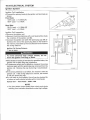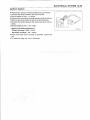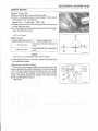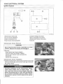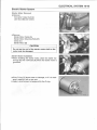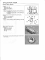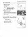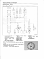
1
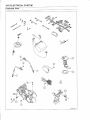
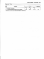
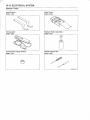
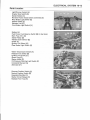
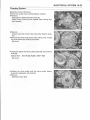
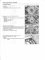
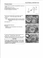
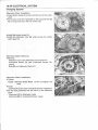
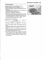
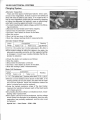
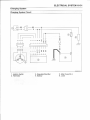
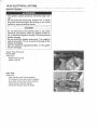
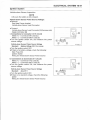
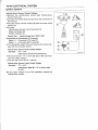
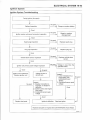
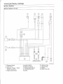
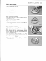
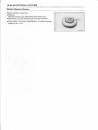
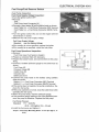
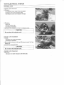
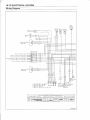
ELECTRICAL SYSTEM 16-1
Electrical System
TABLE OF CONTENTS
Exploded View16- 4
Specifications 16-10
Special Tools 16-12
Parts Location 16-13
Precautions 16-14
Electrical Wiring16-16
Wiring Inspection16-16
Battery
16-17
Battery Removal16-17
Battery Installation16-17
Electrolyte Filling16-17
Initial Charge16-19
Precautions16-19
Interchange16-20
Charging Condition Inspection 16-21
Refreshing Charge16-21
Charging System16-23
Alternator Cover Removal16-23
Alternator Cover Installation 16-24
Alternator Rotor Removal16-25
Alternator Rotor Installation 16-26
Alternator Stator Removal 16-26
Alternator Stator Installation16-26
Regulator/Rectifier Output Voltage
Inspection16-27
Alternator Inspection16-28
Regulator/Rectifier Inspection16-29
Ignition System16-32
Spark Plug Removal16-32
Spark Plug Installation16-33
Spark Plug Cleaning/Inspection ... . 16-33
Spark Plug Gap Inspection 16-33
Ignition Coil Removal16-33
Ignition Coil Installation16-34
Ignition Coil Inspection16-34
Ignition Coil Primary Peak Voltage
Inspection16-36
Crankshaft Sensor Removal16-36
Crankshaft Sensor Installation 16-37
Crankshaft Sensor Inspection16-37
Crankshaft Sensor Peak Voltage
Inspection16-38
Alternator Rotor Inspection 16-38
Ignition Timing Test16-39
Vehicle-down Sensor Outline 16-39
Vehicle-down Sensor Removal16-40
Vehicle-down Sensor Installation .. 16-40
Vehicle-down Sensor Inspection ... 16-41
Electric Starter System 16-45
Starter Motor Removal16-45
Starter Motor Installation16-45
Starter Motor Disassembly16-46
Starter Motor Assembly16-47
Commutator Cleaning/Inspection . . 16-48
Armature Inspection16-49
Starter Motor Brush Length 16-50
Brush Assembly Inspection16-50
Brush Plate and Terminal Bolt
Inspection16-50
Starter Relay Inspection 16-50
Starter Circuit Relay Inspection . . . . 16-51
Starter Motor Clutch Removal 16-52
Starter Motor Clutch Installation .... 16-53
Starter Motor Clutch Inspection .... 16-53
Torque Limiter Inspection 16-54
Lighting System16-55
Headlight Beam Vertical
Adjustment16-55
Headlight Bulb Replacement 16-55
Taillight Bulb Replacement 16-57
Radiator Fan System16-60
Radiator Fan Circuit Inspection16-60
Radiator Fan Motor Inspection 16-60
Fuel Pump/Fuel Reserve Switch 16-61
Fuel Pump Inspection16-61
Fuel Reserve Switch Inspection
(1)
16-62
Fuel Reserve Switch Inspection
(2)
16-62
Indicator Unit 16-64
Indicator Unit Removal16-64
Indicator Unit Installation 16-64
Indicator Unit Inspection 16-64
Switches
16-67
16
16-2 ELECTRICAL SYSTEM
Brake Light Switch Adjustment
Radiator Fan Switch Inspection . . . .
Coolant Temperature Warning
Light Switch Inspection
Switch Inspection
Fuses
16-67
16-67
16-68
16-68
16-70
30 A Main Fuse Removal
Radiator Fan Fuse Removal
Main Fuse Inspection
Radiator Fan Fuse Inspection
Wiring Diagram
16-70
16-70
16-70
16-71
16-72
16-4 ELECTRICAL SYSTEM
Exploded View
ELECTRICAL SYSTEM 16-5
Exploded View
No.
Torque
Fastener
Remarks
N •m
kgf-m
ft-Ib
1
Battery Cable Bolts
5 .9
0 .60
52 in-lb
2
Starter Motor Mounting Bolts
8.8
0 .90
78 in-lb
3
Starter Motor Terminal Nut
4 .9
0 .50
43 in-lb
4
Starter Motor Terminal Locknut
6 .9
0.70
61 in-lb
5
Starter Motor Bolts
4 .9
0 .50
43 in-lb
6
Starter Motor Clutch Bolts
34
3 .5
25
7
Alternator Stator Bolts
13
1 .3
113 in-lb
8
Crankshaft Sensor Mounting Bolts
5 .9
0 .60
52 in-lb
9
Alternator Cover Plugs
18
1 .8
13
10
Alternator Rotor Bolt
127
13
94
11
Alternator Bolt Cover Bolts
8 .8
0 .90
78 in-lb
12
Alternator Cover Bolts
8 .8
0 .90
78 in-lb
G:
L:
M:
0:
R:
Apply grease for oil seal and O-ring .
Apply a non-permanent locking agent .
Apply molybdenum disulfide grease .
Apply engine oil .
Replacement Parts
L
16-6 ELECTRICAL SYSTEM
Exploded View
ELECTRICAL SYSTEM 16-7
Exploded View
No.
Torque
Fastener
Remarks
N-m
kgf-m
ft •I b
1
Spark Plugs
13
1 .3
113 in •l b
2
Ignition Coil Mounting Bolts
5.5
0.55
48 in-lb
3
Igniter Mounting Bolts
2.3
0.23
20 in •I b
4
Oil Pressure Switch
15
1 .5
11
5
Oil Pressure Switch Terminal Bolt
1 .5
0.15
13 in-lb
6
Neutral Position Switch
15
1 .5
11
7
Reverse Position Switch
15
1 .5
11
8
Fuel Pump Mounting Bolts
2.0
0.20
17 in •I b
9
Regulator/Rectifier Bolts
8.8
0.90
78 in-lb
10. Vehicle Down Sensor
G:
L:
S:
SS :
Apply grease for oil seal and O-ring .
Apply a non-permanent locking agent .
Follow the specific tightening sequence .
Apply silicone sealant (Kawasaki Bond : 56019-120) .
SS
16-8 ELECTRICAL SYSTEM
Exploded View
ELECTRICAL SYSTEM 16-9
Exploded View
No.
Fastener
Torque
Remarks
N •m
kgf-m
ft-Ib
1
Radiator Fan Switch
18
1 .8
13
2
Coolant Temperature Warning Light Switch
6.9
0.70
61 in-lb
SS: Apply silicone sealant (Kawasaki Bond : 56019-120) .
SS
16-10 ELECTRICAL SYSTEM
Specifications
Item
Service Limit
Standard
Battery :
Type
Sealed Battery
- - -
Capacity
12 V 12 Ah
- - -
Alternator type
Three-phase AC
- - -
Charging voltage
14 - 15 V
- - -
Alternator output voltage
36 - 54 V 3 000 r/min (rpm)
- - -
Stator coil resistance
0.33 - 0 .49 St
- - -
Spark plug gap
0 .7 - 0.8 mm (0 .028 - 0 .031 in .)
- - -
Spark plug cap resistance
3.75 - 6 .25 kS?
- - -
3 needle arcing distance
7 mm (0 .28 in .) or more
- - -
Primary winding resistance
0.09 - 0 .13 St
- - -
Secondary winding resistance
3.8 - 5 .8 kQ
- - -
Primary peak voltage
50 V or more
- - -
Crankshaft sensor resistance
110 - 140 S2
- - -
Crankshaft sensor peak voltage
1 .8 V or more
- - -
Detection method
Magnetic flux detection method
- - -
Detection angle
More than 65' ± 5` for each bank
- - -
Detection time
Within 0 .5 -- 1 .0 sec .
- - -
Output voltage
in the text
- - -
Charging System :
(Regulator/rectifier output voltage)
Ignition System :
Spark plug :
Ignition coil :
Vehicle-down Sensor
Electric Starter System :
Starter motor :
Commutator diameter
28 mm (1 .10 in .)
27 mm (1 .06 in .)
Brush length
12 mm (0 .47 in .)
4 mm (0 .16 in .)
17.7 - 22 .6 kPa
- - -
Fuel Pump :
Fuel pump pressure
(0 .18 -- 0 .23 kgf/cmz, 2 .6 - 3.3 psi)
Switches :
Brake light switch timing
ON after 10 mm (0.4 in .)
- - -
of pedal travel
Radiator fan switch resistance :
Rising temperature
From OFF to ON at 96 -r
(205 - 212°F)
100°C
- - -
ELECTRICAL SYSTEM 16-11
Specifications
Item
Falling temperature
Standard
From ON to OFF at 91 - 95 C
Service Limit
- - -
(196 -y 203°F)
ON : Less than 0 .5 S2
OFF: More than 1 MS2
Coolant temperature warning light
switch resistance :
Rising temperature
From OFF to ON at 112 - 118°C
(234 - 244"F)
Falling temperature
From ON to OFF at 108 - 111 °C
(226 - 232T)
ON : less than 0.5
s .>
OFF : More than 1 MS2
- - -
16-12 ELECTRICAL SYSTEM
Special Tools
Hook Wrench
57001-1101
Hand Tester
57001-1394
Timing Light
57001-1241
Flywheel Puller Assembly
57001-1405
'ift
Compression Gauge Gasket
57001-1314
Needle Adapter Set
57001-1457
ELECTRICAL SYSTEM 16-13
Parts Location
Light/Dimmer Switch [A]
Engine Stop Switch [B]
Starter Button [C]
Reverse Power Assist Switch (Override) [D]
Rear Brake Light Switch [E]
Ignition Switch [F]
Indicator Unit [G]
Front Brake Light Switch [H]
Battery [A]
Fuel Pump, Fuel Reserve Switch [B] (in fuel tank)
Main Fuse 30 A [C]
Starter Relay [D]
Vehicle Down Sensor [E]
Igniter [F]
Ignition Coil (Rear) [G]
Rear Brake Light Switch [H]
Water Temperature Switch [A]
Radiator Fan Switch [B]
Ignition Coil (Front) [C]
Spark Plug [D]
Starter Motor [E]
Oil Pressure Warning Light Switch [F]
Crankshaft Sensor [G]
Alternator [H]
Reverse Position Switch [A]
Neutral Position Switch [B]
Regulator/Rectifier [C]
Starter Circuit Relays [D]
Radiator Fan Fuse [E]
16-14 ELECTRICAL SYSTEM
Precautions
There are a number of important precautions that should
be taken when servicing electrical systems . Learn and observe all the rules below.
o Do not reverse the battery lead connections . This will
burn out the diodes in the electrical parts .
o Always check battery condition before condemning other
parts of an electrical system . A fully charged battery is
required for conducting accurate electrical system tests .
o The electrical parts should never be struck sharply, as
with a hammer, or allowed to fall on a hard surface . Such
a shock to the parts can damage them .
o To prevent damaging electrical parts, do not disconnect
the battery leads or any other electrical connections when
the ignition switch is on, or while the engine is running .
o Because of the high current, never keep the starter button
depressed when the starter motor will not turn over, or the
current may burn out the starter motor windings .
o Only use an illumination bulb rated for the voltage or
wattage specified in the wiring diagram, or the handle
cover could be warped by excessive heat radiated from
the bulb .
o Take care not to short the leads that are directly connected to the battery positive (+) terminal to chassis
ground .
o Troubles may involve one or in some cases all items .
Never replace a defective part without determining what
CAUSED the failure . If the failure was caused by some
other item or items, they too must be repaired or replaced,
or the new replacement will soon fail again .
o Make sure all connectors in the circuit are clean and tight,
and examine wires for signs of burning, fraying, etc. Defective wires and bad connections will affect electrical system operation .
o Measure coil and winding resistance when the part is cold
(at room temperature) .
o Color Codes:
BK
BL
BR
CH
DG
Black
Blue
Brown
Chocolate
Dark green
G
GY
LB
LG
0
Green
Gray
Light blue
Light green
Orange
P
PU
R
W
Y
Pink
Purple
Red
White
Yellow
ELECTRICAL SYSTEM 16-15
Precautions
O Electrical Connectors :
Female Connectors [A]
Male Connectors [B]
16-16 ELECTRICAL SYSTEM
Electrical Wiring
Wiring Inspection
• Visually inspect the wiring for signs of burning, fraying,
etc.
ArIf any wiring is defective, replace the damaged wiring .
• Pull each connector [A] apart and inspect for corrosion,
dirt, and damage .
*If the connector is corroded or dirty, clean it carefully . If it
is damaged, replace it .
• Check the wiring for continuity.
o Use the wiring diagram to find the ends of the lead which
is suspected of being a problem .
o Connect the hand tester between the ends of the leads .
Special Tool - Hand Tester : 57001-1394
o Set the tester to the x 1 S2 range .
*If the tester does not read 0 S2, the lead is defective . Replace the lead or the wiring harness [B] if necessary .
ELECTRICAL SYSTEM 16-17
Battery
Battery Removal
• Turn off the ignition switch .
• Remove the seat (see Frame chapter)
• Loosen the bolts [A] of the battery holder [B] .
• Remove the battery with the holder and the case .
• Disconnect the battery negative (-) cable [C] first, and
then the positive (+) cable [D] .
• Take out the battery [E] .
Battery Installation
• Turn off the ignition switch .
• Put the battery with the case and the holder in place .
• Connect the positive cable first and then the negative cable .
• Put a light coat of grease on the terminals to prevent corrosion .
• Tighten the battery holder bolts .
Electrolyte Filling
• Make sure that the model name [A] of the electrolyte container matches the model name [B] of the battery . These
names must be the same .
Battery Model Name : KMX 14-BS
CAUTION
Be sure to use the electrolyte container with the
same model name as the battery since the electrolyte volume and specific gravity vary with the
battery type . This is to prevent overfilling of the
electrolyte, shorting the battery life, and deterioration of the battery performance .
• Check to see that there is no peeling, tears or holes in the
seal sheet on the top of the battery .
• Place the battery on a level surface .
• Remove the seal sheet .
CAUTION
Do not remove the aluminum seal sheet [A] sealing
the filler ports [B] until just before use .
NOTE
OA battery whose seal sheet has any peeling, tears,
holes, or from which the air-sucking sound was not
heard requires a refreshing charge (initial charge) .
16-18 ELECTRICAL SYSTEM
Battery
• Take the electrolyte container out of the vinyl bag .
• Detach the seal caps [A] from the container .
o
o
NOTE
Do not discard the seal caps because it is used as the
battery plugs later.
Do not peel back or pierce the seals [B] on the container.
• Place the electrolyte container upside down aligning the
six seals with the six battery filler ports .
• Push the container down strongly enough to break the
seals . Now the electrolyte should start to flow into the
battery .
NOTE
0 Do not tilt the container as the electrolyte flow may be
interrupted.
• Make sure air bubbles [A] are coming up from all six filler
ports .
o Leave the container this way for 5 minutes or longer .
NOTE
o If no air bubbles are coming up from a filler port, tap
[B] the bottom of the bottle two or three times . Never
remove the container from the battery.
CAUTION
Fill the electrolyte into the battery until the container is completely emptied .
• Be certain that all the electrolyte has flowed out .
*Tap the bottom the same way as above if there is any
electrolyte left in the container .
• Now pull the container gently out of the battery .
• Let the battery sit for 20 minutes . During this time, the
electrolyte permeates the special separators and the gas
generated by chemical reaction is released .
ELECTRICAL SYSTEM 16-19
Battery
• Fit the seal caps [A] tightly into the filler ports until the seal
caps are at the same level as the top of the battery .
NOTE
o Do not hammer. Press down evenly with both hands .
CAUTION
Once you installed the seal caps after filling the battery, never remove it, nor add any water or electrolyte .
Initial Charge
While an sealed battery can be used after only filling with electrolyte, a battery may not be able to
sufficiently move a starter motor to start an engine in the cases shown in the table below, where an
initial charge is required before use . However, if a battery shows a terminal voltage of higher than
12 .6 V after 10 minutes of filling (Note 1), no initial charge is necessary.
Condition requiring initial charge
Charging method
At low temperatures (lower than 0`C)
1 .4 A x 2 - 3 hours
Battery has been stored in high temperature and humidity.
Seal has been removed, or broken - peeling, tear or hole .
(If you did not hear the air-sucking sound "Shoosh" as you removed the seal .)
1 .4 A x 15 20
hours
Battery as old as 2 years or more after manufacture .
Battery manufacturing date is printed on battery top.
Example)
12
10
99
T1
Day
Month
Year
Mfg . location
Note 1 : Terminal voltage - To measure battery terminal voltage, use a digital voltmeter .
Precautions
1) No need of topping-up
No topping-up is necessary in this battery until it ends its life under normal use . Forcibly prying
off the sealing_plug to add water is very dangerous . Never do that .
2) Refreshing charge
If an engine will not start, a horn sounds weak, or lamps are dim, it indicates the battery has been
discharged . Give refresh charge for 5 to 10 hours with charge current shown in the specification
(see Refreshing Charge) .
When a fast charge is inevitably required, do it following precisely the maximum charge current
and time conditions indicated on the battery .
1 6-20 ELECTRICAL SYSTEM
Battery
CAUTION
This battery is designed to sustain no unusual deterioration if refresh-charged according
to the method specified above . However, the battery's performance may be reduced noticeably if charged under conditions other than given above .
Never remove the seal caps during refresh charge .
If by chance an excessive amount of gas is generated due to overcharging, the safety valve
operates to keep the battery safe .
3) When you do not use the motorcycle for months
Give a refresh charge before you store the motorcycle and store it with the negative lead removed . Give a refresh charge once a month during storage .
4) Battery life
If the battery will not start the engine even after several refresh charges, the battery has exceeded its useful life . Replace it . (Provided, however, the vehicle's starting system has no problem .)
A WARNING
Keep the battery away from sparks and open flames during charging, since the battery
gives off an explosive gas mixture of hydrogen and oxygen . When using a battery charger,
connect the battery to the charger before turning on the charger . This procedure prevents
sparks at the battery terminals which could ignite any battery gases .
No fire should be drawn near the battery, or no terminals should have the tightening loosened .
The electrolyte contains sulfuric acid . Be careful not to have it touch your skin or eyes . If
touched, wash it off with liberal amount of water. Get medical attention if severe .
Interchange
A sealed battery can fully display its performance only when combined with a proper vehicle electrical system . Therefore, replace a sealed battery only on a vehicle which was originally equipped with
a sealed battery .
Be careful, if a sealed battery is installed on a vehicle which had an ordinary battery as original
equipment, the sealed battery's life will be shortened .
ELECTRICAL
SYSTEM
16-21
Battery
Charging Condition Inspection
Battery charging condition can be checked by measuring
battery terminal voltage .
• Remove the battery (see Battery Removal) .
CAUTION
Be surc '_o c!isconr ect the negative (-) lead first .
• Measure the battery terminal voltage .
NOTE
0 Measure with a digital voltmeter [A] which can be read
to one decimal place voltage .
I a. 0
G7
*If the reading is below the specified, refreshing charge is
required .
Battery Terminal Voltage
Standard :
12.6 V or more
∎∎,.
12 . 0
.,.∎
i
C
• 11 .5
•
12 . 5
•
0 25 50 75 100
Battery Charge(%)
K
:)
IC:>I
Refreshing Charge Good
is required .
GP08010981
Refreshing Charge
• Remove the battery [A] (see Battery Removal) .
• Refresh-charge by following method according to the battery terminal voltage .
A WARNING
This battery is sealed type . Never remove seal
sheet [B] even at charging .
Never add water.
Charge with current and time as stated below .
Terminal Voltage : 11 .5 - less than 12 .5 V
Standard Charge
1 .4 A x 5 - 10 h (see following chart)
Quick Charge
6.0 A x 1 .0 h
CAUTION
If possible, do not quick charge . If the quick charge
is done due to unavoidable circumstances, do the
standard charge later on .
Terminal Voltage : less than 11 .5 V
Charging Method : 1 .4 A x 20 h
0
16-22 ELECTRICAL SYSTEM
Battery
NOTE
o Increase the charging voltage to a maximum voltage of
25 V if the battery will not accept current initially. Charge
for no more than 5 minutes at the increased voltage then
check if the battery is drawing current . If the battery will
accept current [D], decrease the voltage and charge by
the standard charging method described on the battery
case . If the battery will not accept current after 5 minutes, replace the battery.
Battery [A]
Battery Charger [B]
Standard Value [C]
• Determine battery condition after refreshing charge .
o Determine
the condition of the battery 30 minutes after
completion of the charge by measuring the terminal voltage according to the table below .
Criteria
12 .6 V or higher
12 .0 - 12 .5 V or lower
12 .0 V or lower
Judgement
Good
Charge insufficient -> Recharge
Unserviceable - Replace
ELECTRICAL SYSTEM 16-23
Charging System
Alternator Cover Removal
• Drain the coolant (see Cooling System chapter) .
• Remove :
Bolts [A] and Alternator Bolt Cover [B]
Water Pump Cover [C] and Impeller (see Cooling System chapter)
• Remove :
Torque Converter Cover (see Converter System chapter)
• Remove the three bolts of the drive pulley cover, except
for at the dowel pin parts [A] as shown .
[B] Arrow
• Install and tighten the drive pulley holder [A] and the three
bolts [B] .
Special Tool -
Drive Pulley Holder : 57001-1520
[C] Arrow
• Holding the drive pulley with the drive pulley holder,
loosen the alternator rotor bolt [A] .
• Remove :
Alternator Rotor Bolt
16-24 ELECTRICAL SYSTEM
Charging System
• Remove :
Collar [A]
o Install the M6 bolt [B] to the collar, and remove it .
• Place an oil pan under the engine left side .
• Remove:
Alternator and Crankshaft Sensor Lead Connectors (disconnect)
Alternator Cover Bolts [A]
Alternator Cover [B]
Clamp [C]
Alternator Cover Installation
• Be sure all of the old gasket has been removed from the
alternator cover and the left crankcase sealing surfaces .
• Check that the dowel pins [A] are in place, and fit a new
gasket on the crankcase .
• Check that the bearing [B] is in place .
• Fit the grommets [A] into the notch in the cover .
• Grease the alternator cover oil seal .
• Tighten
Torque -Alternator Cover Bolts : 8 .8 N-m (0 .90 kgf-m, 78
in-lb)
ELECTRICAL SYSTEM 16-25
Charging System
• Check that the 0-ring [A] in the collar [B] is in good condition .
• Apply grease to the 0-ring .
• Install the collar on the alternator cover .
• Install the alternator rotor bolt [C] .
HP09008BS1 C
• Hold the drive pulley with the drive pulley holder [A] .
Special Tool - Drive Pulley Holder : 57001-1520
• Tighten :
Torque - Alternator Rotor Bolt : 127 N-m (13 kgf-m, 94 ft-lb)
Alternator Bolt Cover Bolts : 8 .8 N-m (0 .90 kgf-m,
78 in-Ib)
• Add engine oil .
Alternator Rotor Removal
• Remove :
Alternator Cover (see Alternator Cover Removal)
Ball Bearing [A]
• Thread the flywheel puller [A] onto the alternator rotor .
Special Tool - Flywheel Puller : 57001-1405
• Holding the flywheel puller, turn the rotor puller until the
alternator rotor is forced off the end of the crankshaft .
CAUTION
If the rotor is difficult to remove, turn the puller
while tapping the end of the puller. Do not strike
the alternator rotor. Striking the rotor can cause the
magnets to lose magnetism .
16-26 ELECTRICAL SYSTEM
Charging System
Alternator Rotor Installation
• Clean [A] the inside of the rotor and the end of the crankshaft.
• Fit the rotor onto the crankshaft so that woodruff key [B]
fits in the groove [C] in the hub of the rotor.
• Install the torque limiter [A] .
• Install the alternator rotor [B] while turning the starter
clutch gear [C] .
Alternator Stator Removal
• Remove :
Alternator Cover (see Alternator Cover Removal)
Crankshaft Sensor [A] (see Crankshaft Sensor Removal)
Bolts [B] and Alternator Stator [C]
Alternator Stator Installation
• Tighten :
Torque -Alternator Stator Bolts : 13 N-m (1 .3 kgf-m, 113
i n . l b)
• Install :
Crankshaft Sensor (see Crankshaft Sensor Installation)
• Fit the lead grommets into the notch on the alternator
cover.
Grommets [A] for Alternator Leads
Grommets [B] for Crankshaft Sensor Leads
ELECTRICAL SYSTEM 16-27
Charging System
Regulator/Rectifier Output Voltage Inspection
• Remove the seat (see Frame chapter) .
• Check the battery condition (see Battery section) .
• Warm up the engine to obtain actual alternator operating
conditions .
• Check that the ignition switch is turned off, and connect a
hand tester to the battery terminals .
Special Tool - Hand Tester : 57001-1394
• Start the engine and note the voltage readings at various
engine speeds with the headlight turned on and then off .
The readings should show nearly battery voltage when
the engine speed is low, and as the engine speed increases, the readings should also increase .
Regulator/Rectifier Output Voltage
Connections
Reading
Tester Range
25 V DC
Tester (+) to
Tester (-) to
Battery (+)
Battery (-)
14 - 15 V
• Turn off the ignition switch, and disconnect the hand
tester.
*If the regulator/rectifier output voltage is between the values given in the table, the charging system is working normally.
*If the output voltage is much higher than the values specified in the table, the regulator/rectifier is defective or the
regulator/rectifier leads are loose or open .
*If the battery voltage does not increase as the engine
speed increases, then the regulator/rectifier is defective
or the alternator output is insufficient for the loads . Check
the alternator and regulator/rectifier to determine which
part is defective .
16-28 ELECTRICAL SYSTEM
Charging System
Alternator Inspection
There are three types of alternator failures : short, open,
or loss in rotor magnetism . A short or open in one of the coil
wires will result in either a low output, or no output at all . A
loss in rotor magnetism, which may be caused by dropping
or hitting the alternator, by leaving it near an electromagnetic field, or just by aging, will result in low output .
• To check the alternator output voltage, perform the following procedures .
o Remove the rear fender (see Frame chapter) .
o Disconnect the alternator connector [A] .
o Connect a hand tester as shown in the table .
o Start the engine .
o Run it at the rpm given in the table .
o Note the voltage readings (total 3 measurements) .
Alternator Output Voltage
Connections
Tester
Range
Tester (+) to
Tester (-) to
250 V AC
One yellow lead
Another yellow lead
Reading
@3 000rpm
36 - 54 V
*If the output voltage is within the values in the table, the
alternator is operating correctly, and the regulator/rectifier
is damaged . A much lower reading indicates that the alternator is defective .
•
o
o
o
o
Check the stator coil resistance as follows :
Stop the engine .
Disconnect the alternator connector .
Connect a hand tester as shown in the table .
Note the readings (total 3 measurement) .
Stator Coil Resistance
Tester
Ran 9a
x 1 S2
Connections
Tester (+) to
One yellow lead
Tester (-) to
Another yellow lead
Reading
0.33 - 0.49 Q
*If there is more resistance than shown in the table, or no
reading (infinity) for any two leads, the stator has an open
and must be replaced . Much less resistance means the
stator is shorted and must be replaced .
• Using the highest resistance range of the hand tester,
measure the resistance between each of the black leads
and chassis ground .
*Any reading less than infinity (ce) indicates a short, necessitating stator replacement .
*If the stator coils have normal resistance, but the voltage
check shows the alternator to be defective ; then the rotor
magnetism has probably weakened, and the rotor must
be replaced .
Special Tool - Hand Tester : 57001-1394
ELECTRICAL SYSTEM 16-29
Charging System
Regulator/Rectifier Inspection
• Remove :
Connectors [A] (disconnect)
Bolts [B] and Regulator/Rectifier [C]
Rectifier Circuit Check :
• Check conductivity of the following pair of terminals_
Rectifier Circuit Inspection
Tester
connection
W/R-Y1,
W/R-Y2,
W/R-Y3
BK-Y1,
BK-Y2,
BK-Y3
*The resistance should be low in one direction and more
than ten times as much in the other direction . If any two
leads are low or high in both directions, the rectifier is
defective and must be replaced .
NOTE
0 The actual meter reading varies with the meter and the
individual rectifier. Generally speaking the lower reading should be from zero to one half of the scale .
Regulator Circuit Check :
To test the regulator out of circuit, use three 12 V batteries
and a test light (12 V 3 - 6 W bulb in a socket with leads) .
CAUTION
The test light works as an indicator and also a current limiter to protect the regulator/rectifier from excessive current . Do not use an ammeter instead of
a test light .
• Check to be sure the rectifier circuit is correct before continuing .
Regulator Circuit Test-Ist Step :
• Connect the test light and the 12 V battery to the regulator/rectifier as shown .
• Check Y1, Y2, and Y3 terminal respectively .
*If the test light turns on, the regulator/rectifier is defective .
*If the test light does not turn on, continue the test .
16-30 ELECTRICAL SYSTEM
Charging System
Regulator Circuit Test-2nd Step :
• Connect the test light and a 12 V battery in the same manner as specified in the "Regulator Circuit Test-1st Step" .
• Apply 12 V to the BR terminal .
• Check Y1, Y2, and Y3 terminals .
*If the test light turns on, the regulator/rectifier is defective .
*If the test light does not turn on, continue the test .
Regulator Circuit Test-3rd Step :
• Connect the test light and a 12 V battery in the same manner as specified in the "Regulator Circuit Test-1st Step" .
• Momentarily apply 24 V to the BR terminal by adding a 12
V battery.
• Check Y1, Y2, and Y3 terminals .
CAUTION
Do not apply more than 24 V to the regulator/rectifier. Do not leave the 24 V applied for more than a
few seconds, or the unit will be damaged .
*If the test light did not light when the 24 V was applied
momentarily to the BR terminal, the regulator/rectifier is
defective .
*If the regulator/rectifier passes all of the tests described,
it may still be defective . If the charging system still does
not work properly after checking all of the components
and the battery, test the regulator/rectifier by replacing it
with a known good unit .
ELECTRICAL SYSTEM 16-31
Charging System
Charging System Circuit
1 _ Ignition Switch
2. Alternator
3 . Regulator/Rectifier
4 . Battery
5. Main Fuse 30 A
6 . Load
16-32 ELECTRICAL SYSTEM
Ignition System
A WARNING
The ignition system produces extremely high voltage .
Do not touch the spark plug, ignition coil, or spark
plug lead while the engine is running, or you could
receive a severe electrical shock .
CAUTION
Do not disconnect the battery leads or any other
electrical connections when the ignition switch is
on, or while the engine is running . This is to prevent
igniter damage .
Do not install the battery backwards . The negative
side is grounded . This is to prevent damage to the
diodes and igniter.
Use the standard regulator/rectifier, or the igniter
will be damaged .
Spark Plug Removal
Front Side :
• Remove :
Spark Plug Cap [A]
Spark Plug [B]
Rear Side :
• Remove :
Rear Fender (see Frame chapter)
Air Cleaner Cover (see Frame chapter)
Inner Side Cover (see Frame chapter)
Clamp Screws [A] and Clamps
Converter Exhaust Joint Duct [B]
ELECTRICAL SYSTEM 16-33
Ignition System
• Remove :
Spark Plug Cap [A]
Spark Plug [B]
Spark Plug Installation
• Tighten :
Torque -Spark Plugs : 13 N-m (1 .3 kgf-m, 113 in-lb)
• Fit the spark plug caps securely .
• Pull up the spark pug caps lightly to make sure of the
installation of the spark plug caps .
Spark Plug Cleaning/Inspection
• Refer to the Spark Plug Inspection in the Periodic Maintenance chapter .
Spark Plug Gap Inspection
• Refer to the Spark Plug Inspection in the Periodic Maintenance chapter .
Ignition Coil Removal
Front Side :
• Remove :
Spark Plug Cap [A]
Primary Lead Connectors [B]
Bolt [C]
Ignition Coil [D]
Rear Side :
• Remove :
Rear Fender (see Frame chapter)
Air Cleaner Cover (see Frame chapter)
Inner Side Cover (see Frame chapter)
Converter Exhaust Joint Duct (see Spark Plug Removal
(Rear Side))
Spark Plug Cap [A]
Primary Lead Connectors [B]
Bolt [C]
Ignition Coil [D]
16-34 ELECTRICAL SYSTEM
Ignition System
Ignition Coil Installation
• Connect the primary leads to the ignition coil terminals as
shown .
Front Side :
G/W Lead > (+) Mark [A]
BK/Y Lead > (-) Mark
Rear Side :
BL/W Lead > (+) Mark [A]
BK/Y Lead > (-) Mark
Ignition Coil Inspection
• Remove the ignition coil .
• Measure the arcing distance with a coil tester [A] to check
the condition of the ignition coil [B] .
*Connect the ignition coil (with the spark plug cap left attached at the end of the spark plug lead) to the tester in
the manner prescribed by the manufacturer and measure
the arcing distance .
Black
a
C-11
Ignition Coil Arcing Distance
7 mm or more
A WARNING
--~
I
J
Red
To avoid extremely high voltage shocks,
touch the ignition coil body or leads .
o not
If the distance reading is less than the specified value, the
ignition coil or spark plug cap is defective .
• To determine which part is defective, measure the arcing
distance again with the spark plug cap removed from the
ignition coil . Remove the cap by turning it counterclockwise.
*If the arcing distance is as before, the trouble is with the
ignition coil . If the arcing distance is normal, the trouble
is with the spark plug cap .
*If a coil tester is not available, the coil can be checked for
a broken or badly shorted winding with a hand tester.
Special Tool - Hand Tester : 57001-1394
NOTE
o The hand tester cannot detect layer shorts and shorts
resulting from insulation breakdown under high voltage .
14PI0008BS2 C
ELECTRICAL SYSTEM 16-35
Ignition System
•
o
o
•
o
o
Measure the primary winding resistance [A] as follows :
Connect the tester between the coil terminals .
Set the tester to the x 1 Q range .
Measure the secondary winding resistance [B] as follows :
Remove the plug cap by turning it counterclockwise .
Connect the tester between the spark plug lead and terminal .
o Set the tester to the x 1 kQ range .
Ignition Coil Winding Resistance
Primary windings : 0 .09 - 0 .13 1
Secondary windings : 3 .8 -- 5 .8 kQ
*If the hand tester does not read as specified, replace the
coil .
0 To install the plug cap, turn it clockwise .
16-36 ELECTRICAL SYSTEM
Ignition System
Ignition Coil Primary Peak Voltage Inspection
NOTE
o Be sure the battery is fully charged.
• Remove the spark plug cap (see Spark Plug Removal),
but do not remove the spark plug .
• Measure the primary peak voltage as follows .
o Connect a commercially peak voltage adapter [A] to the
hand tester [B] (250 V DC range) . Install the needle
adapters [C] on the peak voltage adapter leads .
Special Tools - Hand Tester : 57001-1394
Needle Adapter Set : 57001-1457
Recommended Tool - Peak Voltage Adapter
Type : KEK-54-9-B
Brand : KOWA SEIKI
o Insert the needle adapter inside the seal of the GIW (front)
or BIJW (rear) lead in the ignition coil [D] until the needle
reaches the terminal in the ignition coil .
o Install a new spark plug [E] into the spark plug cap, and
ground it to the engine .
A WARNING
To avoid extremely high voltage shocks, do not
touch the spark plugs or tester connections .
*Turn the ignition switch ON, rotate the engine for 4 - 5
seconds with the transmission in neutral to measure the
primary peak voltage .
• Repeat the measurements 5 times for one ignition coil .
Ignition Coil Primary Peak Voltage
50 V or more
Standard :
• Repeat the test for the other ignition coil .
*If the reading is less than the specified value, check the
following.
Ignition Coils (see Ignition Coil Inspection)
Crankshaft Sensor (see Crankshaft Sensor Inspection)
*If the ignition coils and crankshaft sensor are normal, see
the Ignition System Troubleshooting chart .
Crankshaft Sensor Removal
• Remove :
Alternator Cover (see Alternator Cover Removal)
Crankshaft Sensor Mounting Bolts [A]
Plate [B]
Crankshaft Sensor [C]
ELECTRICAL
Ignition System
Crankshaft Sensor Installation
• Install :
Stator Coil Leads [A]
Plate [B]
Crankshaft Sensor [C]
• Tighten :
Torque - Crankshaft Sensor Mounting Bolts : 5 .9 N-m (0 .6
kgffm, 52 in •I b)
• Fit the lead grommets into the notch on the alternator
cover.
Grommets [A] for Alternator Leads
Grommets [B] for Crankshaft Sensor Leads
Crankshaft Sensor Inspection
Remove the rear fender (see Frame chapter) .
Disconnect the crankshaft sensor lead connector [A] .
Measure the crankshaft sensor resistance .
Connect a hand tester between the BK/W lead and the
BL lead .
o Set the tester to the x 10 st range .
•
•
•
o
Crankshaft Sensor Resistance
110 - 140 S1
,k if the tester does not read as specified, replace the crankshaft sensor.
SYSTEM
16-37
16-38 ELECTRICAL SYSTEM
Ignition System
Crankshaft Sensor Peak Voltage Inspection
NOTE
o Be sure the battery is fully charged.
• Remove the spark plug caps, but do not remove the spark
plugs .
• Disconnect :
Crankshaft Sensor Wire Connector [A]
• Set the hand tester [B] to the 10 V DC range .
• Connect the peak voltage adapter [C] to the hand tester
and crankshaft sensor leads in the connector .
Special Tool - Hand Tester : 57001-1394
Recommended Tool - Peak Voltage Adapter
Type : KEK-54-9-B
Brand : KOWA SEIKI
Connections :
Crankshaft Sensor Wire
Blue
Black/White
Adapter
-
Red
Black
Hand Tester
(+)
(-)
• Turn the ignition switch on, and rotate the engine for 4 - 5
seconds with the transmission gear in neutral to measure
the pickup coil peak voltage .
• Repeat the measurement 5 or more times .
Crankshaft Sensor Peak Voltage
Standard :
1 .8 V or more
*If the peak voltage is lower than the standard, inspect the
crankshaft sensor .
Alternator Rotor Inspection
• Check the timing projection [A] for damage such as chipping or grooving .
*If the timing projection on the rotor is visibly damaged,
replace the alternator rotor.
ELECTRICAL SYSTEM 16-39
Ignition System
Ignition Timing Test
• Remove the ignition timing inspection plug .
• Attach a timing light [A] and a tachometer in the manner
prescribed by the manufacturer.
Special Tool - Timing Light : 57001-1241
• Start the engine and aim the timing light at the timing mark
on the alternator rotor .
• Run the engine at the speeds specified and note the alignment of the timing marks .
[A] F or R mark
Ignition Timing
Engine speed r/min (rpm)
Slot [B] aligned with :
1 100 and below
Advanced mark [C] on alternator
rotor
5 000 and above
Advanced mark [D] on alternator
rotor
NOTE
o Do not mix up the timing marks with mark [A].
*If the ignition timing is incorrect, replace the igniter and
the crankshaft sensor .
Vehicle-down Sensor Outline
This sensor has a weight [A] with two magnets inside, and
sends a signal to the igniter . But when the vehicle banks 60
- 70' or more to either side (in fact falls down), the weight
turns and shuts off the voltage in the vehicle-down sensor
circuit . The igniter senses this change, and stops the fuel
pump and the ignition system .
Hall IC [B]
16-4 0 ELECTRICAL SYSTEM
Ignition System
Vehicle-down Sensor [A]
Ground Terminal [B] BK/Y
Output Terminal [C] Y/G
Power Source Terminal [D] BR
Constant Voltage Circuit [E]
Hall IC (Integrated Circuit) [F]
Vehicle-down Sensor Circuit [G]
Front [H]
Vehicle-down Sensor Removal
CAUTION
Never drop the down-sensor, especially on a hard
surface . Shock to the sensor can damage it .
• Remove :
Rear Fender (see Frame chapter)
Fuel Tank (see Fuel System chapter)
Vehicle-down Sensor Lead Connector [A]
Screws [B]
Vehicle-down Sensor [C]
Vehicle-down Sensor Installation
• Install the vehicle-down sensor [A] so that the sensor lead
faces backwards [B], and the arrow mark [C] on the sensor points upward .
• Tighten the screws securely .
A WARNING
Incorrect installation of the vehicle-down sensor
could cause sudden loss of engine power. The
rider could lose balance during certain riding situations, like leaning over in a turn, with the potential
for an accident resulting in injury or death . Ensure
that the down sensor is held in place by the sensor
brackets .
ELECTRICAL SYSTEM 16-41
Ignition System
Vehicle-down Sensor Inspection
NOTE
0 Be sure the battery is fully charged .
Vehicle-down Sensor Power Source Voltage :
• Remove :
Seat (see Frame chapter)
Vehicle-down Sensor Lead Connector
• Connect :
Vehicle-down Sensor Lead Connector [A] (harness side)
Digital Volt Meter [B]
I. Connections to Connector (12 V circuit)
Meter (+) -+ Connector BR Lead [C]
Meter (-) > Connector BK/Y Lead [D]
• Turn the ignition switch ON, and measure the power
source voltage .
Vehicle-down Sensor Power Source Voltage
Standard : Battery Voltage (12 .5 V or more)
• Turn the ignition switch OFF .
it If there is no battery voltage, check the following :
Main Fuse 30A
Ignition Switch
Wiring for Vehicle-down Sensor Power Source
II. Connections to Connector (5 V circuit)
Meter (+) > Connector Y/G Lead [E]
Meter (-) > Connector BK/Y Lead [D]
• Turn the ignition switch ON, and measure the power
source voltage .
Vehicle-down Sensor Power Source Voltage
Standard : about 5 V
• Turn the ignition switch OFF.
*If there is no standard voltage, check the following :
Igniter
Wiring for Vehicle-down Sensor Power Source
16-42 ELECTRICAL SYSTEM
Ignition System
Vehicle-down Sensor Output Voltage :
• Remove the vehicle-down sensor (see Vehicle-down
Sensor Removal) .
• Connect the vehicle-down sensor [A] to the connector of
the harness .
• Hold the sensor almost vertical [B] with the arrow mark
pointed up .
• Connect :
Vehicle-down Sensor Lead Connector [C]
Digital Volt Meter [D]
Needle Adapters [E]
Special Tool - Needle Adapter Set : 57001-1457
Connection to Connector (5 V circuit)
Meter (+)
Connector Y/G Lead [F]
Meter (-) Connector BK/Y Lead [G]
• Turn the ignition switch ON, and measure the output voltage with the connector joined .
Vehicle-down Sensor Power Output Voltage
Standard :
0 .4 - 1 .4 V
(with sensor arrow mark pointed up)
• Tilt the sensor 60 - 70° or more [H] right or left, and measure the output voltage .
o The time lag is from 0 .5 to 1 second .
Vehicle-down Sensor Power Output Voltage
Standard : 3 .7 -r 4.4 V
(with sensor tilted 60 - 70 ° or more, right
or left)
*If the output voltage is out of the specified, replace the
vehicle-down sensor.
ELECTRICAL SYSTEM 16-43
Ignition System
Ignition System Troubleshooting
Faulty ignition (No spark)
No good
Battery Inspection
Charge or replace battery
Good
No good
Ignition system wiring and connector inspection
Repair or replace
damaged part
Good
No good
Spark plug inspection
Replace spark plug
No good
Plug cap inspection
Replace plug cap
Good
No good
Vehicle-down sensor inspection
Replace vehicle-down
sensor.
Good
No good
Ignition coil primary peak voltage inspection
v Good
Voltage is less than the
specified value .
No good
Ignition coil is defective .
Replace ignition coil
No good
Voltage is zero or
almost zero .
Inspect
1 . Adapter connection is
incorrect, or adapter is
defective .
2 . Ignition switch and engine
stop switch
3 . Crankshaft sensor peak
voltage .
Inspect
1 . Lower resistance in a
No ood
hand tester (Use
KAWASAKI Hand
Tester)
2 . Crankshaft sensor peak
voltage
Good
Good
Replace bad parts .
Igniter is defective . Rep-lace igniter
F
Replace bad parts or inspect them with KAWASAKI Hand Tester .
1f 100048
F
16-44 ELECTRICAL SYSTEM
Ignition System
Ignition System Circuit
,C7n
,
Ii,
I
OO G
\ m
m
O
m
Y C m
-
Y/G - - Y/G
-BR/R - - BR
-BK/Y -1 BK/Y
BL BK/W -
- BL
-BK/W
3 >
it
J Y
m m
Y
~ m
K 3
m
J\
~~ 3
\\
Y Y\ GG
~ EO C]
>
r 33 T C\\
;
Y ~^ 07 Y J ~
OD 0
3
0
III
1
O
\\\~\\\\\\\\\\\\
~\\\\\\
HP10024BW4 C
1 . Reverse Switch
2. Fuel Pump
3. Reverse Power Assist
Switch (Override)
4. Engine Stop Switch
5. Ignition Switch
6. Reset Connector
7 . Vehicle-down Sensor
8 . Crankshaft Sensor
9 . igniter
10.
11 .
12.
13.
Ignition Coils
Spark Plugs
Battery
Main Fuse 30A
ELECTRICAL SYSTEM 16-45
Electric Starter System
Starter Motor Removal
• Remove :
Converter Intake Duct [A]
Joint Duct [B] and Collars
• Remove :
Starter Motor Cable [A]
Starter Motor Mounting Bolts [B]
Clamp [C]
Starter Motor [D]
CAUTION
Do not tap the end of the starter motor shaft or the
motor may be damaged .
Starter Motor Installation
• When installing the starter motor, clean the starter motor lugs [A] and crankcase [B] where the starter motor is
grounded .
*If the 0-ring [A] shows wear or damage, or if it is hardened, replace it with a new one .
• Apply a small amount of engine oil to the 0-ring .
16-46 ELECTRICAL SYSTEM
Electric Starter System
• Install :
Starter Motor [A]
Clamp [B] (as shown)
Starter Motor Cable [C]
• Tighten :
Torque - Starter Motor Mounting Bolts : 8 .8 N-m (0 .90 kgf-m,
78 in-lb)
Starter Motor Terminal Nut: 4.9 N-m (0 .50 kgf-m,
43 in-lb)
• Apply grease to the O-ring [D] in the joint duct [E] .
• Install :
Joint Duct and Collars [F]
Clamp [G] (as shown)
• Tighten :
Torque -Joint Duct Bolts [H] : 8 .8 N-m (0 .90 kgf-m, 78 in-lb)
Starter Motor Disassembly
• Remove :
Starter Motor Bolts [A]
Left End Cover [B]
Right End Cover [C]
Yoke [D]
• To remove the brush plate assembly [A], remove the terminal nut [B] .
ELECTRICAL SYSTEM 16-47
Electric Starter System
• Hold the brush spring [A] with needle nose pliers, and pull
the brush [B] off the holder.
Starter Motor Assembly
• Replace the O-rings .
• Install the brush plate assembly to the right end cover
so that the projection [A] on the brush plate fits into the
groove on the right end cover .
• Install the O-ring, insulators [B], and washer [C] in that
order on the terminal bolt .
• Tighten :
Torque -Starter Motor Terminal Locknut : 6.9 N-m (0 .70
kgf-m, 61 in-lb)
• Install the washers [A] .
• Install the armature [B] between the brushes .
• Install the yoke [A] onto the right end cover [B] aligning
the marks [C] on the yoke and right end cover .
W11000 ;
P
16-48 ELECTRICAL SYSTEM
Electric Starter System
• Install the plate [A] on the left end cover [B] .
• Align the mark [A] on the left end cover with the mark [B]
on the yoke .
• Tighten :
Torque - Starter Motor Bolts : 4 .9 N •m
(0.50 kgf•m ,
43 in-lb)
Commutator Cleaning/Inspection
• Smooth the commutator surface [A] if necessary with fine
emery cloth [B], and clean out the grooves .
ELECTRICAL SYSTEM 16-49
Electric Starter System
• Measure the diameter [A] of the commutator [B] .
*Replace the starter motor with a new one if the commutator diameter is less than the service limit .
Commutator Diameter
Standard :
28 mm (1 .10 in .)
Service Limit : 27 mm (1 .06 in .)
Armature Inspection
• Using the x 1 c range, measure the resistance between
any two commutator segments [A] .
*If there is a high resistance or no reading (co) between
any two segments, a winding is open . Replace the starter
motor.
• Using the highest range, measure the resistance between
the segments and the shaft [B] .
• If there is any reading at all, the armature has a short .
Replace the starter motor .
Special Tool -
Hand Tester : 57001-1394
NOTE
o Even if the foregoing checks show the armature to be
good, it may be defective in some manner not readily
detectable with the hand tester. If all other starter motor
and starter motor circuit components check good, but
the starter motor still does not turn over or only turns
over weakly, replace the starter motor with a new one .
16-50 ELECTRICAL SYSTEM
Electric Starter System
Starter Motor Brush Length
*Measure the overall length [A] of each brush .
Starter Motor Brush Length
Standard :
12 mm (0 .47 in .)
Service Limit : 4 mm (0 .16 in .)
If any is worn down to the service limit, replace the brush
plate assembly .
Brush Assembly Inspection
• Using the x 1 S2 range, measure the resistance as shown .
[A] Terminal Bolt and Positive Brush
[B] Brush Plate and Negative Brush
*If there is not close to zero ohms, the brush lead has an
open . Replace the brush plate assembly.
Special Tool - Hand Tester : 57001-1394
Brush Plate and Terminal Bolt Inspection
• Using the highest range, measure the resistance as follows :
[A] Terminal Bolt and Right - Hand End Cover
[B] Terminal Bolt and Brush Plate
*If there is any reading, the brush holder assembly has a
short . Replace the brush plate assembly .
Special Tool - Hand Tester : 57001-1394
Starter Relay Inspection
• Remove :
Seat (see Frame chapter)
Starter Relay [A]
ELECTRICAL SYSTEM 16-51
Electric Starter System
• Connect the hand tester [A] and a 12 V battery [B] to the
starter relay [C] as shown .
*If the relay does not work as specified, the relay is defective . Replace the relay .
Testing Relay
Hand Tester Range : x 1 S2 range
Criteria :
When battery is connected' 0 S
When battery is disconnected
= x S2
Special Tool - Hand Tester: 57001-1394
Starter Circuit Relay Inspection
• Remove :
Seat (see Frame chapter)
Rear Fender (see Frame chapter)
Starter Circuit Relays [A] (Brake and Neutral Switch Circuit)
o The starter circuit relays for the brake and neutral switch
circuits are identical .
• Connect the hand tester [A] and a 12 V battery [B] to the
starter circuit relay [C] as shown .
*If the relay does not work as specified, the relay is defective . Replace the relay .
Testing Relay
Hand Tester Range : x I f
Criteria :
When battery is connected = 0 1
When battery is disconnected
Relay Coil Terminals [1] and [2]
Relay Switch Terminals [3] and [4]
= x Q
16-52 ELECTRICAL SYSTEM
Electric Starter System
1.
2.
3.
4.
Engine Stop Switch
Starter Button
Front Brake Light Switch
Brake
Light
Parking
Switch
5 . Rear Brake Light Switch
Circuit
6 . Starter
(Brake)
7 . Ignition Switch
8 . Starter Motor
9 . Starter Relay
10 . Main Fuse 30A
Starter Motor Clutch Removal
• Remove the alternator rotor (see Alternator Rotor Removal) .
• Hold the rotor with the flywheel holder and take out the
starter motor clutch bolts [A] .
Special Tool - Flywheel Holder : 57001-1313
Relay
11 . Battery
12 . Starter
Circuit
(Neutral)
13 . Neutral Switch
Relay
ELECTRICAL SYSTEM 16-53
Electric Starter System
• Take out the one-way clutch [A] .
Starter Motor Clutch Installation
• Install the one-way clutch so that the flange [A] fits on the
recess [B] of the race .
• Apply a non-permanent locking agent :
Starter Motor Clutch Bolts
• Tighten :
Torque - Starter Motor Clutch Bolts : 34 N-m (3 .5 kgf-m, 25
ft-Ib)
Starter Motor Clutch Inspection
• Remove :
Alternator Rotor (see Alternator Rotor Removal)
• Fit the starter clutch gear into the starter motor clutch .
*If the alternator rotor turns counterclockwise [A] freely
from the starter clutch gear, but not clockwise [B], the
clutch is operating correctly .
*If the clutch does not operate correctly, or if it makes
noise, disassemble it and examine each part visually. Replace any worn or damaged parts .
NOTE
o Examine the starter clutch gear [A]. Replace it if it is
worn or damaged.
4P1 :
sD2
16-54 ELECTRICAL SYSTEM
Electric Starter System
Torque Limiter Inspection
• Remove :
Alternator Rotor (see Alternator Rotor Removal)
• Remove the torque limiter [A] and visually inspect it .
*If the limiter has wear, discoloration, or other damage,
replace it as a unit .
ELECTRICAL SYSTEM 16-55
Lighting System
Headlight Beam Vertical Adjustment
• Turn the adjusting screw [A] on each headlight rim in or
out to adjust the headlight vertically.
NOTE
o On high beam, the brightest point should be slightly below horizontal with the vehicle on its wheels and the
rider seated . Adjust both headlights to the same angle .
hP12803E
r
~iP12GC3a
P
Headlight Bulb Replacement
• Remove :
Front Fender (see Frame chapter)
Mounting Screws [A]
Headlight Unit [B]
• Remove:
Headlight Bolts [A] and Washer
Vertical Adjustment Screw [B], Spring, and Nut
Headlight Body [C]
• Remove:
Headlight Connector [A]
Dust Cover [B]
16- 56 ELECTRICAL SYSTEM
Lighting System
• Push the holder [A] and turn it counterclockwise .
• Remove :
Holder
Headlight Bulb [B]
• Insert the new bulb [A] by aligning the projection [B] with
the notch [C] in the headlight unit .
• Push the bulb holder [A] in, turn it clockwise, and release
it . It should lock in position .
• Fit the dust cover [A] .
o Face the TOP mark [B] upward .
ELECTRICAL SYSTEM 16-57
Lighting System
• Install :
Grommet [A]
Vertical Adjustment Screw, Spring and Nut [B]
Damper, Collar and Bolt [C]
Taillight Bulb Replacement
• Remove :
Rear Fender (see Frame chapter)
Tail Light Connector [A]
Screws and Collars [B]
Tail Light Assembly [C] with Cover
• Remove
Screw [A]
Screw and Collar [B]
Tail Light Cover [C]
• Remove the screws [A] .
• Remove the taillight lens [B] from the taillight assembly .
16- 58 ELECTRICAL SYSTEM
Lighting System
• Push the bulb [A] in, turn it counterclockwise, and pull it
out.
• Be sure the socket is clean .
• Insert the new bulb by aligning the pins [A] with the
grooves [B] in the walls of the socket .
• Push the bulb in, turn it clockwise, and release it . It should
lock in position .
ELECTRICAL SYSTEM 16-59
Lighting System
Lighting System Circuit
ar ri
I
I
1?
W J
mm
II
II
II
1'J
m m
~ II I
I1
K J
m m
~II I
1I
K J
m m
K J
m m
I I
I I
d' J
m m
-R/BK - R/Y -BK/Y -
I
I I
- R/BK
- R/Y
- BK/Y-
BR
}
C
Y
m d'
\ m
K
i
O
Y
m
Q, \ J
Y m
m
m m
m
L
3
HI
oOFF
HP120088WC C
1 . Reverse Switch
2 . Reverse Indicator Light
(LED)
3 . Front Brake Light Switch
4 . Parking
Brake
Light
Switch
5 . Rear Brake Light Switch
6 . Headlight (Right)
7 . Headlight (Left)
8 . Reset Connector
9. Light/Dimmer Switch
10 . Ignition Switch
11 . Main Fuse 30A
12 . Battery
13 . Tail/Brake Light
16-60 ELECTRICAL SYSTEM
Radiator Fan System
Radiator Fan Circuit Inspection
• Disconnect the leads from the radiator fan switch [A] .
• Using an auxiliary wire [B], connect the radiator fan switch
leads .
*If the fan rotates, inspect the fan switch .
*If the fan does not rotate, inspect the following .
Leads and Connectors
Main Fuse and Fan Fuse
Fan Motor
Radiator Fan Motor Inspection
• Disconnect the connector [A] in the fan lead .
• Using two auxiliary wires, supply battery [B] voltage to the
fan motor.
*If the fan does not rotate, the fan motor is defective and
must be replaced .
Radiator Fan Motor Leads
BL :
Battery (+)
BK :
Battery (-)
Radiator Fan Circuit
1 . Radiator Fan Fuse 20A
2 . Radiator Fan Switch
3 . Radiator Fan
4 . Main Fuse 30A
5 . Battery
ELECTRICAL SYSTEM 16-61
Fuel Pump/Fuel Reserve Switch
Fuel Pump Inspection
Fuel Pump Supply Voltage Inspection :
• Turn the ignition switch OFF .
• Remove :
Seat
Fuel Pump Lead Connector [A]
• Connect a hand tester [B] with suitable leads as shown .
Hand Tester (+) - Fuel Pump Connector (BR) Terminal
Hand Tester (-) -* Fuel Pump Connector (BK/R) Terminal
• Turn the ignition switch ON, and run the engine with the
transmission in neutral .
• Measure the fuel pump supply voltage .
Fuel Pump Supply Voltage
Standard : near the Battery Voltage
*If the reading is not as specified, replace the igniter .
*If the reading is as specified, check the fuel pump .
Fuel Pump Operational Inspection :
• Remove :
Fuel Pump (see Fuel System chapter)
• Prepare a container filled with kerosene .
• Prepare the rubber hoses, and connect them to the pump
fitting .
• Connect a suitable pressure gauge to the outlet hose as
shown .
Fuel Pump [A]
Pressure Gauge [B]
Outlet Hose [C]
Kerosene [D]
Battery [E] (12V)
*Connect the pump leads to the battery using auxiliary
wires as shown .
Battery (+) - Fuel Pump Connector (BR) Terminal
Battery (-)
Fuel Pump Connector (BK/R) Terminal
*If the pump does not operate, the pump is defective . Replace the fuel pump .
*If the pump operates is normal, close the outlet hose while
operating the fuel pump .
• When the pump stops, read the pressure gauge .
*If the pressure gauge reading is out of the specified pressure, the pump is defective. Replace the fuel pump .
Fuel Pump Pressure
Standard :
17 .7 -- 22 .6 kPa
(0 .18 -- 0 .23 kgf/cm2, 2 .6 - 3 .3 psi)
• Install the fuel pump and tighten it .
Torque - Fuel Pump Mounting Bolts : 2 N-m (0 .2 kgf•m , 17
in-lb)
16-62 ELECTRICAL SYSTEM
Fuel Pump/Fuel Reserve Switch
Fuel Reserve Switch Inspection (1)
• Fill the fuel tank with fuel .
• Close the fuel tank cap surely .
• Remove the fuel tank (see Fuel System chapter) .
• Connect the test light [A] (12 V 3 .4 W bulb a socket with
leads) and the 12 V battery [B] to the fuel pump connector
[C] .
Connections :
Battery (+) > 12 V 3 .4 W Bulb (one side)
12 V 3 .4 W Bulb (other side) > BL Lead Terminal
Battery (-) -> BK/Y Lead Terminal
Special Tool -
Needle Adapter Set: 57001-1457
*If the test light turn on, the reverse switch is defective .
Replace the fuel pump .
Fuel Reserve Switch Inspection (2)
• Remove :
Fuel Pump (see Fuel System chapter)
• Connect the test light (12 V 3 .4 W bulb in a socket with
leads) and the 12 V battery to the fuel pump connector as
shown .
12 V Battery [A]
Test Light [B]
Fuel Pump Connector [C]
Fuel Reserve Switch [D]
*If the test light doesn't light, replace the fuel pump .
NOTE
o It may take a long time to turn on the test light in case
that the fuel reserve switch is inspected just after the
fuel pump is removed . Leave the fuel reserve switch
with leads for inspection connected for 3 minute .
ELECTRICAL SYSTEM 16-63
Fuel Pump/Fuel Reserve Switch
Fuel Pump/Fuel Reserve Switch Circuit
1 . Indicator Unit
2 . Fuel Level Sensor
3. Fuel Pump
4. Igniter
5.
6.
7.
8.
Reset Connector
Main Fuse 30 A
Battery
Ignition Switch
16-6 4 ELECTRICAL SYSTEM
Indicator Unit
Indicator Unit Removal
• Remove :
Air Cleaner Cover (see Frame chapter)
Indicator Unit Lead Connector [A]
Handlebar Cover and Indicator Unit [B]
• Remove :
Bolts [A]
Handle Holders [B]
Handlebar Assembly
• Remove the indicator unit from handlebar cover .
CAUTION
Do not drop the indicator unit .
Indicator Unit Installation
• Install :
Indicator Unit Lead Connector
Handlebar Assembly
o Be sure the indicator unit lead [A] placed under the handlebar [B] .
• Install the removed parts .
CAUTION
Do not drop the indicator unit.
Indicator Unit Inspection
• Remove :
Indicator Unit (see Indicator Unit Removal)
ELECTRICAL SYSTEM 16-65
Indicator Unit
Check1 . Indicator Light Inspection
• Using the auxiliary leads connect a 12 V battery to the
indicator unit connector as follows :
Fuel Indicator Light [A] :
Battery Positive (+) Terminal to Terminal [1]
Battery Positive (-) Negative to Terminal [2]
If indicator light does not go on, replace the indicator unit .
Check2 . LED (light Emitting Diode) Light Inspection
• Using the auxiliary leads, connect a 12 V battery to the
indicator unit connector as follows :
Neutral Indicator Light (LED) [B] :
Battery Positive (+) Terminal to Terminal [1]
Battery Positive (-) Negative to Terminal [3]
Reverse Indicator Light (LED) [C] :
Battery Positive (+) Terminal to Terminal [1]
Battery Positive (-) Negative to Terminal [4]
Water Temperature Warning Light (LED) [D] :
Battery Positive (+) Terminal to Terminal [1]
Battery Positive (-) Negative to Terminal [5]
Oil Pressure Warning Light (LED) [E] :
Battery Positive (+) Terminal to Terminal [1]
Battery Positive (-) Negative to Terminal [6]
Belt Indicator Light (LED) [F] :
Battery Positive (+) Terminal to Terminal [1]
Battery Positive (-) Negative to Terminal [7]
*If each LED light does not go on, replace the indicator
unit .
16-6 6 ELECTRICAL SYSTEM
Indicator Unit
Indicator Unit Circuit
0
0
0
a
E'4100M
C∎MENN∎
BR
BL
-
BR
BL
@J1111
E..J111
I---
m
∎
0
0
HP200358W4 C
1.
2.
3.
4.
Indicator Unit
Neutral Switch
Reverse Switch
Fuel Reserve Switch
5. Igniter
6. Oil Pressure Switch
Temperature
7. Water
Switch
8. Ignition Switch
9. Main Fuse 30A
10. Battery
ELECTRICAL SYSTEM 16-67
Switches
Brake Light Switch Adjustment
• Refer to the Brake Light Switch Inspection in the Periodic
Maintenance chapter.
Radiator Fan Switch Inspection
• Remove:
Radiator Fan Switch (see Cooling System chapter)
• Suspend the fan switch [A] in a container of coolant so that
the temperature sensing projection and threaded portion
are submerged.
• Suspend an accurate thermometer [B] in the coolant .
NOTE
o The switch and thermometer must not touch the container sides or bottom.
• Place the container over a source of heat and gradually raise the temperature of the coolant while stirring the
coolant gently.
• Using the hand tester, measure the internal resistance
of the switch across the terminals at the temperatures
shown in the table .
*If the hand tester does not show the specified values, replace the switch .
Radiator Fan Switch Resistance
ORising temperature :
From OFF to ON at 96 - 100 ° C (205 - 212 ° F)
QFalling temperature :
From ON to OFF at 91 - 95 °C (196 - 203 ° F)
ON : Less than 0 .5 92
OFF : More than 1 MSZ
16- 68 ELECTRICAL SYSTEM
Switches
Coolant Temperature Warning Light Switch Inspection
• Remove :
Coolant Temperature Warning Light Switch (see Cooling
System chapter)
• Suspend the switch [A] in a container of coolant so that
the temperature sensing projection and threaded portion
are submerged .
*Suspend an accurate thermometer [B] in the coolant .
NOTE
o The switch and thermometer must not touch the container sides or bottom .
• Place the container over a source of heat and gradually raise the temperature of the coolant while stirring the
coolant gently.
• Using the hand tester, measure the internal resistance
of the switch across the connector and the body at the
temperatures shown in the table .
~tIf the hand tester does not show the specified values, replace the switch .
Coolant Temperature Warning Light Switch Resistance
QRising temperature :
From OFF to ON at 112 - 118 ° C (234 - 244 ° F)
OFalling temperature :
From ON to OFF at 108 - 111 ° C (226 -- 232 ° F)
ON : Less than 0 .5 SZ
OFF : More than 1 MS1
Switch Inspection
• Using the hand tester, check to see that only the connections shown in the table have continuity (about zero
ohms) .
o For the handlebar switches, ignition switch, refer to tables
in the Wiring Diagram .
*If the switch has an open or short, repair or replace it with
a new one .
ELECTRICAL SYSTEM 16-69
Switches
SW .Terminal
When transmission is in neutral
When transmission is not in neutral
SW.Terminal
When transmission is in reverse
0
When transmission is not in reverse
[B] Reverse Switch
Oil Pressure Switch Connections*
SW. Terminal
When engine is stopped
00
When engine is running
* : Engine lubrication system is in good condition .
16-70 ELECTRICAL SYSTEM
Fuses
30 A Main Fuse Removal
• Remove :
Seat (see Frame chapter)
Starter Relay and 30A Main Fuse Connector [A]
• Pull out the main fuse [B] from the starter relay with a
needle nose pliers .
Radiator Fan Fuse Removal
• Remove :
Seat (see Frame chapter)
Fuse Case Cover [A]
• Pull out the fuse from the fuse case .
Spare Fuse [B]
Main Fuse Inspection
• Inspect the fuse element .
*If it is blown out, replace the fuse . Before replacing a
blown fuse, always check the amperage in the affected
circuit . If the amperage is equal to or greater than the
fuse rating, check the wiring and related components for
a short circuit .
Housing [A]
Fuse Element [B]
Terminals [C]
Blown Element [D]
CAUTION
When replacing a fuse, be sure the new fuse
matches the specified fuse rating for that circuit .
Installation of a fuse with a higher rating may cause
damage to wiring and components .
ELECTRICAL SYSTEM 16-71
Fuses
Radiator Fan Fuse Inspection
• Remove the fuse (see Radiator Fan Fuse Removal) .
• Inspect the fuse element .
*If it is blown out, replace the fuse . Before replacing a
blown fuse, always check the amperage in the affected
circuit . If the amperage is equal to or greater than the
fuse rating, check the wiring and related components for
a short circuit .
Fuse Element [A]
Blown Element [B]
CAUTION
When replacing a fuse, be sure the new fuse
matches the specified fuse rating for that circuit .
Installation of a fuse with a higher rating may cause
damage to wiring and components .
16-72 ELECTRICAL SYSTEM
Wiring Diagram
Frame
Ground
Term ino I
Radiator
Fan Switch V,
Radiator
Fan
IgnIoh Reverse Neutral
Sw itc h
Switch Switch
eL/w
BL
BL
BK
SL
BK/Y
Horn
12V18W
~
BR
-<I-BK/Y
- R/BK
Headlight(Right)
12V45/45W
- BK/Y
Indicator Unit
1
Fuel Indicator Light
12V3 4W
Neutral
Indicator Light(LED)
12V30mW
Reverse
Indicator Light(LED)
Water Temperature
Oil
12V30mW
Warning Light(LED)
12V3OwW
Pressure Warning Light(LED)
12V3OmW
Belt Indicator Light(LED)
12V30mW
w
Headlight(Le
-RISK
- R/Y
12V45/45W
-SK/Y
i
Left Handlebar Switches
1 . Light/Dimmer Switch
2 . Engine Stop Switch
3 . Starter Button
4 . Reverse Power Assist Switch
Alternator
Lcft Handlebar Switch Connections
Light/Dimmer Switch
Color
OFF
LO
R/Y
R
RiB
Enjino St . . Sw .tch
BR
Color
BR
Y/R
Starter Button
Color
R .1Pu h
RRo .e . vane S-0
BK
d
((~~,,
Ce or
BR
Y/BK
OFF
~~OR
011111111111100
W2L0008AW5 C
ELECTRICAL SYSTEM 16-73
Wiring Diagram
Fuel
Reserve
SwItch
K
•
•
-
R
-
/R -
•
K/R
I
r
-
K
Re go I . tori
Rectifire
-fir
aL
BL
I
8K/y
Tail/Brake Light
12V 21/5W
BK/y
R
R
I I I
OPEN
°°
III
4F14
OPEN
Reset
Connector
L__J
Starter
Vehicle-down
Circuit
Relay
(NeutraI)
Sensor
gnition
oils
Spark
4Plugs
Color Code
Starter Motor
lae,t,an
Ceier
S .
teh
OR
C . . . .r,
GY
OFF
ON
e, .
∎
BK
BL
BR
G
Gy
LB
LG
0
P
R
N
Y
Black
Blue
Bro
Green
Gray
L
Kh
i~K"r
B
e
Gc . .e
Orange
n
Rod
e
Yel 0
(58052 . 0008A)
∎2R0000AN5 C
APPENDIX 17-1
Appendix
TABLE OF CONTENTS
Troubleshooting Guide
Cable, Wire, and Hose Routing
17-2
17-6
17
17-2 APPENDIX
Troubleshooting Guide
NOTE
o This is not an exhaustive list, giving every
possible cause for each problem listed . It
is meant simply as a rough guide to assist
the troubleshooting for some of the more
common difficulties.
Engine Doesn't Start, Starting Difficulty :
Starter motor not rotating :
Neutral switch trouble
Starter motor trouble
Battery voltage low
Relays not contacting or operating
Starter button not contacting
Wiring open or shorted
Ignition switch trouble
Engine stop switch trouble
Fuse blown
Starter motor rotating but engine doesn't
turn over :
Starter motor clutch trouble
Engine won't turn over :
Valve seizure
Rocker arm seizure
Cylinder, piston seizure
Crankshaft seizure
Connecting rod small end seizure
Connecting rod big end seizure
Transmission gear or bearing seizure
Camshaft seizure
No fuel flow:
Fuel tank air vent obstructed
Fuel tap clogged
Fuel line clogged
Float valve clogged
Engine flooded :
Fuel level too high
Float valve worn or stuck open
Starting technique faulty
(When flooded, crank the engine with the
throttle
fully opened to allow more air to reach the
engine .)
Fuel/air mixture incorrect :
Pilot screw and/or idle adjusting screw maladjusted
Pilot jet or air passage clogged
Air cleaner clogged, poorly sealed, or missing
Starter jet clogged
No spark ; spark weak :
Spark plug dirty, broken, or maladjusted
Spark plug cap or spark plug lead trouble
Spark plug cap not in good contact
Spark plug incorrect
Crankshaft Sensor trouble
Igniter trouble
Ignition coil trouble
Battery voltage low
Ignition or engine stop switch shorted
Wiring shorted or open
Fuse blown
Compression Low :
Spark plug loose
Cylinder head not sufficiently tightened
down
No valve clearance
Cylinder, piston worn
Piston ring bad (worn, weak, broken, or
sticking)
Piston ring/groove clearance excessive
Cylinder head gasket damaged
Cylinder head warped
Valve spring broken or weak
Valve not seating properly (valve bent,
worn, or carbon accumulation on the
seating surface)
Compression release cam (K.A .C.R.) sticks
open (Engine stalls when moving off)
Poor Running at Low Speed :
Spark weak :
Spark plug dirty, broken, or maladjusted
Spark plug cap or spark plug lead trouble
Spark plug cap shorted or not in good contact
Spark plug incorrect
Igniter trouble
Pickup coil trouble
Ignition coil trouble
Battery voltage low
Fuel/air mixture incorrect :
Pilot screw and/or idle adjusting screw maladjusted
Pilot jet or air passage clogged
Starter plunger stuck open
Air cleaner clogged, poorly sealed, or missing
Fuel level too high or too low
Fuel tank air vent obstructed
Carburetor holder loose
Air cleaner duct loose
Compression low :
Spark plug loose
Cylinder head not sufficiently tightened
down
No valve clearance
APPENDIX 17-3
Troubleshooting Guide
Cylinder, piston worn
Piston ring bad (worn, weak, broken, or
sticking)
Piston ring/groove clearance excessive
Cylinder head gasket damaged
Cylinder head warped
Valve spring broken or weak
Valve not seating properly (valve bent,
worn, or carbon accumulation on the
seating surface)
Compression release cam (K.A .C.R.) sticks
open (Engine stalls when moving off)
Other:
Carburetor vacuum piston doesn't slide
smoothly
Engine oil viscosity too high
Brake dragging
Igniter trouble
Final gear case oil viscosity too high
Poor Running or No Power at High Speed :
Firing incorrect :
Spark plug dirty, broken, or maladjusted
Spark plug cap or spark plug lead trouble
Spark plug cap shorted or not in good contact
Spark plug incorrect
Pickup coil trouble
Igniter trouble
Ignition coil trouble
Fuel/air mixture incorrect :
Main jet clogged or wrong size
Jet needle or needle jet worn
Main air jet clogged
Bleed holes of air bleed pipe or needle jet
clogged
Fuel level too high or too low
Air cleaner clogged, poorly sealed, or missing
Starter plunger stuck open
Water or foreign matter in fuel
Carburetor holder loose
Air cleaner duct loose
Fuel tank air vent obstructed
Fuel tap clogged
Fuel line clogged
Compression low :
Spark plug loose
Cylinder head not sufficiently tightened
down
No valve clearance
Cylinder, piston worn
Piston rings bad (worn, weak, broken, or
sticking)
Piston ring/groove clearance excessive
Cylinder head gasket damaged
Cylinder head warped
Valve spring broken or weak
Valve not seating properly (valve bent,
worn, or carbon accumulation on the
seating surface .)
Compression release cam (K.A .C.R.) sticks
open (Engine stalls when moving off)
Knocking :
Carbon built up in combustion chamber
Fuel poor quality or incorrect
Spark plug incorrect
Igniter trouble
Miscellaneous :
Throttle valve won't fully open
Carburetor vacuum piston doesn't slide
smoothly
Brake dragging
Overheating
Engine oil level too high
Engine oil viscosity too high
Final gear case oil viscosity too high
Overheating :
Firing incorrect :
Spark plug dirty, broken, or maladjusted
Spark plug incorrect
Igniter trouble
Fuel/air mixture incorrect :
Main jet clogged
Fuel level too low
Carburetor holder loose
Air cleaner poorly sealed, or missing
Air cleaner duct loose
Air cleaner clogged
Compression high :
Carbon built up in combustion chamber
Compression release cam (K.A .C.R.) sticks
close
Engine load faulty :
Engine oil level too high
Engine oil viscosity too high
Drive train trouble
Brake dragging
Lubrication inadequate :
Engine oil level too low
Engine oil poor quality or incorrect
Final gear case overheating :
Insufficient oil
Bevel gears maladjusted
Coolant incorrect:
Coolant level too low
Coolant deteriorated
17-4 APPENDIX
Troubleshooting Guide
Thick coolant
Cooling system component incorrect :
Radiator clogged
Thermostat trouble
Radiator cap trouble
Radiator fan switch trouble
Fan motor broken
Fan blade damaged
Water pump not turning
Water pump impeller damaged
Over Cooling :
Cooling system component incorrect :
Radiator fan switch trouble
Thermostat trouble
Converter Operation Faulty :
Belt slipping :
Belt dirty, worn, or wetted
Drive or driven pulley sheave dirty or worn
Drive pulley spring broken or weak
Converter engagement speed too low :
Drive pulley spring broken or weak
Converter engagement speed too high :
Belt dirty or worn
Drive or driven pulley sheave dirty or worn
Drive pulley weight doesn't move smoothly
Drive pulley movable sheave doesn't move
smoothly
Drive or driven pulley movable sheave bush
worn
Drive pulley weight or roller worn
Shifting too quickly :
Drive pulley spring weak
Driven pulley spring weak or incorrectly installed (too loose)
Shifting too slowly :
Belt dirty or worn
Drive or driven pulley sheave dirty or worn
Drive pulley weight doesn't move smoothly
Drive pulley movable sheave doesn't move
smoothly
Drive pulley spring incorrect installed (too
tight)
Driven pulley movable sheave doesn't
move smoothly
Gear Shifting Faulty :
Doesn't go into gear :
Shift shaft bent or seized
Gear stuck on the shaft
Shift control grip damaged
Shift control cable maladjusted
Reverse lock maladjusted
Jumps out of gear :
Shifter groove worn
Gear dogs worn
Shift block worn
Shift fork worn
Shift shaft spring weak or broken
Shift control cable maladjusted
Drive shaft, output shaft, and/or gear
splines worn
Overshifts :
Shift shaft spring weak or broken
Shift control cable maladjusted
Abnormal Engine Noise :
Knocking :
Igniter trouble
Carbon built up in combustion chamber
Fuel poor quality or incorrect
Spark plug incorrect
Overheating
Piston Slap :
Cylinder/piston clearance excessive
Cylinder, piston worn
Connecting rod bent
Piston pin, piston holes worn
Valve noise :
Valve clearance incorrect
Valve spring broken or weak
Camshaft bearing worn
Rocker arm worn
Other noise :
Connecting rod small end clearance excessive
Connecting rod big end clearance excessive
Piston ring worn, broken, or stuck
Piston seizure, damage
Cylinder head gasket leaking
Exhaust pipe leaking at cylinder head connection
Crankshaft runout excessive
Engine mounts loose
Crankshaft bearing worn
Camshaft chain tensioner trouble
Camshaft chain, sprocket, guides worn
Loose alternator rotor
Abnormal Drive Train Noise :
Converter noise :
Belt worn
Drive or driven pulley sheave worn
Drive or driven pulley movable sheave bush
worn
Drive or driven pulley mount loose
Driven pulley shoe worn
Drive pulley weight or roller side washer
worn
APPENDIX 17-5
Troubleshooting Guide
Drive pulley weight or roller worn
Wear guides worn
Transmission noise :
Bearing worn
Transmission gears worn or chipped
Metal chips jammed in gear teeth
Engine oil insufficient or too thin
Final gear case noise :
Insufficient lubricant
Bevel gear bearings worn
Bevel gears worn or chipped
Bevel gears maladjusted
Abnormal Frame Noise :
Shock absorber noise :
Shock absorber damaged
Disc brake noise :
Pad installed incorrectly
Pad surface glazed
Disc warped
Caliper trouble
Rear brake noise :
Foreign matter in hub
Brake not properly adjusted
Other noise:
Bracket, nut, bolt, etc .
not properly
mounted or tightened
Exhaust Smokes Excessively :
White smoke :
Piston oil ring worn
Cylinder worn
Valve oil seal damaged
Valve guide worn
Cylinder head gasket damaged
Engine oil level too high
Black Smoke :
Air cleaner clogged
Main jet too large or fallen off
Starter plunger stuck open
Fuel level too high
Brown smoke :
Main jet too small
Fuel level too low
Air cleaner duct loose
Air cleaner poorly sealed or missing
Handling and/or Stability Unsatisfactory
Handlebar hard to turn :
Tire air pressure too low
Steering stem bearing damaged
Steering stem bearing lubrication inadequate
Steering stem bent
Damage tie-rod end
Handlebar shakes or excessively vibrates :
Tire worn
Wheel rim warped
Rear axle runout excessive
Wheel bearing worn
Handlebar clamp loose
Steering stem clamp bolt loose
Handlebar pulls to one side :
Frame bent
Wheel maladjustment
Suspension arm bent or twisted
Steering stem bent
Front or rear tire air pressure unbalanced
Front shock absorber unbalanced
Shock absorption unsatisfactory :
Too hard :
Tire air pressure too high
Shock absorber maladjusted
Too soft :
Shock absorber oil leaking
Shock absorber spring weak
Tire air pressure too low
Shock absorber maladjusted
Brake Doesn't Hold
Front brake :
Air in the brake line
Brake fluid leakage
Brake fluid deteriorated
Primary or secondary cup trouble
Master cylinder scratched inside
Pad overworn or worn unevenly
Oil, grease on pads and disc
Disc worn or warped
Brake overheated
Rear Brake :
Brake not properly adjusted
Plates worn
Brake parts worn or damaged
Battery Discharged :
Battery faulty (e .g ., plates sulphated,
shorted through sedimentation, electrolyte level too low)
Battery leads making poor contact
Load excessive (e .g ., bulb of excessive
wattage)
Ignition switch trouble
Regulator/rectifier trouble
Alternator trouble
Wiring faulty
Battery Overcharged :
Regulator/rectifier trouble
Battery trouble
17-6 APPENDIX
Cable, Wire, and Hose Routing
1 . Tube
2 . Clamp
3 . Align the white paint mark on the tube with the adjustment mark on the crankcase .
4. Electric Starter
APPENDIX 17-7
Cable, Wire, and Hose Routing
1.
2.
3.
4.
5.
6.
Cooling Hoses
Clamps (Install the clamps with the tabs direction as shown .)
Coolant Valve
Position the white marks on the tube as shown .
Damper
Clamps
17-8 APPENDIX
Cable, Wire, and Hose Routing
1 . Clamp
2. Engine Ground Lead
3. Install the clamp on the engine ground lead .
APPENDIX 17-9
Cable, Wire, and Hose Routing
1 . Water Pipe
2 . White Paint
3 . Clamps
4 . Cooling Hoses
5 . Coolant Filter Body
6. Coolant Filter
7 . Carburetor
8 . Mark
9 . Cooling Hose
10 . Assemble Angle (about 45`, [4] and [9]
hoses)
11 . Cooling Hose
17-10 APPENDIX
Cable, Wire, and Hose Routing
1.
2.
3.
4.
5.
6.
7.
White Paint
Water Pipe
Clamp
Cooling Hose
To Carburetor
Carburetor Overflow Tube
Exhaust Pipe Cover
8.
9.
10.
11 .
12.
13.
14.
Tube
Breather
Pump Cover
Mark
To Radiator
Duct
Face the clamp screw as shown .
APPENDIX 17-11
Cable, Wire, and Hose Routing
1.
2.
3.
4.
5.
6.
7.
Air Cleaner Duct
Clamps
Clamps
Boots
Clamp
Vent Hose
To Crankcase
8.
9.
10 .
11 .
12 .
13 .
Coolant Valve
Coolant Tube
Starter Cable
Carburetor
Clamps
Air Vent Tube
17-12 APPENDIX
Cable, Wire, and Hose Routing
1.
2.
3.
4.
5.
6.
Clamps
Bands
Ignition Coil (Rear)
Clamp
Clamp
Clamp
7 . Drain Plug
8 . Drain Hose
9 . Vent Hose
10 . Align the mark .
11 . Fit the projection and groove of the each
ducts .
APPENDIX 17-13
Cable, Wire, and Hose Routing
1 . Coolant Temperature Warning
Switch
2. Reserve Tank
3. Reserve Tank Breather Hose
4. Cooling Hose
5 . Clamp
6 . Radiator Hose
Light
7 . Radiator
8. Forward
9 . Face the reserve tank breather hose as
shown .
10. Fan Motor Breather Hose
11 . Fan Motor Lead
17-14 APPENDIX
Cable, Wire, and Hose Routing
1.
2.
3.
4.
5.
6.
7.
Radiator Hose
Cooling Hose
Reserve Tank
Radiator Fan Switch
Fan Motor Lead
Fan Motor Breather Hose
Clamp
8.
9.
10.
11 .
12.
13.
Clamp
Face the white paint upward .
To Thermostat
To Water Pump
To Fan Motor
To Final Gear Case
APPENDIX 17-15
Cable, Wire, and Hose Routing
1 . Fuel Tap
2. Fuel Tap Vacuum Hose
3. Clamp
4. Fuel Hose
5. Fuel Filter
6. To Fuel Tank
7. Face the clamp as shown .
17-16 APPENDIX
Cable, Wire, and Hose Routing
1.
2.
3.
4.
5.
6.
Front Brake Switch Lead
Throttle Cable
Front Brake Hose
Indicator Unit Lead
Ignition Switch Lead
Brake Switch Lead
7.
8.
9.
10 .
11 .
Left Handlebar Switch Lead
Parking Brake Cable
Choke Cable
Shift Control Cable
Shift Control Cable
APPENDIX 17-17
Cable, Wire, and Hose Routing
1.
2.
3.
4.
5.
6.
Throttle Cable
Choke Cable
Shift Control Cable
Clamp the choke cable only with the band .
Band
To Front Side of Shift Control Grip
17-18 APPENDIX
Cable, Wire, and Hose Routing
1.
2.
3.
4.
5.
6.
Final Gear Case Breather Hose
Band
Reverse Lock Cable
Clamp
Rear Brake Cable
Parking Brake Cable
7. Clamp
8. Band (With the Rear Brake Light Switch)
9 . Through the parking brake cable upper
side on the cross pipe .
10. Shift Control Cable
11 . To Rear Side of Shift Control Grip
APPENDIX 17-19
Cable, Wire, and Hose Routing
1.
2.
3.
4.
5.
6.
7.
8.
9.
10 .
Head Light Lead
Horn Connector
Clamp
Clamp
Convertor Duct
Indicator Unit Lead Connector
Rear Brake Switch Lead Connector
Front Brake Switch Lead Connector
Ignition Switch Lead Connector
Left Handlebar Switch Lead Connector
11 . Reverse Power Assist Switch Lead Connector
12 . Clamp
13. Clamp
14. Radiator Fan Connector
15. Ground (Tighten with the thermostat
cover bolt .)
16. Water Temperature Warning Switch Lead
17. Radiator Fan Switch Lead
17-20 APPENDIX
Cable, Wire, and Hose Routing
1 . Left Head Light Lead Connector
2 . Radiator Fan Connector
3 . Radiator Fan Switch Connector
4 . Water Temperature Warning Switch Lead
5 . Ground (Tighten with the thermostat
cover bolt .)
6. Clamp
7.
8.
9.
10 .
11 .
12.
13.
Ignition Coil (Front)
Clamp
Band
Regulator/Rectifier
Clamp
Starter Circuit Relays
Clamp
APPENDIX 17-21
Cable, Wire, and Hose Routing
1 . To Engine Ground
2 . Main Harness
3 . Clamp (Main Harness Accessory)
4 . Fuel Tank Breather Hose
5 . To Tail/Brake Light
6. Vehicle-down Sensor
7. Starter Relay/Main Fuse
8.
9.
10 .
11 .
12.
13.
To Regulator/Rectifier
To Reverse/Neutral Switch
Battery
Fuse Case (For Radiator Fan)
Spare Fuse
Reset Connectors
17-22 APPENDIX
Cable, Wire, and Hose Routing
1 . To Tail/Brake Light
2. Clamp
3. Run the main harness under the seat
bracket .
4 . Clamp (With the Fuel Hose)
5. Igniter
6. Ignition Coil (Rear)
7. Band (Face the end of the band upward .)
8 . Clamp
9 . Clamp
10 . Clamp
11 . To Right Headlight
12 . Rear Brake Light Switch
13 . Band (With the Final Gear Case Breather
Hose)
APPENDIX 17-23
Cable, Wire, and Hose Routing
1.
2.
3.
4.
Clamp
Clamp
Fuel Tank Breather Hose
Fuel Hose
5. Clamp the fuel hose and main harness .
6 . Through the hoses above the main harness .
7 . Clamp
17-24 APPENDIX
Cable, Wire, and Hose Routing
1 . Through the brake hose to the clamp . (Left Side Only)
2. Through the brake hose to the clamp on the left side suspension arm .
3. Fit the grommet to the frame clamp .