1
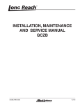
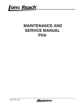
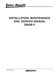
Installation, Maintenance and
Service Manual
TNNA
Integral Carriages
45-082, REV. 8/14
1 of 7
1
TABLE OF CONTENTS
SECTION 1 NAMEPLATE LOCATION................ 3
2.11 Maintenance Warnings.............................6
SECTION 2 SAFETY SUMMARY....................... 4
2.12 Load Handling..........................................7
2.1 Safety Information......................................4
2.13 Load Positioning.......................................7
2.2 Safety Regulations.....................................4
2.14 Operator’s Controls ..................................7
2.3 Safety Symbols...........................................4
2.15 Industry Standards...................................8
2.4 Labeling......................................................4
2.16 Clamp Open Control.................................8
2.5 Training.......................................................4
SECTION 3 MAINTENANCE............................ 10
2.6 Personnel Safety........................................5
3.1 Schedule...................................................10
2.7 Pre-start Checks.........................................5
Daily:..........................................................10
2.8 Operation Warnings....................................5
40 Hour Maintenance:................................10
2.9 Hydraulic Hazards .....................................6
100 Hour Maintenance:..............................10
2.10 Electrical Hazards.....................................6
3.2 Torque Specifications................................10
2
45-082, REV. 8/14
SECTION 1 NAMEPLATE LOCATION
NOTICE
When you receive your attachment,
locate the Long Reach nameplate (upper
left corner on the body). Record the
information from the nameplate, along
with the date received, at the bottom of
this page. If the nameplate is missing, look
for the serial number stamped directly into
the metal at the nameplate location and
consult the factory for details.
APPROX.
S/N PLATE
LOCATION
Date Received:
-
45-082, REV. 8/14
-
3 of 7
3
SECTION 2 SAFETY SUMMARY
CAUTION
3.1 Safety Information
Safety is Everyone’s Responsibility
Whether you are new on the job or a seasoned veteran,
these safety tips may prevent injury to you, to others, or
to the materials you are handling. Always be alert, watch
out for others, and follow these suggestions:
Attachments handle material, not people.
Safety starts with common sense, good
judgement, properly maintained equipment,
careful operation, and properly trained
operators.
The safety instructions and warnings, as documented
in this manual and shipped with the machine, provide
the most reliable procedures for the safe operation and
maintenance of your Long Reach attachment. It’s your
responsibility to see that they are carried out.
Indicates a hazardous situation which,
if not avoided, could result in minor or
moderate injury, or equipment damage or
void the machine warranty. Carefully read
the message that follows to prevent minor
or moderate injury.
NOTICE
Describes information that is useful but not
safety related.
WARNING
3.2 Safety Regulations
Multiple hazards.
Know your company’s safety rules. Some companies
have site-specific directions and procedures. The methods outlined in your operator’s manual provide a basis for
safe operation of the machine. Because of special conditions, your company’s material handling procedures may
be somewhat different from those shown in this manual.
Ignoring safety warnings may cause
equipment damage, personal injury or
death.
3.3 Safety Symbols
The following terms define the various precautions and
notices:
DANGER
Indicates a hazardous situation which, if
not avoided, will result in death or serious
injury. Carefully read the message that
follows to prevent serious injury or death.
WARNING
Indicates a hazardous situation which,
if not avoided, could result in death or
serious injury. Carefully read the message
that follows to prevent serious injury or
death.
4
All possible safety hazards cannot be
foreseen and included in this manual. The
operator must always be alert to possible
hazards that could endanger personnel or
damage the equipment.
3.4 Labeling
• Change capacity, operation, and maintenance instruction plates, tags, or decals when a forklift truck is
equipped with an attachment. If the truck is equipped
with front-end attachments other than factory installed
attachments, truck must be marked to identify the
attachments and show the approximate weight of
the truck and attachment combination at maximum
elevation with load laterally centered.
3.5 Training
• Make sure all operators are trained in the fork and
attachment adaptation, operation, and use limitations.
Retrain an operator if a new attachment is added to
the forklift. Consult the operator’s manual for instructions on how to use the new equipment.
• Know the mechanical limitations of your forklift.
45-082, REV. 8/14
• Modifications or additions that affect capacity or safe
operation must have prior written approval from the
forklift truck manufacturer. Capacity, operation, and
maintenance instruction plates, tags, or decals shall
be changed accordingly.
• Never use free rigging for a below-the-forks lift. It could
affect the capacity and safe operation of a lift truck.
3.6 Personnel Safety
• Never allow anyone under a load or under the carriage. (Figure 3-2)
• Never stand in front of or beside an attachment that
is being operated. Never allow another person to approach an attachment that is being operated. (Figure
3-3)
• Never leave an attachment or load in an elevated
position.
• When removing or installing dismountable attachments always keep hands and feet free from
dangerous positions or pinch points. Never leave a
dismounted attachment in a dangerous position.
• Never reach through the mast of the truck. Keep all
parts of the body within the driver’s compartment.
• Keep hands, feet, long hair and clothing away from
power-driven parts. Do not wear loose fitting clothing
or jewelry while performing maintenance and lubrication in these areas.
• Do not allow riders on the truck at any time.
• Never jump on or off the machine.
• Always use personal protective equipment (PPE)
appropriate to the situation.
• Never stand on top of material being raised, lowered,
or transported. (Figure 3-1)
• Always operate an attachment from the operator’s
seat, never while standing next to the lift truck.
• Always use reverse when carrying a load that impedes
full vision. Watch for pedestrians when transporting.
3.7 Pre-start Checks
• Check your equipment before you operate it. If anything looks wrong, unusual or different, report it before
using the attachment.
• Do not operate this machine if you know of malfunctions, missing parts, and/or mis-adjustments. These
situations can cause or contribute to an accident or
damage to the machine. Stop the machine immediately if problems arise after starting.
• Check to make sure the attachment on your truck is
the same as on the truck capacity plate.
Figure 3-1
• Check for hydraulic leaks and cracked hoses or fittings. Check the hydraulic oil level in the lift truck
hydraulic reservoir.
• All electrical cables and connectors must be in good
condition. Use caution in wet weather to avoid danger
from electrical shock.
Figure 3-2
• Always check the attachment for proper fit and engagement of the truck carriage.
3.8 Operation Warnings
• You must be trained to operate this equipment prior to
operation. Be extremely careful if you do not normally
operate this machine. Reorient yourself to the machine
before starting, then proceed slowly.
Figure 3-3
• Always operate an attachment from the driver’s seat.
• Never use the attachment or its load to support a
man-carrying device.
45-082, REV. 8/14
5 of 7
• Always lower the attachment if you need to leave the
lift truck. A lift truck supporting a load requires your
full attention.
5
3.9 Hydraulic Hazards
DANGER
Injection hazard.
Infection and gangrene will result
when hydraulic oil penetrates the
skin. See a doctor immediately to
prevent loss of limb or death.
Use a piece of cardboard to check for
hydraulic leaks.
• Wear personal protective equipment, such as gloves
and safety glasses, whenever servicing or checking
a hydraulic system.
• Assume that all hydraulic hoses and components are
pressurized. Relieve all hydraulic pressure before
disconnecting any hydraulic line.
• Never try to stop or check for a hydraulic leak with any
part of your body; use a piece of cardboard to check
for hydraulic leaks.
3.10 Electrical Hazards
WARNING
Electrocution hazard.
Contact with energized equipment may
result in injury or death and will damage
equipment.
Remain at least 25 feet from high voltage
electrical wires.
• All electrical cables and connectors must be in good
condition (free of corrosion, damage, etc). Use caution in wet weather to avoid danger from electrical
shock. Never attempt electrical testing or repair while
standing in water.
• Do not wear electrically conductive jewelry, clothing,
or other items while working on the electrical system.
3.11 Maintenance Warnings
Maintenance, lubrication and repair of this machine can
be dangerous unless performed properly. You must have
the necessary skills and information, proper tools and
equipment. Work in a method that is safe, correct, and
meets your company’s requirements.
6
• Do not attempt to make adjustments, or perform
maintenance or service unless you are authorized
and qualified to do so.
• Include attachments in a scheduled maintenance
and inspection program. Tailor inspection steps to
the attachment.
• Unless specified in service procedures, never attempt
maintenance or lubrication procedures while the machine is moving or the engine is running.
• Always perform all maintenance and lubrication procedures with the machine on level ground, parked
away from traffic lanes.
NOTICE
Local laws and regulations may require
that additional safety measures be taken.
• Never rely on the hydraulic system to support any
part of the machine during maintenance or lubrication.
Never stand under a component that is supported
only by the hydraulics. Make sure it is resting on its
mechanical stops or appropriate safety stands.
• Use caution when working around hot fluids. Always
allow lubricating and hydraulic oils to cool before
draining. Burns can be severe.
• Use extreme caution when using compressed air to
blow parts dry. The pressure should not exceed 30
psi (208 kPa) at the nozzle. Never use compressed
air on yourself. Air pressure penetrating your skin
can be fatal.
WARNING
Suffocation hazard.
Engine exhaust fumes can cause death.
Remove the exhaust fumes from the area
with an exhaust pipe extension, or use
ventilation fans and open shop doors to
provide adequate ventilation.
• Before disconnecting hydraulic lines, be sure to lower
all loads and relieve all hydraulic pressure. The load
could fall on you, or escaping hydraulic oil could cause
severe personal injury.
• Prevent personal injury or equipment damage by using a lifting device with a lifting capacity greater than
twice the weight of any equipment to be lifted.
45-082, REV. 8/14
3.12 Load Handling
3.13 Load Positioning
• Treat an unloaded forklift with an attachment as partially loaded.
• Be accurate in load placement. It’s important to know
what the load will do when it’s released.
Equipment overload hazard.
Injury or equipment damage may result if
the capacity of the truck and attachment
combined are less than the attachment
capacity.
Consult truck nameplate for truck
capacity with an attachment installed.
• Always carry loads as close to the floor as possible,
consistent with the surface being traversed. Scraping
or bumping the floor surface with the load or the attachment can severely damage the attachment and
cause product damage. The mast should be tilted
back.
• Always keep the load positioned as close as possible
to the horizontal center of the lift truck.
• Always back down ramps or inclines. Driving forward
down a ramp or incline with a clamped load will lessen
the stability of the truck. (Figure 3-4)
• Never overload the attachment. Refer to the attachment nameplate for the rated capacity of the attachment. Refer to the truck nameplate for the maximum
net working capacity of the truck/attachment combination. Never use a load to support or move another
object. Doing so can easily exceed the holding capacity of the attachment.
• Always check loads to be handled. Correct loads that
are broken, unbalanced, loose, or too heavy.
• Never lift, lower, side shift, pivot, rotate, or tilt loads
while traveling. Repositioning loads while traveling affects the stability of the truck and may impede vision
or clearances.
• Do not use an attachment to open or close boxcar
doors. Doing so can severely damage the attachment
and cause loss of warranty. Damage to clamp arms
may result in product damage.
• Do not carry loose items or unsupported loads on top
of a clamped load.
• Never use chains, cables, or other devices in conjunction with an attachment for load handling.
• Never clamp loads other than what the attachment
was designed to handle.
• Always carry cylindrically shaped loads in the vertical
position, not the horizontal.
• Always clamp loads with the contact pads, if applicable, not the arm or arm base.
• Never rotate a load that is off center to the centerline
of rotation. Severe damage to the rotator could result.
• Always ensure that the load is the same width as the
pallet and neatly stacked when using a carton clamp.
45-082, REV. 8/14
7 of 7
Figure 3-4
• Do not cross dock boards or dock levelers with the
attachment or carriage fully lowered. Ramming the
front or rear of the attachment against a dock board
can cause severe damage.
• Limit lift truck movement to a minimum when high
stacking. Limit sideshift movement to a minimum
when high stacking.
• Always be observant when high stacking. Look for
poorly stacked loads, overhead obstacles, broken
cartons, or damaged products in the stack.
• Travel slowly around corners. Sound horn on blind
corners. Be careful of tail swing and overhead clearances. Watch in all directions. Avoid sudden stops.
3.14 Operator’s Controls
Some lift trucks are equipped with a single lever to control
both hoist and tilt functions, others have separate levers
for each function. Refer to your lift truck manual for more
information.
For clarity, the direction of arm movement is shown on the
control handle. To move the arms in the direction shown,
pull the handle towards the operator. To move the arms
in the opposite direction, the push the handle away from
the operator. (Figure 3-5)
7
Special controls such as automatic devices should be
identified, preferably according to the recommendations
in Figure 3-6.
Clamp
Fork position
When a function is controlled by a pair of push buttons,
they should operate in the same sense as the lever controls. For example, pushing a button located to the rear
(relative to the operator’s position) should serve the same
function as moving a control lever to the rear.
3.16 Clamp Open Control
Push/pull
Rotate
Sideshift
Figure 3-5 Operator controls
Lifting speed is controlled by the speed of the engine
and the position of the control lever. Engine speed has
no effect on lowering speed.
Before going on the job, shift the truck control levers one
way and then the other to determine which direction the
attachment moves when the levers are shifted. Make sure
the attachment moves smoothly throughout its travel,
without binding or pinching hoses.
Equipment damage hazard.
Injury or equipment damage may result
if the attachment does NOT operate
smoothly.
Do not take malfunctioning equipment on
the job. Check with your supervisor about
needed repairs.
For all lift trucks with a load bearing clamp (paper roll
clamp, carton clamp, etc.), ANSI/ITSDF B56.1, Section
7.25.7 requires the driver to make two distinct motions
before opening or releasing the clamp. For example,
you must press a switch and then move a lever to
unclamp the load. This requirement applies to new
and used attachments being mounted on new trucks
shipping from the factory after October 7, 2010, and is
a recommended feature to be installed on dealer orders
and existing applications.
WARNING
Load loss hazard.
Injury or equipment/load damage may
result if a fork positioner attachment is
used to clamp a load. The fork positioner
does not have enough clamping force to
safely hold a load.
Always support the load with the forks.
Do not use fork positioning attachments
as clamps.
3.15 Industry Standards
ANSI/ITSDF B56.1-2009 is the published sequence and
direction standard for lever- and hand-type controls.
The chart on the following page shows
industry standards. Your equipment may
be different. If you do not routinely operate
this equipment, refresher training is
recommended. You must reacquaint
yourself with this manual and the equipment
before starting, and then proceed slowly.
8
Figure 3-6, Do Not Clamp
45-082, REV. 8/14
Direction of motion
Function
Load
Operator's hand on control handle, facing the load*
Hoist
Up Rearward or up
Down Forward or down
Reach
Retract Rearward or up**
Extend Forward or down
Tilt
Rearward Rearward or up**
Forward Forward or down
Sideshift
Right Rearward or up
Left Forward or down
Push-pull
Rearward Rearward or up**
Forward Forward or down
Rotate, lateral
Clockwise Rearward or up
Counter- Forward or down
clockwise
Rotate, longitude
Rearward Rearward or up
Forward Forward or down
Load stabilizer
Down Rearward or up
Up Forward or down
Swing
Right Rearward or up
Left Forward or down
Slope
Clockwise Rearward or up
Counter- Forward or down
clockwise
Fork position
Together Rearward or up
Apart Forward or down
Trip
Engage Rearward or up
Release Forward or down
Grip
Engage Rearward or up
Release Forward or down
Truck stabilizer
Raise Rearward or up
Lower Forward or down
Clamp
Clamp Rearward or up
Release Forward or down
Figure 3-7 ANSI/ITSDF Sequence of location and direction of motion for lever- or hand-type controls
*
For high lift order picker trucks and center control pallet trucks, predominant motion of the operator’s hand when actuating the control handle
while facing away from the load.
** The sense of rotation of the control handle is intended to be in the same direction as the desired motion of the mast or load.
45-082, REV. 8/14
9 of 7
9
SECTION 3 MAINTENANCE
3.1 Schedule
3. Check for loose or missing bolts.
Daily:
4. Check fork shaft for damage or wear. Replace bent
fork shafts; consult factory about other damage or
wear issues.
1. Visually inspect all hoses, fittings, cylinders, and
valves for signs of hydraulic leaks.
2. Visually inspect for external damage, cracks, or loose
hardware.
40 Hour Maintenance:
1. Apply grease to the fork pin, as needed.
100 Hour Maintenance:
1. Complete the above daily checks.
2. Check all hoses and fittings for wear or damage. Inspect for hydraulic leaks.
GRADE 8 COARSE THREAD
Bolt Size
3.2 Torque Specifications
The following torque values are to be used on all fasteners unless otherwise specified.
Lubricated refers to fasteners in the “As Received” condition, which is normally a light preservative oil coating on
unplated fasteners and no oil coating on plated fasteners.
No special steps are taken to add further lubrication prior
to assembly.
GRADE 5 COARSE THREAD
Lubricated Torque
Bolt Size
SOCKET HEAD COARSE THREAD
Lubricated Torque
Capscrew Size
Lubricated Torque
1/4"
129 in-lbs
1/4"
91 in-lbs
1/4"
150 in-lbs
5/16"
23 ft-lbs
5/16"
16 ft-lbs
5/16"
26 ft-lbs
3/8"
40
3/8"
28
3/8"
46
7/16"
63
7/16"
45
7/16"
74
1/2"
96
1/2"
68
1/2"
115
9/16"
140
9/16"
98
9/16"
160
5/8"
195
5/8"
140
5/8"
215
3/4"
340
3/4"
240
3/4"
385
7/8"
550
7/8"
390
7/8"
615
1"
820
1"
580
1"
920
1-1/8"
1,160
1-1/8"
715
1-1/8"
1,305
1-1/4"
1,640
1-1/4"
1,010
1-1/4"
1,840
1-3/8"
2,150
1-3/8"
1,330
1-3/8"
2,415
1-1/2"
2,850
1-1/2"
1,760
1-1/2"
3,205
Figure 3-1, Torque Specifications
10
45-082, REV. 8/14