1
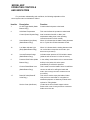
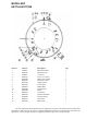
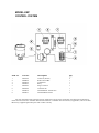
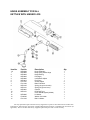
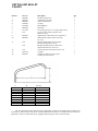
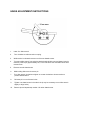
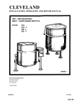
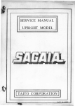
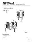
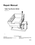
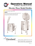
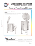
Repair Manual
Pedestal Electric
Self-Contained Kettle
Model KEP
Cleveland Range, Inc.
UNITED STATES
1333 East 179th St., Cleveland, Ohio 44110
Phone: (216)481-4900 • Telex: 98-0546 • FAX: (216) 481-3782
CANADA
Garland Commercial Ranges
1177 Kamato Road
Mississaugha. Ontario. Canada L4W7X4
Phone: (416) 624-0260 • FAX: (416) 624-0623
KET-13
Cleveland WARRANTY AND
LIMITED EXTENDED WARRANTY COVERAGE
LIMITED WARRANTY
Cleveland Range products are warranted to the original purchaser to be free from defects in material
and workmanship under normal use and service for the standard warranty period.
Cleveland Range agrees to repair or replace, at its option, f.o.b. factory, any pan which proves to be
defective due to defects in material or workmanship during the warranty period, providing the equipment
has been unaltered. and has been PROPERLY INSTALLED MAINTAINED, AND OPERATED IN
ACCORDANCE WITH THE CLEVELAND RANGE OWNER'S MANUAL.
CLEVELAND RANGE agrees to pay any FACTORY AUTHORIZED EQUIPMENT SERVICE AGENCY
(within the continental United States. Hawaii, and Canada) for reasonable labor required to repair or
replace, at our option, f.o.b. factory, any part which proves to be defective due to defects in material or
workmanship, during the labor warranty period. This warranty includes travel time not to exceed two
hours and mileage not to exceed 50 miles (100 miles round-trip), but does not include post start-up,
tightening loose fittings, minor adjustments, maintenance, cleaning or descaling.
The standard labor warranty allows factory payment of reasonable labor required to repair or replace
such defective pans. Cleveland Range will not reimburse the expense of labor required for the repair or
replacement of parts after the standard warranty period, unless an Extended Labor Warranty Contract
has been purchased to cover the equipment for the balance of the warranty period from the date of
equipment installation, start-up, or demonstration.
PROPER INSTALLATION IS THE RESPONSIBILITY OF THE DEALER. THE OWNER-USER, OR
INSTALLING CONTRACTOR. AND IS NOT COVERED BY THIS WARRANTY. Many local codes exist,
and it is the responsibility of the owner and installer to comply with these codes. Cleveland Range
equipment is built to comply with applicable standards for manufacturers, including UL, A.G.A., NSF.
ASME/Ntl. Bd., CSA. CGA, ETL. and others.
BOILER (Steam Generator) MAINTENANCE IS THE RESPONSIBILITY OF THE OWNER-USER.
AND IS NOT COVERED BY THIS WARRANTY The use of good quality feed water is the responsibility
of the Owner-User (see Water Quality Requirements below). THE USE OF POOR QUALITY FEED
WATER WILL VOID EQUIPMENT WARRANTIES. Boiler maintenance supplies, including boiler hand
gaskets, are not warranted beyond the first 90 days after the date the equipment is placed into service if
no preventive maintenance records are available showing descaling every 90-120 days.
WATER QUALITY REQUIREMENTS
TOTAL DISSOLVED SOLIDS less than 60 parts per million
TOTAL ALKALINITY
less than 20 parts per million
SILICA
less than 13 parts per million
CHLORIDE
less than 30 parts per million
pH FACTOR
greater than 75
The foregoing shall constitute the sole and exclusive remedy of original purchaser and the fun liability of
Cleveland Range for any breach of warranty. THE FOREGOING IS EXCLUSIVE AND IN LIEU OF ALL OTHER
WARRANTIES. WHETHER WRITTEN. ORAL, OR IMPLIED. INCLUDING ANY WARRANTY OF PERFORMANCE.
MERCHANTABILITY, OR FITNESS FOR PURPOSE, AND SUPERSEDES AND EXCLUDES ANY ORAL
WARRANTIES OR REPRESENTATIONS. OR WRITTEN WARRANTIES OR REPRESENTATIONS. NOT
EXPRESSLY DESIGNATED IN WRITING AS A "WARRANTY" OR "GUARANTEE" OF CLEVELAND RANGE
MADE OR IMPLIED IN ANY MANUAL. LITERATURE. ADVERTISING BROCHURE OR OTHER MATERIALS.
Cleveland Range's liability on any claim of any kind. including negligence, with respect to the goods or services
covered here under. shall in no case exceed the price of the goods or services, or part thereof, which gives rise to
the claim. IN NO EVENT SHALL CLEVELAND RANGE BE LIABLE FOR SPECIAL, INCIDENTAL. OR
CONSEQUENTIAL DAMAGES. OR ANY DAMAGES IN THE NATURE OF PENALTIES.
LIMITED EXTENDED WARRANTY COVERAGE
The purchase of a Limited Extended Warranty Contract extends the standard warranty coverage to the purchased
period of time (one to four years) from the date of installation, start-up, or demonstration, whichever is sooner.
MODEL KEP
OPERATING CONTROLS
AND INDICATORS
For your better understanding and confidence, the following explanation of the
control system used on this kettle is offered.
Item No.
Description
Function
7
On-Off Toggle Switch (Kettle
Controls electrical power to the kettle.
Bottom Dwg.)
2
Solid State Temperature
8
Control (Control System Dwg.) heat increments from Min. to Max. (see
temperature setting chart in the operating
instructions section of this manual).
Heat Indicator Light (Green)
When lit, indicates that the kettle heating elements
12
14
5
2
1-7
This control allows the operator to select kettle
(Kettle Bottom Dwg.)
are on. Cycles On-Off with thermostat control.
Low Water Indicator Light
When lit, indicates that the heating elements have
(Red) (Kettle Bottom Dwg.)
cut out and the unit requires more water. (See
Reservoir Fill procedure).
Vacuum/Pressure Guage
Indicates steam pressure in PSI inside the steam
(Kettle Bottom Dwg.)
jacket as well as vacuum in inches of mercury.
Pressure Relief Valve (Kettle
In the unlikely event that there is an excess steam
Bottom Dwg.)
build-up in the jacket, this valve opens
automatically to relieve this pressure.
Chrome Plated Brass Vent
This is used to vent the kettle if there is insufficient
(Kettle Bottom Dwg.)
vacuum as well as for refilling the kettle with
water. (See Venting Instruction and Reservoir Fill
Procedures ).
This valve is used to empty the kettle of either
Draw-Off Valve (Draw-Off
Valve Dwg.)
Service Cover (Not Shown)
food product or wash water. It is supplied as
standard equipment on Stationary models and is
optional on Tilting kettles.
Located at the front of kettle support column.
Remove this cover for easy access to contactors.
kettle control box etc.
MODEL KEP
KETTLE BOTTOM
Item No.
1
2
3
4
5
6
7
8
9
10
11
12
13
14
15
16
Part No.
FI05025
KE50570
FI05022
KE50556
KE50998
KE50997
KE50504
KE50568
SK50062
KE50988
KE50569
KE50567
KE50558
KE50429
KE00515
KE51005
Description
Bleed Vent Elbow
Bleed Vent Nut
Connector
Probe - Low Water
Safety Valve 55 PSI.
Blow Down Tube
Toggle Switch
L.E.D. Green
Rubber Boot
Potentiometer
Knob
L.E.D. Red
Safety Thermostat
Pressure Guage
Thermistor
Rotary Seal
Qty.
1
1
1
1
1
1
1
1
1
1
1
1
1
1
1
1
Use only replacement parts which are factory supplied as to preserve the certification of Underwriters
Laboratories, American Gas Association. Canadian Standards Association or Canadian Gas Association (as
applicable). The use of other than factory supplied replacement parts will void the warranty.
MODEL KEP
CONTROL SYSTEM
Item No.
Part No.
Description
Qty.
1
2
3
4
5
6
7
8
KE51322
KE00458
KE50752
KE50753
KE51225
KE51226
KE50376
KE50377
Contactor (Furnas)
Kettle Control Box
Transformer
Relay
Edge Connector
Connector Pin
Terminal Block - End Section
Terminal Block Section
2
1
1
1
1
1
1
3
Use only replacement parts which are factory supplied as to preserve the certification of Underwriters Laboratories,
American Gas Association. Canadian Standards Association or Canadian Gas Association (as applicable). The use of other
than factory supplied replacement parts will void the warranty.
HINGE ASSEMBLY FOR ALL
KETTLES WITH HINGED LIDS
Item No.
Part No.
Description
Qty.
1-9
1
2
3
4
5
6
7
8
KE00598
KE50822
KE50824
KE50823
KE50820
KE50819
FA11507
FA11284
KE50122
KE50121
KE50821
KE50151
Hinge Assembly
Body Spring Assist Hinge
Hinge Bearing
Pin(Hinge)
Insert Brass Adjust
End Piece
Screws Adjust
Bolts End Block
Spring (40 gal. and under)
Spring (60 gal. and over)
Cylinder
Knob Ball Type
Cover Handle (Specify Model)
Lid Holder
Washer Lid Holder
Bolt Lid Holder
1
1
1
1
1
1
2
2
1
1
1
1
1
1
1
1
9
10
11
12
13
14
KE00095
FA30500
FA11223
Use only replacement parts which are factory supplied as to preserve the certification of Underwriters
Laboratories, American Gas Association. Canadian Standards Association or Canadian Gas Association (as
applicable). The use of other than factory supplied replacement parts will void the warranty.
ALL KETTLES
PARTS LIST - DRAW-OFF VALVE
Item No.
Part No.
Description
Qty.
1-7
KE50219
KE50972
KE50973
1 1/2" Draw-off Valve Assy.
2" Draw-off Valve Assy.
3" Draw-off Valve Assy.
Body (1 1/2') (N/A, Please order Hem no. 1-7,
Pan no. KE50219)
Body (2") (N/A, Please order Item no. 1 -7,
Part no. KE50972)
Body (3") (N/A, Please order Item no. 1-7,
Pan no. KE50973)
"0"Ring(1 1/2",2'')
"0" Ring (3")
Stem (11/2")
Stem (2")
Stem (3")
Bonnet (1 1/2")
Bonnet (2")
Bonnet (3")
Hex Nut (1 1/2"
Hex Nut (2")
Hex Nut (3")
Knob(1 1/2",2")
Knob(3")
WingNut(1 1/2",2")
Acorn Nut (3")
1
1
1
1
1
2
3
4
5
6
7
FA00111
FA00210
SE50008
SE50009
SE50010
SE50011
SE50012
SE50013
SE50014
SE50015
SE50016
SE50017
SE50018
SE50019
SE50063
1
1
1
1
1
1
1
1
1
1
1
1
1
1
1
1
1
Use only replacement parts which are factory supplied as to preserve the certification of Underwriters Laboratories,
American Gas Association. Canadian Standards Association or Canadian Gas Association (as applicable). The use of other
than factory supplied replacement parts will void the warranty.
KETTLE AND SKILLET
FAUCET
Item No.
1
2
3
4
5
6
7
8
Part No.
SE50020
SE50021
SE50022
FA00016
FA95022
KE51404
see chart
N/A
9
10
KE51401
KE51403
11
N/A
N/A
12
13
14
A
4"
10"
6"
12 1/2"
10 3/4"
5"
24"
20"
12 1/2"
N/A
FA00115
SE50061
B
8"
9"
22"
14"
14"
14"
9"
9"
9"
Description
Hot Water Stem Assy.
Cold Water Stem Assy.
Yoke Connection Kit
"0" Ring
Retaining Ring
Spout Nut
3/4" spout (please see 3/4" spout chart below)
3/4" spout with-Aerator (please order
Item No. 4.5,6,7)
Single Pantry Control Valve (incl. Item No. 2)
Double Pantry Control Valve (incl. Item
No. 1,2.3)
Old Style Single Pantry Control Valve
(please order Item No 4.5.6.7,9)
Old Style Double Pantry Control Valve
(please order Item No. 4.5.6.7.10)
1" Spout (please order Item No. 4,5.6.7.14)
"0" Ring
Adapter (to adapt new style spout
to old style control valve)
Qty.
1
1
1
1
1
1
1
1
1
1
1
1
1
2
1
Part No.
KE50833
KE50832
KE50831
KE50830
KE50829
KE50828
KE50827
KE50826
KE50825
Use only replacement parts which are factory supplied as to preserve the certification of Underwriters
Laboratories, American Gas Association. Canadian Standards Association or Canadian Gas Association (as
applicable). The use of other than factory supplied replacement parts will void the warranty.
KETTLE AND SKILLET
FAUCET
ALL ELECTRIC KETTLES
SERVICING GUIDE
This section contains servicing information intended for use by Authorized
Service Personnel.
Note 1: If Fault Isolation Procedure is required, be sure to start at step #1,
Note 2: On table top kettles the entire control mounting panel may be removed from kettle control
housing for easier troubleshooting and parts replacement.
A/ Problem: Kettle is not heating at all. (Kettle must be on and temperature control set.)
Possible Causes
1.
2.
3.
4.
5.
6.
7.
No incoming power.
Kettle is tilted.
Low water condition.
Defective on/off switch
Defective 12 VDC relay.
Defective safety thermostat.
Defective contactor/s.
8. Defective potentiometer.
9. Defective low water level probe.
10. Defective thermistor
11. Defective 240/16 VAC transformer.
12. Defective control box.
13. Defective elements.
Fault Isolation Procedure
Result Remedy
Step Test
1. Is there proper incoming voltage at terminal
block"?
Yes
Go to step #2.
No
Correct external power supply problem.
Yes
Follow Kettle Filling Procedure. If this does not
correct the problem, go to PROBLEM D
No
Go to step #3.
Yes
Go to step #4.
No
Go to step #7.
Yes
Check contactor contacts for pitting Voltage
across contactor terminals while in a closed
position indicates a poor contact. Replace
contactor/s as necessary. Check elements
for short to ground or an open circuit. If
element/s are defective contact the factory.
Elements are not field replacable.
No
Go to step #5.
2. Is the red LED illuminated?
3. Is the green LED illuminated?
4. Do both contactors energize?
5. Measure continuity across safety thermostat. Is Yes
it an open circuit?
No
6. Is there 120 VAC present across the coils of the Yes
contactors?
No
Replace defective safety thermostat.
Go to step #6.
Replace defective contactor/s.
Replace defective 12 VDC relay.
7.
Remove wire from low water level probe and
ground it to the body of the kettle. Do the
contactors now energize?
8.
Is there 16 VAC present at output of 16 VAC
transformer?
9.
Measure continuity of ON/OFF switch. Is it
operating properly?
Yes
Clean or replace defective low water level
probe. Replace detective red LED.
No
Go to step #8.
Yes
Go to step #9.
No
Replace defective 240/16 VAC transformer.
Yes
Go to step #10.
No
Replace defective ON/OFF switch.
10. Unplug control box and measure the
Yes
resistance across potentiometer. Is it approx.
0 ohms at max. and 50,000 ohms at min.
No
settings?
11. Remove edge connector from control box.
Yes
While kettle is cold or thermistor is removed
and allowed to cool, measure the resistance
between edge connectors pins #2 and #7. Is
it approx. 100,000 ohms?
No
B/ Problem:
Go to step #11.
Replace defective potentiometer.
Spray contact cleaner on control box
terminals and edge connector. Try box
again, if problem still exists, replace
defective control box.
Replace defective thermistor.
Kettle heats too slowly or not hot enough.
(Note: normal max. operating pressure with an empty kettle is 30-35 psi.)
Possible Causes
1. Air in kettle jacket - requires venting.
5.
Defective contactors.
2. Defective safety thermostat.
3. Defective potentiometer.
4. Defective thermistor.
6.
7.
Defective control box.
Defective element/s.
Fault Isolation Procedure
Result Remedy
Step Test
1. In a cold state, does the pressure gauge
read in the green zone?
Yes
Go to step #2.
No
2. Do the contactors shut off too early? (before
reaching normal max. operating pressure)
Yes
There is air present in the jacket of the
kettle. Follow Kettle Venting Procedure. If
constant venting is required, there is a leak
that should be corrected.
Go to step #3.
No
3. Does the green LED remain illuminated after
the contactors shut off?
Yes
Check contactor contacts for pitting. Voltage
across terminals of contactor while
energized signifies a poor contact. Replace
contactor/s as necessary. Check elements
for short to ground or open circuit. If
elements are defective, contact the factory
Elements are not field replacable.
Replace defective safety thermostat.
No
Go to step #4.
4.
5.
6
Unplug control box and measure the
resistance across potentiometer. Is it approx.
0 ohms at max. and 50.000 ohms at min.
settings?
Remove kettle thermistor and allow to cool.
Remove edge connector from control box.
Test resistance across edge connectors pins
#2. and #7. Is it approx. 100.000 ohms?
Yes
Go to step #5.
No
Replace defective potentiometer.
Yes
Go to step #6.
No
Replace defective thermistor.
Turn the potentiometer on the control box
clockwise to increase the max. operating
temperature. Does the kettle now achieve
max. operating pressure of 30-35 psi in an
empty kettle?
Yes
Kettle is operating properly.
No
Spray contact cleaner on control box
terminals and edge connector; Try box
again. If problem still exists, replace
defective control box.
C/ Problem: Kettle is overheating.
Possible Causes
1 Defective thermistor.
2 Defective potentiometer.
3. Defective 12 VDC relay.
4. Defective control box.
Fault Isolation Procedure
Step Test
Result
Remedy
1. Does the green LED turn off even though the
contactors remain energized?
Yes
Replace defective 12 VDC relay.
No
Go to step #2.
2. Unplug the control box and measure the
resistance across the potentiometer. Is the
resistance approx. 0 ohms at max. and 50.000
ohms at mm. settings?
3. Remove kettle thermistor and allow to cool.
Remove edge connector from control box.
Test resistance across edge connectors pins #2
and #7. Is it approx. 100,000 ohms?
Yes
Go to step #3.
No
Replace defective potentiometer.
Yes
Go to step #4.
No
Replace defective thermistor.
4. Turn the potentiometer on the control box
counter-clockwise to decrease the max. operating
temperature. Does the kettle continue to
overheat?
Yes
Spray contact cleaner on control box
terminals and edge connector Try box
again. If problem still exists, replace
defective control box.
No
Kettle is operating properly.
HINGE ADJUSTMENT INSTRUCTIONS
1.
2.
Insert 3/8" Allen wrench.
Turn clockwise to relieve tension on spring.
3.
While tension is released remove one of the two slotted screws.
4.
To prevent Allen wrench from springing back abruptly while the second slotted screw is
removed, insert a pin (approximately 1/8") in the hole where the first slotted screw was
removed from.
5.
Remove second slotted screw.
6
While holding Allen wrench remove pin.
7.
Turn Allen wrench clockwise to tighten or counter-clockwise to loosen tension to
produce desired effect.
8.
Re-insert pin in one of the two holes.
9.
Tighten one slotted screw in the other hole (it may be necessary to turn Allen wrench
slightly to align holes.)
10.
Remove pin and repeat step number 9 for other slotted screw.
ELECTRIC KETTLE
WIRING DIAGRAM
PEDESTAL ELECTRIC STEAM KETTLES
MAINTENANCE
Draw-off Valve Maintenance:
To correct a leak at the draw-off valve, the source of the leak must first be determined. Leaks from around the valve stem
are corrected by simply replacing the "0" ring. Faulty seating of the valve stem disc against the valve body seat may cause
dripping from the valve even when the valve is tightly closed. This can often be corrected by cleaning any residue from the
disc and seat with a piece of very fine emery cloth.
KETTLE VENTING INSTRUCTIONS
If the vacuum/pressure gauge reading is in the "vent air" zone, it means that air has entered the steam/water jacket,
resulting in little or no vacuum. This reduces kettle efficiency by slowing its heating process, as the water cannot boil when
air is present in the jacket. To remedy this situation, the following venting procedures should be followed:
1. With the temperature control knob set at number 6, heat the empty kettle until the vacuum / pressure gauge indicates 510 psi.
2. Release steam and air from the steam/water jacket by loosening, one-half turn. the 7/16" chrome-plated brass venting
valve nut (located at the rear of the kettle) for 3-6 seconds.
3. Tighten the vent valve nut, being careful not to overtighten.
The kettle's steam/water jacket should now be free of air. At room temperature, the pressure gauge needle should rest in
the green zone, indicating a vacuum in the kettle's jacket. To check the gauge for proper vacuum after venting, the
temperature can be quickly reduced by filling the kettle with cold water.
If the kettle will not hold a vacuum, test for leaks at the vent valve, the safety valve, the probe, and the vacuum/pressure
gauge fittings. We suggest mixing a 50/50 solution of liquid detergent and water while heating the kettle to at least 5 psi
pressure. Then, shut off power to the kettle at the fused disconnect switch. The soapy solution should be applied to the
suspected area while the gauge shows at least 5 psi pressure. Any bubbles which appear will indicate a leak.
WARNING: The fused disconnect switch must be switched off before removing the kettle's bottom cover, which exposes
dangerous high voltage.
RESERVOIR FILL PROCEDURES
The reservoir's water level must be maintained at the proper level to submerge the heater elements. Under normal
operating conditions, the sealed water reservoir should never require the addition of water. If the red "low water" light comes
on . .ring use (while the kettle is in an upright position), the water level has reached a critically low level. The low water
protection control has automatically shut off the heater elements. The following procedure must be completed before further
use:
NOTE: Ensure that the red "low water" light is on when the kettle is upright. On tilting kettles, it is normal for the red light to
come on when the kettle is in a tilted position, as the elements are not submerged in water at this point.
1 Shut off power to the kettle at the fused disconnect
switch.
When Red
When the Water
2 Remove the bottom cover. (Tilting kettles can be tilted
"Low
Water
Light"
Reservoir is
forward for easier access to the cover. Tilt the kettle back
Kettle
Comes
On,
Add
Completely Empty,
to the upright position once the cover has been removed).
Capacity
Distilled Water
Add Formula*
3 Unscrew and remove the chrome-plated brass venting
2 gal
50 oz.
120oz.
valve nut located on the back of the kettle.
5 gal
70 oz
160oz
4 Hold the safety valve open while adding distilled water
10 gal
120oz
2 gal
through the vent hole. using a funnel.
20 gal.
1.0 gal.
3 gal.
30
gal
1.8
gal
4 1/4 gal
5 Place the chrome-plated brass venting valve nut into the
40 gal
2.0 gal
4 1/2 gal.
water fill hole and carefully tighten. Do not over-tighten
60 gal.
2.1 gal
5 1/2 gal.
Replace the bottom cover.
80 gal
2.6 gal.
6 1/4 gal.
6 Restore power to the kettle at the fused disconnect switch. 100 gal
2.8 gal
7 gal.
7 The kettle must now be vented. Refer to the "Kettle Venting
*Anti-freeze and rust
Instructions".
Inhibitor
CAUTION: Only distilled water should be used when adding
water to a partially filled water reservoir. Local
tap water conditions may cause kettle damage Rust Inhibitor: 3 oz.
Anti-Freeze:
64 oz.
which is not covered under warranty.
Tap Water:
448 oz.
formula:
( .5 gal.)
(3.5 gal.)
=
=
=
0.6%
12.4%
87.0%