1
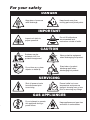
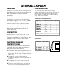
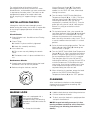
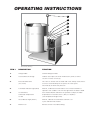
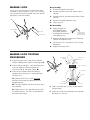
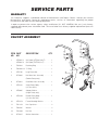
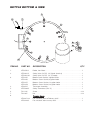
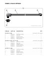
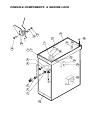
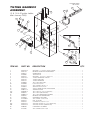
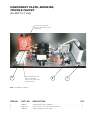
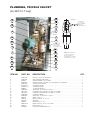
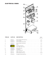
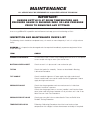
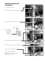
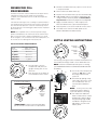
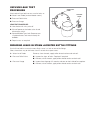
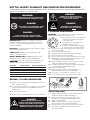
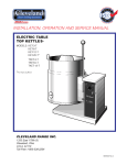
Operators Manual
Installation, Operation & Service
Electric Table Top Kettles
MODELS:
Single Kettles
KET-3-T
KET-6-T
KET-12-T
KET-20-T*
Twin Kettles
TKET-3-T
TKET-6-T
TKET-12-T
*Floor Type Leg Mount
™
Cleveland
Enodis
1333 East 179th St., Cleveland, Ohio, U.S.A. 44110
Phone: (216) 481-4900 Fax: (216) 481-3782
Visit our web site at www.clevelandrange.com
SE95004 Rev. 8
For your safety
DANGER
Keep clear of pressure
relief discharge.
Keep hands away from
moving parts and pinch points.
IMPORTANT
Do not fill kettle above
recommended level
marked on outside of kettle.
Inspect unit daily for
proper operation.
CAUTION
Surfaces may be
extremely hot! Use
protective equipment.
Wear protective equipment
when discharging hot product.
Do not lean on or place
objects on kettle lip.
Stand clear of product
discharge path when
discharging hot product.
SERVICING
Shut off power at main
fuse disconnect prior
to servicing.
0
Ensure kettle is at room
temperature and pressure
gauge is showing zero or less
prior to removing any fittings.
GAS APPLIANCES
Do not attempt to operate
this appliance during a
power failure.
Keep appliance and area free
and clear of combustibles.
INSTALLATION
GENERAL
INSTALLATION
Installation of the kettle must be accomplished by
qualified electrical installation personnel working
to all applicable local and national codes.
Improper installation of product could cause injury
or damage.
The first installation step is to refer to the
Specification Sheets or Specification Drawings for
detailed clearance requirements of the kettle.
Next, carefully cut open the shipping carton for
easy removal of the kettle.
This equipment is built to comply with applicable
standards for manufacturers. Included among
those approval agencies are: UL, NSF, ASME/Ntl.
Bd., CSA, CGA, ETL, and others. Many local
codes exist, and it is the responsibility of the
owner/installer to comply with these codes.
CLEARANCE REQUIREMENTS
Note: Maximum voltage for LVD (low volt
directive for Europe) to be 440 volts for CE
marked appliances.
INSPECTION
Model #
Back*
Left Side Right Side
KET-3-T
2 1/4”
0
0
KET-6-T
2 3/4”
0
0
KET-12-T
5 1/2”
0
0
KET-20-T
8”
0
0
TKET-3-T
6 5/8”
0
0
TKET-6-T
7 1/8”
0
0
TKET-12-T
9 7/8”
0
0
Before unpacking visually inspect the unit for
evidence of damage during shipping.
* From back of mounting base.
If damage is noticed, do not unpack the unit, follow
Shipping Damage Instructions shown below.
POUR PATH
SHIPPING DAMAGE
INSTRUCTIONS
If shipping damage to the unit is discovered or
suspected, observe the following guidelines in
preparing a shipping damage claim.
1. Write down a description of the damage or the
reason for suspecting damage as soon as it is
discovered. This will help in filling out the claim
forms later.
2. As soon as damage is discovered or
suspected, notify the carrier that delivered the
shipment.
3. Arrange for the carrier's representative to
examine the damage.
4. Fill out all carrier claims forms and have the
examining carrier sign and date each form.
Kettle Size
Min. Max.
3 Gallon
15 1/2” 32”
6 Gallon
17 1/4” 36”
12 Gallon
18”
38”
20 Gallon
22”
45”
Min.
Max.
ASSEMBLY
Position on a firm, level surface, and bolt two
flange feet in place. Once the kettle is secure,
screw tilt handle into the threaded hole provided
at the right of kettle.
Table-Top Models (3, 6 & 12 gallon)
14.5"
1.25"
1.25"
1.25"
ELECTRICAL
This kettle is built to comply with applicable
standards of manufacturers. Included among
these approval agencies are UL, NSF, ASME/Ntl.
Bd., CSA, ETL, and others. Many local codes
exist, and it is the responsibility of the owner and
installer to comply with these codes.
TKET-3-T
TKET-6-T
TKET-12-T
10"
12.5"
1.25 "
A
Model #
A
B
C
TKET-3-T
18"
2.25"
1.25"
TKET-6-T
24"
4.63"
4.63"
TKET-12-T
30"
7.75"
7.75"
Base Mounting Diagram
Table-top models (3, 6 & 12 gallon - single and twin)
must be positioned on a firm, level stand, or existing
counter top, and bolted in place. These models are
supplied with four threaded mounting bushings
welded to the underside of the base. An optional
support stand with level adjustable legs is available.
Once the kettle is secure, screw tilt handle into the
threaded hole provided at the right side of kettle.
Floor Type Leg Mount Models (20 gallon)
1.25"
1.25"
28.5"
2.25"
The electrical supply must match the power
requirements specified on the kettle’s rating plate.
The copper wiring must be adequate to carry the
required current at the rated voltage.
Note: Maximum voltage for LVD (low volt
directive for Europe) to be 440 volts for CE
marked appliances.
WIRE CONNECTION
If unit does not have cord and plug option, remove
the four screws securing the console cover and
remove the cover. A wiring diagram is affixed to
the underside of the cover. Feed permanent
copper wiring through the cut-out in the rear or
bottom of the console, and fasten to the three
connection terminal block, which is mounted on
the top of the console’s control panel. Be sure to
connect the ground wire to the separate ground
terminal connector (ground lug). Replace console
cover and secure it with the four screws.
THREE
PHASE
RED
YELLOW
BLACK
SINGLE
PHASE
RED
C
BLACK
B
BLUE
5/16" - 18
threaded
bushings
18"
RED
1.25"
1.25 "
ENSURE THE ELECTRICAL SUPPLY MATCHES
THE KETTLE'S REQUIREMENTS AS STATED
ON THE RATING LABEL.
12.5"
BLACK
10"
BLUE
KET-3-T
KET-6-T
KET-12-T
RED
YELLOW
BLACK
KET-20-T
12"
14.5"
1.25"
32"
Base Mounting Diagram
L1 L2 L3
L1
L2
The kettle is wired for 3-phase operation at the
factory. For single phase operation, rewire the
terminal block to that shown in the above diagram.
WATER
The sealed jacket of the electric kettle is
precharged with the correct amount of a water
based formula, and therefore, no water connection
is required to the kettle jacket. The kettle can be
equipped with optional hot and/or cold water
faucet, requiring 1/2" copper tubing as supply
lines.
INSTALLATION CHECKS
Although the kettle has been thoroughly tested
before leaving the factory, the installer is responsible
for ensuring the proper operation of kettle once
installed.
Visual Checks
1. Check Marine Lock. See Marine Lock Testing
Procedure.
2. Check Tilting:
Vacuum/Pressure Gauge (2). The gauge's
needle should be in the green zone. If the
needle is in the "VENT AIR" zone, follow Kettle
Venting Instructions.
3. Turn the kettle's ON/OFF Switch/Solid State
Temperature Control (5) to "1" (Min.). The Heat
Indicator Light (Green) (6) should remain lit,
indicating the element is on, until the set
temperature is reached (130°F/54°C). Then the
green light will cycle on and off, indicating the
element is cycling on and off to maintain
temperature.
4. Tilt the kettle forward. After a few seconds the
Low Water Indicator Light (Red) (4) should be lit
when the kettle is in a tilted position. This light
indicates that the element has automatically
been shut off by the kettle's safety circuit. This is
a normal condition when the kettle is in a tilted
position.
A/ Handle is in place and firmly tightened.
B/ Kettle tilts smoothly and freely.
3. Insure there are:
A/ Four screws securely holding the console
cover.
B/ The bottom cover is in place and held with a
nut.
Performance Checks
1. Supply power to the kettle by placing the fused
disconnect switch to the "ON" position.
2. Before turning the kettle on, read the
150
30
300
40
0
50
IR
NT A
VE
0
250
20
10
60
psi
6. Turn the ON/OFF Switch/Solid State Temperature
Control (5) to "10" (Max.) and allow the kettle to
preheat. The green light should remain on until
the set temperature (260°F/127°C) is reached.
Then the green light will cycle ON and OFF,
indicating the element is cycling ON and OFF to
maintain temperature. Fill the kettle with cold
water to the steam jacket’s welded seam. Refer
to the Temperature Range Chart for the time
required to bring the water to a boil.
7. When all testing is complete, empty the kettle
and turn the ON/OFF Switch/Solid State
Temperature Control (5) to the “OFF” position.
200
100
50
5. Raise the kettle to the upright position. The Low
Water Indicator Light (Red) (4) should go out
when the kettle is upright.
350
400
kPa
CLEANING
After installation the kettle must be thoroughly
cleaned and sanitized prior to cooking. See
Cleaning Instructions.
MARINE LOCK
2. Hold the latch down to unlock tilting mechanism.
3. Pull the handle to tilt kettle.
LATCH
Your unit is equipped with a
marine lock to prevent
accidental tilting. The following
procedure should be used to tilt
the kettle.
1. Grasp the tilt handle.
4. To lock, return the kettle to its upright position
and push handle back.
NOTE: Inspect lock daily to ensure it is free
moving and does not bind or stick. Clean lock
if necessary (see Cleaning Instructions for
details).
OPERATING INSTRUCTIONS
1
2
3
4
5
6
7
General Parts Drawing
ITEM #
DESCRIPTION
FUNCTION
1.
Tilting Handle
Used for tilting the kettle.
2.
Vacuum/Pressure Gauge
Indicate steam pressure in PSI inside steam jacket as well as
vacuum in inches of mercury.
3.
Pressure Relief Valve
(not shown)
This valve is used to vent the kettle and in the unlikely event there is
an excess steam build-up in the jacket, this valve opens
automatically to relieve this pressure.
4.
Low Water Indicator Light (Red)
When lit, it indicates that the kettle is low on water and will not
operate in this condition. This will also light when the kettle is tilted.
5.
On-Off Switch/
Solid State Temperature
Control
Turns kettle ON/OFF and allows the operator to adjust the kettle
temperature in increments from 1 (Min.) to 10 (Max.).
(see Temperature Range Chart).
6.
Heat Indicator Light (Green)
When lit, indicates that the kettle's element is on.
Cycles ON-OFF with element.
7.
Marine Lock
Prevents unit from accidental tilting.
OPERATING THE KETTLE
DO NOT LEAN ON OR PLACE OBJECTS ON
KETTLE LIP. SERIOUS INJURY COULD RESULT
IF KETTLE TIPPED OVER, SPILLING HOT
CONTENTS.
1. Before turning kettle on, read the
Vacuum/Pressure Gauge (2). The gauges
needle should be in the green zone. Once
heated, the kettle's normal maximum
operating pressure is approximately 10-12 psi,
while cooking a water base product.
2. Ensure that the electrical service to the kettle
is turned on at the fused disconnect switch.
Temperature
Control
Setting
1. (Min.)
2.
3.
4.
5.
6.
7.
8.
9.
10. (Max.)
Approximate
Product Temperature
°F
°C
130
145
160
170
185
195
210
230
245
260
54
63
71
77
85
91
99
110
118
127
NOTE: Certain combinations of ingredients will
result in temperature variations
Temperature Range Chart
3. Preheat the kettle by turning the ON/OFF
Switch/Solid State Temperature Control (5) to
the desired temperature setting (see above
"Temperature Range Chart"). The Heat
Indicator Light (Green) (6) will remain lit,
indicating the element is on, until the
temperature setting is reached. When the
green light goes off, the elements are off, and
preheating is complete.
NOTE: When cooking egg and milk products, the
kettle should not be preheated, as products of this
nature adhere to hot cooking surfaces. These types of
food should be placed in the kettle before heating is
begun.
4. Place food product into the kettle. The Heat
Indicator Light (Green) (6) will cycle on and
off indicating the elements are cycling on and
off to maintain the set temperature.
NOTE: Do not fill kettle above
recommended level marked on
outside of kettle.
NOTE: The Low Water Indicator Light (Red) (4)
should not be lit when kettle is in upright position
during operation. This light indicates that the
elements have been automatically shut off by the
kettle's safety circuit. It is, however, normal for the
red light to come on when the kettle is in a tilted
position.
5. When cooking is completed turn ON/OFF
Switch/Solid State Temperature Control (5) to
the "OFF' position.
6. Pour the contents of the kettle into an
appropriate container by tilting the kettle
forward. Care should be taken to pour slowly
enough to avoid splashing off the product.
NOTE: As with cleaning food soil from any
cookware, an important part of kettle cleaning is to
prevent food from drying on. For this reason, cleaning
should be completed immediately after cooked foods
are removed.
APPROXIMATE BOILING
TIMES
The accompanying chart shows approximate
times required for electric kettles of various
capacities to boil water. The ON/OFF Switch/Solid
State Temperature Control must be set at “10”
(Max.) throughout the heat-up period. Water will
boil about 1/3 faster if the kettle is filled only to the
outer steam jacket’s welded seam resulting in a
kettle filled to 2/3 capacity.
Kettle Capacity
Minutes
3 gallon/11 litre
15
6 gallon/23 litre
20
12 gallon/45 litre
25
20 gallon/80 litre
40
Approximate Boiling Times
CLEANING INSTRUCTIONS
CLEANING INSTRUCTIONS
CAUTION
1. Turn unit off.
SURFACES MAY
BE EXTREMELY HOT!
2. Remove drain screen (if applicable). Thoroughly
wash and rinse the screen either in a sink or a
dishwasher.
CARE AND CLEANING
3. Prepare a warm water and mild detergent solution in
the unit.
Cooking equipment must be cleaned regularly to
maintain its fast, efficient cooking performance and
to ensure its continued safe, reliable operation. The
best time to clean is shortly after each use (allow
unit to cool to a safe temperature).
4. Remove food soil using a nylon brush.
5. Loosen food which is stuck by allowing it to soak at
a low temperature setting.
6. Drain unit.
WARNINGS
➩
7. Rinse interior thoroughly.
8. If the unit is equipped with a Tangent Draw-Off
Valve, clean as follows:
Do not use detergents or
cleansers that are chloride
based or contain quaternary
salt.
a) Disassemble the draw-off valve first by turning
the valve knob counter-clockwise, then turning
the large hex nut counter-clockwise until the
valve stem is free of the valve body.
Chloride Cleaners
➩
b) In a sink, wash and rinse the inside of the valve
body using a nylon brush.
Do not use a metal bristle
brush or scraper.
c) Use a nylon brush to clean tangent draw-off tube.
d) Rinse with fresh water.
e) Reassemble the draw-off valve by reversing the
procedure for disassembly. The valve's hex nut
should be hand tight only.
Wire Brush &
➩
Steel wool should never be
used for cleaning the stainless
steel.
9. If the unit is equipped with a Butterfly Valve, clean
as follows:
a) Place valve in open position.
b) Wash using a warm water and mild detergent
solution.
Steel Pads
c) Remove food deposits using a nylon brush.
➩
Unit should never be cleaned
with a high pressure spray
hose.
d) Rinse with fresh water.
e) Leave valve open when unit is not in use.
10. Using mild soapy water and a damp sponge, wash
the exterior, rinse, and dry.
NOTES
High Pressure
Spray Hose
➩
➩ For more difficult cleaning applications one of the
following can be used: alcohol, baking soda, vinegar,
or a solution of ammonia in water.
Do not leave water sitting in unit
when not in use.
➩ Leave the cover off when the kettle is not in use.
➩ For more detailed instructions refer to the Nafem
Stainless Steel Equipment Care and Cleaning manual
(supplied with unit).
Stagnant
Water
6
STAINLESS STEEL EQUIPMENT CARE AND CLEANING
(Suppied courtesy of Nafem. For more information visit their web site at www.nafem.org)
Contrary to popular belief, stainless steels ARE susceptible to rusting.
4. Treat your water.
Though this is not always practical, softening hard water can do much
to reduce deposits. There are certain filters that can be installed to
remove distasteful and corrosive elements. To insure proper water
treatment, call a treatment specialist.
Corrosion on metals is everywhere. It is recognized quickly on iron and
steel as unsightly yellow/orange rust. Such metals are called “active”
because they actively corrode in a natural environment when their atoms
combine with oxygen to form rust.
Stainless steels are passive metals because they contain other metals, like
chromium, nickel and manganese that stabilize the atoms. 400 series
stainless steels are called ferritic, contain chromium, and are magnetic;
300 series stainless steels are called austenitic, contain chromium and
nickel; and 200 series stainless, also austenitic, contains manganese,
nitrogen and carbon. Austenitic types of stainless are not magnetic, and
generally provide greater resistance to corrosion than ferritic types.
With 12-30 percent chromium, an invisible passive film covers the steel’s
surface acting as a shield against corrosion. As long as the film is intact
and not broken or contaminated, the metal is passive and stain-less. If the
passive film of stainless steel has been broken, equipment starts to
corrode. At its end, it rusts.
5. Keep your food equipment clean.
Use alkaline, alkaline chlorinated or non-chloride cleaners at
recommended strength. Clean frequently to avoid build-up of hard,
stubborn stains. If you boil water in stainless steel equipment,
remember the single most likely cause of damage is chlorides in the
water. Heating cleaners that contain chlorides have a similar effect.
6. Rinse, rinse, rinse.
If chlorinated cleaners are used, rinse and wipe equipment and
supplies dry immediately. The sooner you wipe off standing water,
especially when it contains cleaning agents, the better. After wiping
equipment down, allow it to air dry; oxygen helps maintain the
stainless steel’s passivity film.
Enemies of Stainless Steel
There are three basic things which can break down stainless steel’s
passivity layer and allow corrosion to occur.
7. Never use hydrochloric acid (muriatic acid) on stainless steel.
8. Regularly restore/passivate stainless steel.
1. Mechanical abrasion
2. Deposits and water
Recommended cleaners for specific situations
3. Chlorides
Job
Cleaning Agent
Comments
Mechanical abrasion means those things that will scratch a steel surface.
Steel pads, wire brushes and scrapers are prime examples.
Routine cleaning
Soap, ammonia,
detergent, Medallion
Apply with cloth or sponge
Fingerprints & smears
Arcal 20, Lac-O-Nu
Ecoshine
Provides barrier film
Stubborn stains &
discoloration
Cameo, Talc, Zud,
First Impression
Rub in direction of polish lines
Grease & fatty acids,
blood, burnt-on-foods
Easy-off, De-Grease
It Oven Aid
Excellent removal on all finishes
Grease & oil
Any good
commercial detergent
Apply with sponge or cloth
Restoration/Passivation
Benefit, Super Sheen
Water comes out of the faucet in varying degrees of hardness. Depending
on what part of the country you live in, you may have hard or soft water.
Hard water may leave spots, and when heated leave deposits behind that
if left to sit, will break down the passive layer and rust stainless steel. Other
deposits from food preparation and service must be properly removed.
Chlorides are found nearly everywhere. They are in water, food and table
salt. One of the worst chloride perpetrators can come from household and
industrial cleaners.
So what does all this mean? Don’t Despair!
Here are a few steps that can help prevent stainless steel rust.
1. Use the proper tools.
When cleaning stainless steel products, use non-abrasive tools. Soft
cloths and plastic scouring pads will not harm steel’s passive layer.
Stainless steel pads also can be used but the scrubbing motion must
be in the direction of the manufacturers’ polishing marks.
2. Clean with the polish lines.
Some stainless steel comes with visible polishing lines or “grain.”
When visible lines are present, always scrub in a motion parallel to the
lines. When the grain cannot be seen, play it safe and use a soft cloth
or plastic scouring pad.
Review
1. Stainless steels rust when passivity (film-shield) breaks down as a
result of scrapes, scratches, deposits and chlorides.
2. Stainless steel rust starts with pits and cracks.
3. Use the proper tools. Do not use steel pads, wire brushes or scrapers
to clean stainless steel.
4. Use non-chlorinated cleaners at recommended concentrations. Use
only chloride- free cleaners.
5. Soften your water. Use filters and softeners whenever possible.
6. Wipe off cleaning agent(s) and standing water as soon as possible.
Prolonged contact causes eventual problems.
3. Use alkaline, alkaline chlorinated or non-chloride containing cleaners.
While many traditional cleaners are loaded with chlorides, the industry
is providing an ever-increasing choice of non-chloride cleaners. If you
are not sure of chloride content in the cleaner used, contact your cleaner
supplier. If your present cleaner contains chlorides, ask your supplier if
they have an alternative. Avoid cleaners containing quaternary salts; it
also can attack stainless steel and cause pitting and rusting.
To learn more about chloride-stress corrosion and how to prevent it,
contact the equipment manufacturer or cleaning materials supplier.
Developed by Packer Engineering, Naperville, Ill., an independent testing
laboratory.
MARINE LOCK
Disassembly
Use a small nylon bristle brush to remove food
and debris from pivot point. If lock is still sticking
have maintenance disassemble and clean pieces
individually and reassemble.
1. Disconnect power from kettle.
Latch
2. Remove console cover from top of kettle's
console.
3. Remove locknut and lockwasher from inside
console.
4. Remove shoulder bold from latch.
5. Clean all parts.
Re-Assembly
Shoulder Bolt
Locknut
Lockwasher
6. Apply locktight to
shoulderbolt where
illustrated. Replace
shoulder bolt and latch
and tighten firmly.
Carefully apply
locktight to the
final two threads.
7. Replace lockwasher and locknut inside the
console and tighten firmly.
8. Test Marine Lock. See Marine Lock Testing
Procedure.
9. Replace console cover.
MARINE LOCK TESTING
PROCEDURE
Stop Pin on
Sidebox
Marine Lock
(Latch)
1. Check that lock clears stop pin on side box
without rubbing when kettle is tilted (Figure A).
2. Check side to side play. Lock should remain
fully over stop pin when pushed to it's
maximum side to side play (Figure B).
Figure A
(Side View)
Lockwasher
3. Check that the kettle when pushed fully
upright moves the lock to a closed position.
To check this:
A/ Hold the latch firmly in the unlocked
position while tilting the kettle back to an
upright position.
B/ The kettle sidebox will force the lock into a
new position.
C/ Hold the lock in this position and try to tilt
the kettle forward. The latch should prevent
the kettle from tilting.
Side to Side Play
Locknut
Side Box
Shoulder Bolt
Figure B
(Top View)
Console
4. Check shoulder bolt is firmly seated against
console body.
5. Check on inside of console box that shoulder
bolt locknut is secure.
SERVICE PARTS
WARRANTY
Our Company supports a worldwide network of Maintenance and Repair Centers. Contact your nearest
Maintenance and Repair Centre for replacement parts, service, or information regarding the proper
maintenance and repair of your cooking equipment
In order to preserve the various agency safety certification (UL, NSF, ASME/Ntl. Bd., etc.), only factorysupplied replacement parts should be used. The use of other than factory supplied replacement parts will
void warranty.
FAUCET ASSEMBLY
1
2
1
ITEM PART
NO. NO.
DESCRIPTION
QTY.
3
4
2
5
3
6
1.
KE50825-2
3/4" Spout (KET-3/6/12/20-T) . . . . . . . .1
KE50825-9
3/4" Spout (TKET-3/6/12-T) . . . . . . . . .1
2.
FA95022
Retaining Ring . . . . . . . . . . . . . . . . . .1
3.
FA05002-19 "O" Ring . . . . . . . . . . . . . . . . . . . . . . . .1
4.
KE51736
4
6
10
7
11
Long Faucet Nut . . . . . . . . . . . . . . . . .1
9
8
12
13
5.
SE50020
Hot Water Stem Assembly . . . . . . . . .1
(Double Pantry only)
6.
SE50021
Cold Water Stem Assembly . . . . . . . .1
7.
KE51401
Single Pantry Body . . . . . . . . . . . . . . .1
(c/w Item No. 6)
8.
KE50335
Adapter Washer . . . . . . . . . . . . . . . . .1
(Single Pantry only)
9.
KE51403
Double Pantry Body . . . . . . . . . . . . . .1
(c/w Item No. 5&6)
10.
KE54159
Faucet Mounting Bracket . . . . . . . . . .1
11.
FA11258
Hex Cap Screw . . . . . . . . . . . . . . . . . .2
12.
FA30505
Washer . . . . . . . . . . . . . . . . . . . . . . . .2
13.
FA21008
Hex Nut . . . . . . . . . . . . . . . . . . . . . . . .2
14.
SE50447
Washer Horseshoe . . . . . . . . . . . . . . .1
10
11
12
13
14
KETTLE BOTTOM & SIDE
1
6
7
3
Element
Terminals
4
8
2
5
ITEM NO.
PART NO.
DESCRIPTION
1.
2.
KE50556-1
KE54941-5
KE54941-31
KE52455
KE52456
KE52457
KE52459
KE00515
KE55069-5
FA11145
FA21007
Probe, Low Water . . . . . . . . . . . . . . . . . . . . . . . . . . . . . . . . . . . . . . . . . .1
Safety Valve, 50 PSI, 1/2" (North America) . . . . . . . . . . . . . . . . . . . . . .1
Safety Valve, 50 PSI, 1/2", (Europe) . . . . . . . . . . . . . . . . . . . . . . . . . . . .1
Bottom Cover Gasket, 3 gallon kettle . . . . . . . . . . . . . . . . . . . . . . . . . .1
Bottom Cover Gasket, 6 gallon kettle . . . . . . . . . . . . . . . . . . . . . . . . . .1
Bottom Cover Gasket, 12 gallon kettle . . . . . . . . . . . . . . . . . . . . . . . . .1
Bottom Cover Gasket, 20 gallon kettle . . . . . . . . . . . . . . . . . . . . . . . . .1
Thermistor Assembly . . . . . . . . . . . . . . . . . . . . . . . . . . . . . . . . . . . . . . .1
Safety Thermostat (140º C) . . . . . . . . . . . . . . . . . . . . . . . . . . . . . . . . . .1
Screw . . . . . . . . . . . . . . . . . . . . . . . . . . . . . . . . . . . . . . . . . . . . . . . . . .2-12
Nut . . . . . . . . . . . . . . . . . . . . . . . . . . . . . . . . . . . . . . . . . . . . . . . . . . . .2-12
Pressure Gauge
For units built prior to February 2005 . . . . . . . . . . . . . . . . . . . . . . . . . . .1
For units built after January 2005 . . . . . . . . . . . . . . . . . . . . . . . . . . . . . .1
3.
4.
5.
6.
7.
8.
KE000714-4
KE50429-5
QTY.
CORD & PLUG OPTION
1
2
4
5
3
Not available for KET-20-T or Twin Kettles
ITEM NO.
PART NO.
FOR KET-6-T (SW)
1.
KE02113-1
2.
KE54819-1
3.
KE54820-1
4.
KE54821-2
5.
KE54721-3
DESCRIPTION
QTY.
(200-240VAC, 3PH, 50/60Hz
Cord Plug Assembly . . . . . . . . . . . . . . . . . . . . . . . . . . . . . . . . . . . . . . . .1
Plug (30A) . . . . . . . . . . . . . . . . . . . . . . . . . . . . . . . . . . . . . . . . . . . . . . . .1
Receptacle (30A) . . . . . . . . . . . . . . . . . . . . . . . . . . . . . . . . . . . . . . . . . .1
Electrical Cord (10/4) . . . . . . . . . . . . . . . . . . . . . . . . . . . . . . . . . . . . . . .1
Cord Connector . . . . . . . . . . . . . . . . . . . . . . . . . . . . . . . . . . . . . . . . . . .1
KE02113-2
KE54819-2
KE54820-2
KE54821-3
KE54721-4
(200-240VAC, 3PH, 50/60Hz
Cord Plug Assembly . . . . . . . . . . . . . . . . . . . . . . . . . . . . . . . . . . . . . . . .1
Plug (50A) . . . . . . . . . . . . . . . . . . . . . . . . . . . . . . . . . . . . . . . . . . . . . . . .1
Receptacle (50A) . . . . . . . . . . . . . . . . . . . . . . . . . . . . . . . . . . . . . . . . . .1
Electrical Cord (8/4) . . . . . . . . . . . . . . . . . . . . . . . . . . . . . . . . . . . . . . . .1
Cord Connector . . . . . . . . . . . . . . . . . . . . . . . . . . . . . . . . . . . . . . . . . . .1
FOR KET-12-T (HW)
1.
KE02113-3
2.
KE54819-2
3.
KE54820-2
4.
KE54821-4
5.
KE54721-5
(200-240VAC, 3PH, 50/60Hz
Cord Plug Assembly . . . . . . . . . . . . . . . . . . . . . . . . . . . . . . . . . . . . . . . .1
Plug (50A) . . . . . . . . . . . . . . . . . . . . . . . . . . . . . . . . . . . . . . . . . . . . . . . .1
Receptacle (50A) . . . . . . . . . . . . . . . . . . . . . . . . . . . . . . . . . . . . . . . . . .1
Electrical Cord (6/4) . . . . . . . . . . . . . . . . . . . . . . . . . . . . . . . . . . . . . . . .1
Cord Connector . . . . . . . . . . . . . . . . . . . . . . . . . . . . . . . . . . . . . . . . . . .1
FOR KET-6-T (HW), KET-12-T (SW),
1.
2.
3.
4.
5.
CONSOLE COMPONENTS & MARINE LOCK
19
24
21
17
14
7
20
18
16
8
5 6
9
15
10
11
4
13
6
25
23
3
2
1
22
CONSOLE COMPONENTS & MARINE LOCK
ITEM NO.
PART NO.
DESCRIPTION
QTY.
Single / Twin
1.
SE00113
Potentiometer with ON/OFF Switch, c/w Item #2 . . . . . . . . . . . . . . . . . . . . . . . 1 / 2
2.
KE51005
Rubber Boot . . . . . . . . . . . . . . . . . . . . . . . . . . . . . . . . . . . . . . . . . . . . . . . . . . . 1 / 2
3.
KE50569-1
Knob, Potentiometer . . . . . . . . . . . . . . . . . . . . . . . . . . . . . . . . . . . . . . . . . . . . . 1 / 2
4.
SE003013-1
Red L.E.D Replacement Kit., (includes LED KE50567-1 & "O" Ring) . . . . . . . 1 / 2
5.
SE003013-2
6.
FA05002-18
Green L.E.D Replacement Kit., (includes LED KE50567-3
KE50568-1 & "O" Ring) . . . . . 1 / 2
"O" Ring . . . . . . . . . . . . . . . . . . . . . . . . . . . . . . . . . . . . . . . . . . . . . . . . . . . . . . 2 / 4
7.
KE55319
Bearing, Bronze Trunnion, 6 & 12 gallon . . . . . . . . . . . . . . . . . . . . . . . . . . . . . 1 / 2
KE54234
Bearing, Bronze Trunnion, 3 & 20 gallon . . . . . . . . . . . . . . . . . . . . . . . . . . . . . 1 / 2
8.
FA05002-20
"O" Ring . . . . . . . . . . . . . . . . . . . . . . . . . . . . . . . . . . . . . . . . . . . . . . . . . . . . . . 1 / 2
9.
FA19184
Allen Screw . . . . . . . . . . . . . . . . . . . . . . . . . . . . . . . . . . . . . . . . . . . . . . . . . . . . 2/ 4
10.
SK50047
Collar, Trunnion Lock . . . . . . . . . . . . . . . . . . . . . . . . . . . . . . . . . . . . . . . . . . . . 1 / 2
11.
FA21024
Hex Nut, 5/16-18 . . . . . . . . . . . . . . . . . . . . . . . . . . . . . . . . . . . . . . . . . . . . . . . 1 / 2
13.
KE01834
Bearing Assembly . . . . . . . . . . . . . . . . . . . . . . . . . . . . . . . . . . . . . . . . . . . . . . 1 / 2
14.
KE50473
Ground Lug . . . . . . . . . . . . . . . . . . . . . . . . . . . . . . . . . . . . . . . . . . . . . . . . . . . 1 / 2
15.
FA95074
Nylon Anchor Nut . . . . . . . . . . . . . . . . . . . . . . . . . . . . . . . . . . . . . . . . . . . . . . . . 4
16.
FA95031
Screw . . . . . . . . . . . . . . . . . . . . . . . . . . . . . . . . . . . . . . . . . . . . . . . . . . . . . . . . . 4
17.
KE54218
Console Covers
KE542181
(KET-3-T, KET-6-T, KET-12-T, KET-20-T, TKET-3-T) . . . . . . .1
(TKET-6-T, TKET-12-T) . . . . . . . . . . . . . . . . . . . . . . . . . . . .1
Marine Lock
18.
FA15019-1
Hex Socket Shoulder Bolt . . . . . . . . . . . . . . . . . . . . . . . . . . . . . . . . . . . . . . . . 1 / 2
19.
FA31029
Split Lockwasher . . . . . . . . . . . . . . . . . . . . . . . . . . . . . . . . . . . . . . . . . . . . . . . 1 / 2
20.
KE02078-1
Latch, Left Hand . . . . . . . . . . . . . . . . . . . . . . . . . . . . . . . . . . . . . . . . . . . . . . . . . 1
KE02078-2
Latch, Right Hand . . . . . . . . . . . . . . . . . . . . . . . . . . . . . . . . . . . . . . . . . . . . . . . 1
FA21008
Hex Nut, 1/4-20 . . . . . . . . . . . . . . . . . . . . . . . . . . . . . . . . . . . . . . . . . . . . . . . . 1 / 2
21.
22.
Labels
KE95555-1
(KET-3-T, KET-6-T, KET-12-T, KET-20-T) . . . . . . . . . . . . . . . . . . . . . . . . . . . . . . . .1
KE95555-3
(TKET-3-T)
KE95555-4
(TKET-6-T, TKET-12-T) . . . . . . . . . . . . . . . . . . . . . . . . . . . . . . . . . . . . . . . . . . . . .1
23.
24.
25.
. . . . . . . . . . . . . . . . . . . . . . . . . . . . . . . . . . . . . . . . . . . . . . . .1
Transformers
KE53838-11
Transformer, 380 to 415v . . . . . . . . . . . . . . . . . . . . . . . . . . . . . . . . . . . . . . . . . . .1
KE53838-12
Transformer, 440 to 480v . . . . . . . . . . . . . . . . . . . . . . . . . . . . . . . . . . . . . . . . . . .1
KE53838-13
Transformer, 600v . . . . . . . . . . . . . . . . . . . . . . . . . . . . . . . . . . . . . . . . . . . . . . . .1
KE54846-1
Cover Gasket, KET- 3/6/12/20-T, TKET-3-T . . . . . . . . . . . . . . . . . . . . . . . . . . . . .1
KE54846-2
Cover Gasket, TKET-6/12-T . . . . . . . . . . . . . . . . . . . . . . . . . . . . . . . . . . . . . . . . .1
FA95073
Round Head Square Neck Bolt . . . . . . . . . . . . . . . . . . . . . . . . . . . . . . . . . . . . . .1
21
TILTING GEARBOX ASSEMBLY
20
(12 gallon kettle only, prior to January 2002)
19
22
25
3
1
4
10
23
11
9
7
8
7
2
3
17
18
5
14
6
24
12
15
2
16
13
12
NOTE: Item #14 to be tack welded
flush outside in the gearbox
housing (item #1).
Do not damage the outside
edges of the gearbox
housing when tack welding.
ITEM NO.
PART NO.
DESCRIPTION
1.-16.
1.
2.
3.
4.
5.
6.
7.
8.
9.
10.
11.
12.
13.
14.
15.
16.
17.
18.
19.
20.
21.
22.
23.
24.
25.
KE02062-1
KE02060
KE50198
KE54739-2
KE54737
KE50306-2
KE50306-1
KE52192
KE52191
KE50426-3
KE50315
FA95005
KE54738-1
KE02059
KE02061
FA10485
FA20008
KE54729
FA11146
KE54750-2
KE54732
TILTING GEARBOX ASSEMBLY . . . . . . . . . . . . . . . . . . . . . . . . . . . . . . . . . . . . . . . . .1
GEARBOX HOUSING . . . . . . . . . . . . . . . . . . . . . . . . . . . . . . . . . . . . . . . . . . . . . . . . .1
BEARING, TRUNNION . . . . . . . . . . . . . . . . . . . . . . . . . . . . . . . . . . . . . . . . . . . . . . . .2
BEARING, TILT SHAFT . . . . . . . . . . . . . . . . . . . . . . . . . . . . . . . . . . . . . . . . . . . . . . . .2
END HOUSING SPACER, TILT SHAFT, BRONZE . . . . . . . . . . . . . . . . . . . . . . . . . . . .1
WASHER . . . . . . . . . . . . . . . . . . . . . . . . . . . . . . . . . . . . . . . . . . . . . . . . . . . . . . . . . . .1
TILT SHAFT . . . . . . . . . . . . . . . . . . . . . . . . . . . . . . . . . . . . . . . . . . . . . . . . . . . . . . . . .1
BEARING WASHER . . . . . . . . . . . . . . . . . . . . . . . . . . . . . . . . . . . . . . . . . . . . . . . . . .2
BEARING . . . . . . . . . . . . . . . . . . . . . . . . . . . . . . . . . . . . . . . . . . . . . . . . . . . . . . . . . .1
SPACER, WORM GEAR . . . . . . . . . . . . . . . . . . . . . . . . . . . . . . . . . . . . . . . . . . . . . . .1
WORM GEAR . . . . . . . . . . . . . . . . . . . . . . . . . . . . . . . . . . . . . . . . . . . . . . . . . . . . . . .1
TENSION PIN . . . . . . . . . . . . . . . . . . . . . . . . . . . . . . . . . . . . . . . . . . . . . . . . . . . . . . .1
WASHER . . . . . . . . . . . . . . . . . . . . . . . . . . . . . . . . . . . . . . . . . . . . . . . . . . . . . . . . . . .2
SEGMENT GEAR AND SPACER ASSEMBLY . . . . . . . . . . . . . . . . . . . . . . . . . . . . . . .1
TRUNNION BEARING HOUSING HOLDER ASSEMBLY C/W BEARING . . . . . . . . . .1
HEX HEAD BOLT . . . . . . . . . . . . . . . . . . . . . . . . . . . . . . . . . . . . . . . . . . . . . . . . . . . .1
HEX NUT . . . . . . . . . . . . . . . . . . . . . . . . . . . . . . . . . . . . . . . . . . . . . . . . . . . . . . . . . . .1
GEAR BOX COVER . . . . . . . . . . . . . . . . . . . . . . . . . . . . . . . . . . . . . . . . . . . . . . . . . .1
BINDING HEAD SCREW, 8-32 X 3/8" . . . . . . . . . . . . . . . . . . . . . . . . . . . . . . . . . . . . .4
TILT BRACKET . . . . . . . . . . . . . . . . . . . . . . . . . . . . . . . . . . . . . . . . . . . . . . . . . . . . . .1
HEX HEAD BOLT . . . . . . . . . . . . . . . . . . . . . . . . . . . . . . . . . . . . . . . . . . . . . . . . . . . .1
SCREW, #10-24 X 1 1/4” . . . . . . . . . . . . . . . . . . . . . . . . . . . . . . . . . . . . . . . . . . . . . .2
SUPPORT BAR TOP - END . . . . . . . . . . . . . . . . . . . . . . . . . . . . . . . . . . . . . . . . . . . .1
SUPPORT BAR . . . . . . . . . . . . . . . . . . . . . . . . . . . . . . . . . . . . . . . . . . . . . . . . . . . . . .1
HEX HEAD BOLT . . . . . . . . . . . . . . . . . . . . . . . . . . . . . . . . . . . . . . . . . . . . . . . . . . . .1
BRONZE BEARING . . . . . . . . . . . . . . . . . . . . . . . . . . . . . . . . . . . . . . . . . . . . . . . . . .1
KE54656-4
KE02004-3
KE54732
SK50403-2
QTY.
TRUNNION SHOWN
FOR CLARITY
TILTING GEARBOX
ASSEMBLY
18
14
19
13
(3, 6, 12 & 20 gallon kettles,
after January 2002)
20
21
10
7
11
12
9
8
5
F
3, 6 & 12 GALLON
15A
4
8
1
5
2
7
17
6
22A
16
APPLY
RTV
SEALANT
15B
24
23
20 GALLON
3
22B
ITEM NO.
PART NO.
DESCRIPTION
QTY.
1.
2.
3.
4.
5.
6.
7.
8.
9.
10.
11.
12.
13.
14 .
15A.
15B.
16.
17.
18.
19.
20.
21.
22A.
22B.
23.
24
KE54738-3
KE51738
KE50315
FA95005
KE51891
KE52193-1
KE52192
KE52191
FA30088
FA95008
FA19177
FA20047
KE54927
KE00151-2
KE50306-2
KE50375
KE02057-1
KE50245
FA95083
FA19500-4
KE55431
KE55432
KE55433-1
KE55433-2
KE00508
FA19505
WASHER S.S. (SHAFT HOLE COVER) . . . . . . . . . . . . . . . . . . . . . . . . . . . . . . . . . . .1
BEARING SLEEVE FOR GEAR BOX . . . . . . . . . . . . . . . . . . . . . . . . . . . . . . . . . . . . .1
WORM GEAR . . . . . . . . . . . . . . . . . . . . . . . . . . . . . . . . . . . . . . . . . . . . . . . . . . . . . . .1
TENSION PIN . . . . . . . . . . . . . . . . . . . . . . . . . . . . . . . . . . . . . . . . . . . . . . . . . . . . . . .1
WASHER 1 1/2" O.D. X 13/16" I.D. . . . . . . . . . . . . . . . . . . . . . . . . . . . . . . . . . . . . . .2
THRUST BEARING SPACER . . . . . . . . . . . . . . . . . . . . . . . . . . . . . . . . . . . . . . . . . . .2
THRUST WASHER . . . . . . . . . . . . . . . . . . . . . . . . . . . . . . . . . . . . . . . . . . . . . . . . . . .4
THRUST BEARING . . . . . . . . . . . . . . . . . . . . . . . . . . . . . . . . . . . . . . . . . . . . . . . . . .2
TILT SHAFT WASHER . . . . . . . . . . . . . . . . . . . . . . . . . . . . . . . . . . . . . . . . . . . . . . . .1
LOCK NUT 3/4-16 . . . . . . . . . . . . . . . . . . . . . . . . . . . . . . . . . . . . . . . . . . . . . . . . . . . .1
SET SCREW 5/16-24 X 1" . . . . . . . . . . . . . . . . . . . . . . . . . . . . . . . . . . . . . . . . . . . . .1
JAM HEX NUT 5/16-24 . . . . . . . . . . . . . . . . . . . . . . . . . . . . . . . . . . . . . . . . . . . . . . .1
SUPPLY WIRE PROTECTION GUARD . . . . . . . . . . . . . . . . . . . . . . . . . . . . . . . . . . .1
SEGMENT GEAR . . . . . . . . . . . . . . . . . . . . . . . . . . . . . . . . . . . . . . . . . . . . . . . . . . . .1
TILT SHAFT (3, 6 & 12 GALLON) . . . . . . . . . . . . . . . . . . . . . . . . . . . . . . . . . . . . . . . .1
TILT SHAFT (20 GALLON) . . . . . . . . . . . . . . . . . . . . . . . . . . . . . . . . . . . . . . . . . . . . .1
TILT SHAFT BEARING ASSEMBLY . . . . . . . . . . . . . . . . . . . . . . . . . . . . . . . . . . . . . .1
BEARING FOR GEARBOXES . . . . . . . . . . . . . . . . . . . . . . . . . . . . . . . . . . . . . . . . . .1
WOODRUFF KEY #808 . . . . . . . . . . . . . . . . . . . . . . . . . . . . . . . . . . . . . . . . . . . . . . .1
SET SCREW, 1/4-28 X 3/4 . . . . . . . . . . . . . . . . . . . . . . . . . . . . . . . . . . . . . . . . . . . . .2
NUT, SLOTTED . . . . . . . . . . . . . . . . . . . . . . . . . . . . . . . . . . . . . . . . . . . . . . . . . . . . .1
COTTER PIN, 3/32 X 1 3/4 . . . . . . . . . . . . . . . . . . . . . . . . . . . . . . . . . . . . . . . . . . . .1
SPACER, SAFETY (3, 6 & 12 GALLON) . . . . . . . . . . . . . . . . . . . . . . . . . . . . . . . . . . .1
SPACER, SAFETY (20 GALLON) . . . . . . . . . . . . . . . . . . . . . . . . . . . . . . . . . . . . . . . .1
HANDWEEL ASSEMBLY . . . . . . . . . . . . . . . . . . . . . . . . . . . . . . . . . . . . . . . . . . . . . .1
SET SCREW 3/8-24 X 3/8 . . . . . . . . . . . . . . . . . . . . . . . . . . . . . . . . . . . . . . . . . . . . .1
COMPONENT PLATE, MODIFIED,
TRICKLE FAUCET
(for KET-12-T only)
USE TIE-WRAP AROUND
TIMER & COMPONENT PLATE
TO SECURE
3
MOVE TERMINAL BLOCK
AWAY FROM TIMER
(DRILL & TAP NEW HOLES
AS NECESSARY)
2
1
NOTE: USE KE00224 TO MODIFY
ITEM NO.
PART NO.
DESCRIPTION
QTY.
1.
2.
3.
KE00224
KE50753-8
KE001057
COMPONENT PLATE ASSEMBLY . . . . . . . . . . . . . . . . . . . . . . . . . . . . . . . . . . . . . . . 1
RELAY, DPDT 12 VDC, REPLACES KE50753-7 . . . . . . . . . . . . . . . . . . . . . . . . . . . . . 1
TIMER ASSEMBLY, SOLID STATE . . . . . . . . . . . . . . . . . . . . . . . . . . . . . . . . . . . . . . . 1
PLUMBING, TRICKLE FAUCET
(for KET-12-T only)
20
19
DETAIL 'A'
17
18
SOLDER WITH
96.5 Sn-3.5 Ag
3 mm LEAD-FREE
WIRE & USE
SOLDERING PASTE
3
4
6
SEE TYP.
DETAIL 'A'
5
17
2
15
INSTALL VALVE
WITH ARROW
ON ITS LABEL
TOWARDS SPOUT
7
13
1
14
15
11
NOTE: WRAP BALANCING
VALVE WITH A WET RAG
WHILE SOLDERING TO
AVOID BURNING OF INSIDE
RUBBER LINING OF VALVE
16
12
8
10
9
ITEM NO.
PART NO.
DESCRIPTION
QTY.
1.
2.
3.
4.
5.
6.
7.
8.
9.
10.
11.
12.
13.
14.
15.
16.
17.
18.
19.
20.
KE601160
KE601045
FI05025
KE601046
KE601047
KE54834-5
KE54834-15
FI00062
KE601049
FI05199-6
FI05198-4
KE601050
KE601052
FI00178
FI00596
KE54353
FI00356
FI00629-36
FI00179
SD50098
NIPPLE; 1/4 NPT X 7/8 BRASS . . . . . . . . . . . . . . . . . . . . . . . . . . . . . . . . . . . . . . . . . .1
AUTO BALANCING VALVE . . . . . . . . . . . . . . . . . . . . . . . . . . . . . . . . . . . . . . . . . . . .1
STREET ELBOW, 1/2" PLATED . . . . . . . . . . . . . . . . . . . . . . . . . . . . . . . . . . . . . . . . .1
SWEAT FITTING, COPPER, 1/2 NPT MALE X 1/2 FEMALE . . . . . . . . . . . . . . . . . . . .2
COPPER PIPE INSERT . . . . . . . . . . . . . . . . . . . . . . . . . . . . . . . . . . . . . . . . . . . . . . .2
SOLENOID VALVE . . . . . . . . . . . . . . . . . . . . . . . . . . . . . . . . . . . . . . . . . . . . . . . . . . .1
SOLENOID VALVE . . . . . . . . . . . . . . . . . . . . . . . . . . . . . . . . . . . . . . . . . . . . . . . . . . .1
1/2 ELBOW, BRASS . . . . . . . . . . . . . . . . . . . . . . . . . . . . . . . . . . . . . . . . . . . . . . . . . .1
ADAPTOR, 1/2 NPT M X 1/8 NPT F . . . . . . . . . . . . . . . . . . . . . . . . . . . . . . . . . . . . . .1
COMPRESSION FITTING, 1/8 MPT X 1/4 TUBE . . . . . . . . . . . . . . . . . . . . . . . . . . . .1
COMPRESSION ELBOW, 1/4 TUBE X 1/4 MPT . . . . . . . . . . . . . . . . . . . . . . . . . . . . .1
COPPER TUBING . . . . . . . . . . . . . . . . . . . . . . . . . . . . . . . . . . . . . . . . . . . . . . . . . . .1
ADAPTOR, 1/2 NPT M X 1/4 NPT F . . . . . . . . . . . . . . . . . . . . . . . . . . . . . . . . . . . . . .1
BRASS TEE, 1/2 . . . . . . . . . . . . . . . . . . . . . . . . . . . . . . . . . . . . . . . . . . . . . . . . . . . . .1
BRASS NIPPLE, 1/2 X 1 1/2 . . . . . . . . . . . . . . . . . . . . . . . . . . . . . . . . . . . . . . . . . . .2
WASHER . . . . . . . . . . . . . . . . . . . . . . . . . . . . . . . . . . . . . . . . . . . . . . . . . . . . . . . . . .1
REDUCER 3/4 X 1/2 . . . . . . . . . . . . . . . . . . . . . . . . . . . . . . . . . . . . . . . . . . . . . . . . .2
BRASS NIPPLE, 3/4 X 1 1/2 LONG . . . . . . . . . . . . . . . . . . . . . . . . . . . . . . . . . . . . . .1
BRASS TEE, 3/4 . . . . . . . . . . . . . . . . . . . . . . . . . . . . . . . . . . . . . . . . . . . . . . . . . . . . .1
LOCKNUT, GALVANIZED, 3/4 . . . . . . . . . . . . . . . . . . . . . . . . . . . . . . . . . . . . . . . . . .1
ELECTRICAL PANEL
ELECTRICAL PANEL
13
7
3
2
4
1
8
6
6
9
5
10
11
12
ITEM NO.
PART NO.
DESCRIPTION
QTY.
1.
KE54761
Terminal Block Mounting Strip . . . . . . . . . . . . . . . . . . . . . . . . . . . . . . . 1 / 2
2.
SK50055-1
Terminal Block . . . . . . . . . . . . . . . . . . . . . . . . . . . . . . . . . . . . . . . . . . . 3 / 6
3.
SK50054-2
Terminal Block End Anchor . . . . . . . . . . . . . . . . . . . . . . . . . . . . . . . . . 1 / 2
4.
SK50054-1
Terminal Block End Barrier . . . . . . . . . . . . . . . . . . . . . . . . . . . . . . . . . 1 / 2
5.
KE50753-7
Relay . . . . . . . . . . . . . . . . . . . . . . . . . . . . . . . . . . . . . . . . . . . . . . . . . . 1 / 2
6.
KE50749-2
KE50750-2
Contactor, 208-240v . . . . . . . . . . . . . . . . . . . . . . . . . . . . . . . . . . . . . . 2 / 4
7.
KE51139-1
Fuse Holder (480v only) . . . . . . . . . . . . . . . . . . . . . . . . . . . . . . . . . . . 2 / 4
8.
KE52936-1
Fuse (480v only) . . . . . . . . . . . . . . . . . . . . . . . . . . . . . . . . . . . . . . . . . 2 / 4
9.
KE53838-21
Transformer . . . . . . . . . . . . . . . . . . . . . . . . . . . . . . . . . . . . . . . . . . . . . 1 / 2
10.
KE00458
Kettle Control Box . . . . . . . . . . . . . . . . . . . . . . . . . . . . . . . . . . . . . . . . 1 / 2
11.
KE51225
Edge Connector, 10 Pin . . . . . . . . . . . . . . . . . . . . . . . . . . . . . . . . . . . . 1 / 2
12.
KE51226
Wire Connector Terminal . . . . . . . . . . . . . . . . . . . . . . . . . . . . . . . . . . 10 / 20
13.
KE50343-1
Component Mounting Plate . . . . . . . . . . . . . . . . . . . . . . . . . . . . . . . . . 1 / 2
Single / Twin
MAINTENANCE
ALL SERVICE MUST BE PERFORMED BY A QUALIFIED SERVICE TECHNICIAN.
IMPORTANT!
ENSURE KETTLE IS AT ROOM TEMPERATURE AND
PRESSURE GAUGE IS SHOWING ZERO OR LESS PRESSURE
PRIOR TO REMOVING ANY FITTINGS.
Cleveland Range equipment requires little preventative maintenance. We do however provide the following
chart as a guideline for inspection and maintenance to keep your unit functioning at 100%.
INSPECTION AND MAINTENANCE CHECK LIST
The following check should be completed every six months or more frequently if unit is in a high volume
facility.
WARNING: It is imperative that damaged seals be repaired immediately to prevent equipment failure
and/or damage.
ITEM
CHECK
CONSOLE COVER SEAL
Insure there are four screws firmly holding down the cover. If not replace
screws and/or missing or worn nylon anchor nuts.
BOTTOM COVER GASKET
Check to see it is in place and is not cracked or split.
TILTING
Check that kettle tilts smoothly. Grease as described in Bearing
Lubrication Procedure.
TILT HANDLE
Check handle for tightness. If loose apply lock tight and reinstall.
Check handle knob is on end of handle and firmly tightened. If loose
apply lock tight and reinstall.
PRESSURE GAUGE
Check that the gauge does not have moisture on its inside face.
Replace if moisture is present.
Check that the gauge shows a vacuum (needle is well into the Green
zone) when cold and shows between 25-40 psi when unit is hot. If not
follow Vacuum Leak Test Procedure.
PRESSURE RELIEF VALVE
Check pressure relief valve as described in Pressure Relief Valve
Periodic Testing Procedure.
TEMPERATURE CHECK
Following Calibrating Procedure check the inner kettle surface
temperature with a digital surface thermometer and adjust if required.
BEARING LUBRICATING
PROCEDURE
1. Remove console cover.
2. Loosen two Allen screws on locking ring.
3. Pull locking ring to center of trunnion.
4. Pull kettle two
inches away
from console
and rest on
support block.
5. Clean newly exposed sections of trunnion.
6. Grease trunnion between kettle and console.
7. Repack outer needle bearing.
8. Push kettle back in place.
10. Reinstall trunnion and lock collar.
11. Replace console cover.
CALIBRATING PROCEDURE
1.
Insure the unit has a vacuum before you begin
calibrating procedures. If unit requires venting refer
to KETTLE VENTING INSTRUCTIONS.
2.
Set On-Off Switch/Temperature Control to "10" (Max.).
3.
Allow the unit to cycle twice.
4.
Check temperature of the inner kettle surface with
a digital surface thermometer.
5.
Temperature should be between 260° F and 265° F.
6.
Using a screw driver adjust temperature by turning
the potentiometer on the black box. Turn very little.
Turn clockwise to INCREASES and counterclockwise to DECREASE temperature.
7.
Allow the unit to cycle twice.
8.
Check temperature of the inner kettle surface with
a digital surface thermometer.
DANGER: PRESSURE RELIEF
VALVE WILL EXHAUST HIGH
TEMPERATURE STEAM. CONTACT
WITH SKIN COULD RESULT IN
SERIOUS BURNS. KEEP FACE,
HANDS AND BODY CLEAR OF DISCHARGE.
DANGER: WORKING ON MACHINES
WITH POWER COULD RESULT IN
SEVERE ELECTRICAL SHOCK.
1.
With the kettle empty, set On-Off Switch/Temperature
Control to "10" (Max.). Allow the kettle to heat until
the unit cycles off.
2.
Switch On-Off Switch/Temperature Control to "0" (Off)
and disconnect main power at fused disconnect switch.
9. Repeat steps 4. through 8. until unit is calibrated.
Pressure Relief Valve/Gauge Assembly Drawing
Pressure
Gauge
Pressure
Relief
Valve
PRESSURE RELIEF VALVE
PERIODIC TESTING
PROCEDURE
Most insurance agencies require periodic testing of
WARNING: IMPROPER REFILLING OF
KETTLE JACKET WILL RESULT IN
IRREVERSIBLE DAMAGE TO UNIT.
pressure relief valves used on pressure vessels. This
procedure will allow you to safely and quickly test your
kettle's pressure relief valve. We recommend this test be
performed twice a year.
NOTE: The following instruction is intended for use by
qualified service personnel.
WARNING: Kettle surface will be hot and steam will be
released during testing. Take necessary precautions
including the use of gloves and eye protection to
prevent personal injury.
3. Stand to the side of the pressure relief valve
discharge tube and pull valve open for a
maximum of one second. Repeat test three to
four times. Each time the mechanism should move
freely and be accompanied by a rapid escape of
steam.
If valve appears to be sticking replace pressure relief
valve.
If foreign material is discharged then drain kettle and
replace pressure relief valve.
See KETTLE JACKET CLEANOUT AND PASSIVATION
PROCEDURES for full instructions on the correct method
for refilling kettle jacket.
WARNING: Improper refilling of kettle jacket will result
in irreversible damage to unit.
NOTE: Rust inhibitor is purchased locally. Read
directions and do not exceed manufacturer's
recommendation (excessive rust inhibitor can also
cause solidification).
RESERVOIR FILL
PROCEDURES
3. Pull Pressure Relief Valve (A) open to insure vessel
is not pressurized.
The kettle's water level must be maintained at the proper level to
submerge the heater elements. Under normal operating
conditions, the sealed water reservoir should never require the
addition of water.
5. Replace Pressure Relief Valve (A) with Street Elbow (B).
If the red "low water" light comes on during use (while the kettle is
in an upright position), the water level has reached a critically low
level. The low water protection control has automatically shut off
the heater elements. The following procedure must be completed
before further use:
7. Apply a thread sealant (i.e. Teflon tape) to the
Pressure Relief Valve's (A) thread and replace.
4. Remove Pressure Relief Valve (A).
6. Add distilled water (C) through the Street Elbow (B),
using a funnel if necessary. Refer to Distilled Water
Requirements chart for the proper amount required.
8. Restore power to unit at the fused disconnect switch.
9. The kettle must now be vented. (Refer to the
KETTLE VENTING INSTRUCTIONS).
NOTE: Have a qualified service technician repair the leakage
problem and add water to the unit. Ensure that the red "low water"
light is on when the kettle is upright. On tilting kettles, it is normal
for the red light to come on when the kettle is in a tilted position, as
the elements are not submerged in water at this point.
KETTLE VENTING INSTRUCTIONS
DISTILLED WATER REQUIREMENTS
150
Kettle
Capacity
50
6 gallon
70 ounces
12 gallon
120 ounces
20 gallon
1 gallon
150
200
100
50
30
10
300
40
0
IR
NT A
VE
0
1.
250
20
50
60
psi
350
400
kPa
30
10
300
40
0
50
IR
NT A
VE
50 ounces
Pressure
Gauge
250
20
0
3 gallon
200
100
When Red “Low Water
Light” comes
on, add Distilled Water
60
psi
Pressure
Relief
Valve
350
400
kPa
The following venting procedure should be followed when the
Vacuum/Pressure Gauge needle is in the "VENT AIR" zone:
NOTE: Check for and eliminate leaks prior to venting
(See REPAIRING LEAKS IN STEAM JACKETED KETTLE
FITTINGS).
Ensure kettle is at room
temperature and pressure
gauge showing zero or less
pressure.
6
5
7
2. Shut off power to the kettle at
the fused disconnect switch.
4
8
3
9
2
C. Fill unit via Street Elbow
10
1
B.
Attach Street
Elbow
OFF
3. Turn kettle OFF. Add cold
water to kettle until its surface
temperature is below 100°F.
The pressure gauge needle
should be in the green zone,
indicating a vacuum in the
kettle’s jacket.
*Important- Pull ring on Pressure Relief Valve
150
0
250
20
30
10
300
40
0
IR
NT A
VE
Pressure Relief Valve/Gauge Assembly Drawing
200
100
50
2. Vent kettle by pulling safety
valve ring 8-10 times in short
2-3 second blasts with a 5
second interval between
pulls.
NOTE: If unit cycles ON, stop
venting and wait for kettle to
cycle OFF before continuing.
A.*
Remove
Pressure
Relief
Valve
prior to removal to insure vessel is not pressurized.
1. Set On-Off Switch/Temperature
Control to "10" (Max.). Heat
the empty kettle until unit
cycles off.
50
60
psi
350
400
kPa
VACUUM LEAK TEST
PROCEDURE
WATER LEVEL
PROBE
If the kettle will not hold vacuum, test for leaks at:
A. Water Level Probe (remove bottom cover).
PRESSURE
GAUGE
B. Pressure Relief Valve.
C. Pressure Gauge.
LEAK TEST PROCEDURE:
1. Heat kettle until unit cycles off.
2. Shut off power to the kettle at the fused
disconnect switch.
PRESSURE
RELIEF
VALVE
3. Spread Bubble Type Leak Detector over
suspected areas and watch closely for
bubbles.
4. Repair areas as required.
REPAIRING LEAKS IN STEAM JACKETED KETTLE FITTINGS
If unit will not hold a vacuum the most likely cause is a leak at one of the fittings.
Often, the easiest way to eliminate a leak is reseal the suspect areas.
1. Water Level Probe
Remove, clean threads, apply teflon thread sealant and reinstall.
2. Pressure Relief Valve
A/ Inspect for signs of leaks. Replace if required.
B/ Remove, clean threads, apply teflon thread sealant and reinstall.
3. Pressure Gauge
A/ Inspect face of gauge. If it contains moisture on the inside of face replace.
B/ Remove, clean threads, apply teflon thread sealant and reinstall.
KETTLE JACKET CLEANOUT AND PASSIVATION PROCEDURES
The following procedure should be preformed at least once every three years to prevent possible corrosion
and ensure the optimum life of the kettle.
DANGER:
WARNING:
WORKING ON MACHINES WITH
POWER COULD RESULT IN SEVERE
ELECTRICAL SHOCK.
IMPROPER REFILLING OF KETTLE JACKET WILL
RESULT IN IRREVERSIBLE DAMAGE TO UNIT.
DANGER:
DANGER:
MOLYFILM 315 IS CORROSIVE, AVOID
CONTACT WITH SKIN AND EYES.
EXTREMELY HOT SURFACES.
WORK ONLY ON COLD KETTLE.
DANGER:
AVOID INHALATION - VAPORS FROM
MOLYFILM 315 MAY BE HARMFUL OR FATAL.
FLUSHING PROCEDURE
WARNING: The fused disconnect switch must be off
before removing the kettles bottom cover.
1. Ensure kettle is at room temperature
and pressure gauge showing zero
or less pressure.
2. Shut off power to the kettle at the
psi
fused disconnect switch.
3. Pull pressure relief valve ring open
to insure vessel is not pressurized.
4. Pull pressure relief valve ring open to insure vessel
is not pressurized.
5. Remove pressure relief valve.
6. Replace pressure relief valve with street elbow.
7. Remove bottom cover from kettle.
8. Remove low water level probe and allow water to drain.
9. Add water through the street elbow and flush out as
much debris as possible with water.
10. Apply a thread sealant (i.e. Teflon tape) to the low
water level probe threads and replace.
11. Fill kettle jacket with a mixture of water and Molyfilm
315 (see REFILL QUANTITIES chart).
12. Remove street elbow.
13. Apply a thread sealant (i.e. Teflon tape) to the
pressure relief valve's thread and replace.
14. Turn kettle on, vent and heat on high for 1/2 hour.
15. Cool and drain kettle as per above procedure.
150
200
100
DISPOSAL - Follow all Federal, State and local codes
when disposing of product.
SHELF LIFE - Molyfilm 315’s effectiveness will
diminish after three years.
REFILL QUANTITIES (ORDERING INFO: 1 Liter
Molyfilm 315 Rust Inhibitor - Part# KE600340-1)
IMPORTANT: To ensure satisfactory mixing follow the
MIXING / FILLING PROCEDURE described below.
Kettle Size
3 U.S. Gal.
6 U.S. Gal.
12 U.S. Gal.
20 U.S. Gal.
Volume of Water
U.S. Gal. Liters
0.5
1.8
1.3
4.9
2
7.6
3.8
14.2
Volume of Molyfilm 315
oz. cc (ml.)
0.7
19
1.8
51
2.8
80
5.1
150
0
10
250
30
300
40
0
IR
NT A
VE
DESCRIPTION - Molyfilm 315 inhibits corrosion in
stainless steel and copper. A pH buffer is present to
assist in maintaining the appropriate pH to assist in
corrosion inhibition.
20
50
50
60
350
400
kPa
Remove
Pressure
Relief
Valve
MIXING / FILLING PROCEDURE
1. Refer to chart to determine the required volumes of
water and Molyfilm 315.
3. Pour mixture into kettle.
REFILLING UNIT
4. Pour the remaining required volume of water into kettle.
1.
2.
DANGER:
Fill unit via
Street Elbow
ImportantPull pressure
relief valve ring open to insure
vessel is not pressurized.
2. In a separate container mix 1/2 gallon of the required
volume of water with the total required volume of
Molyfilm 315.
PRESSURE RELIEF VALVE WILL
EXHAUST HIGH TEMPERATURE STEAM.
CONTACT WITH SKIN COULD RESULT IN
SERIOUS BURNS. KEEP FACE, HANDS
AND BODY CLEAR OF DISCHARGE.
Attach
Street
Elbow
3.
4.
5.
6.
Low Water
Level Probe
Apply a thread sealant (i.e. Teflon tape) to the low
water level probe threads and replace.
Fill kettle jacket with a mixture of water and
Molyfilm 315 (see REFILL QUANTITIES chart).
Remove street elbow.
Apply a thread sealant (i.e. Teflon tape) to the
pressure relief valve's thread and replace.
Restore power to unit at the fused disconnect switch.
Vent kettle. See Kettle Venting Instructions for
proper procedure.
DIAGNOSTIC GUIDE
This section contains servicing information intended for use by Authorized Service Personnel.
NOTE 1: If Fault Isolation Procedure is required, be sure to start at step #1.
NOTE 2: On table type kettles the entire control mounting panel may be removed from kettle control
housing for easier troubleshooting and parts replacement.
A/ Problem: Kettle is not heating at all. (Kettle must be on and temperature control set.)
Possible Causes
1.
No incoming power.
2.
Kettle is tilted.
3.
Low water condition.
4.
Defective ON/OFF switch.
5.
Defective 12 VDC relay.
6.
7.
8.
9.
Defective safety thermostat.
Defective contactor/s.
Defective potentiometer
(temperature control).
Defective low water level
probe.
10.
11.
12.
13.
Defective thermistor.
Defective 240/16 VAC
transformer.
Defective control box.
Defective elements.
Fault Isolation Procedure
Step
Test
Result
Remedy
1.
Is there proper incoming voltage at
terminal block?
Yes
Go to step #2.
No
Correct external power supply problem.
Is the red LED illuminated?
Yes
Follow Reservoir Fill Procedure. If this
does not correct the problem, go to
Problem D.
No
Go to step #3.
Yes
Go to step #4.
No
Go to step #7.
Yes
Check contactor contacts for pitting. Voltage
across contactor terminals while in a closed
position indicates a poor contact. Replace
contactor/s as necessary. Check elements
for short at ground or an open circuit. If
element/s are defective contact the factory.
Elements are not field replaceable.
No
Go to step #5.
Measure continuity across safety
thermostat. Is it an open circuit?
Yes
Replace defective safety thermostat.
No
Go to step #6.
Is there 120 VAC present across the
coils of the contactors?
Yes
Replace defective contactor/s.
No
Go to step #6.
Remove wire from low water level probe
and ground it to the body of the kettle.
Do the contactors now energize?
Yes
Clean or replace defective low water
level probe. Replace defective red LED.
No
Go to step #8.
Is there 16 VAC present at output of 16
VAC transformer?
Yes
Go to step #9.
No
Replace defective 240/16 VAC transformer.
2.
3.
4.
5.
6.
7.
8.
Is the green LED illuminated?
Do both contactors energize?
9.
10.
11.
Measure continuity of ON/OFF switch/
temperature control. Is it operating
properly?
Yes
Go to step #10.
No
Replace defective ON/OFF switch/
temperature control.
Unplug control box and measure the
resistance across potentiometer. Is it
approximately 0 ohms at maximum
setting and 50,000 ohms at minimum?
Yes
Go to step #11.
No
Replace defective potentiometer
(ON/OFF switch/temperature control)
Remove edge connector from control
box. While kettle is cold or thermistor is
removed and allowed to cool, measure
the resistance between edge connector’s
pins #2 and #7. Is it approximately
100,00 ohms?
Yes
Spray contact cleaner on control box
terminals and edge connector. Try box
again, if the problem still exists, replace
defective control box.
No
Replace defective thermistor.
B/ Problem: Kettle heats too slowly or not hot enough. (Note: normal max. operating pressure with an
empty kettle is 30-35 psi.)
Possible Causes
1.
2.
Air in jacket requires
venting.
Defective safety thermostat.
3.
4.
Defective potentiometer
(temperature control).
Defective thermistor.
5.
6.
7.
Defective contactor/s.
Defective control box.
Defective elements/s.
Fault Isolation Procedure
Step
Test
Result
Remedy
1.
In a cold state, does the pressure gauge
read in the green zone?
Yes
Go to step #2.
No
There is air present in the jacket of the
kettle. Follow Kettle Venting Procedure.
If constant venting is required, there is a
leak that should be corrected.
Do the contactors shut off too early?
(before reaching normal maximum
operating pressure.)
Yes
Go to step #3.
No
Check contactor contacts for pitting.
Voltage across terminal of contactor
while energized signifies a poor
contact. Replace contactor/s as
necessary. Check elements for short to
ground or open circuit. If elements are
defective, contact the factory. Elements
are not field replaceable.
Does the green LED remain illuminated
after the contactors shut off?
Yes
Replace defective safety thermostat.
No
Go to step #4.
Unplug control box and measure the
resistance across potentiometer
(temperature control). Is it approximately
0 ohms at maximum and 50,000 ohms at
minimum setting?
Yes
Go to step #5.
No
Replace defective thermistor.
Yes
Go to step #6.
2.
3.
4.
5.
Remove kettle thermistor and allow to
cool. Remove edge connector from
control box. Test resistance across edge
connector's pins #2 and #7. Is it
approximately 100,000 ohms?
No
Replace defective thermistor
6.
Turn the potentiometer on the control box
clockwise to increase the maximum
operating temperature. Does the kettle
now achieve maximum operating
pressure of 30-35 psi in an empty kettle?
Yes
Kettle is operating correctly.
No
Spray contact cleaner on control
terminals and edge connector. Try box
again. If problem still exists, replace
defective control box.
C/ Problem: Kettle is overheating.
Possible Causes
1.
Defective thermistor
.
2.
Defective potentiometer
(temperature control).
3.
4.
Defective 12 VDC relay.
Defective control box.
Fault Isolation Procedure
Step
Test
Result
Remedy
1.
Does the green LED turn off even though
the contactors remain energized?
Yes
Replace defective 12 VDC relay.
No
Go to step #2.
Unplug the control box and measure the
resistance across the potentiometer (temperature
control), Is the resistance approximately 0 ohms at
maximum and 50,000 ohms at minimum setting?
Yes
Go to step #3.
No
Replace defective thermistor.
Remove kettle thermistor and allow to cool
Remove edge connector from control box.
Test resistance across edge connector’s
pins #2 and #7. Is it approximately 100,000
ohms?
Yes
Go to step #4.
No
Replace defective thermistor.
Turn the potentiometer (temperature
control) on the control box counterclockwise to decrease the maximum
operating temperature. does the kettle
continue to overheat?
Yes
Spray contact cleaner on control box terminal
and edge connector. Try box again. If problem
still exists, replace defective control box.
No
Kettle is operating correctly.
2.
3.
4.
D/ Problem: Red LED remains illuminated even though water has been added.
Possible Causes
1.
Defective low water level probe
2.
Defective control box.
Fault Isolation Procedure
Step
Test
Result
Remedy
1.
Remove wire from low water level probe
and ground the wire to the body of the
kettle. Does the red LED turn off?
Yes
Replace or clean defective low water
level probe.
No
Spray contact cleaner on control box
terminals and edge connector. Try box
again. If problem still exist, replace
defective control box.
WIRING DIAGRAM
3 Gallon Kettles
200-240v
Single Phase Only
380-480v
Single Phase Only
WIRING DIAGRAM
6-20 Gallon
200-240v
380-600v