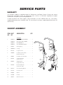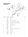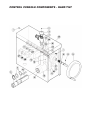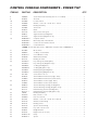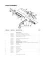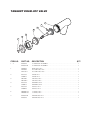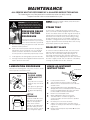
1
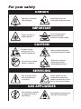
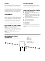
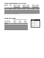
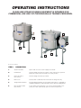
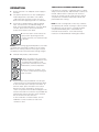
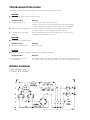
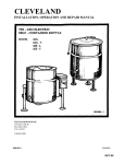
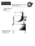
Operators Manual
Installation, Operation & Service
Floor Model Direct Steam Kettles
MODELS:
KDL, KDL-T, KDL-SH, KDL-TSH,
KDP, KDP-T
™
Cleveland
Enodis
1333 East 179th St., Cleveland, Ohio, U.S.A. 44110
Phone: (216) 481-4900 Fax: (216) 481-3782
Visit our web site at www.clevelandrange.com
SE95007 Rev. 6
For your safety
DANGER
Keep clear of pressure
relief discharge.
Keep hands away from
moving parts and pinch points.
IMPORTANT
Do not fill kettle above
recommended level
marked on outside of kettle.
Inspect unit daily for
proper operation.
CAUTION
Surfaces may be
extremely hot! Use
protective equipment.
Wear protective equipment
when discharging hot product.
Do not lean on or place
objects on kettle lip.
Stand clear of product
discharge path when
discharging hot product.
SERVICING
Shut off power at main
fuse disconnect prior
to servicing.
0
Ensure kettle is at room
temperature and pressure
gauge is showing zero or less
prior to removing any fittings.
GAS APPLIANCES
Do not attempt to operate
this appliance during a
power failure.
Keep appliance and area free
and clear of combustibles.
INSTALLATION
GENERAL
KDP SERIES
Installation of the unit must be accomplished by qualified
installation personnel working to all applicable local and
national codes. Improper installation of product could
cause injury or damage.
1.
Position the kettle in its permanent location, and
mark the floor around the circumference of the
base collar or the base plate. Locate the centre of
this circle and mark the floor at this centre point.
This is the point at which the kettle's base plate will
be secured to the floor.
2.
Lay kettle on its side (on a cushioned surface to
prevent scratching), and slide the base collar up
the pedestal, exposing the plate for removal.
3.
Remove the four cap screws securing the base
plate and slide it off the kettle.
4.
Prepare the floor location, for mounting the kettle,
by installing a 3/4" (19mm) stud, cast into the floor,
at the base plate's centre point. Note: a 3/4"
(19mm) lag bolt and floor anchor may be
substituted for a cast-in stud. The anchor is
installed in the floor, and the lag bolt is threaded
down through the base plate, into the anchor, after
completion of step 6.
5.
Thread the four 3/8" (10mm) levelling bolts into
plate from the top, and insert the plate over stud.
6.
Adjust bolts until the plate is level.
7.
Install a nut on the 3/4" (19mm) bolt (or insert a lag
bolt if the alternate fastener method is used) and
secure base plate to the floor.
8.
Check for level "set" of the kettle by placing the
kettle on the base plate with the screw holes
aligned and applying a carpenter's level at the
kettle rim. If the kettle is level, it may be fastened in
place with the four cap screws. If the kettle is not
level, the kettle must be removed from the base,
the plate loosened, and the levelling bolts readjusted until a level installation is attained.
9.
Slide the base collar down to the floor, and draw a
line around the circumference of the pedestal at
the top of the collar, using the top of the collar as a
guide. Slide the collar back up the pedestal.
This unit is built to comply with applicable standards for
manufacturers. Included among those approval
agencies are: UL, NSF, ASME/Ntl.Bd., CSA, ETL, CE,
and others. Many local codes exist, and it is the
responsibility of the owner/installer to comply with these
codes.
INSPECTION
Before uncrating, visually inspect the unit for evidence
of damage during shipping. If damage is noticed, do
not unpack the unit, follow shipping damage
instructions.
SHIPPING DAMAGE
INSTRUCTIONS
If shipping damage to the unit is discovered or
suspected, observe the following guidelines in
preparing a shipping damage claim.
1. Write down a description of the damage or the
reason for suspecting damage as soon as it is
discovered. This will help in filling out the claim
forms later. If possible, take a polaroid picture.
2. As soon as damage is discovered or suspected,
notify the carrier that delivered the shipment.
3. Arrange for the carrier's representative to examine
the damage.
4. Fill out all carrier claims forms and have the
examining carrier sign and date each form.
INSTALLATION
The first installation step is to refer to the Specification
Sheet for detailed clearance requirements, suggested
drain locations and bolting requirements. Next, carefully
cut open and remove the shipping carton. Remove all
supports and fasteners holding unit to the skid.
KDL SERIES
Position the kettle in its permanent location, and level
the kettle by turning the adjustable flanged feet. Once
positioned and levelled, permanently secure the kettle's
flanged feet to the floor using lag bolts and floor
anchors (to be supplied by the installer).
10. Apply a bead of silicone sealer to the circumference
of the pedestal, at the line, and also to the bottom
rim of the collar. Slide the collar down the pedestal
and press it tightly to the floor. The silicone sealer
will create a seal where the collar meets the
pedestal, and where the collar meets the floor.
SERVICE CONNECTIONS
Install service connections as required. Locations and
other data are shown on the Specification Sheet.
STEAM
POTABLE WATER
All steam plumbing to and from the kettle and steam
boiler should be thoroughly cleaned and inspected for
dirt and debris before final connection to the kettle are
made.
The water faucet (optional) with swing spout, requires 1/2
inch O.D. copper tube plumbing for hot or cold water
supplies to the faucet (SPK - cold water connection only,
DPK - hot and cold water connection).
Check the rating plate for the maximum steam pressure
that your kettle is rated for. If the steam supply pressure
exceeds the rated pressure, a pressure reducing valve
is required. The steam inlet is at the right side of the
kettle, as seen from the front.
FINAL INSTALLATION CHECK
1.
Partially fill the kettle with water.
2.
Slowly turn the steam supply valve's knob to the
open position.
CONDENSATE
3.
A steam condensate trap must be plumbed to a drain,
using minimum 1/2" NPT plumbing. The condensate line is
limited to a maximum rise of 10 feet in order for the steam
pressure to adequately force the condensate through the
plumbing. Any higher rise requires a pump.
Release the safety valve, ensuring that the steam
escapes freely. Stay clear of steam exhaust when
releasing the safety valve.
4.
Observe that the water in the kettle comes to a
boil.
5.
Close the steam supply valve.
6.
Drain off the water in the kettle.
If the steam boiler to which this kettle is installed has a
condensate return (closed loop system), a 1/2" steam
strainer, a 1/2" steam trap, and a 1/2" check valve must be
installed on the output (condensate) side of the kettle.
FOR POWER TILT UNITS ONLY
NOTE: Ensure the electrical supply matches the kettle's
requirements as stated on the rating label.
CLEANING
After installation the kettle must be thoroughly cleaned
and sanitized prior to cooking. See CLEANING
INSTRUCTIONS for detailed information and suggested
cleaners.
This kettle is built to comply with CE standards. Many local
codes exist, and it is the responsibility of the owner and
installer to comply with these codes.
NOTE: Maximum voltage for LVD is 440 volts for CE
marked appliances.
RECOMMENDED PIPING
SCHEMATICS
(all service connections shown supplied by others)
1
2
A
B
C
D
E
F
G
Steam In
To Drain or Boiler Condensate Line
Union
Check Valve
Steam Trap
Strainer
Pressure Reducing Valve
Shut Off Valve
Pressure Relief Valve
STEAM REQUIREMENTS FOR KETTLES
Kettle Cap.
U.S. Gal.
Kettle
Dia.
25 psi Steam 265°F
Lbs./Hr.
Hp./Hr.
40 psi Steam 287°F
Lbs./Hr.
Hp./Hr.
80 psi Steam 302°F
Lbs./Hr.
Hp./Hr.
40
26"
100
3
120
4
150
4.5
60
29.5"
150
4.5
190
5.5
230
7.0
80
33"
210
6.0
260
7.5
300
9.0
100
36"
260
7.5
320
9.5
390
11.0
125
40"
320
9.5
400
11.5
470
14.0
150
40"
390
11.0
480
14.0
570
17.0
Steam requirements are maximum per hour.
If more than one unit is on the same line then add the steam usage for each one to reach a total.
STEAM PIPE SIZING
Required pipe length in feet/meters
Steam Required
Lbs./Kg. per hour
200 Ft.
60 Meters
400 Ft.
125 Meters
600 Ft.
185 Meters
100/45 Kg.
3/4"
1"
1 1/4"
200/91 Kg.
1"
1 1/4"
1 1/2"
300/136 Kg.
1"
1 1/4"
1 1/2"
400/182 Kg.
1"
1 1/2"
1 3/4"
500/227 Kg.
1 1/4"
1 1/2"
1 3/4"
700/318 Kg.
1 1/2"
1 3/4"
2"
900/409 Kg.
1 1/2"
1 3/4"
2"
NOTES:
Pipe size in inches.
Less than 50 PSI (3.4
BAR) pressure, increase
pipe size by 1/4".
80 to 100 PSI (5.5 to 6.8
BAR), Decrease pipe
size by 1/4".
OPERATING INSTRUCTIONS
CLEVELAND STEAM COOKING EQUIPMENT IS INTENDED FOR
COMMERCIAL USE ONLY BY PROFESSIONALLY TRAINED PERSONNEL.
1
1
2
5
4
5
General Parts Drawing
ITEM #
DESCRIPTION
1.
Steam Inlet Valve
Opens and closes the steam supply to the kettle.
2.
Hand Wheel
Used for tilting the kettle up or down. Some units have an optional
Power Tilt Control Switch located in the same position.
3.
Power Tilt Switch
(not shown)
Used for tilting the kettle up or down.
4.
Drain Cock
Used to drain condensate from the bottom of tilting units only.
5.
Tangent Draw-Off Valve
Used for draining product or wash water from kettle. It is supplied as
standard equipment on stationary kettles and is optional on tilting kettles.
6.
Pressure Relief Valve
(not shown)
In the unlikely event that there is an excess steam build-up in the
jacket, this valve automatically opens to relieve this pressure.
OPERATION
1.
Ensure that there is an adequate steam supply to
the kettle.
2.
For optimum performance on free-standing floor
model tilting kettles, open drain cock to drain
condensate from the kettle’s jacket, then close
drain cock before applying steam to a cold kettle.
3.
If the kettle is equipped with a tangent draw-off
valve, ensure that it is closed before filling the
kettle. To keep solid food particles out of the drawoff valve, place either a solid or a perforated
strainer in the bottom of the kettle.
4. Turn the steam control valve to the
open position by turning the knob
counter-clockwise, then allow the kettle
to preheat.
NOTE: When cooking egg and milk products, the kettle
should NOT be preheated, as products of this nature
adhere to hot cooking surfaces. These types of foods
should be placed in the kettle before heating is begun.
5.
Fill kettle with product to desired level.
6. When the product has reached the
desired temperature, regulate the heat,
as required, by turning the steam
control valve clockwise for less steam,
and therefore, a lower temperature.
7. When cooking is complete, close
the steam control valve by turning the
knob clockwise.
8.
Power tilt kettles are provided with a rocker-type
center-off switch for raising and lowering the kettle.
To raise the kettle, press the top of the switch. To
lower the kettle, press the bottom of the switch.
Release the switch, allowing it to return to the
center “off” position when the desired degree of tilt
has been reached. Limit switches are provided that
automatically stop the tilt motion at the maximum
limit of movement in either direction.
To raise and lower a manual tilt kettle, turn the
handwheel counter-clockwise to lower and
clockwise to raise.
FOR KETTLE/STEAMER COMBINATIONS:
If the boiler in a steamer is supplying steam to a kettle,
always heat the kettle first. After the kettle contents are
heated, and the boiler's steam pressure returns to
normal, the steamer may be used. Pressure steamer
compartments should be sequentially started, and
preheated before cooking.
NOTE: As with cleaning food soil from any cookware,
art important part of kettle cleaning is to prevent food
from drying on. For this reason, cleaning should be
completed immediately after cooked foods are
removed. Please read the "Care and Cleaning"
instructions for detailed kettle washing procedures.
CLEANING INSTRUCTIONS
CAUTION
SURFACES MAY
BE EXTREMELY HOT!
CARE AND CLEANING
Cooking equipment must be cleaned regularly to
maintain its fast, efficient cooking performance and
to ensure its continued safe, reliable operation. The
best time to clean is shortly after each use (allow
unit to cool to a safe temperature).
CLEANING INSTRUCTIONS
1. Turn unit off.
2. Remove drain screen (if applicable). Thoroughly
wash and rinse the screen either in a sink or a
dishwasher.
3. Prepare a warm water and mild detergent solution in
the unit.
4. Remove food soil using a nylon brush.
5. Loosen food which is stuck by allowing it to soak at
a low temperature setting.
6. Drain unit.
WARNINGS
➩
7. Rinse interior thoroughly.
Do not use detergents or
cleansers that are chloride
based or contain quaternary
salt.
Chloride Cleaners
➩
Do not use a metal bristle
brush or scraper.
8. If the unit is equipped with a Tangent Draw-Off
Valve, clean as follows:
a) Disassemble the draw-off valve first by turning
the valve knob counter-clockwise, then turning
the large hex nut counter-clockwise until the
valve stem is free of the valve body.
b) In a sink, wash and rinse the inside of the valve
body using a nylon brush.
c) Use a nylon brush to clean tangent draw-off tube.
d) Rinse with fresh water.
e) Reassemble the draw-off valve by reversing the
procedure for disassembly. The valve's hex nut
should be hand tight only.
Wire Brush &
➩
Steel wool should never be
used for cleaning the stainless
steel.
9. If the unit is equipped with a Butterfly Valve, clean
as follows:
a) Place valve in open position.
b) Wash using a warm water and mild detergent
solution.
Steel Pads
c) Remove food deposits using a nylon brush.
➩
Unit should never be cleaned
with a high pressure spray
hose.
d) Rinse with fresh water.
e) Leave valve open when unit is not in use.
10. Using mild soapy water and a damp sponge, wash
the exterior, rinse, and dry.
NOTES
High Pressure
Spray Hose
➩
Do not leave water sitting in unit
when not in use.
➩ For more difficult cleaning applications one of the
following can be used: alcohol, baking soda, vinegar,
or a solution of ammonia in water.
➩ Leave the cover off when the kettle is not in use.
Stagnant
Water
➩ For more detailed instructions refer to the Nafem
Stainless Steel Equipment Care and Cleaning manual
(supplied with unit).
STAINLESS STEEL EQUIPMENT CARE AND CLEANING
(Suppied courtesy of Nafem. For more information visit their web site at www.nafem.org)
Contrary to popular belief, stainless steels ARE susceptible to rusting.
4. Treat your water.
Though this is not always practical, softening hard water can do much
to reduce deposits. There are certain filters that can be installed to
remove distasteful and corrosive elements. To insure proper water
treatment, call a treatment specialist.
Corrosion on metals is everywhere. It is recognized quickly on iron and
steel as unsightly yellow/orange rust. Such metals are called “active”
because they actively corrode in a natural environment when their atoms
combine with oxygen to form rust.
Stainless steels are passive metals because they contain other metals, like
chromium, nickel and manganese that stabilize the atoms. 400 series
stainless steels are called ferritic, contain chromium, and are magnetic;
300 series stainless steels are called austenitic, contain chromium and
nickel; and 200 series stainless, also austenitic, contains manganese,
nitrogen and carbon. Austenitic types of stainless are not magnetic, and
generally provide greater resistance to corrosion than ferritic types.
With 12-30 percent chromium, an invisible passive film covers the steel’s
surface acting as a shield against corrosion. As long as the film is intact
and not broken or contaminated, the metal is passive and stain-less. If the
passive film of stainless steel has been broken, equipment starts to
corrode. At its end, it rusts.
5. Keep your food equipment clean.
Use alkaline, alkaline chlorinated or non-chloride cleaners at
recommended strength. Clean frequently to avoid build-up of hard,
stubborn stains. If you boil water in stainless steel equipment,
remember the single most likely cause of damage is chlorides in the
water. Heating cleaners that contain chlorides have a similar effect.
6. Rinse, rinse, rinse.
If chlorinated cleaners are used, rinse and wipe equipment and
supplies dry immediately. The sooner you wipe off standing water,
especially when it contains cleaning agents, the better. After wiping
equipment down, allow it to air dry; oxygen helps maintain the
stainless steel’s passivity film.
Enemies of Stainless Steel
There are three basic things which can break down stainless steel’s
passivity layer and allow corrosion to occur.
7. Never use hydrochloric acid (muriatic acid) on stainless steel.
8. Regularly restore/passivate stainless steel.
1. Mechanical abrasion
2. Deposits and water
Recommended cleaners for specific situations
3. Chlorides
Job
Cleaning Agent
Comments
Mechanical abrasion means those things that will scratch a steel surface.
Steel pads, wire brushes and scrapers are prime examples.
Routine cleaning
Soap, ammonia,
detergent, Medallion
Apply with cloth or sponge
Fingerprints & smears
Arcal 20, Lac-O-Nu
Ecoshine
Provides barrier film
Stubborn stains &
discoloration
Cameo, Talc, Zud,
First Impression
Rub in direction of polish lines
Grease & fatty acids,
blood, burnt-on-foods
Easy-off, De-Grease
It Oven Aid
Excellent removal on all finishes
Grease & oil
Any good
commercial detergent
Apply with sponge or cloth
Restoration/Passivation
Benefit, Super Sheen
Water comes out of the faucet in varying degrees of hardness. Depending
on what part of the country you live in, you may have hard or soft water.
Hard water may leave spots, and when heated leave deposits behind that
if left to sit, will break down the passive layer and rust stainless steel. Other
deposits from food preparation and service must be properly removed.
Chlorides are found nearly everywhere. They are in water, food and table
salt. One of the worst chloride perpetrators can come from household and
industrial cleaners.
So what does all this mean? Don’t Despair!
Here are a few steps that can help prevent stainless steel rust.
1. Use the proper tools.
When cleaning stainless steel products, use non-abrasive tools. Soft
cloths and plastic scouring pads will not harm steel’s passive layer.
Stainless steel pads also can be used but the scrubbing motion must
be in the direction of the manufacturers’ polishing marks.
2. Clean with the polish lines.
Some stainless steel comes with visible polishing lines or “grain.”
When visible lines are present, always scrub in a motion parallel to the
lines. When the grain cannot be seen, play it safe and use a soft cloth
or plastic scouring pad.
Review
1. Stainless steels rust when passivity (film-shield) breaks down as a
result of scrapes, scratches, deposits and chlorides.
2. Stainless steel rust starts with pits and cracks.
3. Use the proper tools. Do not use steel pads, wire brushes or scrapers
to clean stainless steel.
4. Use non-chlorinated cleaners at recommended concentrations. Use
only chloride- free cleaners.
5. Soften your water. Use filters and softeners whenever possible.
6. Wipe off cleaning agent(s) and standing water as soon as possible.
Prolonged contact causes eventual problems.
3. Use alkaline, alkaline chlorinated or non-chloride containing cleaners.
While many traditional cleaners are loaded with chlorides, the industry
is providing an ever-increasing choice of non-chloride cleaners. If you
are not sure of chloride content in the cleaner used, contact your cleaner
supplier. If your present cleaner contains chlorides, ask your supplier if
they have an alternative. Avoid cleaners containing quaternary salts; it
also can attack stainless steel and cause pitting and rusting.
To learn more about chloride-stress corrosion and how to prevent it,
contact the equipment manufacturer or cleaning materials supplier.
Developed by Packer Engineering, Naperville, Ill., an independent testing
laboratory.
SERVICE PARTS
WARRANTY
Our Company supports a worldwide network of Maintenance and Repair Centers. Contact your nearest
Maintenance and Repair Centre for replacement parts, service, or information regarding the proper
maintenance and repair of your cooking equipment
In order to preserve the various agency safety certification (UL, NSF, ASME/Ntl. Bd., etc.), only factorysupplied replacement parts should be used. The use of other than factory supplied replacement parts will
void warranty.
FAUCET ASSEMBLY
ITEM PART
NO. NO.
DESCRIPTION
QTY.
3/4" Spouts
1.
KE50825-2
KDL-60/80/100-T, KDP-60/80-T . . . . . . . . .1
KE50825-3
KDL-25/40-T, KDP-25/30/40-T . . . . . . . . . .1
KE50825-7
KDL-40/60/80-TSH, . . . . . . . . . . . . . . . . . .1
KE50825-5
ALL STATIONARY KETTLES . . . . . . . . . . .1
2.
FA95022
Retaining Ring . . . . . . . . . . . . . . . . . . . . . .1
3.
FA05002-19
"O" Ring . . . . . . . . . . . . . . . . . . . . . . . . . . .1
4.
KE51736
Long Faucet Nut . . . . . . . . . . . . . . . . . . . .1
5.
SE50020
Hot Water Stem Assembly . . . . . . . . . . . . .1
(Double Pantry only)
1
2
1
3
4
2
6.
SE50021
5
3
6
4
6
Cold Water Stem Assembly . . . . . . . . . . . .1
10
7
7.
KE51401
Single Pantry Body . . . . . . . . . . . . . . . . . .1
(c/w Item No. 6)
11
9
8
12
13
8.
9.
KE50335
KE51403
Adapter Washer . . . . . . . . . . . . . . . . . . . . .1
(Single Pantry only)
10
Double Pantry Body . . . . . . . . . . . . . . . . . .1
(c/w Item No. 5&6)
11
12
13
10.
KE54159
Faucet Mounting Bracket . . . . . . . . . . . . . .1
11.
FA11258
Hex Cap Screw . . . . . . . . . . . . . . . . . . . . .2
12.
FA30505
Washer . . . . . . . . . . . . . . . . . . . . . . . . . . . .2
13.
FA21008
Hex Nut . . . . . . . . . . . . . . . . . . . . . . . . . . .2
14.
SE50447
Washer Horseshoe . . . . . . . . . . . . . . . . . . .1
14
STEAM CONTROL
ASSEMBLIES
ITEM NO.
PART NO.
DESCRIPTION
1.
2.
3.
4.
5.
6.
KE51892
KE51888
FA11501
SE00028
KE02055-3
KE54941-2
KE54941-15
KE54941-11
KE54941-12
KE52700
FA00596
FI05078
KE52701
KE52702
FA05202-16
KE50676
KE00353
KE00352
KE51886
KE51711
KE51571-1
FA95081-3
FA95007-1
FA05002-6
FI00352
KE50675
Retaining ring . . . . . . . . . . . . . . . . . . . . . . . . . . . . . . . . . . . . . . . . . . . . . . . . . . .1
Washer . . . . . . . . . . . . . . . . . . . . . . . . . . . . . . . . . . . . . . . . . . . . . . . . . . . . . . . .1
Valve knob screw . . . . . . . . . . . . . . . . . . . . . . . . . . . . . . . . . . . . . . . . . . . . . . . .1
Valve knob assembly (includes item 1, 2, 3) . . . . . . . . . . . . . . . . . . . . . . . . . . .1
3/4" Chrome steam inlet valve . . . . . . . . . . . . . . . . . . . . . . . . . . . . . . . . . . . . . . .1
3/4" Pressure relief valve, 50 psi, up to 100 gallon . . . . . . . . . . . . . . . . . . . . . . .1
3/4" Pressure relief valve, 100 psi, up to 100 gallon . . . . . . . . . . . . . . . . . . . . . .1
3/4" Pressure relief valve, 35 psi, 125 gallon and up . . . . . . . . . . . . . . . . . . . . .1
3/4" Pressure relief valve, 100 psi, 125 gallon and up . . . . . . . . . . . . . . . . . . . .1
1/2" Check valve . . . . . . . . . . . . . . . . . . . . . . . . . . . . . . . . . . . . . . . . . . . . . . . . .1
Nipple 1/2" NPT x 1 1/2" long . . . . . . . . . . . . . . . . . . . . . . . . . . . . . . . . . . . . . . .2
90° Elbow (chrome plated) . . . . . . . . . . . . . . . . . . . . . . . . . . . . . . . . . . . . . . . . .2
1/2" Steam trap . . . . . . . . . . . . . . . . . . . . . . . . . . . . . . . . . . . . . . . . . . . . . . . . . .1
1/2" Strainer . . . . . . . . . . . . . . . . . . . . . . . . . . . . . . . . . . . . . . . . . . . . . . . . . . . . .1
"O" Ring . . . . . . . . . . . . . . . . . . . . . . . . . . . . . . . . . . . . . . . . . . . . . . . . . . . . . . . .1
Connector . . . . . . . . . . . . . . . . . . . . . . . . . . . . . . . . . . . . . . . . . . . . . . . . . . . . . .1
Trunnion bearing, spring assist cover (includes items 15, 17 & 18) . . . . . . . . .1
Trunnion bearing, no cover (includes items 15, 17 & 18)
Grease nipple . . . . . . . . . . . . . . . . . . . . . . . . . . . . . . . . . . . . . . . . . . . . . . . . . . .2
Roller Bearing . . . . . . . . . . . . . . . . . . . . . . . . . . . . . . . . . . . . . . . . . . . . . . . . . . .2
Spherical washer . . . . . . . . . . . . . . . . . . . . . . . . . . . . . . . . . . . . . . . . . . . . . . . . .1
Bolt, 5/16"-18 x 1/2” . . . . . . . . . . . . . . . . . . . . . . . . . . . . . . . . . . . . . . . . . . . . . . .1
Retaining ring . . . . . . . . . . . . . . . . . . . . . . . . . . . . . . . . . . . . . . . . . . . . . . . . . . .1
"O" Ring . . . . . . . . . . . . . . . . . . . . . . . . . . . . . . . . . . . . . . . . . . . . . . . . . . . . . . . .2
Reducer bushing 1/2 x 3/8 . . . . . . . . . . . . . . . . . . . . . . . . . . . . . . . . . . . . . . . . .1
Drain cock . . . . . . . . . . . . . . . . . . . . . . . . . . . . . . . . . . . . . . . . . . . . . . . . . . . . . .1
8.
9.
10.
11.
12.
14.
15.
16.
17.
18.
19.
20.
21.
22.
23.
24.
QTY.
CONTROL CONSOLE COMPONENTS - HAND TILT
ITEM NO.
PART NO.
DESCRIPTION
1.
FA11134
Screw, #1-24 . . . . . . . . . . . . . . . . . . . . . . . . . . . . . . . . . . . . . . . . . . . . . . . . . . . .2
2.
FA11501
Screw . . . . . . . . . . . . . . . . . . . . . . . . . . . . . . . . . . . . . . . . . . . . . . . . . . . . . . . . . .1
3.
SE00028
Valve Knob (Item no. 2 included) . . . . . . . . . . . . . . . . . . . . . . . . . . . . . . . . . . . .1
4.
KE00350
Brass Steam Inlet Valve & Stem, 3/4" (Item no. 2 & 3 not included) . . . . . . . . .1
SE50441-2
Replacement Stem (without valve) . . . . . . . . . . . . . . . . . . . . . . . . . . . . . . . . . . .1
5.
FA95008
Lock Nut, 3/4-16 . . . . . . . . . . . . . . . . . . . . . . . . . . . . . . . . . . . . . . . . . . . . . . . . .2
6.
FA30088
Washer, tilt shaft . . . . . . . . . . . . . . . . . . . . . . . . . . . . . . . . . . . . . . . . . . . . . . . . .1
7.
SE00036
Thrust Bearing Assembly (Item no. 27, 28, & 29 included) . . . . . . . . . . . . . . . .2
8.
FA95007-1
Retaining Ring (25-60 gallon) . . . . . . . . . . . . . . . . . . . . . . . . . . . . . . . . . . . . . . .1
FA95007-4
Retaining Ring (80 gallon & up) . . . . . . . . . . . . . . . . . . . . . . . . . . . . . . . . . . . . .1
FA05002-6
"O" Ring (25-60 gallon) . . . . . . . . . . . . . . . . . . . . . . . . . . . . . . . . . . . . . . . . . . . .2
FA05002-27
"O" Ring (80 gallon & up) . . . . . . . . . . . . . . . . . . . . . . . . . . . . . . . . . . . . . . . . . .2
FA95055-4
Key, worm gear (25-60 gallon) . . . . . . . . . . . . . . . . . . . . . . . . . . . . . . . . . . . . . .1
FA95055-7
Key, worm gear (80 gallon & up) . . . . . . . . . . . . . . . . . . . . . . . . . . . . . . . . . . . .1
KE51711
Roller Bearing, trunnion (25-60 gallon) . . . . . . . . . . . . . . . . . . . . . . . . . . . . . . . .2
KE517111
Roller Bearing, trunnion (80 gallon & up) . . . . . . . . . . . . . . . . . . . . . . . . . . . . . .2
12.
FA95005
Tension Pin . . . . . . . . . . . . . . . . . . . . . . . . . . . . . . . . . . . . . . . . . . . . . . . . . . . . .1
13.
KE503751
Tilt Shaft . . . . . . . . . . . . . . . . . . . . . . . . . . . . . . . . . . . . . . . . . . . . . . . . . . . . . . . .1
14.
FA19505
Allen Screw, hand wheel . . . . . . . . . . . . . . . . . . . . . . . . . . . . . . . . . . . . . . . . . . .1
15.
KE00508
Hand Wheel . . . . . . . . . . . . . . . . . . . . . . . . . . . . . . . . . . . . . . . . . . . . . . . . . . . . .1
16.
KE00164-1
Trunnion Bearing Housing (25-60 gallon) . . . . . . . . . . . . . . . . . . . . . . . . . . . . . .1
KE00164-2
Trunnion Bearing Housing (80 gallon & up) . . . . . . . . . . . . . . . . . . . . . . . . . . . .1
KE00151
Segment Gear (25-60 gallon) . . . . . . . . . . . . . . . . . . . . . . . . . . . . . . . . . . . . . . .1
KE52833
Segment Gear (80 gallon & up) . . . . . . . . . . . . . . . . . . . . . . . . . . . . . . . . . . . . .1
18.
FA19186
Allen Screw, worm gear . . . . . . . . . . . . . . . . . . . . . . . . . . . . . . . . . . . . . . . . . . .1
19.
KE50315
Worm . . . . . . . . . . . . . . . . . . . . . . . . . . . . . . . . . . . . . . . . . . . . . . . . . . . . . . . . . .1
20.
KE55057-6
Gear Box Lid (25-60 gallon) . . . . . . . . . . . . . . . . . . . . . . . . . . . . . . . . . . . . . . . .1
KE55057-5
Gear Box Lid (80 gallon & up) . . . . . . . . . . . . . . . . . . . . . . . . . . . . . . . . . . . . . .1
21.
KE51731
Bearing, tilt shaft . . . . . . . . . . . . . . . . . . . . . . . . . . . . . . . . . . . . . . . . . . . . . . . . .1
22-24
SE00036
Assembly . . . . . . . . . . . . . . . . . . . . . . . . . . . . . . . . . . . . . . . . . . . . . . . . . . . . . . .1
22.
KE51891
Washer, 1 1/2" O.D. x 13/16" I.D. x .037" W. . . . . . . . . . . . . . . . . . . . . . . . . . . . .1
23.
T40226
Bearing Assembly . . . . . . . . . . . . . . . . . . . . . . . . . . . . . . . . . . . . . . . . . . . . . . . .1
24.
FA20029
Hex Nut, 5/16-24 . . . . . . . . . . . . . . . . . . . . . . . . . . . . . . . . . . . . . . . . . . . . . . . . .1
25.
FA10623
Bolt, 5/16-24 x 1 1/2" . . . . . . . . . . . . . . . . . . . . . . . . . . . . . . . . . . . . . . . . . . . . . .1
27.
KE52192
Washer, thrust bearing . . . . . . . . . . . . . . . . . . . . . . . . . . . . . . . . . . . . . . . . . . . .2
28.
KE52191
Bearing, thrust . . . . . . . . . . . . . . . . . . . . . . . . . . . . . . . . . . . . . . . . . . . . . . . . . . .1
29.
KE52193
Spacer, thrust bearing . . . . . . . . . . . . . . . . . . . . . . . . . . . . . . . . . . . . . . . . . . . . .1
30.
KE50426-4
Spacer . . . . . . . . . . . . . . . . . . . . . . . . . . . . . . . . . . . . . . . . . . . . . . . . . . . . . . . . .1
9.
10.
11.
17.
QTY.
CONTROL CONSOLE COMPONENTS - HAND TILT
CONTROL CONSOLE COMPONENTS POWER TILT
43
45
44
ITEM NO.
PART NO.
DESCRIPTION
QTY.
1.
KE55057-10
Gear Box Lid (25-60 gallon) . . . . . . . . . . . . . . . . . . . . . . . . . . . . . . . . . . . . . . . .1
KE55057-3
Gear Box Lid (80 gallon & up) . . . . . . . . . . . . . . . . . . . . . . . . . . . . . . . . . . . . . .1
2.
FA11134
Screw, 10-24 x 3/8" SS . . . . . . . . . . . . . . . . . . . . . . . . . . . . . . . . . . . . . . . . . . . .1
3.
KE52832-1
Motor . . . . . . . . . . . . . . . . . . . . . . . . . . . . . . . . . . . . . . . . . . . . . . . . . . . . . . . . . .1
4.
KE50583
Buna-N Insert . . . . . . . . . . . . . . . . . . . . . . . . . . . . . . . . . . . . . . . . . . . . . . . . . . .1
5.
KE50582
Coupling . . . . . . . . . . . . . . . . . . . . . . . . . . . . . . . . . . . . . . . . . . . . . . . . . . . . . . .2
6.
7.
KE00350
Brass Steam Inlet Valve & Stem, 3/4" (Item no. 7 & 8 not included) . . . . . . . . .1
SE50441-2
Replacement Stem (without valve) . . . . . . . . . . . . . . . . . . . . . . . . . . . . . . . . . . .1
FA11501
Screw . . . . . . . . . . . . . . . . . . . . . . . . . . . . . . . . . . . . . . . . . . . . . . . . . . . . . . . . . .1
CONTROL CONSOLE COMPONENTS - POWER TILT
ITEM NO.
PART NO.
DESCRIPTION
8.
9.
10.
12.
13.
14.
15.
16.
17.
SE00028
KE50441
FA95008
FA30088
SE00036
FA95005
KE50315
FA19186
KE00151
KE52833
KE003209-11
Steam Inlet Knob Assembly (Item no. 7 included) . . . . . . . . . . . . . . . . . . . . . . .1
Tilt Shaft . . . . . . . . . . . . . . . . . . . . . . . . . . . . . . . . . . . . . . . . . . . . . . . . . . . . . . . .1
Locknut, 3/4-16 . . . . . . . . . . . . . . . . . . . . . . . . . . . . . . . . . . . . . . . . . . . . . . . . . .2
Washer, 1 1/2" O.D. x 13/16" I.D. x .125 W. . . . . . . . . . . . . . . . . . . . . . . . . . . . .1
Bearing Assembly . . . . . . . . . . . . . . . . . . . . . . . . . . . . . . . . . . . . . . . . . . . . . . . .2
Tension Pin . . . . . . . . . . . . . . . . . . . . . . . . . . . . . . . . . . . . . . . . . . . . . . . . . . . . .1
Worm . . . . . . . . . . . . . . . . . . . . . . . . . . . . . . . . . . . . . . . . . . . . . . . . . . . . . . . . . .1
Allen Screw, worm gear . . . . . . . . . . . . . . . . . . . . . . . . . . . . . . . . . . . . . . . . . . .1
Segment Gear (25-60 gallon) . . . . . . . . . . . . . . . . . . . . . . . . . . . . . . . . . . . . . . .1
Segment Gear (80 gallon & up) . . . . . . . . . . . . . . . . . . . . . . . . . . . . . . . . . . . . .1
Complete Switch . . . . . . . . . . . . . . . . . . . . . . . . . . . . . . . . . . . . . . . . . . . . . . . . .1
18.
QTY.
KE603208-4
Momentary Switch Activator*** . . . . . . . . . . . . . . . . . . . . . . . . . . . . . . . . . . . . . .1
KE603208-7
Contact Section Holder, Latch*** . . . . . . . . . . . . . . . . . . . . . . . . . . . . . . . . . . . .1
KE603208-9
Contact Block*** . . . . . . . . . . . . . . . . . . . . . . . . . . . . . . . . . . . . . . . . . . . . . . . . . 4
***NOTE: for units built prior to Dec. 2006 order Complete Switch KE003209-11
21.
22.
23.
24.
25.
26.
27.
28.
29.
31.
32.
33.
34.
35.
36.
37.
38.
39.
40.
41.
42.
43.
44.
45.
46.
KE51007
FA00012
KE50579-1
KE50580
KE51731
FA95055-4
FA95055-7
FA05002-6
FA05002-27
FA95007-1
FA95007-4
FA11092
KE50376
SK50054
KE50377
SK50055
KE00164
KE01347
KE51711
KE51711-1
T40226
FA10623
FA20029
KE51891
KE52192
KE52191
KE52193
FA95037
KE50581
KE54535
KE50753-10
KE50426-4
Micro Switch . . . . . . . . . . . . . . . . . . . . . . . . . . . . . . . . . . . . . . . . . . . . . . . . . . . .2
"O" Ring, circuit breaker . . . . . . . . . . . . . . . . . . . . . . . . . . . . . . . . . . . . . . . . . . .1
Circuit Breaker, 1 amp. . . . . . . . . . . . . . . . . . . . . . . . . . . . . . . . . . . . . . . . . . . . .1
Water Resistant Boot . . . . . . . . . . . . . . . . . . . . . . . . . . . . . . . . . . . . . . . . . . . . . .1
Bearing, tilt shaft . . . . . . . . . . . . . . . . . . . . . . . . . . . . . . . . . . . . . . . . . . . . . . . . .1
Key, worm gear (25-60 gallon) . . . . . . . . . . . . . . . . . . . . . . . . . . . . . . . . . . . . . .1
Key, worm gear (80 gallon & up) . . . . . . . . . . . . . . . . . . . . . . . . . . . . . . . . . . . .1
"O" Ring (25-60 gallon) . . . . . . . . . . . . . . . . . . . . . . . . . . . . . . . . . . . . . . . . . . . .4
"O" Ring (80 gallon & up) . . . . . . . . . . . . . . . . . . . . . . . . . . . . . . . . . . . . . . . . . .4
Retaining Ring (25-60 gallon) . . . . . . . . . . . . . . . . . . . . . . . . . . . . . . . . . . . . . . .1
Retaining Ring (80 gallon & up) . . . . . . . . . . . . . . . . . . . . . . . . . . . . . . . . . . . . .1
Screw, 8-32 x 1/2" SS . . . . . . . . . . . . . . . . . . . . . . . . . . . . . . . . . . . . . . . . . . . . .4
Terminal Block End Section (large, white) . . . . . . . . . . . . . . . . . . . . . . . . . . . . .1
Terminal Block End Section (small, black) . . . . . . . . . . . . . . . . . . . . . . . . . . . . .1
Terminal Block Section (large, white) . . . . . . . . . . . . . . . . . . . . . . . . . . . . . . . . .3
Terminal Block Section (small, black) . . . . . . . . . . . . . . . . . . . . . . . . . . . . . . . . .3
Trunnion Bearing Housing (25-60 gallon) . . . . . . . . . . . . . . . . . . . . . . . . . . . . . .1
Trunnion Bearing Housing (80 gallon & up) . . . . . . . . . . . . . . . . . . . . . . . . . . . .1
Roller Bearing, trunnion (25-60 gallon) . . . . . . . . . . . . . . . . . . . . . . . . . . . . . . . .2
Roller Bearing, trunnion (80 gallon & up) . . . . . . . . . . . . . . . . . . . . . . . . . . . . . .2
Bearing Assembly . . . . . . . . . . . . . . . . . . . . . . . . . . . . . . . . . . . . . . . . . . . . . . . .1
Bolt, 5/16-24 x 1 1/2" . . . . . . . . . . . . . . . . . . . . . . . . . . . . . . . . . . . . . . . . . . . . . .1
Nut, hex, 5/16-24 . . . . . . . . . . . . . . . . . . . . . . . . . . . . . . . . . . . . . . . . . . . . . . . . .1
Washer, 1 1/2" O.D. x 13/16" I.D. x .037" W. . . . . . . . . . . . . . . . . . . . . . . . . . . .2
Washer, thrust bearing . . . . . . . . . . . . . . . . . . . . . . . . . . . . . . . . . . . . . . . . . . . .4
Bearing, thrust . . . . . . . . . . . . . . . . . . . . . . . . . . . . . . . . . . . . . . . . . . . . . . . . . . .2
Spacer, thrust bearing . . . . . . . . . . . . . . . . . . . . . . . . . . . . . . . . . . . . . . . . . . . . .2
Key, 3/16" x 3/16" x 3/4" . . . . . . . . . . . . . . . . . . . . . . . . . . . . . . . . . . . . . . . . . . .1
Bridge Rectifier . . . . . . . . . . . . . . . . . . . . . . . . . . . . . . . . . . . . . . . . . . . . . . . . . .1
Edge Connector (11 pin) . . . . . . . . . . . . . . . . . . . . . . . . . . . . . . . . . . . . . . . . . .2
Relay . . . . . . . . . . . . . . . . . . . . . . . . . . . . . . . . . . . . . . . . . . . . . . . . . . . . . . . . . .2
Spacer . . . . . . . . . . . . . . . . . . . . . . . . . . . . . . . . . . . . . . . . . . . . . . . . . . . . . . . . .1
HINGE ASSEMBLY
9
4
7
11
8
6
10
1
9
5
12
ITEM NO.
PART NO.
DESCRIPTION
13
2
3
QTY.
Hinge Assembly
1. - 11
KE50597-1
25 - 40 Gallon, 20 Gallon Full Jacketed . . . . . . . . . . . . . . . . . . . . . . . . . . . . . . .1
KE50597-2
60 - 80 Gallon, 30 - 40 Gallon Full Jacketed . . . . . . . . . . . . . . . . . . . . . . . . . . .1
KE50597-3
100 - 150 Gallon, 60 - 100 Gallon Full Jacketed . . . . . . . . . . . . . . . . . . . . . . . .1
KE50597-4
KDM-60, KDM-60-T, Cook Tank . . . . . . . . . . . . . . . . . . . . . . . . . . . . . . . . . . . . .1
KE50597-5
KDL-200, KDL-250, KDL-150-F, KDL-250-F . . . . . . . . . . . . . . . . . . . . . . . . . . . .1
1.
KE50822
Hinge Base . . . . . . . . . . . . . . . . . . . . . . . . . . . . . . . . . . . . . . . . . . . . . . . . . . . . .1
2.
KE51217
Hinge Cylinder . . . . . . . . . . . . . . . . . . . . . . . . . . . . . . . . . . . . . . . . . . . . . . . . . .1
3.
KE50121-2
Hinge Spring Light - for KE50597-2 . . . . . . . . . . . . . . . . . . . . . . . . . . . . . . . . .1
KE50121-1
Hinge Spring Heavy - for KE50597-1, KE50597-3, KE50597-4, KE50597-5, . .1
4.
KE50823-1
Hinge Pin . . . . . . . . . . . . . . . . . . . . . . . . . . . . . . . . . . . . . . . . . . . . . . . . . . . . . . .1
5.
KE50824
Hinge Bearing . . . . . . . . . . . . . . . . . . . . . . . . . . . . . . . . . . . . . . . . . . . . . . . . . . .1
6.
KE50819-1
Hinge End Piece . . . . . . . . . . . . . . . . . . . . . . . . . . . . . . . . . . . . . . . . . . . . . . . . .1
7.
KE50820
Hinge Insert . . . . . . . . . . . . . . . . . . . . . . . . . . . . . . . . . . . . . . . . . . . . . . . . . . . . .1
8.
KE50819
Hinge End Piece . . . . . . . . . . . . . . . . . . . . . . . . . . . . . . . . . . . . . . . . . . . . . . . . .1
9.
FA11284
Screw, Socket Head . . . . . . . . . . . . . . . . . . . . . . . . . . . . . . . . . . . . . . . . . . . . . .4
10.
FA11507
Cutting Screw,
11.
SK50418
Plug Button . . . . . . . . . . . . . . . . . . . . . . . . . . . . . . . . . . . . . . . . . . . . . . . . . . . . .1
12.
KE50151-2
Knob . . . . . . . . . . . . . . . . . . . . . . . . . . . . . . . . . . . . . . . . . . . . . . . . . . . . . . . . . .1
13.
. . . . . . . . . . . . . . . . . . . . . . . . . . . . . . . . . . . . . . . . . . . . . . . . . .2
Cover Handle (specify model) . . . . . . . . . . . . . . . . . . . . . . . . . . . . . . . . . . . . . .1
TANGENT DRAW-OFF VALVE
7
6
5
4
3
2
1
ITEM NO.
PART NO.
DESCRIPTION
QTY.
1. - 7.
KE50973
KE50972-B
2” DRAW-OFF ASSEMBLY . . . . . . . . . . . . . . . . . . . . . . . . . . . . . . . . . . . . . . . . .1
3” DRAW-OFF ASSEMBLY . . . . . . . . . . . . . . . . . . . . . . . . . . . . . . . . . . . . . . . . .1
1.
FA95049
FA21050
FA21501-1
WING NUT, TD-2 . . . . . . . . . . . . . . . . . . . . . . . . . . . . . . . . . . . . . . . . . . . . . . . . .1
ACCORN NUT, TD-2 . . . . . . . . . . . . . . . . . . . . . . . . . . . . . . . . . . . . . . . . . . . . . .1
ACCORN NUT, TD-3 . . . . . . . . . . . . . . . . . . . . . . . . . . . . . . . . . . . . . . . . . . . . . .1
2.
KE52755
SE50018
KNOB, TD-2 . . . . . . . . . . . . . . . . . . . . . . . . . . . . . . . . . . . . . . . . . . . . . . . . . . . .1
KNOB, TD-3 . . . . . . . . . . . . . . . . . . . . . . . . . . . . . . . . . . . . . . . . . . . . . . . . . . . .1
3.
FI05180-1
FI05180-2
HEX NUT, TD-2 . . . . . . . . . . . . . . . . . . . . . . . . . . . . . . . . . . . . . . . . . . . . . . . . . .1
HEX NUT, TD-3 . . . . . . . . . . . . . . . . . . . . . . . . . . . . . . . . . . . . . . . . . . . . . . . . . .1
4.
KE52753
SE50013
RETAINER, TD-2 . . . . . . . . . . . . . . . . . . . . . . . . . . . . . . . . . . . . . . . . . . . . . . . . .1
RETAINER, TD-3 . . . . . . . . . . . . . . . . . . . . . . . . . . . . . . . . . . . . . . . . . . . . . . . . .1
5.
KE52752
SE50010
PISTON, TD-2 . . . . . . . . . . . . . . . . . . . . . . . . . . . . . . . . . . . . . . . . . . . . . . . . . . .1
PISTON, TD-3 . . . . . . . . . . . . . . . . . . . . . . . . . . . . . . . . . . . . . . . . . . . . . . . . . . .1
6.
FA05002-24
FA05002-38
"O" RING, TD-2 . . . . . . . . . . . . . . . . . . . . . . . . . . . . . . . . . . . . . . . . . . . . . . . . . .1
"O" RING, TD-3 . . . . . . . . . . . . . . . . . . . . . . . . . . . . . . . . . . . . . . . . . . . . . . . . . .1
7.
KE50972-B
KE50973
VALVE BODY, TD-2 . . . . . . . . . . . . . . . . . . . . . . . . . . . . . . . . . . . . . . . . . . . . . . .1
VALVE BODY, TD-3 . . . . . . . . . . . . . . . . . . . . . . . . . . . . . . . . . . . . . . . . . . . . . .1
MAINTENANCE
ALL SERVICE MUST BE PERFORMED BY A QUALIFIED SERVICE TECHNICIAN.
This kettle requires very little preventative maintenance other than daily cleaning.
The pressure relief valve must be tested twice a year.
DANGER: Pressure relief valve will
exhaust high temperature steam. Contact
with skin could result in serious burns. Keep
face, hands and body clear of discharge.
PRESSURE RELIEF
VALVE TESTING
PROCEDURE
The pressure relief valve must be
checked at least twice a year as part
of the normal maintenance performed.
1.
With the kettle empty, fully open the steam valve and
allow the kettle to preheat.
2.
Stand to the side of the pressure relief valve discharge tube
and pull valve open for a maximum of one second. Repeat
test three to four times. Each time the mechanism should
move freely and be accompanied by a rapid escape of steam.
⇒
If valve appears to be sticking replace pressure relief valve.
⇒
If foreign material is discharged then drain kettle and
replace pressure relief valve.
LUBRICATION PROCEDURE
Lubricate the following parts every three months to insure
smooth operation and reduce wear.
TRUNNION
HOUSING, WORM
SCREW AND TILT
GEAR
Adjusting
Screw
Worm
Screw and
Tilt
Gear
Cross
Bar
These parts are accessed
through the top cover of the
console.
Apply grease to gear teeth.
Check for excessive play
and adjust with adjusting
screw located on top of cross bar.
Trunnion Housing
Grease Nipple
KETTLE
TRUNNIONS
On the left hand side of the
kettle there are two grease
nipples on the top back
portion of the trunnion
housing. On the right hand
side of the kettle you must
remove the console cover to
access the grease nipple.
WARNING: Improper refilling of kettle jacket will result in
irreversible damage to unit.
STEAM TRAP
To remove line condensate that forms inside the steam
jacket, each kettle should be equipped with a steam trap in
the line of the kettle outlet to the drain. A good steam trap at
startup releases air and wet steam into the drain line for a
few minutes, then holds the steam jacket. During cooking,
the trap periodically releases accumulated condensate. If
the kettle's cooking performance becomes inadequate after
long use, replacement of the steam trap with a new one may
restore kettle operation to peak efficiency.
DRAW-OFF VALVE
To correct a leak at the draw-off valve, the source of the
leak must first be determined, Leaks from around the
valve stem are corrected by simply replacing the “O”
ring. Faulty seating of the valve stem disc against the
valve body may cause dripping from the valve even when
the valve is tightly closed. This can often be corrected by
cleaning any residue from the disc and seat.
HINGE ADJUSTMENT
INSTRUCTIONS
1.
2.
3.
4.
5.
6.
7.
8.
9.
10.
3/8" Allen wrench
Insert 3/8" Allen wrench.
Turn clockwise to relieve tension on spring.
While tension is released remove one of the two
slotted screws.
To prevent Allen wrench from springing back
abruptly while the second slotted screw is removed,
insert a pin (approximately 1/8") in the hole where
the first slotted screw was removed from.
Remove second slotted screw.
While holding Allen wrench remove pin.
Turn Allen wrench clockwise to tighten or
counter-clockwise to loosen tension to produce
desired effect.
Re-insert pin in one of the two holes.
Tighten one slotted screw in the other hole (it
may be necessary to turn Allen wrench slightly to
align holes).
Remove pin and repeat step number 9. for other
slotted screw.
TROUBLESHOOTING GUIDE
This section contains information intended for use by Authorized Service Personnel only.
PROBLEM
A/ Kettle heats too slowly or does not come to a boil.
Probable Cause
1. Inadequate steam flow.
Remedy
Check for correct steam using chart below.
If kettle is connected to a steamer and powered by a generator the units
should be operated sequentially (kettle boiling first, then start steamer).
2. Steam trap not operating properly. The trap should open periodically to dump condensate, then close.
If it does not open or close it should be cleaned or replaced.
3. Food batches are not always
the same.
When checking make certain that the original state (ie. fresh or frozen)
and quantity of food product is the same.
PROBLEM
B/ The trunnion housing leaks steam.
Probable Cause
1. Trunnion "O" rings are worn.
Remedy
Replace "O" rings
PROBLEM
B/ The steam trap makes a banging noise when steam applied to cold kettle.
Probable Cause
1. Kettle condensate has not
been drained.
WIRING DIAGRAM
Power Tilt Units Only
115 Volts, 1PH, 50/60HZ
Remedy
On all tilting models the condensate should be drained from the cold kettle. This is
done before steam is applied using the drain cock valve on the bottom of the kettle.