1
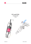
pHX / ReX
pH- / Redox
Sensor
2006-08-08
MANE08/06 Ver 2.20
TABLE OF CONTENTS
1.
2.
3.
4.
5.
6.
Introduction ................................................................................................ 3
A few words about this manual ................................................................ 3
Design ......................................................................................................... 3
Measuring principle ................................................................................... 3
Unpacking the Sensor ............................................................................... 4
Installing the Sensor.................................................................................. 5
Connections..................................................................................................................... 6
Installation hints .............................................................................................................. 6
Starting Up ...................................................................................................................... 6
7. Removing the sensor................................................................................. 6
8. Mounting the electrode.............................................................................. 7
9. Cleaning...................................................................................................... 8
Mounting plate for cleaning solenoid valves ................................................................. 8
10. Maintenance ............................................................................................... 9
Error messages ................................................................................................................ 9
Broken Electrode............................................................................................................. 9
Incorrect Measurements.................................................................................................. 9
11. Sensor display ......................................................................................... 10
12. Menu for Sensors..................................................................................... 11
Menu for pHX ............................................................................................................... 11
Menu for ReX ............................................................................................................... 13
13. Calibration ................................................................................................ 15
Calibrating pH............................................................................................................... 15
Adjusting ORP .............................................................................................................. 16
14. Scaling ...................................................................................................... 16
15. Technical data pHX / ReX ........................................................................ 17
16. Dimensions............................................................................................... 19
Appendix 1, Optional slide rail holder .......................................................... 20
Appendix 2, pH as a function of mV ............................................................. 21
Appendix 3, pH temperature dependency.................................................... 22
Appendix 4, Support information.................................................................. 23
Appendix 5, Setup information ..................................................................... 24
-2-
1. Introduction
pHX / ReX are used to measure pH or Redox potential in water and wastewater
treatment plants and other industrial applications.
2. A few words about this manual
This manual details installation procedures and operational features of the Cerlic pH and
Redox sensors. Menu navigation and technical data for the BB2 control box can be
found in the BB2 service manual.
3. Design
The pHX / ReX sensors are manufactured in SIS2343 (316SS) stainless steel and PVC.
The sensors are mounted using PVC clamps. An adjustable stainless steel slide rail
holder is available as an option as well as equipment for automatic cleaning.
The sensor has a fixed, shielded 10 m (33’) cable used for signal transmission between
the sensor and the BB2 control box.
4. Measuring principle
pH is normally measured with an electrode where pH is expressed as a function of
voltage. Today's electrodes often contain both a measuring electrode and a reference
electrode, which in combination provide a voltage in linear proportion to the pH value.
Electrodes internally combined with a reference and measuring cell are divided into two
categories: gel electrodes and refillable electrodes. The gel electrode is the simpler and
less expensive type. There are a number of different types of refillable electrodes for
different applications, each with different internal solutions that are to be added at
regular intervals. Cerlic provides a gel-filled glass electrode.
The temperature of the calibration buffer and the media to be measured can be entered
in BB2 to compensate for the temperature dependence of the electrode. All settings are
made in the central unit BB2 using a self-instructing menu controlled by just three keys.
The output signal is frozen when you switch to menu mode so that the output signal will
not change during procedures such a re-calibration.
The BB2 has two 4-20 mA outputs, and relay outputs for alarm and cleaning of the
electrode.
The current pH/mV is continuously displayed in a window, maximum, minimum and
average values for the last 24 hours can be obtained by pressing two buttons.
-3-
5. Unpacking the Sensor
The unit has been tested and approved before delivery from the supplier. Please check
to confirm that no visible damages occurred during shipment.
Damages
If damages occurred during shipment, immediately contact UPS or other truck line as
well as your Cerlic representative. The shipment can be returned only after contact has
been made with Cerlic.
Packaging
The original packaging is designed to protect the equipment and should be used for
storage or if the goods must be returned.
Content
Please check that the content corresponds to your order and packing list.
Every shipment should include:
•
Sensor w/ 10 m (33ft) cable
Optional parts for pHX / ReX Sensor:
•
Slide rail mounting bracket for 28 mm Sensors
P/N 11205264
•
Flushing device excl. Solenoid valve
P/N 11205612
•
Solenoid valve for flushing
Incoming hose ∅16mm (5/8”) , to sensor ∅ 6mm (1/4”)
P/N 11705516
•
Aluminum handrail mounting plate predrilled for BB2
and solenoid valves w/ u-bolts, outside US version
P/N 10605532
Aluminum handrail mounting plate predrilled for BB2
or solenoid valves w/ u-bolts, US version
P/N 31204054
•
33 ft. (10m) extension cable with plug-in connectors.
P/N 20805510
•
Y-Splitter for two sensors to one BB2 control box
P/N 21505534
•
Connection box for two sensors to one BB2 control box
with 1m (3 ft.) cable to connect to BB2
P/N 11505748
•
Connection box for four sensors to one BB2 control box
with 1m (3 ft.) cable to connect to BB2
P/N 11505785
•
PH electrode, Teflon, including cable
P/N 21805299
•
ReX electrode, including cable
P/N 21803401
•
-4-
6. Installing the Sensor
The sensor is installed with the enclosed mounting brackets, which are screwed onto the
wall of the flume or tank (see figure 1). An optional adjustable slide rail holder is
available. The electrode should be placed deep enough so that it always stays in the
measuring media, even when the level varies (see figure 1). The measuring ability of the
electrode is influenced negatively if the column of liquid to be measured is too large.
For water, the column should not exceed 300 mm (12").
For applications where the level varies greatly, a mounting kit with a float ball should
be used. Take care to mount the mounting kit in such a manner that it is easily
accessible in conjunction with calibration.
It is best to place the cable to the mounting kit in conduit to protect the cable from
physical damage. Reserve a free section of the cable next to the sensor so that you can
remove it in conjunction with calibration.
The mounting sensor should be mounted in a vertical position. In some applications it
may be desirable to mount the mounting kit at a certain angle. The angle from the
horizontal plane should be greater than or equal to 45°.
Maximum water level
300 (12")
Figure 1: Installing the Mounting Kit in a Flume
-5-
Connections
Connect the sensor to the BB2 central unit using the attached cable. If needed, the cable
can be extended using extension cables. Several sensors can be connected to one BB2
using Y-splitter or junction box. See “Technical description” for details.
Installation hints
•
The electrode should be placed deep enough so that it always stays in the measuring
media
Starting Up
Connect the supply voltage. Remove the small plastic protector from the electrode
probe.
•
If the electrode has been in the protector for an extended period of time,
salt crystals may need to be rinsed away with water.
•
If the electrode has holes for refilling, the electrolyte inside the electrode
should be checked and refilled. The level should be at least 1 cm (1/2")
below the refilling hole. (NOTE! This does not apply to gel electrodes.)
Place the electrode in a buffer of pH 7.00 for approx. 2 hours (does not
apply to Redox).
•
7. Removing the sensor
The sensor is removed in the following steps:
•
Disconnect the sensor cable from the BB2 and the flushing hose from solenoid.
•
Clean the sensor with a brush or clean cloth. Do not use a wire brush!
•
Dismount the electrode.
•
Mount the protective cap (or a small plastic bag) on the sensor cable connector.
•
Blow compressed air through the flushing hose to get rid of the water in the hose
and the sensor.
-6-
8. Mounting the electrode
In order to mount an electrode the sensor must be opened in both ends. At the cable end,
the electronics of the sensor is mounted to the black PVC-top. Care must be taken in
order not to damage the circuit board. Both ends are easiest opened by carefully turning
and pulling at the same time.
The electrode is mounted in the electrode holder by taking the enclosed nut, washer and
O-ring and threading them onto the electrode. Adjust the electrode position so that the
small ceramic part (marked 1 in figure 2) on the lower part of the electrode is in contact
with the measuring media. Then tighten the nut with your hand.
If you have an electrode, which does not have a hard-wired cable, the protective cover
on top of the electrode should be removed and the enclosed plug-in cable should be
used to connect the electrode and the electronics.
Feed the cable through the sensor tube, and mount the electrode holder in the tube. Be
careful not to damage the sealing.
Connect the cable to the electronics, and mount the electronics in the tube. It is easier to
get the cable in place if the tube is turned so the cable gets curled. Be careful not to
damage the sealing or the cable.
If the electrode cannot be immersed into the measuring media before it is put to use, the
electrode's small, plastic protective cover should be filled with a buffer solution of pH 7.
Figure 2: Mounting the electrode
-7-
9. Cleaning
The sensor can be equipped with a flushing nozzle. The nozzle is used to direct the
cleaning liquid supplied through a ¼” hose that is mounted along the sensor housing to
flush the electrode. A solenoid valve that is wired to a relay in the BB2 control box
controls the air or liquid. Water is recommended for flushing in aeration basins.
Flushing must be activated in the “Settings” menu in the BB2 control box:
•
Select the transmitter in the Main Menu by using the
•
Press ENTER for approximately five seconds to enter the Transmitter Menu.
•
Use the arrows to select “Cleaning” and press ENTER.
•
In the “Cleaning” submenu,
•
If the sensor is to be cleaned as master, i.e. it has its own relay, then set the
“Cleaner” setting to “flush”, specify the cleaning interval in minutes, and the
flush time in seconds. If the sensor is to be cleaned as a slave, along with another
sensor, these parameters are set for the sensor being the master.
•
If needed, specify the extra freeze time in seconds.
•
If the sensor shall be cleaned as master, specify the relay to be used according to
the wiring inside the control box. For example, if the solenoid is wired to relay
#1, select “#1” for flushing. If the sensor is to be cleaned as a slave, specify
“Along #1” or “Along #2” depending on what relay the master sensor uses.
•
For sensors configured as masters, “Next time” displays the next time flush will
be activated, pushing ENTER will set it to current time and those start cleaning.
or
buttons.
NOTE! Pay attention to the requirements for protection against backflow, according to
the EN 1717 standard for drinking water devices. If possible, use plant reuse water or
effluent water for cleaning.
Mounting plate for cleaning solenoid valves
To provide an easy mounting of solenoid valves for the built-in flushing nozzles Cerlic
offers a predrilled Aluminum handrail mounting plate. The Mounting plate is fixed to
the rail using two u-bolts.
Mounting plate P/N 10305533 for one or two solenoids, outside US version P/N 11705516A
(11705516 B US Version) and a connection box P/N 11505748.
-8-
10. Maintenance
pHX / ReX sensors are easy to maintain. An electrode maintenance schedule should be
kept, listing when it is removed and cleaned. When this is done, the electrode should be
checked against a known buffer solution. If the control value does not match, a recalibration should be made.
Use distilled water for cleaning.
Regularly check that the mounting kit does not get damp or wet inside during cleaning
and other activities. Also check that the electrode is correctly mounted in its holder to
avoid leaking.
Error messages
Window text
Unknown buffer
Same Buffer
Problem
Solution
The smart calibration does not
recognize the current buffer
from the signal of the electrode
• Use standard buffers 4.00,
7.00, and 10.00.
During calibration the pHX does
not perceive a difference of
buffers.
• Make sure that you use two
different buffers during
calibration.
•
Broken sensor, electronic
components, or cable
connection..
• The electrode may be broken.
• The electronic components in
the sensor may be broken.
Broken Electrode
Lightning or static discharges during thunder storms may cause damage to the electrode,
and could also damage the signal amplifier. The electrode is the most exposed point
since it is in direct contact with the water and, consequently, the ground connection for
a discharge.
Physical damage to the electrode usually makes measuring impossible. Make sure that
neither electrode nor cable is damaged.
Incorrect Measurements
Problem
Solution
Dirty electrode
− Clean with distilled water
Insufficient or poor reference solution
in the electrode
− Refill/change reference solution (only
Change of "slope"due to age
− Recalibration
for refillable electrodes)
- Re-activation (new reference
solution) only for refillable electrodes
Old electrode which gives slope <93%
− Change electrode
-9-
11. Sensor display
By simultaneously pressing
and ENTER you alter between BB2 main menu and the
sensor information display for the selected sensor. pHX / ReX has two information
pages, the first one shows in addition to the measured value, Max, Min, and average
values for the last 24 hours. The values are based on hour values which means they may
jump when a new hour starts and the oldest is skipped. The second information display
shows the date of the last calibration (pHX only) and the date the electrode was
changed.
- 10 -
12. Menu for Sensors
Menu for pHX
Settings
Tag
I-Time
Name of the sensor (10 characters) shown in the main display.
Integration time or dampening - can be set up to 999 seconds.
Normal value is 5-10 seconds.
Decimals
”1”, or ”2”, number of decimals to show the measured value
(only pH)
Reset Day
”Yes”, or ”No”, Yes resets the day calculation of min- max- and
average.
Analog
”None” , ”Out1”, ”Out2”, ”Out3”, ”Out4”, ”Out1+2”, or ”Out3+4”.
Pick which analog output(s) to be used with sensor
Calibrate
Take sample
Cal Temp
Measure Temp
Slope %
No, “Smart”, or “manual”. Refer to chapter 10 for details.
Temperature at which calibration was done.
Temperature of measured media.
Shows the current condition of the electrode. A value between
93% and 102% is acceptable.
Sample #1 pH
Sample #2 pH
Actual pH for the first buffer.
Calibrated
Date of last air calibration
New eletcr.
Date when electrode was last changed. Push ENTER to edit the
date, then ENTER again to store it.
Cleaning
Actual pH for the second buffer.
Press ENTER to go to Cleaning program
Cleaner
”None”, ”Flush”, or ”Brush”. Do not select “Brush” since this
does not exist for this sensor
Interval min
0-999 minutes, time between cleaning cycles
Length sec
0-999 seconds, duration of flushing cycle
Freeze sec
0-999 seconds, extra freeze time of output signal after a
flushing cycle
Relay
”-”, ”#1”, ”#2”, “Along #1”, or “Along #2”. Select relay to operate
solenoid for flush cycle if this sensor is a master with its own
relay, or relay used by master if this sensor is a slave.
These are the same relays used for “Alarm relay” below
Next time
The next scheduled cleaning time. Pushing “Enter” on this line
will set the time to current time and start a cleaning cycle. This
could be used to test the “Flush” cycle.
- 11 -
Scale / Alarm
Max
Measured value corresponding to 100%, equal to 20 mA output
signal (or 4 mA if 20-4 mA is used).
Min
Measured value corresponding to 0%, equal to 4 mA output
signal (or 20 mA if 20-4 mA is used).
Hi-Alarm
Level that activates an alarm when exceeded, 0 = not in use.
Low-Alarm
Alarm Relay
Level that activates an alarm when underpassed, 0 = not in use.
”-” ”#1”, ”#2”, or ”#1 and #2”. Check that the relay is not being
used for cleaning
System
Type
Type of sensor, read only
Serial
Serial number of the sensor, read only
SoftW
Software version of the sensor, read only
Info
Press “ENTER” to go to “info” read only menu. This menu is for
Cerlic internal use.
MS 1 mV
Millivolt value for the first calibration point
MS 2 mV
Millivolt value for the second calibration point
pH 1
pH for the first calibration point
pH 2
pH for the second calibration point
RV 0 mV
Raw value for 0 mV
RV 200 mV Raw value for 200 mV
Ch1
Raw value
MS mV
Electrode output in millivolt
pH
Current measure value
Samp/s
Number of samples per second
Service
Not accessible for users.
- 12 -
Menu for ReX
Settings
Tag name
Name of the sensor (10 characters) shown in the main display.
I-Time
Integration time or dampening - can be set up to 999 seconds.
Normal value is 5-10 seconds.
Analog
”None” , ”Out1”, ”Out2”, ”Out3”, ”Out4”, ”Out1+2”, or ”Out3+4”.
Pick which analog output(s) to be used with sensor
Calibrate
Adjust
“No“, “Reset” or “Set”. Automatic offset adjustment.
Offset
Offset for the electrode.
@Buffer
Buffer used for adjustment, saved during the automatic offset
adjustment.
ORP mV
Current reading.
New eletcr.
Date when electrode was last changed. Push ENTER to edit the
date, then ENTER again to store it.
Formaterat: Engelska
(Storbritannien)
Cleaning
Press ENTER to go to Cleaning program
Cleaner
”None”, ”Flush”, or ”Brush”. Do not select “Brush” since this
does not exist for this sensor
Interval min
0-999 minutes, time between cleaning cycles
Length sec
0-999 seconds, duration of flushing cycle
Freeze sec
0-999 seconds, extra freeze time of output signal after a
flushing cycle
Relay
”-”, ”#1”, ”#2”, “Along #1”, or “Along #2”. Select relay to operate
solenoid for flush cycle if this sensor is a master with its own
relay, or relay used by master if this sensor is a slave.
These are the same relays used for “Alarm relay” below
Next time
The next scheduled cleaning time. Pushing “Enter” on this line
will set the time to current time and start a cleaning cycle. This
could be used to test the “Flush” cycle.
Scale / Alarm
Max
Measured value corresponding to 100%, equal to 20 mA output
signal (or 4 mA if 20-4 mA is used).
Min
Measured value corresponding to 0%, equal to 4 mA output
signal (or 20 mA if 20-4 mA is used).
Hi-Alarm
Level that activates an alarm when exceeded, 0 = not in use.
Low-Alarm
Level that activates an alarm when underpassed, 0 = not in use.
Alarm Relay
”-” ”#1”, ”#2”, or ”#1 and #2”. Check that the relay is not being
used for cleaning
- 13 -
System
Type
Type of sensor, read only
Serial
Serial number of the sensor, read only
SoftW
Software version of the sensor, read only
Info
Press “ENTER” to go to “info” read only menu. This menu is for
Cerlic internal use.
RV 0 mV
Raw value for 0 mV
RV 1000 mV Raw value for 1000 mV
Ch1
Raw value
ORP mV
Current reading in millivolt
Samp/s
Number of samples per second
Service
Not accessible for users.
- 14 -
13. Calibration
The sensor is shipped pre-calibrated, but since all electrodes are different, the sensor
must be calibrated with its electrode to give a good measurement. The electrode
degrades by time and calibrations shall be done regularly following a maintenance
schedule. The time between calibrations varies with the applications, it is usually
between one and ten weeks. It is important that the sensor has been switched on for
about 30 minutes prior to the calibration in order to stabilize.
Calibrating pH
For a pH calibration there are two alternatives: smart or manual. Irrespective of the type
of calibration you chose, you need two pH buffers which both have a common, known
temperature.
For a smart calibration you need two different buffer solutions with pH 4.00, 7.00, or
10.00.
For a manual calibration, two different buffer solutions can be used irrespective of the
buffer value.
Remove the sensor and, if necessary the electrode as well, but make sure that the
electrode is still connected to the signal amplifier. Make sure that you have at least 2
standard buffers available with pH 4.00, 7.00 or 10.00 of a known temperature (it is best
to pour the buffers into plastic cups).
•
Enter the sensor menu. The output is frozen when the menu is opened.
•
Open the “Calibrate” menu.
•
Select "Calibrate", then "Smart" or ”Manual” and press ENTER.
•
A window pops up and asks for the buffer temperature. Enter the temperature and
press ENTER
•
BB2 will say ”Put the electrode in buffer 1”. Spray the electrode using clean water,
then immerse it in the first buffer, and press ENTER.
•
The text will say "Waiting for stable signal xxx,x mV", xxx,x is the millivolt signal
from the electrode. By pressing ENTER you can select to abort the calibration or to
accept the value shown.
•
If smart calibration is used and BB2 recognizes the buffer, BB2 will suggest a pH
value showing the text ”Accept smart calibration pH X.X”. You can choose to
accept the value or to change it manually.
•
If manual calibration is used BB2 will always ask for the value of the buffer, enter
the value and press ENTER.
•
BB2 will now tell you ”Put the electrode in buffer 2”. Spray the electrode using
clean water, then immerse it in the second buffer, and press ENTER.
•
The text will say "Waiting for stable signal xxx,x mV", xxx,x is the millivolt signal
from the electrode. By pressing ENTER you can select to abort the calibration or to
accept the value shown.
- 15 -
•
If smart calibration is used and BB2 recognizes the buffer, BB2 will suggest a pH
value showing the text ”Accept smart calibration pH X.X”. You can choose to
accept the value or to change it manually.
•
If manual calibration is used BB2 will always ask for the value of the buffer, enter
the value and press ENTER.
•
The second buffer is not accepted if it is less than 1 pH from buffer 1, if so the
second calibration will be repeated.
•
When the calibration is finished the slope is shown in the display. "Slope XX%".
This gives an indication of the shape of the electrode. A good electrode will have a
slope between 93 and 102 %
•
Press ENTER to finish the calibration.
Adjusting ORP
The ORP sensor is not calibrated, an offset adjustment is done instead. The offset
adjustment can be done in two ways automatic or manual. Irrespective of the way you
chose, you need a buffer with a known potential.
Remove the sensor and, if necessary the electrode as well, but make sure that the
electrode is still connected to the signal amplifier. Wipe clean the electrode before
adjustment.
•
Spray the electrode using clean water, then immerse it in the first buffer, and wait
for a stable reading.
•
Enter the sensor menu. The output is frozen when the menu is opened.
•
Open the “Calibrate” menu, then select "Adjust", chose "Set” and press ENTER.
•
A window pops up asking for the ORP potential. Enter it and then press ENTER.
BB2 will calculate the difference and use it as offset.
14. Scaling
The “Scale / Alarm” menu allows the user to set the high and low boundaries for a 420mA output signal. In addition, this menu allows the user to set high and low alarms
values that can be used to notify when solids have reached critical points.
Max
sets the 20 mA point output
Min
sets the 4 mA point output (may be a negative value for special
applications)
High-Alarm sets the High Alarm set point
Low-Alarm sets the Low Alarm set point
- 16 -
15. Technical data pHX / ReX
pHX
P/N 11305552
Material
Tube and electrode holder:
Top
SIS2343 (316SS)
PVC
Dimensions
∅ 28 x 1085 mm (∅ 1.1” x 43”)
Weight
1.8 kg (4 lbs)
Process connection
Immersion sensor
Max immersion depth
30 cm (12“)
Max temperature
60°C (140°F)
Measuring principle
Electrode 12mm
Cable, connection
5-pin M12-plug
Cable, length
10 m (33 ft)
Cable, material
Polyurethane
Enclosure
IP65
ReX
P/N 11305598
Tube and electrode holder:
Top
SIS2 (343316SS)
PVC
Dimensions
∅ 28 x 1085 mm (∅ 1,1” x 43” )
Weight
1.8 kg (4 lbs)
Process connection
Immersion sensor
Max immersion depth
30 cm (12“ )
Max temperature
60°C (140°F)
Measuring principle
Electrode 12mm
Cable, connection
5-pin M12-plug
Cable, length
10 m (33 ft )
Cable, material
Polyurethane
Enclosure
IP65
- 17 -
Certificate of conformity:
The pHX and ReX sensors along with their central unit BB2 are in conformance with
the following EC Directive(s) when installed in accordance with the installation
instructions contained in the product documentation:
73/23/EEC
Low Voltage Directive as amended by 93/68/EEC
89/336/EEC
EMC Directive as amended by 92/31/EEC and 93/68/EEC
The following standards and/or technical specifications have been applied:
EN 61000-6-4:2001
Electromagnetic compatibility (EMC) Part 6-4
Generic standards – Emission standard for industrial
environments
EN 61000-6-2:2001
Electromagnetic compatibility (EMC) Part 6-2
Generic standards - Immunity for industrial environments
EN 61010-1:2001
Safety requirements for electrical equipment for measurement,
control, and laboratory use
- 18 -
16. Dimensions
- 19 -
Appendix 1, Optional slide rail holder
- 20 -
Appendix 2, pH as a function of mV
The pH-value is the negative logarithm of the hydrogen ion concentration, and it is
directly related to the proportion of hydrogen ions H+ to hydroxide ions OH- in the
media. The pH-electrode measures excess or deficit of the hydrogen ions and gives a
proportional millivolt signal as output. The signal is 59,16 mV per 1 pH at 77°F. In
clean water there is a total balance between hydrogen ions and hydroxide ions, the
output from the electrode is 0.0 mV and pH is 7. The millivolt signal is measured by
pHX and the corresponding pH is calculated in BB2.
H+ ions, Mol/l
OH- ions, Mol/l
0
1
0,000000000000
01
355
1
0,1
0,000000000000
1
296
2
0,01
0,000000000001 Coca Cola
237
3
0,001
0,00000000001
177
4
0,0001
0,0000000001
118
5
0,00001
0,000000001
59
6
0,000001
0,00000001
Milk
0
7
0,0000001
0,0000001
Clean water
-59
8
0,00000001
0,000001
Blood
-118
9
0,000000001
0,00001
-177
10
0,0000000001
0,0001
-237
11
0,00000000001
0,001
-296
12
0,000000000001
0,01
-355
13
0,0000000000001
0,1
-414
14
0,0000000000000
1
1
mV
pH
414
- 21 -
Example
Orange juice
Sulfa
Appendix 3, pH temperature dependency
The output from a pH-electrode varies with the temperature in a predictable way. The
size of the variation depends on both the temperature and the pH being measured.
ºC ºF
PH
pH
pH
pH
pH
pH
pH
PH
pH
pH
pH
pH
5
41
2.30 3.24 4.18 5.12 6.06 7.00 8.06 9.12 10.18 11.24 12.30 13.36
15
59
2.15 3.12 4.09 5.06 6.03 7.00 8.03 9.06 10.09 11.12 12.15 13.18
25
77
2.00 3.00 4.00 5.00 6.00 7.00 8.00 9.00 10.00 11.00 12.00 13.00
35
95
1.85 2.88 3.91 4.94 5.97 7.00 7.97 8.94 9.91
10.88 11.85 12.82
45
113
1.70 2.76 3.82 4.88 5.94 7.00 7.94 8.88 9.82
10.76 11.70 12.64
55
131
1.55 2.64 3.73 4.82 5.91 7.00 7.91 8.82 9.73
10.64 11.55 12.46
65
149
1.40 2.52 3.64 4.76 5.88 7.00 7.88 8.76 9.64
10.52 11.40 12.28
75
167
1.25 2.40 3.55 4.70 5.85 7.00 7.85 8.70 9.55
10.40 11.25 12.10
85
185
1.10 2.28 3.46 4.64 5.82 7.00 7.82 8.64 9.46
10.28 11.10 11.92
95
203
0.95 2.16 3.37 4.58 5.79 7.00 7.79 8.58 9.37
10.16 10.95 11.74
At pH 7 or 78°F the temperature error is zero. If temperature or pH changes the
temperature eror is calculated using the following formula: 0.03 pH-difference / pH /
10°C. pHX has a built in compensation for the temperature error provided that the
correct temperature of calibration buffers and measured media is entered..
- 22 -
Appendix 4, Support information
Before calling Cerlic Support, please collect the following information and have it at
hand.
Company
_____________________________________________________
Name
_____________________________________________________
Phone
_____________________________________________________
E-mail
_____________________________________________________
Sensor Type
_____________________________________________________
Position / Tag
_____________________________________________________
First go to the BB2 menu, it is accessed by pressing
five seconds. Select “System” and press.
and ENTER at the same time for
Version
_____________________________________________________
Serial
_____________________________________________________
Box temp
_____________________________________________________
Leave the BB2 menu by pressing
and ENTER at the same time. Use
or
to
select the sensor in the main display. Go to the sensor menu, it is accessed by pressing
ENTER for five seconds. Select “System” and press ENTER.
Type
_____________________________________________________
Serial
_____________________________________________________
SoftW
_____________________________________________________
Select “Info”, then press “ENTER” to go to the “info” menu.
MS 1 mV
*____________________________________________________
MS 1 mV
*____________________________________________________
pH 1
*____________________________________________________
pH 2
*____________________________________________________
RV 0 mV
_____________________________________________________
RV 200 mV
*____________________________________________________
RV 1000 mV
**___________________________________________________
Ch1
_____________________________________________________
MS mV
*____________________________________________________
ORP mV
**___________________________________________________
pH
*____________________________________________________
* = only for pHX.
Leave the BB2 menu by pressing
** = only for ReX.
and ENTER at the same time.
- 23 -
Formaterat: Engelska
(amerikansk)
Appendix 5, Setup information
This sheet can be used to document the setup of a sensor.
Sensor Type
_____________________________________________________
Position / Tag
_____________________________________________________
In the System sub menu of the sensor menu the following information can be collected.
Serial
_____________________________________________________
SoftW
_____________________________________________________
In the Settings sub menu of the sensor menu the following parameters can be set.
I-time
_____________________________________________________
Decimals
*____________________________________________________
Analog
_____________________________________________________
In the Cleaning sub menu of the sensor menu the following parameters can be set.
Cleaner
_____________________________________________________
Cleaning interval _____________________________________________________
Cleaning length
_____________________________________________________
Cleaning relay
_____________________________________________________
* = only for pHX.
In the Scale / Alarm sub menu of the sensor menu the following parameters can be set.
Max
_____________________________________________________
Min
_____________________________________________________
High alarm
_____________________________________________________
Low alarm
_____________________________________________________
Alarm Relay
_____________________________________________________
Leave the BB2 menu by pressing
and ENTER at the same time.
- 24 -