1
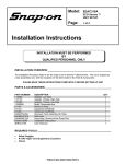
Mini-GASS ™ Gas Analysis Sampling System User Manual PERMA PURE 8 Executive Drive Toms River, N.J. 08755 Phone: 800-337-3762 732-244-0010 Fax: 732-244-8140 e-mail: [email protected] Web Site: www.permapure.com TABLE OF CONTENTS 1. Introduction.....................................................................................................................6 2. Mini-GASS Components.................................................................................................7 2.1 Probe (Optional) 2.2 Probe Blowback (Optional) 2.3 2.4 Filtration Automatic Filter Drain (Optional) 2.5 2.6 2.7 2.8 2.9 2.10 Sample Pump (Optional) Nafion Dryer Ammonia Scrubber (Optional) Purge Air Dryer (Optional) Purge Air Eductor (Optional) Z-Purge (Optional) 3. Installation.....................................................................................................................10 3.1 Mounting 3.2 Electrical Connection 3.3 Plumbing a. Sample Connection b. Purge Connection c. Filter Drain Connection (Optional) d. Purge Exhaust e. Purge Eductor Inlet Connection (Optional) f. Steam Connection (Optional) 4. Start-Up Procedure........................................................................................................14 4.1 Setup Check 4.2 Automatic Filter Drain Control (Optional) 4.3 Temperature Control a. PID Electronic Temperature Control b. Steam Temperature Control c. Safety Interlocks (SIS2/SIVS2) 4.4 Preheating the System 5. System Fine Tuning.......................................................................................................17 5.1 Steam Heated Systems 5.2 Electrically Heated Systems 6. Maintenance..................................................................................................................18 6.1 Filters 6.2 Dryers 6.3 Ammonia Scrubber 6.4 Fuse Mini-GASS User Manual 2 APPENDIX A: General ............................................................................................................20 1. Specifications 2. Wiring Diagram APPENDIX B: Dryer Element Replacement ............................................................................22 1. PD Dryer Replacement with Two Part End Fittings 2. PD Dryer Replacement with One Part Molded Fitting APPENDIX C: Replacement Parts List for Mini-GASS ............................................................23 APPENDIX D: Probe System ..................................................................................................24 1. Flange Mounted with Integral Sampling Probe and Filter Blowback Installation 2. Plumbing 3. Blow Back Operation 4. Startup 5. Maintenance 6. Flow Schematic APPENDIX E: Model Drawings................................................................................................28 APPENDIX F: “Z-Purge”..........................................................................................................31 1. Z-Purge Operation 2. Troubleshooting 3. Helpful Hints Mini-GASS User Manual 3 WARNING Thank you for purchasing sample gas conditioning equipment from Perma Pure LLC. We want your new sample gas conditioning equipment to operate safely. Anyone who installs or uses this equipment should read this publication before installing or operating this equipment. To minimize the risk of potential safety problems, you should follow all applicable local and national codes that regulate the installation and operation of your equipment. These codes vary from area to area and usually change with time. It is your responsibility to determine which codes should be followed and to verify the equipment, installation and operation is in compliance with the latest revision of these codes. At a minimum, you should follow all applicable sections of the National Fire Code, National Electrical Code, and the codes of the National Electrical Manufacturer’s Association (NEMA). There may be local regulatory or government offices that can also help determine which codes and standards are necessary for safe installation and operation. Equipment damage or serious personal injury can result from the failure to follow all applicable codes and standards. We do not guarantee the products described in this publication are suitable for your particular application, nor do we assume any responsibility for your system design, installation or operation. This product should not be operated in any manner that is inconsistent with its intended use. If you have any questions concerning the installation or operation of this equipment, or you need additional information, please call us at 1-800-337-3762. TRADEMARKS This publication is based on information that was available at the time it was printed. At Perma Pure we constantly strive to improve our products and services, so we reserve the right to make changes to the products and/or publications at any time without notice and without any obligation. This publication may also discuss features that may not be available in certain revisions of the product. TRADEMARKS Trademarks Nafion® and Teflon® are registered trademarks of EI DuPont de Nemours Copyright 1996-2005, Perma Pure LLC. All Rights Reserved. Mini-GASS User Manual 4 WARRANTY AND DISCLAIMERS: Seller warrants that product supplied hereunder shall, at the time of delivery to Buyer, conform to the published specifications of Seller and be free from defects in material and workmanship under normal use and service. Seller’s sole obligation and liability under this warranty is limited to the repair or replacement at its factory, at Seller’s option, of any such product which proves defective within one year after the date of original shipment from seller’s factory (or for a normal usable lifetime if the product is a disposable or expendable item) and is found to be defective in material or workmanship by Seller’s inspection. Buyer agrees that (1) any technical advice, information, suggestions, or recommendations given to Buyer by Seller or any representative of Seller with respect to the product or the suitability or desirability of the product for any particular use or application are based solely on the general knowledge of Seller, are intended for information guidance only, and do not constitute any representation or warranty by Seller that the product shall in fact be suitable or desirable for any particular use or application; (2) Buyer takes sole responsibility for the use and applications to which the product is put and Buyer shall conduct all testing and analysis necessary to validate the use and application to which Buyer puts the product for which Buyer may recommend the use or application of the product by others; and (3) the characteristics, specifications, and/or properties of the product may be affected by the processing, treatment, handling, and/or manufacturing of the product by Buyer or others and Seller takes no responsibility for the nature or consequence of such operations or as to the suitability of the product for the purposes intended to be used by Buyer or others after being subjected to such operations. SELLER MAKES NO OTHER WARRANTY, EXPRESS OR IMPLIED, OF THE PRODUCT SUPPLIED HEREUNDER, INCLUDING, WITHOUT LIMITATIONS, IMPLIED WARRANTIES OF MERCHANTABILITY AND FITNESS FOR PARTICULAR PURPOSE, AND ALL SUCH WARRANTIES ARE HEREBY EXPRESSLY EXCLUDED. SELLER SHALL HAVE NO LIABILITY FOR LOSS OF PROFITS, OR SPECIAL, INCIDENTAL, OR CONSEQUENTIAL DAMAGES UNDER ANY CIRCUMSTANCES OR LEGAL THEORY, WHETHER BASED ON NEGLIGENCE, BREACH OF WARRANTY, STRICT LIABILITY, TORT, CONTRACT, OR OTHERWISE. SELLER SHALL IN NO EVENT BE LIABLE IN RESPECT OF THIS ORDER AND OR PRODUCT DELIVERED ON ACCOUNT OF THIS ORDER FOR ANY AMOUNT GREATER THAN THAT PAID TO SELLER ON ACCOUNT OF THIS ORDER. Mini-GASS User Manual 5 1. Introduction Perma Pure Mini-GASS sample pre-conditioning systems are designed to prepare gas samples for analysis. The Mini-GASS system will remove particulates, mists, and water vapor without removing the compounds being monitored. Figure 1 below gives a general overview of a Mini-GASS system (Model MG-1228). Standard Features Include: - Heated Enclosure - Filter – Particulate and/or Coalescing - Perma Pure Nafion Gas Dryer - Temperature Controller - Dryer Purge Flow Controls Options: - Purge Air Dryer - Sample Pump - Filter Drain - Ammonia Scrubber - Purge Air Eductor - Z-Purge - Probe - Automatic Blowback 125 8" SAMPLE INLET SEALING FITTING FOR 112" O.D. HEATED LINE PURGE EXHAUST PORT 1 4" NPT FEMALE 1" 128 NAFION MEMBRANE DRYER MODEL PD-200T-24SA PURGE EXHAUST TEMPERATURE SENSOR HEATED BACKPLATE 343 4" HEATLESS DRYER OPTION BELOW FRONT PANEL 295 8" MEMBRANE DRYER PURGE AIR FLOWMETER DIGITAL ELECTRONIC TEMPERATURE CONTROLLER PURGE FLOWRATE Mini-G.A.S.S. TM FLOWMETER SUPPLY PRESSURE REGULATOR Gas Analysis Sampling System FILTER DRAIN TIMER SETTINGS ON TIME DELAY IN MINUTES COMBINE SWITCHES IN ON POSITION FOR TOTAL TIME DELAY 0.1 0.2 0.4 0.8 1.6 3.2 6.4 12.8 25.6 51.2 ON OFF OFF 30 TIME DELAY IN HOURS 25 0.25 0.5 1 2 4 8 16 32 64 128 ON 20 15 10 OFF 5 POWER SWITCH PURGE AIR EXHAUST TEMPERATURE 700 * 1 Decrease Increase FLOWMETER SUPPLY PRESSURE GAUGE 2 CAL 3200 10 ON S FU E US F US E I E F 0 5 FUSE TYPE AGC 5.0 A. 120 VAC 15 psi 20 25 0 30 OFF Increase Decrease POWER PRESSURE ADJ. FLOWMETER SUPPLY PRESSURE DRY SAMPLE OUTLET 316 SS -1 4" NPT FEMALE POWER CONNECTION 1 2" CONDUIT HUB 110/220 VAC PURGE AIR INLET 1 4" NPT FEMALE FUSE HEATLESS DRYER PURGE AIR EXHAUST 1 4" NPT FEMALE Figure 1 Mini-GASS User Manual 6 2. Mini-GASS Components 2.1 Probe and Probe Filter (optional): The Mini-GASS Probe and Probe Filter eliminates the need for a heated line by mounting the conditioning system directly on the stack. Once sample is drawn from the stack, it is passed through a 2 micron ceramic filter to remove oils and acid aerosols. Sample is dried and cooled immediately after removal from stack to minimize changes in sample composition (Refer to Appendix D for Installation Instructions). 2.2 Probe Blowback (optional): The optional blowback assembly to minimize maintenance of the probe filter by forcing air back through the element and releasing the particles back into the stack (Refer to Appendix D for Installation Instructions). 2.3 Filtration: The sample is passed through a 1μ filter to remove particulates and aerosols. The standard filter in the Mini-GASS system has a borosilicate glass filter element with a fluorocarbon binder. This element is disposable and will withstand high sample temperatures. In addition to removing particulates, it coalesces liquid aerosols and droplets. Two flow patterns are possible with this filter: 1. Particulate Filter: Filter installed with flow passing from outside to the inside of the element. With this installation, collected particulates will build up on outside surface of the element allowing visual inspection of its condition. 2. Coalescing and Particulate Filter (See Figure 2): Filter is installed with flow passing from inside of element to the outside. An automatic drain is usually installed to remove the condensate. Figure 2 2.4 Automatic Filter Drain (optional): If coalescing is anticipated, system should be fitted with automatic filter drain to periodically remove collected liquid mists. In most cases, these mists will be acid mists. Automatic drain is available in vacuum or pressurized style. 1. Vacuum Configuration: Collected liquid is withdrawn from filter drain port by a vacuum created by an eductor expanding compressed air through a venturi. This is done in cycles and controlled by adjustable digital timer that switches a solenoid valve controlling compressed air supply. Mini-GASS User Manual 7 2. Pressurized Configuration: An eductor is not required since a vacuum is not needed to withdraw the sample. Therefore, condensate withdraw is directly controlled by the solenoid valve. Cycle times can be varied and will be dependent on the amount of liquid present in sample. 2.5 Sample Pump (optional): The sample pump draws the sample and supplies it to the analyzer. It supplies up to 5 liters per minute of sample. The typical pump location is between the filter and the ammonia scrubber. The head of the pump will be located in the heated section of the system, with the motor located in the control section. This configuration keeps pump head at a temperature above dewpoint of the sample preventing condensation from forming. 2.6 Nafion®Dryer: The Perma Pure Nafion membrane dryer is installed downstream of the filter. As sample enters the dryer, flow splits into a number of small diameter Nafion tubes arranged in a parallel bundle as shown in Figure 3 below. After sample enters one of these tubes it comes in contact with the Nafion membrane walls. The membrane selectively removes water vapor from the sample by a process of permeation distillation. Water vapor travels through the tubing walls driven by the difference in partial water vapor pressure on the opposing sides of the membrane. As the sample flows from inlet to outlet water is continually removed, reducing the sample dew point as it travels through the dryer. Figure 3 Dry purge gas enters the dryer at the sample outlet end and performs two functions: 1. 2. Provides a medium for water vapor from the sample to be carried away. Creates a temperature gradient along length of dryer. Ambient purge air enters the dryer at sample outlet, keeping that portion of dryer cooled. This counter current flow is required to produce a temperature gradient along the length of the dryer. To effectively maintain the gradient, the temperature of purge gas exhaust is monitored and controlled by an electronic temperature controller. As purge gas passes through the dryer it is heated to the desired sample inlet temperature. This gradient allows for both rapid vapor removal and decreased final dew point. If the purge gas temperature begins to fall below the programmed temperature, the system’s backplate will heat. An aluminum heating block will conduct energy from the backplate to the dryer’s shell tube. Purge gas traveling through the dryer’s shell acquires heat from the shell. This process allows final temperature of the purge gas to be closely controlled and a consistent temperature gradient will be maintained. Mini-GASS User Manual 8 It is important that the dryer removes water in vapor state only. If liquid water is introduced into the dryer, efficiency will decline and the dryer could fail to perform altogether. Tubing elongates approximately 10% over its dry length when saturated with liquid water causing tubing to kink inside housing. Nafion dryers will operate most efficiently when a portion of the dryer is heated to prevent sample from condensing. 2.7 Ammonia Scrubber (optional): The optional ammonia scrubbing canister must be used when ammonia or urea is used for the purpose of lowering NOx levels or any time ammonia is present in sample stream. Ammonia salts can deposit in dryer tubes and cause permanent loss of drying efficiency if not removed from the sample stream. An ammonia scrubber consists of a polysulfone and 316 SS housing filled with a phosphoric acid based media and inert ceramic saddles. This media will require periodic replacement. See section 6.3 for replacement instructions. 2.8 Purge Heatless Air Dryer (optional): If -40°C dewpoint purge air is not available, a heatless air dryer can be installed in the Mini-GASS to dry the compressed air supply. Outlet of heatless dryer will be connected to standard purge gas flow controls. Operation of heatless dryer is fully automatic and continuous, and should not require any maintenance as long as oil free compressed air is used. 2.9 Purge Air Eductor (optional): When the sample is under more than five inches of water vacuum, a purge air eductor is required. Eductor generates a vacuum to draw condensate from filter and drop pressure of purge gas to prevent collapsing of Nafion tubing. 2.10 Z-Purge (optional): For hazardous environments to meet Class I, Division II specifications (Refer to Appendix F). Mini-GASS User Manual 9 3. Installation (Refer to Figure 4 for reference) 3.1 Mounting Unit should be shielded from direct rain and snow. Do not install outdoors if temperature will fall below -10°C. Probe - refer to Appendix D Automatic Blowback -refer to Appendix D Z-Purge - refer to Appendix F General flow schematic - refer to Figure 4 1. Install Mini-GASS system on vertical surface with dryer/filter compartment on top and control compartment on bottom. 2. Place mounting feet on each corner of enclosure with slotted end protruding at 45 degree angle from enclosure. 3. Drop mounting screw in from top and tighten into foot. Figure 4 Mini-GASS User Manual 10 3.2 Electrical Connection Mini-GASS Model # 1220, 1214, and 2812P (Portable) have a power cord and plug for 110 VAC and a power cord with pigtail wires for the 220 VAC version. Mini-GASS Model # 1228 and 1235: Connect power supply line to terminal block located on the backplate of the control enclosure inside 1/2” conduit hub. Refer to Figure 5 for color coding. L1 N G Figure 5 Alarm Relays: The SIVS2 has a 6 pole terminal block that will allow for field wiring of alarm relays for connection of external alarm equipment (refer to Figure 6). Relay contacts are rated at 250 VAC, 3A resistive. Low Purge Air Flow Alarm Relay Low Dryer Temperature Alarm Relay N.C. COM N.C. N.O. N.O. COM Note: It is recommended that a fused disconnect (not provided) be installed in power line coming into system. Power can then be shut off before performing any maintenance or service procedures. Figure 6 Mini-GASS User Manual 11 3.3 Plumbing a. Sample Connection - Mini-GASS with Probe refer to Appendix C With Optional Heated Line 1. Install heated line sealing fitting by threading hub into sleeve. 2. Ensure o-ring seal is installed on outside of enclosure (between sleeve and enclosure wall). 3. Run heated sample line through entry seal and into enclosure. 4. Connect sample line to compression fitting (labeled “Wet Sample In”). 5. Shrink entry seal tubing around heated sample line with heat gun. 6. Connect sample outlet port of Mini-GASS to sample line running to analyzers. High temperature heated line is not necessary for this connection. If sample line will be exposed to freezing temperatures, freeze protected line is suggested. Without Heated Line 1. Connect sample line to bulkhead fitting (labeled “Sample Gas In”). 2. Connect sample outlet from Mini-GASS (labeled “Dry Sample Out”) to sample line running to analyzer. b. Purge Air Supply Instrument Air Purge gas must be of instrument grade with dew point no higher than –40OC. 1. On model MG-1214, purge gas should be supplied to dryer via 0-30 slpm flowmeter and regulator capable of supplying 0-50 psig. All other models come with control panel which includes flowmeter and regulator. 2. Connect regulated purge gas supply line to 1/4" female NPT purge inlet port of membrane dryer (labeled “Instrument Air”). Heatless Dryer (Optional) 1. Connect oil free compressed air line to port (labeled “Purge Gas Inlet”). An oil coalescing pre-filter is recommended. 2. A 1/4” female NPT bulkhead fitting on bottom of enclosure is heatless dryer purge air exhaust. Humid air can be vented to atmosphere or piped to remote location. Mini-GASS User Manual 12 c. Filter Drain Connection Connect line from eductor outlet to designated collection/exhaust basin containing acid absorption media to prevent release of exhaust to surrounding. 1/4” I.D. tubing can be used for runs up to 10 feet, or larger I.D. tubing for longer exhaust lines. Line should not restrict purge flow. d. Purge Exhaust Purge exhaust may contain liquid water. A line can be connected from purge outlet to remote area if desired. Line should not restrict purge flow. 1/4" I.D. tubing can be used for runs up to 10 feet, or larger I.D. tubing for longer exhaust lines. e. Purge Eductor Inlet Connection Connect air supply line to compression fitting (labeled “Instrument Air”). f. Steam Connection (Optional - Refer to Figure 7) 1. Insulate supply line to steam control valve. 2. Insulate supply line between valve and steam coil. 3. Supply low pressure steam (50 psig max.) to steam coil. Do not exceed this pressure or overheating may occur. Outlet end of steam coil located at lower left side of enclosure is connected to a thermostatic steam trap to allow condensed steam to drain in a controlled manner. Condensate can be piped to a wastewater drain or to condensate recovery system. Figure 7 Mini-GASS User Manual 13 4. Start-Up Procedure 4.1 Setup Check 1. Check that electrical, sample, purge, drain, and/or steam connections have been made. 2. Turn on compressed or instrument air to system. 4.2 Automatic Filter Drain Control (Optional) Automatic filter drain is controlled by a repeat cycle timer that operates a solenoid valve. Two DIP switches are located on timing device to control drain and cycle times located on backside of control panel. Standard factory setting is to drain for 0.1 minute once every 24 hours. Drain time (left DIP switch) 0.1 minutes (1st switch on – all others off) to 102.3 minutes (all switches on) Cycle time (right DIP switch) 1 hour (1st switch on – all others off) to 1023 hours (all switches on) 1. Adjust purge air pressure regulator to about 15 psig. Sample under vacuum: Purge air regulator will control air pressure to eductor of the automatic filter drain. Regulator must be set to provide ample vacuum to remove filter condensate but not excessive enough to cause interruption in sample flow to analyzers. Under positive pressure: Condensate drain flow is directly controlled by solenoid valve. When solenoid valve is actuated(opened), positive pressure in filter housing purges condensate out of system through drain line. 2. Initially adjust DIP switches on drain timer to drain for 6 seconds every 24 hours. Time on switches is additive. Left switch should have only top 0.1 min. switch in the “ON” position and right switch should have 8 and 16 hr. switches in the “ON” position. Time periods may need further adjustment after system has been in operation. Mini-GASS User Manual 14 4.3 Temperature Control PID Electronic Temperature Controller 1. Press and hold “” key (Refer to Figure 8). 2. Press either up or down key to adjust setpoint. Setpoint temperature will change one °C with each press of arrow key. 3. When desired temperature is reached, release both keys. NOTE: MG-1228, 2812P, and 1235 systems have a low temperature alarm that is programmed into controller. Default temperature setting for alarm is 5OC below setpoint temperature. Refer to enclosed CAL Controls temperature controller manual and for more information. Figure 8 Steam Temperature Control Steam heated systems are regulated by a thermostatic steam control valve located in the purge air exhaust stream. This valve is preset at the factory to an appropriate temperature determined by sample conditions. A typical setpoint temperature is 180OF which is the approximate temperature of the purge air exhaust as indicated by analog thermometer located in the purge air exhaust stream. Safety Interlocks (SIVS2) Systems equipped with the SIVS2 interlock option automatically shuts off the sample pump or sample control valve in the event of low purge airflow or low temperature in the system. To accomplish this, a differential pressure switch in the purge air inlet senses the flow of purge air and energizes a relay. This relay then sends power to the contacts of a second relay, which will energize only when the temperature set point has been reached. After energizing, this second relay sends power to the sample valve and the valve will open and allow sample flow. Under normal operating conditions both safety relays will remain energized (When the system is operating normally, open contacts will close and remain closed). Alarm relays may be field wired to initiate an external alarm. Mini-GASS User Manual 15 4.4 Preheating the System 1. Turn on AC power or steam to system. WARNING! On AC powered units, temperature control display should light. DO NOT BEGIN SAMPLE FLOW AT THIS TIME! Check purge air is flowing immediately after turning on AC power or steam. If, for any reason, there is no purge air or flow is inadequate, turn off AC power or steam before attempting to locate problem. OPERATING SYSTEM WITH LITTLE OR NO PURGE AIR CAN CAUSE DAMAGE TO MEMBRANE DRYER ASSEMBLY. 2. Set purge air pressure to 15 psig. 3. Adjust purge air flow to 20 l/min. 4. Set purge air eductor vacuum level to 5 in-Hg (if applicable). 5. Ensure purge air is exhausting from system. 6. On systems with SIS2 or SIVS2 option, temperature controller will be alternately displaying -AL- and actual purge air exhaust temperature until purge air temperature comes within 5 OC of setpoint temperature. 7. Allow 15 - 30 minutes of additional heating time after system has come to setpoint temperature. Sample flow may be started. For Mini-GASS with a pump, when set on “AUTO” mode, pump will turn on when unit has reached temperature and purge gas is sensed. Mini-GASS User Manual 16 5. System Fine Tuning Temperature Adjustment 5.1. Steam Heated Systems Steam control valve is factory set to 180OF and is normally not field adjustable. This temperature is adequate for most applications in which sample gas water content is not in excess of 50% water vapor by volume. Consult factory if condensation in sample tubing is detected. 5.2. Electrically Heated Systems 1. Check that no condensate is present in sample line between filter and dryer. 2. If water droplets are visible, increase temperature of filter/dryer compartment by 5°C. 3. Allow about ½ hour for system to stabilize and then check again for condensate. 4. If necessary, continue to increase temperature at 5°C intervals until condensate is no longer visible. Do not exceed 100°C! Maximum system temperature is 100°C. Operation above this temperature can cause damage to Nafion dryer. It is essential that purge gas flows continuously and setpoint temperature is not above 100°°C to prevent damage to dryer. Mini-GASS User Manual 17 6. Maintenance 6.1 Filters If system is fitted with a pre-filter, it should be checked regularly to ensure that the element is in good condition. If element appears to be dirty or begins to cause flow restriction in system, it should be replaced. Filter Element Replacement (Refer to Figure 9) 1. 2. 3. 4. 5. 6. 7. 8. 9. Loosen bolt on bottom of filter. Gently pull apart assembly and remove old element. Place new element into grooves in top and bottom of housing. When re-assembling, inspect for o-rings on top and bottom caps and on center bolt. Install glass shell onto bottom piece. Place new element in groove in bottom piece. Be sure that element is seated correctly and parallel to glass shell. Carefully mate bottom assembly onto top piece. Slight twisting motion may be required to allow shell to slip over o-ring seal. Visually make sure element is seated correctly in top groove. Replace bolt through hole in bottom piece and screw clockwise into top piece. Do not over-tighten center bolt. It should be just tight enough so it does not vibrate loose. Over-tightening will not help the filter to seal. Top Cap O-ring Shell Bottom Cap Bolt Figure 9 Mini-GASS User Manual 18 6.2 Dryers Under normal conditions, Perma Pure dryers require little maintenance and can last for several years. However, if there is no pre-filter and the tubing becomes clogged or saturated with water, the dryer may require cleaning or repair. When disassembling the dryer, note that the end fittings on the PD-SERIES dryer can be easily rotated on the shell tube. This rotation should be avoided to prevent twisting the membrane tubes inside the shell. Refer to Appendix B for PD dryer element replacement. 6.3 Ammonia Scrubber Media Replacement: When deposits are visible on 75% of the scrubber, scrubbing media needs to be replaced. 1. Unscrew thumbscrew on bottom of housing. 2. Swing yoke to one side. 3. Separate housing and bottom cap as an assembly from top cap. 4. Remove spring and top screen. 5. Remove old media and dispose of properly (rinse housing with soapy water to clean). 6. Fill housing with 50cc of Berl Saddles (tap housing to allow material to settle). 7. Pour 150cc of Scrubbing Media (tap housing to allow material to settle). 8. Replace stainless steel screen on top of media. 9. Replace spring on top of screen. 10. Clean o-rings on shell and inside top manifold (replace if necessary). 11. Place center tube into o-ring seal in top cap. 12. Push and twist to seal housing around o-ring. 13. Replace yoke and finger tighten thumbscrew (do not overtighten). 6.4 Fuse Fuse Replacement 1. 2. 3. Turn cap marked “FUSE” counter-clockwise ¼ turn and the fuse holder will come out. Remove the blown fuse and replace with one of equal amperage rating. The standard fuse is a BUSS type AGC or equivalent. After installing correct replacement fuse, re-install fuse holder by pressing inward and twisting ¼ turn clockwise. Mini-GASS User Manual 19 APPENDIX A 1. Specifications MAXIMUM SAMPLE FLOW RATE: 0 TO 10 LITER/MIN MAXIMUM INLET SAMPLE TEMPERATURE: 250°F W/SST FILTER 230°F W/KYNAR FILTER MAXIMUM GAS SAMPLE WATER VAPOR CONTENT: 30% OUTLET SAMPLE DEW POINT: 26°F (-4°C) at 10 L/MIN 12°F (-12°C) at 5 L/MIN -12°F (-25°C) at 2 L/MIN 36°F (2°C) at 10 L/MIN 26°F (-4°C) at 5 L/MIN 6°F (-15°C) at 2 L/MIN 42°F(5°C) at 10 L/MIN 34°F(1°C) at 5 L/MIN 22°F(-6°C) at 2 L/MIN (With PD-200T-24SS dryer) (With PD-100T-24SS dryer) (With PD-50T-24SS dryer) SOLUBLE GAS REMOVAL RATES: NO, NO2 SO2 CO, CO2 H2S, HCl MAXIMUM GAS SAMPLE INLET PRESSURE: 20 PSIG MINIMUM GAS SAMPLE INLET PRESSURE: - WITHOUT PURGE EDUCTOR OPTION: - WITH PURGE EDUCTOR OPTION: 5" H2O VACUUM 10” H2O VACUUM GAS SAMPLE INLET FITTINGS: 1/4" or 3/8" TUBING FITTINGS GAS SAMPLE OUTLET FITTINGS: 1/4" or 3/8" TUBING FITTINGS AIR REQUIREMENTS: PURGE AIR -40°C DEW POINT MAXIMUM ONE (1) CFM ELECTRICAL REQUIREMENTS: 110/220VAC, 50/60Hz, 5.0A/2.5A (475 WATTS) FUSE: 5 AMP BUSS TYPE AGC OR EQUIVALENT ENCLOSURE: NEMA 4X, FIBERGLASS WITH POLYCARBONATE COVER DIMENSIONS: - MG-1228 - MG-2812P - MG-1220 OPERATING ENVIRONMENT: 0% 0% 0% 0% loss loss loss loss 12”W x 28”H x 7”DEEP 28”W x 12”H x 7”DEEP 12”W x 20”H x 7”DEEP -20°C TO 40°C AMBIENT TEMP. 0 TO 95% R.H. Mini-GASS User Manual 20 APPENDIX B 1. PD Dryer Replacementwith Two Part End Fittings Tools Needed: - Allen wrench 3/32 - Snap ring pliers - Pair of lightweight gloves 1. Hold coupling and shell with one hand, and remove front nut on each end with the other (Refer to Figure 10). 2. Loosen set screws on both ends of couplings using Allen wrench. 3. Remove snap ring from both sides using snap ring pliers. 4. Put on pair of lightweight gloves(protects membrane tubing from skin oils contaminating surface and reducing drying efficiency). 5. Pull element header out of housing on one side to expose o-ring. Do not rotate more than 10° in either direction. 6. Remove inner o-ring. 7. Gently pull element out other end. 8. Reverse procedure to assemble dryer. Figure 10 Mini-GASS User Manual 22 2. PD Dryer with One Part Molded Fitting TO DISASSEMBLE DRYER Tools Needed: - Phillips head screwdriver - unsharpened pencil with eraser 1. Loosen locking screws on both ends of dryer. 2. Insert eraser end of pencil into one sample port until it rests on tube header face (Refer to Figure 11). 3. Hold dryer vertically and place other end of pencil down onto a hard, slip resistant surface. 4. While supporting shell tube, push lower end fitting down with consistent pressure until it slips off shell tube. Do not attempt to pull fitting from shell tube; doing this is likely to damage dryer element tubing. 5. Repeat steps 2-4 for other end. 6. Remove one o-ring from tube header . 7. Pull tube element from opposite end of dryer. Tube Header Figure 11 TO ASSEMBLE DRYER (Refer to Figure 13) Tool Needed: - Phillips head screwdriver 1. 2. 3. 4. 5. 6. 7. 8. Sample Port Install one thick o-ring onto grooved tube header . Slip opposite tube header into dryer shell. Check for Alignment Install other thick o-ring onto groove. Push one thin o-ring into groove inside coupling (for SS Figure 12 and AL shells slip o-ring on shell across two holes). Firmly push coupling over tube header. Align purge port with hole in shell tube (Refer to Figure 12). Tighten locking screws until underside of screw head contacts top of boss. Repeat steps 4-7 for opposite end. Figure 13 Mini-GASS User Manual 23 APPENDIX C 1. Replacement Parts List for Mini-GASS Part # Description MG-DTC MG-TCS MG-SSR Digital Temperature Controller, Single Channel J-Type Thermocouple Solid State Relay MG-FM MG-PR MG-DPS MG-PG-0-30 MG-VG-0-60 SV-K10 SV-K20 Flow Meter, purge gas (0-60 L/min) Pressure Regulator, purge gas or eductor Differential Pressure Switch for Purge Flow Detection Pressure Gage, purge gas (0-30 PSI) Vacuum Gage, purge eductor (0-30"Hg) Safety Interlock Solenoid Valve, Kynar, 110V/60Hz Safety Interlock Solenoid Valve, Kynar, 220V/50Hz FF-DCV DVV-B10 DVV-B20 DVP-K10 DVP-K20 MG-DVT Drain Check Valve, Polypropylene, for vacuum drain Drain Solenoid Valve, Brass, for vacuum drain 110V/60Hz Drain Solenoid Valve, Brass, for vacuum drain 220V/50Hz Drain Solenoid Valve, Kynar, for pressure drain 110V/60Hz Drain Solenoid Valve, Kynar, for pressure drain 220V/50Hz Drain Valve Timer MG-DC MG-1412-HB MG-2112-HB Mounting Clamps for Dryer (specify dryer model) Backplate with Heater for Enclosure 1412 Backplate with Heater for Enclosure 2112 PD-50T-24E PD-100T-24E PD-200T-24E 50 Tube dryer replacement element, 24" long, includes o-rings 100 Tube dryer replacement element, 24" long, includes o-rings 200 Tube dryer replacement element, 24" long, includes o-rings FF-250-E-2.5G FF-250-G FF-250-3 AS-200-08-EB Replacement filter element Replacement glass shell Replacement O-ring set, set of 3 Media replacement for ammonia scrubber, bulk supply, 5 fillings MG-PUMPKIT Pump repair kit, Teflon diaphragm SP-270E Ceramic Filter Element for MG-1228 Mini-GASS User Manual 24 APPENDIX D 1. Flange Mounted with Integral Sampling Probe and Filter Blowback Installation Flange mounted Mini-GASS® is designed to be stack mounted on 2", 3" or 4" pipe flange. The integral sample probe and filter eliminates need for a heated umbilical line to connect stack gas sampling probe to sample conditioning system. The Mini-GASS system is attached directly to sample port flange by following the steps below: 1. Attach flange to sampling port using appropriate sized gasket and bolts. 2. Align flange holes with turnbuckle anchor at bottom. Install four appropriate sized bolts and hand tighten all four bolts evenly. Tighten with wrench (see Figure 14). 3. Install sampling probe pipe into pipe flange by inserting non-threaded end of probe pipe through flange (see Figure 15). Probe should extend into the center of the stack and pointing slightly downward to allow any entrained liquid to drain back into the stack. 4. Tighten probe pipe into flange with wrench. pipe 5. Attach one end of turnbuckle to anchor at bottom of flange and fix pin in place with cotter pin. Probe Pipe Flange Turnbuckle Figure 14 Figure 15 Mini-GASS User Manual 25 6. If system is being installed with automatic filter blow back option, install blow back system on right flange bolt (refer to Figure 16). 7. Attach pre-bent SS tubing to Mini-GASS and to blowback assembly. 8. Lift Mini-GASS system into place so union fitting on back of system can be attached to probe pipe. This is most easily accomplished with help of an assistant. 9. While holding system in place, tighten union hand tight. 10. Connect free end of turnbuckle to anchor point at middle back of system (refer to Figure 17). 11. Attach with stainless clevis pin. 12. Snap keeper wire into place. 13. Adjust turnbuckle by turning it out to increase length until union fitting is straight. Turnbuckle is used only to relieve torsional load from union fitting. 14. Tighten union fitting with a wrench. 15. Install insulation between flange and back of Mini-GASS. Insulation SS Tubing Right Flange Bolt Anchor Point Blowback Air Supply Connection Figure 16 110VAC Power Mini-GASS User Manual Figure 17 26 2. Plumbing 1. Connect blowback air line to blow back inlet port on the Mini-GASS. 2. Connect cal gas line to fitting labeled “Cal Gas Inlet”. 3. Connect 110VAC power to blow back timer Note: This also provides power to the filter in the probe. 3. Blow Back Operation The blow back option includes a timer circuit which will initiate the blow back cycle based on a regular, adjustable time period. The time cycle control turned to the far left will cycle the blow back every 15 minutes. At the far right side, the period of time between cycles is about 24 hours. The period of time between blow back cycles should be calculated to occur as often as when the filter has trapped one gram of particulates but no less frequently than once per day. A jumper placed between “AUTO OFF”and “COM” will disarm the timer. A contact closure between terminals labeled “MAN B-B” and “ COM” will initiate a blow back cycle. The blow back solenoid valve will be opened for 2 seconds when the blow back cycle is started. 4. Startup Return to Mini-GASS Startup Section 4 on pages 14-16. 5. Maintenance Changing the Filter in Blow Back/Probe Assembly 1. Unscrew black filter cap inside Mini-GASS system (use gloves if hot to touch). 2. Filter is now exposed. With a pair of pliers, pull out the old filter. 3. Inspect o-ring which are at each end of filter. Replace if they are charred or deformed. 4. Place new filter element using pliers. Ensure it is centered and in contact with o-ring. 5. Screw cap back on the filter body. Mini-GASS User Manual 27 APPENDIX E - Mini-GASS Drawings PURGE FLOWRATE Mini-G.A.S.S. TM Gas Analysis Sampling System 30 25 20 15 10 5 PURGE AIR EXHAUST TEMPERATURE 700 * 1 2 CAL 3200 10 ON S FU E US E F 0 5 FUSE F US E I 15 psi 20 25 0 30 OFF POWER PRESSURE ADJ. FLOWMETER SUPPLY PRESSURE Diagram 1. MG-1228 Style System Mini-GASS User Manual 29 Mini-GASS TM PURGE FLOWMETER SUPPLY PRESSURE PURGE FLOWRATE Gas Analysis Sampling System 10 15 psi 5 PURGE EXHAUST TEMPERATURE 20 25 0 30 30 25 20 FLOWMETER SUPPLY PRESSURE ADJ. 15 10 5 INSTRUMENT AIR INLET (30-100 PSIG) Diagram 2. MG-1220 Style System Mini-GASS User Manual 30 FLOWRATE FLOWMETER SUPPLY PRESSURE 10 15 psi 20 25 5 0 30 30 25 20 Mini-G.A.S.S. TM Gas Analysis Sampling System 15 10 PRESSURE ADJ. 5 PURGE EXHAUST TEMPERATURE 700 * 1 2 CAL 3300 I ON S FU E E US OFF E F 0 F US POWER FUSE Diagram 3. MG-2812P Portable System Diagram 4. MG-1228 Steam System Mini-GASS User Manual 31 Flange Probe Accumulator Sample Outlet Diagram 5. MG - 1228 with Probe and Blowback Mini-GASS User Manual 32 APPENDIX F Z-Purge operation System Description The Z-Purge option for the MG-2812T Gas Sampling System is based on an industry standard Bebco model 1001A Z-purge panel. It is intended to allow the general purpose enclosure of the MG-2812T to be used in Class I, Division 2 hazardous areas. While the Z-Purge system is not complicated, there are a few components that need to be understood to ensure proper and safe operation. Located on the front panel of the sampling system is a red alarm indicator light. When lit, it indicates that the pressure in the enclosure has dropped to an unacceptable level and power should be disconnected from the system. The indicator light is controlled by a differential pressure switch that senses the pressure difference between the inside and outside of the enclosure. The switch is factory adjusted to turn the alarm light on and internally disconnect power from the sampling system when the pressure indicated on the Z-purge gage falls below the “Safe” range. Located on the front panel of the Z-Purge enclosure are the two main components of the system; the adjustable pressure regulator that controls purge gas flow to the sampling system enclosure, and the pressure gage that indicates when the pressure in the sampling system enclosure is in an acceptable or “Safe” range. Two connections between the Z-Purge and sampling system enclosures are required to 1) allow purge air flow to the sampling system enclosure and 2) communicate the sampling system enclosure pressure level back to the Z-Purge gage. The second connection also allows the purge air flow to be vented through a metering orifice to the atmosphere. System Setup1. Connect a 10-125 psig compressed air source to the 1/4” NPT port on the right side of the Z-Purge enclosure. 2. Connect the two lines from the Z-purge enclosure to the sampling system enclosure. The system is calibrated to use connection tubes of this length and diameter. They should not be substituted with other length or diameter tubes. 3. Make all appropriate plumbing connections to the sampling system enclosure. It is very important that the heated line inlet connection is pressure tight. If this connection is not sealed, the Z-Purge system will not operate properly. 4. If it is necessary to adjust or check the temperature controller setting, a Z-Purge override switch is provided. This switch is located beneath the sampling system control panel. When placed in the “Setup” (ON) position, power is supplied to the sampling system control circuit regardless of the state of the Z-Purge pressure switch. Once setup of the sampling system has been completed, this switch must be returned to the “Z-Purge enable” (OFF) position for proper operation of the Z-Purge system. System Startup – Safe operation of this system requires that this procedure should be repeated any time the sampling system enclosure covers are opened for more than a few seconds. 1. Verify that AC power to the sampling system enclosure is disconnected. 2. Turn the sampling system power and sample pump switches to the ON position. 3. Adjust the membrane dryer purge air pressure to 15 psig and the flow meter to 20 lpm. Sampling systems with the sample pump option have an air line that blows air directly on the sample pump motor to prevent overheating. The “hissing” sound of the air is normal and is not a leak. 4. Close both of the sampling system enclosure covers and tighten the screws. It is not necessary to close the Z-Purge enclosure cover since this enclosure is not purged or pressurized. 5. Ensure that the vent hole at the bottom of the sampling system control enclosure in not blocked or obstructed in any way. 6. Adjust the Z-Purge pressure regulator by turning the knob clockwise until the Z-Purge gage indicates in the middle of the “Safe” area. Lock the knob by pressing it in. 7. Wait 10 minutes for the enclosure “start-up” purge. This is necessary to rid the sampling system enclosure of any hazardous gases. 8. Connect the sampling system to the appropriate AC power source. The system will turn on and the system will begin to heat up. When the system temperature comes to within 10C of the temperature controller set-point, the sample gas pump will start and sample gas will begin to flow. Z-Purge Monitoring Operation Any time the sampling system enclosure pressure falls below the “safe” range, the alarm indicator will light and AC power will be automatically disconnected from the system. This can be caused by: z Loss of the compressed air supply z Opening either of the sampling system enclosure covers z Any event that causes the sampling enclosure pressure to fall below the “Safe” range. Operation of the sampling system with the Z-Purge system disconnected (non-hazardous areas only)In non hazardous areas it is possible to operate the sampling system with the Z-Purge system enclosure disconnected. The Z-Purge feature is effectively disabled by switching the Z-Purge over-ride switch to the “Setup” (ON) position. Control system safety interlock – The interlock system is present to provide an output signal that can be used internally to stop sample flow via the sample isolation valve or optional internal sample pump. This system can also be used to provide an external output to a PLC or other control/monitoring system so that the status of the Mini-GASS can be monitored. Two relays are used to perform this function – • Low purge flow relay - A differential pressure switch across the purge air ports of the PD dryer senses the flow of purge air and energizes this relay when flow is present. A minimum purge flow rate of about 10 lpm is required. Below this flow, the alarm relay will de-energize. • Low temperature relay – The CAL 3300 temperature controller has an alarm function that is used to energize this relay when the system is operating at normal temperature. The actual point at which a low temperature alarm is triggered is Set-point minus 5C. For instance, if the temperature controller is set at 90C, the alarm relay will de-energize at 85C. The interlock system is used in the Mini-GASS to control the sample gas isolation valve or optional internal sample pump by simply supplying power to the interlock valve coil or sample pump motor via the alarm relays. Each of the relays is of a DPDT or double pole double throw design. This just means that there are two sets of normally open/normally closed (N.O./N.C.) contacts in each relay. One set of contacts is used internally and one set of contacts is provided to allow connection to an external system. • Refer the drawing MG-1228-04-12. Internally these relays are wired in series to supply power to the sample isolation valve or sample pump. To accomplish this, switched line voltage (115,230VAC, Orange wire) is supplied to the common (term. #5)connection of the low purge flow relay. From the normally open (term. 3) connection of the low purge flow relay, a brown wire connects to the common (term. 3) connection of the low temperature relay. From the normally open (term. 3) connection of the low temperature relay, a gray wire connects to the sample isolation valve or sample pump. This allows the valve to open or the pump to start only if both relays are energized. • Refer to the graphic to the right. For external connection, the second set of contacts in each relay is “dry”. No power is applied. This allows the user to determine the control voltage that will be used. A typical use of the alarm signals is, as described above, to control sample flow. The actual use is left up to the customer.