1
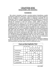
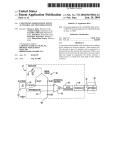
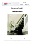
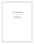
Installation Instruction
for
B&M Transpak for 1981-90
THM200-4R Transmission
Part No. 35229
© B&M Racing & Performance Products 1999
Congratulations! You have just purchased the most complete and versatile recalibration kit available for the TH200-4R transmission. We have endeavored to make the installation instructions on the following pages as clear
and complete as possible. Installation
of your Transpak can be accomplished
by anyone with minimum mechanical
experience. It is important however to
closely follow the instructions. Read
through the instructions completely
before beginning the installation.
Read each step carefully before proceeding, if you do not understand, go
back and read the step again.
NOTE: This Transpak is not a cure-all
for an ailing transmission. If your transmission is slipping or in poor general
shape, the installation of this Transpak
may worsen the condition. However on
a properly operating transmission in
average condition, the Transpak will
provide the kind of transmission performance your looking for. Check the
tool list at the end of these instructions for the tools required to install
your Transpak.
INTRODUCTION
This kit can be installed in a few
hours by carefully following the instructions. Read all instructions first to
Printed in U.S.A.
familiarize yourself with the parts
and procedures. Transmission components are precision fit, work slowly
and do not force any parts. Burrs and
dirt are the number one enemies of an
automatic transmission. Cleanliness
is very important, so a clean work
surface from which oil can easily be
removed is necessary.
This kit contains all parts necessary to obtain two different levels of
performance, depending on intended
use:
1. Heavy Duty; For passenger vehicles,
towing, police, taxi, or any other heavy
duty use. Firm shift feel, perfect for
every day street use.
2. Street; For full performance street
use. Street level produces firm positive
shifts and maximum transmission
torque capacity.
It is important to install either the
heavy duty or street levels. Do not mix
modifications from different levels.
When installing your Transpak there
are several other B&M products you
may wish to consider:
DRAIN PLUG KIT 80250: TH-200-4R
transmissions are not factory equipped
with a drain plug. The B&M Drain plug
kit is inexpensive and easy to install
and it helps eliminate the mess during
fluid change or pan removal.
TRANSMISSION OIL COOLER: We
feel that it is very important that every
vehicle used in a heavy duty application
(Towing,RV, Commercial, Police, etc.)
should have an oil cooler. Heat is the
major causes of transmission failures,
and an oil cooler is an inexpensive
safeguard against overheating and failure. B&M offers a wide range of transmission coolers to suit every need,
which are available at your B&M dealer.
TEMPERATURE GAGE KIT: 80212
Most transmission and converter failures can be traced directly to excessive heat. The B&M transmission temperature gage can save you a costly
repair bill by warning you ahead of time
of an overheated transmission. The B&M
temperature gage is extremely accurate and dependable, it comes with all
necessary hardware and is easy to
install.
DISASSEMBLY
Automatic transmissions operate
at temperatures between 150 and 250
degrees Fahrenheit. We suggest the
vehicle be allowed to cool for several
hours before disassembly to avoid burns
from hot oil and parts.
The vehicle should be raised so
there is at least two feet ground clearance for ease of installation and safety.
9500357-03
Manual link
Pressure regulator bore
Signal pipe
Electrical connector
D
1-2 accumulator
plate
D
Oil filter
bore
D
D
C
C
A
C
C
B
C
converter
solenoid
B
C
C
C
B
C
C
C
Governor
cover
1-2 accumulator
housing
D
Bolt Lengths:
T.V. lever
& bracket
Do not block
this hole
(servo vent)
Fig. 1. Valve body and accumulator installed.
T.V. exhaust check ball
lifter rod
T.V. lever and bracket
assembly
T.V. Cable link
Fig. 2. T.V. Lever and Bracket.
2
A.
B.
C.
D.
(1)
(3)
(11)
(5)
15.5 mm (0.61")
30.0 mm (1.17")
45.0 mm (1.76")
60.0 mm (2.34")
MAKE SURE THE VEHICLE IS RIGIDLY AND SECURELY SUPPORTED,
JACK STANDS, WHEEL RAMPS OR
A HOIST WORK BEST, DO NOT USE
JACKS ALONE. Have an oil drain pan
ready to catch oil and a tray on which to
put small parts so they won’t ge lost.
STEP 1. Position your drain pan beneath the transmission to catch the oil.
To remove the oil pan first remove all but
three bolts on the right hand side of the
pan. Next loosen but do not remove the
three remaining bolts. If the pan sticks
to the gasket, insert a flat screwdriver
between the pan and case and pry
down gently to break pan loose. Slowly
remove the remaining three bolts allowing the pan to tilt down and drain.
Remove all gasket material from the
pan and case flange.
STEP 2. Remove the oil filter by gently pulling it straight down. The pickup
tube has an O-ring around the end that
fits into the pump housing. Sometimes
Make sure manual link is
installed as shown
Pressure regulator bore: Make sure
retaining ring is fully seated in groove
STEP 5. Remove the 1-2 accumulator housing and plate while holding the
separator plate up to the case. Then
slowly lower the separator plate and
retrieve the (8) check balls located
above the plate. IMPORTANT: Make
note of the color, size and location of
the 1-2 and 3-4 accumulator springs for
correct reassembly. Remove all old
gasket material from these parts.
MODIFICATIONS
IFig. 3. Pressure Regulator Bore.
B&M Pressure
regulator valve
Pressure regulator
spring
Reverse boost valve
Reverse boost valve
sleeve
T.V. boost valve
T.V. boost valve
sleeve
Pressure regulator
assembly retaining
ring
Fig. 4. Pressure Regulator Assembly.
the pickup tube O-ring remains in the
pump bore, if so remove O-ring from
pump and discard both the O-ring and
filter.
STEP 3. (See Fig. 1) There are a
variety of different wiring harnesses
used on the TH-200-4R. Before proceeding further make a sketch and
some notes describing your particular
unit, recording which connectors go to
which switch. Disconnect the T.V. cable
connector from the throttle lever on
carburetor or throttle body. Remove
connectors from switches. Unplug the
wiring harness from case electrical
connector by prying the lock tab away
from the plug and pulling down on the
plug, do not pull on the wires. Removing solenoid is not required, just tie
the wires up out of the way. Remove
signal oil pipe, detent spring, and the
throttle valve lever and bracket assembly. Be careful not to lose the T.V.
exhaust checkball lifter rod when removing throttle valve lever and bracket
assembly, (see Fig. 2.)
STEP 4. Remove all valve body bolts
except the center one (See Fig. 1.)
Hold the valve body up firmly with one
hand and remove the remaining bolt
slowly. Lower the valve body and disengage the manual valve link. There are
several check balls in the valve body
along with several pints of oil. Have your
drain pan ready to catch the oil and
check balls (should they fall out.) Save
all (12) check balls in a safe place
where they won’t get lost.
3
STEP 6. All Performance Levels;
Pressure regulator. Remove the snap
ring at the end of the pressure regulator
bore in the oil pump assembly (See
Fig. 3.) Use a screwdriver to hold the
pressure regulator assembly while removing the retaining ring. If the sleeves
stick in the bore, lightly tap the sleeve
with a small rod and a mallet (piece of
2X4). Remove two sleeves with valves,
the pressure regulator spring and valve.
Reassemble the pressure regulator
assembly using the B&M pressure regulator valve and the BLUE spring supplied with the kit (See Fig. 4.) Use the
new retaining ring from the kit. Important: Make sure the retaining ring is
firmly seated in its groove when assembled.
CAUTION: The pressure regulator boost
valve train MUST be installed in the
proper order with the sleeves and valves
oriented as shown. There are several
ways the sleeves and valves can be
installed, however, only the orientation
shown will work properly. Improper installation will cause low line pressure,
resulting in slipping clutches and burnt
friction elements.
STEP 7. Heavy Duty and Street;
Separator Plate. Using the supplied
drills, enlarge the holes in your separator plate as indicated (see Fig. 5) for
the performance level desired. Pay close
attention to the diagram when locating
the holes to be enlarged so as not to
enlarge the wrong hole. Carefuly deburr
the holes after drilling.
STEP 8. Street Level Only; Line
bias valve. Rinse off valve body with
clean solvent to remove any dirt or grit.
Move to a clean working area. The valve
body consists of precision fit components which will not tolerate dirt or
burrs. Remove the roll pin retaining the
line bias valve (See Fig. 6.) Remove the
aluminum plug, valve and spring from
Drill 3/32" (.094")
Drill 5/64" (.078")
Heavy duty:
Drill 5/64" (.078")
Street only:
Drill 3/32" (.094")
Drill 3/32" (.094")
Drill 5/64" (.078")
Fig. 5. Drill Seperator Plate.
Recess on plug
faces out
Street level only:
Replace line bias spring
with red spring from kit
Install checkball in 3
places marked
Fig. 6. Valve Body Checkball Placement.
4
bore. The stock spring will not be re
used. Insert the RED spring from the kit
into the bore then install the valve,
aluminum plug, and roll pin in reverse
order of removal. Important: Do Not
dry or wipe parts with cloth rags because the lint and loose threads can
contaminate the transmission fluid and
result in jambed pressure regulator and
shift valves. Clean valve body and separator plate with clean solvent and air
dry.
ASSEMBLY
Place ckeckballs in the 8 locations
marked
3-4 accumulator
Fig. 7. Case Checkball Placement.
Valve body
gasket
Case gasket
Fig. 8. Valve Body Gaskets.
5
STEP 9. Heavy Duty and Street;
Check ball placement (See Figs. 6 &
7) Place check balls in the valve body
and case in the positions shown. Use a
dab of grease or petroleum jelly to hold
check balls in position. There are (3)
check balls located in the valve body
and (8) in the case.
STEP 10. Place the new separator plate
gaskets on the separator plate (See
Fig. 8.) Use a dab of grease or petroleum jelly to help hold the gaskets to
the plate. The gasket with the ‘C’ cut in
it goes next to the case and the gasket
with the ‘V or VB’ cut in it goes next to
the valve body. Make sure no holes in
the separator plate are covered by the
gasket.
If your gaskets become damaged
anytime during the installation of the
kit, replace them. Purchase OEM
gaskets for your specific year and
model vehicle.
STEP 11. Heavy Duty Level Only;
Insert the 3-4 accumulator pin in the
case. Over the pin place the spring and
then the accumulator piston. Use a dab
of grease or petroleum jelly to hold
components in place (See Fig. 9.)
STEP 12. Street Level Only; Insert
the 3-4 accumulator pin in the case.
Over the pin place the Red (3/8") spacer,
spring and accumulator piston. Use a
dab of grease or petroleum jelly to hold
components in place (See Fig. 10.)
STEP 13. With the 3-4 accumulator
components and case check balls in
place, place the separator plate - gasket assembly up to the case followed
by the 1-2 accumulator plate. Carefully
line up the gaskets and install the short
accumulator plate bolt. Tighten bolt
finger tight (Note: When installing valve
body and accumulator housing install
all bolts finger tight first to allow the
3-4 Accumulator
Piston
Note: Some
transmissions
come with the
3-4 accumulator springs installed above
the piston. You
should reinstall
the spring as
shown here.
Fig. 9. Heavy Duty Level Accumulator Assembly Order.
separator plate and gaskets to properly
line up before attempting to torque them.
STEP 14. Heavy Duty Level Only;
Install gasket, piston, spring and 1-2
accumulator housing in reverse order of
removal. Tighten bolts finger tight (See
Fig. 9.)
STEP 15. Street Level Only; Remove
the spring and piston from the 1-2
accumulator housing (See Fig. 10.)
and install the Blue (3/4") spacer over
the guide pin. Install piston and spring
into 1-2 accumulator housing in reverse
order of removal. With the spacer installed it will be necessary to compress
the accumulator spring when installing
the accumulator assembly. To help
keep the separator plate and gaskets
aligned thread 5 or 6 bolts into the case
at various positions. Place gasket on
accumulator housing then hold the 1-2
accumulator assembly up to the case.
As an assembly aid use two of the long
valve body bolts as guides while com-
pressing the accumulator spring. To
avoid stripped threads make sure bolts
are fully engaged before attempting to
draw the accumulator up to the case.
STEP 16. Valve body installation.
Make sure check balls are in proper
locations. Position the manual valve so
the link rod can be engaged (See Fig.
1.) Do not force the manual valve at any
time. When the link and manual valve
are fully engaged, align the valve body
and case holes then install one bolt
finger tight to hold valve body in place.
Important: Make sure the manual valve
link is located as shown.
STEP 17. Install the throttle valve (TV)
linkage onto the valve body as shown,
make sure the T.V. exhaust checkball
lifter rod is correctly assembled. (See
Fig. 2.) IMPORTANT NOTE: The T.V.
cable MUST be reset before operating vehicle refer to step 22.
STEP 18. Carefully insert ends of the
signal oil pipe in their respective bores
and push them in evenly until fully
engaged. Engage all of the remaining
bolts to finish lining up the separator
plate and gaskets (See Fig.1.) Tighten
all the valve body and accumulator
bolts to 11 NM (8 Ft. Lb.) Avoid stripped
threads, Do not over tighten bolts.
Reconnect wiring harness connectors to the terminals from which they
were removed. Refer to sketch or notes
made at Step 3. Reconnect the harness to the case connector making
sure it is firmly seated and locked.
STEP 19. Double check installation: 1:
make sure all bolts are installed and
torqued. 2: Throttle valve linkage operates freely. 3: TV exhaust checkball
(#5) lift pin is properly installed. 4:
Wiring properly connected. 5: Regulator valve retaining ring fully seated in
groove.
Place two O-rings on the end of the
new filter tube. Coat the O-rings with
clean ATF and push the tube into the
pump bore until it is fully seated. The
filter retainer clip should be located at
the small depression on the filter housing.
STEP 20. Remove all old pan gasket
material from pan and case pan rail.
Clean inside of pan with solvent. You
may want to install a B&M Drain plug kit
(80250) at this time. Install the new pan
gasket on the pan and align the holes.
Use grease or petroleum jelly to help
6
Blue 3/4" spacer
3-4 Accumulator
Piston
Note: Some
transmissions
come with the
3-4 accumulator springs installed above
the piston. You
should reinstall
the spring as
shown here.
Red 3/8"
spacer
Fig. 10. Street Level Accumulator
Assembly Order.
hold the gasket in place during installation of pan. Do not use any gasket
sealer or silicone compounds. To
prevent premature band failure make
sure the servo exhaust hole shown in
(Fig. 1) is not obstructed. Place pan up
to case, align holes and install all bolts
finger tight. Tighten bolts to 14 NM (10
Ft. Lb.) Do not over tighten bolts. If the
bolts are over tightened the gasket will
deform excessively and result in oil
leaks.
STEP 21. Fill transmission with fresh
automatic transmission fluid to the full
mark on the dip stick. You will need
about 6 quarts.
STEP 22. You must reset the TV
cable, (See Fig. 11) for the correct
procedure. Failure to reset the TV
cable will result in poor shift quality
and, or transmission failure.
STEP 23. Inspect the transmission for
leaks with engine running. Lower vehicle and check fluid level again adjust-
T.V. Cable Resetting Procedure
Fig. 11. T.V. Cable Adjustment Procedure.
ing level as required. Test drive vehicle
and recheck for leaks while transmission is hot.
TROUBLE SHOOTING
Most problems can be traced to
incorrectly installed components. If the
transmission makes unusual noise or
feels as if it is binding up, turn off the
engine immediately. Go back and recheck the entire installation.
If the problem is shift quality (slipping, hard, early, late) then do the
following:
1. CHECK TRANSMISSION OIL
LEVEL.
2. CHECK AND ADJUST TV CABLE.
3. CHECK OUTSIDE MANUAL LINKAGE.
If the above does not remedy the
problem, then perform the following diagnostic oil pressure check:
1. CHECK ENGINE TUNE
2. INSTALL A 0-2,080 kPa (0-300
PSI) OIL PRESSURE GAGE. THE LINE
PRESSURE TAP IS LOCATED JUST
ABOVE THE OUTSIDE MANUAL LINKAGE ON THE LEFT HAND SIDE OF
THE CASE.
Check oil pressures in the following
manner:
Minimum T.V. Line Pressure
Check: Set the T.V. cable (See Fig.
11) With the brakes applied, take the
line pressure readings at the selector
lever position and engine R.P.M. specified in the chart.
Maximum T.V. Line Pressure
Check: With the brakes applied, hold
or tie the T.V. cable in it’s fully extended
position then take the line pressure
readings again at the selector lever
positions and engine R.P.M specified
in the chart. IMPORTANT: Only extend the T.V. cable for this test. DO
NOT open throttle to wide open position.
Basic line pressure is controlled by
the pumps output volume and the pressure regulator valve. The T.V. system
which is controlled by the T.V. cable
causes line pressure to increase with
TOOL LIST
Hydraulic jack
Gasket Scraper
Jack stands or Wheel ramps
3/8" Drill motor
Oil drain pan
Fine cut flat file
3/8" drive ratchet wrench
10mm, 13 mm, Sockets
Wet or Dry sand paper
Grease or petroleum jelly
Small punch or scribe
Torque wrench
Small flat screwdriver
Internal retaining ring pliers
Funnel
7
increased throttle opening. Because of
system requirements line pressure is
boosted by the reverse boost valve and
sleeve assembly when the selector is
in the Reverse, D2 or D1 position.
If the oil pressure readings are low,
high or do not change when the T.V.
cable is extended (except in D2 & D1
where pressure should remain constant) then look at the pressure regulator assembly for sticking valves or incorrect order of assembly.
PARTS LIST
Pressure Regulator Valve
Pressure Regulator Spring (Blue)
Ring Retaining
Spring Line Bias (Red)
Gasket, Valve body upper
Gasket, Valve body lower
Gasket, Accumulator
Gasket, Oil pan
Oil Filter
Spacer, 3/8" (Red)
Spacer, 3/4" (Blue)
Drill, 3/32" (.094)
Drill, 5/64" (.078)
TH200-4R TRANSMISSION OIL PRESSURE *
RANGE
OIL PRESSURE AT
MINIMUM T.V. FULL T.V.
OIL PRESSURE AT
kPa
PSI
kPa
PSI
PARK & NEUTRAL
@ 1000 RPM
517
75
758
110
REVERSE
@ 1000 RPM
634
92
1380
200
DRIVE (D4) &
MANUAL THIRD (D3)
@ 1000 RPM
517
75
758
110
MANUAL SECOND (D2)
& LOW (D1)
@ 1000 RPM
772
112
772
112
* DUE TO THE LARGE VARIETY OF PRESSURE REGULATOR COMPONENTS USED IN DIFFERENT PRODUCTION
MODELS OF THE TH200-4R TRANSMISSION THE OIL PRESSURES LISTED ABOVE ARE MINIMUM VALUES. IN MOST
CASES THE PRESSURE READING WHICH YOU OBTAIN WILL BE SUBSTANTIALLY HIGHER. FOR A MORE ACCURATE
ESTIMATE CONSULT THE APPROPRIATE FACTORY SERVICE MANUAL FOR YOUR MODEL AND YEAR TRANSMISSION.
TROUBLE SHOOTING GUIDE FOR THE HYDRAMATIC TH-200-4R TRANSMISSION
SLIPS
binding, missing or unhooked.
PUMP BUZZ OR WHINE -Low oil level.
-Filter tube O-ring cut or missing.
-Filter clogged.
-Valve body bolts loose
-Low fluid level
-1-2 and/or 3-4 accumulator seals
missing or damaged.
-1-2 accumulator housing bolts
loose
-Pressure regulator valve assembly
improperly installed.
-Throttle valve linkage incorrectly
installed.
-TV cable improperly set
-Throttle valve sticking.
-Misaligned or interchanged valve
body gasket.
-Filter O-rings damaged or missing.
OVERHEATING,
FOAMING OIL AT DIPSTICK OR BREATHER
ERRATIC SHIFTING
LATE HARD SHIFTS
WILL NOT SHIFT
SOFT 2-3 SHIFTS
-Pressure regulator valve assembly
incorrectly installed.
-TV cable not set properly.
WILL NOT MOVE
-Check balls missing or mislocated.
-Manual valve not properly engaged.
-Accumulator piston(s) left out or
seals damaged.
-Pressure regulator retaining ring
did not seat in groove.
NO CONVERTER
CLUTCH APPLY
-Oil cooler has insufficient capacity.
-Oil cooler plugged.
-High fluid level.
-Shifter not properly adjusted.
-Manual valve not properly engaged.
-Low fluid level.
-Valve body gaskets damaged or
incorrectly installed
-TV cable binding or improperly set.
-Valve body gaskets incorrectly
installed
-TV cable binding or improperly set.
-Check balls missing or mislocated.
-Governor failure.
-TV cable not properly set.
-TV exhaust checkball (#5) lifter,
NO CONVERTER
CLUTCH RELEASE
NO PART THROTTLE
DOWN SHIFT
NO REVERSE AND
SLIPS IN FORWARD
RANGES
-Voltage not reaching solenoid.
-Harness plug not fully engaged.
-Connectors not on correct switches.
-Wires pinched and grounded out.
-Converter clutch valve stuck.
-Converter clutch apply valve stuck
open.
-TV cable not set properly.
-Throttle valve binding.
-Pressure regulator valve assembly
incorrectly installed.
-Pressure regulator retaining ring
did
8
not seat in groove.