1
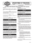
Installation Instructions
1991+ GM 4L80E Transpak Kit
Part Number 70376
©2012 B&M Racing and Performance Products
Thank you for choosing B&M, The performance company with over 50 years
experience designing and manufacturing quality high performance automotive driveline components.
Before proceeding with the installation please read all of the B&M 4L80E
Transpak Kit installation instructions
so you will be familiar with the series
of steps required to install this kit. For
other service information on your
4L80E transmission consult the appropriate factory service manual for
your vehicle.
Important Note: Since mid 1992 production the 4L80E has been assembled with a heavy duty reusable
oil pan gasket. If your pan gasket is
damaged or you have a 1991 or early
Gasket, Valve Body to
Spacer Plate
1/2”L x 51/4” ID
(orange) Spacer
TCC
Solenoid Filter
Printed in the U.S.A.
‘92 transmission, you will have to purchase a replacement oil pan gasket at
your parts supplier. An Oil Pan Gasket IS NOT supplied with this kit.
The B&M 4L80E Transpak Kit mechanically recalibrates your transmission to produce firm positive shifts, this
helps reduce clutch pack heat build up
and improves transmission durability.
This kit does not change or modify shift
point RPM in any range. All transmission shift point RPM and pressure control functions remain under full PCM
(Powertrain Control Module) control as
they were originally.
No recalibration kit can fix an already
ailing transmission. If your 4L80E is
slipping, overheating, shifting irregularly
or making noise, you should have it
Parts in Kit
Gasket, Case to
Spacer Plate
1/2”L x 5/16”ID (green)
Spacer
Press Regulator
(red) & 3rd
Accumulator (blue)
springs
Gasket, Accumulator
Housing
3/8”L x 1/4”ID (white)
Spacer
Oil Filter with
Seal
1
repaired before or, in conjunction with
the installation of your B&M 4L80E
Shift Improver Kit.
GENERAL 4L80E INFORMATION
B&M’s 4L80E Transpak Kit was designed to provide firm positive shift
quality and improve transmission durability in original vehicle installations,
especially those with moderate engine
power improvements. This kit was not
designed for and is not suitable for all
out racing applications.
Your 4L80E Transmission is controlled
by the PCM which has full control of
the 4L80E’s operation. All of the parameters that control fluid pressures,
shift point RPM and TCC (Torque Converter Clutch) Iockup speed have been
preprogramed into the PCM at the
Drill (5/64, 3/32, #32)
Shifter
Solenoid Filter
Press Regulator
Retaining Ring
3/8” X 5/16” ID (red)
Spacer
Press Control
Solenoid Filter
Boost Valve Kit
9500865-00
Required Tools
Fine Cut
Flat File
Flat Screwdriver
Funnel
Indelible Marking
Pen
Small Retaining Ring
Pliers
Torque Wrench
Petroleum Jelly
Needle Nose
Pliers
Ratchet Wrench
Extension
2” & 8” 3/8”
Drill
T27 Torx Driver
Wrench
8mm & 10mm
Gasket Scraper
Hammer
Socket
8mm & 10mm
factory. We have designed this kit as
an easy way to overcome the less desirable features of the factory calibrated imperceptible shifts. With this
kit you can set the shifting characteristics of your 4L80E to one of two levels of performance, Heavy Duty or
High Performance Street.
- Heavy Duty level produces a solid,
noticeably firm shift when compared
to the stock shift feel.
- High Performance Street level produces a slightly quicker and more aggressive shift compared to Heavy Duty
level.
After installing the B&M Transpak Kit
the actual shift feel you get will depend on the factory PCM calibration,
AutomaticTransmission Fluid (ATF)
temperature and the type of ATF you
have used. As ATF temperature increases it becomes thinner (less viscous) which allows the fluid to flow
faster through small orifices thereby
producing faster shift rates. In addition
to the effects of temperature, each
type of ATF (B&M Trick ShiftTM ,
Dexron ® III, Type F, etc.) has a specific characteristic friction property.
This characteristic friction property is
one of the variables that determines
shift feel and clutch torque capacity.
Dexron® type ATF’s were formulated
to produce smooth imperceptible
shifts, while Type F or B&M Trick
Shift TM ATF with their higher friction
properties results in firmer shift quality than Dexron ® lll type ATF. Both
DEXRON ® III and B&M Trick ShiftTM
ATF’s are suitable for use in your
4L80E transmission. For maximum
performance and positive shift feel we
2
recommend B&M Trick ShiftTM ATF.
SPECIAL INSTRUCTIONS
Choose a clean, dirt and dust free
place to work on your 4L80E. Dirt,
loose threads from rags and pieces of
old gaskets can become lodged in
valve bores and/or separator plate orifices and cause the transmission to
malfunction. If you do not have a solvent cleaning setup available, get several cans of WD40® to clean your
parts.
Warning: Almost all cleaning solvents
pose a threat of fumes and or fire.
Make sure to use cleaning solvents
only in a well ventilated location away
from any source of ignition such as
open flames, sparks, hot water heaters, etc.
Be careful with the internal and external wiring harness. Wiring and/or connectors are easily damaged and difficult to troubleshoot if they are damaged.
VERY IMPORTANT
Use petroleum jelly to hold checkballs
and gaskets in place during installation. DO NOT use any kind of wheel
bearing grease to hold checkballs in
place, these greases do not melt or
mix readily with ATF and can block shift
and pressure control solenoid feed circuit filters and orifices, causing erratic
shifts and potentially serious transmission damage because of low line pressure.
CAUTIONS ABOUT PCM.
The MIL (Malfunction Indicator Light or
Check Engine Light) may be illuminated (turned ON) if the vehicle is
started and any of the transmission
electrical connectors are disconnected
or has wires that are broken, or have
been pinched and/or shorted. The MIL
is programmed to illuminate whenever
a system (engine or transmission)
component malfunctions and at the
same time a DTC (Diagnostic Trouble
Code) is set in the PCM. You may have
to refer to your owners manual, a GM
service manual or visit a GM dealer to
determine the source of the
malfunction(s) that cause(d) any DTC
codes to be set and the required remedy. Make sure your engine is in good
tune and any problems related to set
trouble codes are repaired BEFORE
attempting to install your B&M
Transpak Kit.
Do Not attempt to jumper the Data Link
connector to read a DTC from the PCM
in your vehicle until you have checked
your owners manual, GM service
manual, or verified with your GM dealer
that the particular PCM in your vehicle
allows jumpering the data link.
Jumpering the data link connector to
read DTC’s is not possible on any 1996
or later OBD II vehicle and can damage the PCM and result in a very expensive repair bill. Except for some
1991 to 1995 PCM’s, all others will require the use of a diagnostic scanner
to read. Some DTC codes are “hard
codes” and may require a diagnostic
scanner to turn them off after the malfunction which set the DTC has been
repaired.
If electrical power to the transmission
is cut or the PCM fails the 4L80E will
operate in “limp home” mode. If this
happens, you will only have Reverse
and Drive 2 range available.
Before installing your Shift Improver Kit
there are several other B&M products
you may wish to consider and are
available at your B&M dealer:
- TRICK SHIFTTMPERFORMANCE
ATF: The industry’s only real performance ATF. A specially blended oil
formulated with foam inhibitors, extreme pressure agents and shift improvers, this fluid assures protection
while delivering the fastest possible
shifts. You literally “Pour in performance”.
- TRANSMISSION OIL COOLER:
We feel that it is very important that
every vehicle used in heavy duty or high
performance application should have
an auxiliary oil cooler. Excessive heat
is the primary cause of transmission
failures, and an auxiliary oil cooler is
an inexpensive safeguard against overheating and failure. B&M offers a wide
range of transmission coolers to suit
every need.
- DRAIN PLUG KIT (P/N: 80250):
1991 and early 1992 model 4L80E
transmission oil pans do not come from
the factory equipped with drain plugs.
The B&M Drain plug kit is inexpensive
and easy to install. It eliminates the
mess when changing fluid or on pan
removal.
- TEMPERATURE GAUGE KIT (P/N:
80212): Most transmission and converter failures can be traced directly
to excessive heat. The B&M transmission temperature gauge can save you
a costly repair bill by warning you of
an overheated transmission. The B&M
temperature gauge comes with all necessary hardware and is easy to install.
PREPARATION FOR KIT
INSTALLATION
Automatic transmissions operate at
temperatures in the range of 150° and
250° Fahrenheit. We recommend the
vehicle be allowed to cool for several
hours before disassembly to avoid
burns from hot oil and parts. The vehicle should be raised so there is at
least 2 feet ground clearance for ease
of installation and safety.
MAKE SURE THE VEHICLE IS RIGIDLY AND SECURELY SUPPORTED,
3
JACK STANDS, WHEEL RAMPS OR
A HOIST WORK BEST, DO NOT USE
JACKS ALONE.
Have an oil drain pan ready to catch
oil and a tray on which to put small
parts so they won’t get lost.
It can never be said enough: Make sure
you have a clean, dust free place to
work. Burrs and dirt are the number
one enemies of an automatic transmission. Contamination in the valve
body or pressure regulator valve train
can result in serious transmission damage and un-predictable operation.
Transmission components are precision fit. Work slowly and do not force
any parts.
This kit contains all parts necessary
to obtain two different shift feel levels
of performance depending on the intended use:
1. Heavy Duty level: Towing, campers and, 4-wheel drive vehicles. Shift
feel is firm and positive.
2. High Performance Street level:
Dual purpose performance vehicles.
High Performance Street level produces the firmest shift feel.
DISASSEMBLY
STEP 1. Position your drain pan under the transmission to catch the
ATF.Remove oil pan by first removing
rear pan bolts, then work towards the
front. Loosen but do not remove the
three front bolts. If the pan sticks to
the gasket, insert a flat screwdriver between the pan and case and pry down
gently to break pan loose. Now slowly
back out the front three bolts to permit draining the ATF. Remove pan gasket and inspect for damage. The Oil
Pan Gasket is reusable (if not damaged) except on 1991 and early ‘92
transmissions. An Oil Pan Gasket
IS NOT included with this kit. If your
gasket is damaged, ypu will have to
purchase one at your parts supplier.
STEP 2. Remove the oil filter from
case by gripping it firmly and pulling it
straight out away from the case. Inspect the filter pickup tube seal that
is pressed into the pump housing (See
Fig. 1). If the seal and filter appear to
be in good condition they may be reused, otherwise both the seal and filter should be replaced.
STEP 3. There are several different wiring harness configurations used on the
4L80E. Before proceeding further,
make a sketch and some notes describing your particular unit, recording
Oil Filter Pickup
Tube Seal
Pressure
Regulator
Bore
Detent Spring
Pressure Switch
Assembly
Manual Valve
Detent Lever Pin
Early model units used
o-rings in the pressure
switch assembly. Make
sure to recover them
during disassembly.
Dip Stick
Stop
Lube Pipe
When installing the valve
body make sure ALL of
the screws have been
installed in the valve body
(finger tight) BEFORE
beginning to tighten and
torque the bolts.
Your Valve Body installation may appear slightly different than this one.
Reinstall the components as they were originally on your unit.
Accumulator Housing Bolts:
1991 - 1993
(1) M6 x 100mm x 8mm Hex
(5) M6 x 65mm x 8mm Hex
Valve Body Bolts:
(6) M6 x 55mm x 8mm Hex
(1) M6 x 35mm x 10mm Hex
(21) M6 x 55mm x 10mm Hex
1994 - 1996
(6) M6 x 65mm x 8mm Hex
BC = Model (will vary)
P = 4L80E Transmission
Model Year
Calendar Year
Julian Date
Figure 1: Valve Body & Trans I.D.
4
which connectors go to which solenoid
(See Fig. 1). Pay particular attention
to the location of the cable clamps and
dipstick stop bracket. Notice how the
connectors and wires are colored.
Remove connectors from pressure
switch assembly and solenoids then
tie the wires up out of the way.
STEP 4. Remove all except the center valve body bolt. Pull the lube pipe
out of the case, pulling it out first at
the front then at the rear. When removing the pressure switch, be sure
to recover all 5 switch assembly Oring seals as it is removed. Hold the
valve body firmly with one hand and
remove the remaining bolt slowly. Notice how the Manual Valve is engaged
to the detent lever as you remove the
valve body from case. Caution: There
are eight (8) check balls in the case
above the valve body along with several pints of oil (export units and some
early models have nine (9) check
balls). Have your drain pan ready to
catch the oil and check balls. Save all
the check balls in a secure place where
they won’t get lost.
STEP 5. Remove the 6 screws holding the accumulator housing to the
valve body (See Fig. 7). Be careful to
keep the 2 or 3 accumulator springs
located inside the housing aligned with
their respective bores.
STEP 6. Remove all of the old gasket
material stuck to the Case flange, Oil
Pan, Vavle Body, Spacer Plate and Accumulator Housing.
lator Valves, Booster Valve or Sleeve.
The provided Balance Oil Plug should
only be installed when the transmission is out of the vehicle because the
pump assembly needs to be out of the
unit. It is installed on the backside of
the Pressure Regulator Valve, refer to
the Sonnax instructions provided. Make
sure the retaining ring is fully seated
in its groove when assembled. If the
retaining ring is not fully seated in its
groove, the pressure regulator assembly will blow out of its bore when the
engine is started, resulting in NO LINE
pressure.
MODIFICATIONS
Reassembly
STEP 9. Replace the Pressure Control Solenoid (PCS) Filter and Shift Solenoid Feed (SSF) Filter (See Fig. 4).
in the Valve Body with the new filters
supplied in the kit. Coat the O-rings
on the filters with clean ATF prior to
installation. The PCS Filter is removed
by pulling it straight up out of the Valve
body. Remove the SSF filter by first
removing the Filter Bore Plug Retaining Pin and then the Manual Valve from
its bore. Very carefully insert an 8”
long 3/8” drive extension into the
Manual Valve bore and gently push the
SSF filter out of its bore. Reassemble
both filters in reverse order of disassembly. Remove the TCC Solenoid
Screen from the case (See Fig. 8) and
replace it with the new filter from kit.
STEP 10. Apply a few dabs of Petroleum Jelly to both sides of the CLEAN
drilled and deburred Spacer Plate then
stick the Spacer Plate Gaskets (See
Pressure Regulator
STEP 7. Heavy Duty and High Performance Street levels:
Remove the snap ring at the end of
the pressure regulator bore (See Fig.
2). Use a screwdriver to push against
the spring loaded Boost Valve sleeve
while removing the retaining ring. Remove Boost Valve Sleeve and Valve,
Pressure Regulator Spring and the
Pressure Regulator Valve. Reassemble
the pressure regulator assembly in reverse order using the supplied RED
Pressure Regulator Spring, Boost
Valve, Boost Sleeve and Retaining
Ring. Important: Early model 4L80E
(1991-early 1992) require the Boost
Valve and OEM pressure regulator
valve to be modified. Follow Sonnax
Instructions that are provided to make
the required modifications.Do not intermix early and late Pressure Regu-
Spacer Plate
STEP 8. Heavy Duty and High Performance Street levels:
Drill the orifices as indicated (See Figure 3) with the supplied drill bits. Be
careful to use the specified size drill
and only drill the holes indicated for
the Perfomance Level you have chosen. For best results first use an indelible pen to mark the holes to be
drilled on the spacer plate, and then
double check your marks against Figure 3. Drill the smaller hole sizes first.
If you incorrectly drill your spacer
plate, you can obtain one from your
GM Parts Department, B&M does not
stock 4L80E Spacer Plates. Be sure
to take the build Year and Model information (See Fig.1) located on the tag
on the right hand side of the transmission when ordering parts for your
4L80E.
5
Fig. 5) onto the appropriate sides of
the plate and line up the holes. Place
the Spacer Plate on the Valve Body
and insert several Valve Body Screws
to help line up with the holes.
Accumulators
STEP 11. Heavy Duty Level Only:
Remove the 4th Accumulator piston
from its bore (See Fig. 6). Install the
3/8” long WHITE or RED spacer over
the piston pin and reinstall the piston.
STEP 12. High performance Street
Level Only: Remove the 4th Accumulator piston from its bore (See Fig. 6).
Install the 1/2” long ORANGE or
GREEN spacer over the piston pin and
Pressure
Regulator
Bore
RED
P/R
SPRING
New
Retaining
Ring
Reassemble the Pressure
Regulator in this order
Figure 2: Pressure Regulator
HD & HPS
.078 (5/64”)
HD .078 (5/64”)
HPS .094 (3/32”)
HD .094 (3/32”)
HPS .116 (#32)
HD .094 (3/32”)
HPS .094 (3/32”)
HD & HPS
.094 (3/32”)
HD .078 (5/64”)
HPS .094 (3/32”)
HD & HPS
.116 (#32)
HD=Heavy Duty Level
HPS=High Performance Street Level
There were 3 Spacer Plate designs used in the 4L80E from 1991 to 1996. The outline and some features on
your Spacer Plate may appear slightly different when compared to the illustration. The drilled orifice locations
however are the same for all 1991 through 1996 versions.
Using an indelible pen, first mark the orifices to be drilled on your spacer plate and then double check the
marked locations against the above illustration. Drill the smaller orifice sizes first. Drilling the orifices larger
than specified will result in unpredictable shift characteristics and possible transmission damage.
reinstall the piston.
STEP 13. Heavy Duty and High Performance Street levels: Replace the
stock 3rd Accumulator Spring with the
BLUE 3rd Accumulator Spring included
in the kit (See Fig.6).
STEP 14. Stick the Accumulator gasket in place on the spacer plate with
petroleum jelly. Place the accumulator springs and housing onto valve body.
Install six (6) M6 x 65mm (Late model)
of five (5) M6 x 65mm and one (1) M9
x 100mm (early model) bolts and turn
them down evenly. Make sure all of
the Spacer Plate and Gasket holes are
lined up with the Valve Body holes then
Figure 3. Spacer Plate Modification
torque the Accumulator Housing bolts
to 11 Nm(8 lb ft).
STEP 15. Check Balls: If the transmission is in the vehicle it is easiest
to place the Check Balls (See Fig. 7)
in the appropriate positions on the
Spacer Plate and then install the Valve
Body. If the transmission is on the
bench then placing the Check Balls in
the case cavities (See Fig. 8) is the
correct placement method. Use a dab
of Petroleum Jelly to hold the Check
Balls in place. Most transmissions
will have eight (8) Check Balls although, export models and some early
models have nine (9). Only eight (8)
6
Check Ball positions are used with
this kit regardless if you originall
had nine (9) Check Balls or eight
(8).
STEP 16. Make sure the Front Servo
(See Fig. 8) is correctly installed if it
was removed or fell out of its bore while
the Valve Body was removed. Wiping
the bore dry and then coating the piston with petroleum jelly will usually help
to hold the Servo Piston up in the case
during Valve Body installation.
STEP 17. Make sure the Spacer Plate
gaskets are properly positioned and the
Check Balls are in place. Carefully assemble the Valve Body to Case while
Accumulator Housing Gasket
PCS Filter
You may have to
loosen screw and
rotate the Shift
Solenoid to remove
the SSF Filter
SSF Filter
Filter Bore Plug
Plug Retaining Pin
Figure 4: PCS and SSF Filters
TC
VB
Valve Body To Spacer Plate Gasket
Figure 5: Spacer Plate Gaskets
guiding the Detent Lever Pin into the
Manual Valve groove. Push the Valve
Body firmly against the Case and install
one (1) screw, finger tight, in the center
of the Valve Body to hold it in place. Install the Pressure Switch Assembly with
six (6) M6 x 55mm x 8mm Hex head
screws. Install the Lube Tube, remaining clips and Dip Stick Stop. When all of
the screws have been installed, torque
them to 11 Nm (8 lb ft) starting in the
center and working circularly outward.
Attach wire loom electrical connectors.
STEP 18. Install the new oil filter with
seal provided in kit (See Fig. 1) into
the case.
1991-1993
Accumulator
Housing
4th Accumulator Spacer
HD 3/8” WHITE
HPS 1/2” ORANGE
STEP 19. DOUBLE CHECK THE FOLLOWING:
1. Manual Valve Body is properly engaged with pin on detent lever.
2. All bolts are installed and torqued.
3. Wiring harness connectors are engaged to switch assembly and solenoids.
4. Pressure Regulator Retaining Ring
is fully seated in its groove.
STEP 20. Coat the Oil Filter pickup
tube with clean ATF then push the tube
into the filter seal in the case. Install
the Oil Pan and Gasket then torque
the seventeen (17) bolts to 24 Nm (18
lb ft). Fill transmission with ATF to
the full mark on dip stick. You will
need about 6 to 7 quarts. Dexron®III
1994 & UP
Accumulator
Housing
4th Accumulator Spacer
HD 3/8” RED
HPS 1/2” GREEN
TS Compensator
Spring
3rd Accumulator
Piston
TS Compensator
Piston
Spacer Plate To Case Gasket
BLUE 3rd
Accumulator
Spring
4th Accumulator
Spring & Piston
4th Accumulator
Spring & Piston
Figure 6. Accumulator Assembly
7
3rd Accumulator
Piston
BLUE 3rd
Accumulator
Spring
is fine for Heavy Duty Level applications however, we recommend B&M
Trick ShiftTMATF for High Performance
Street level applications.
With the vehicle still off the ground,
start the enging and shift the transmission through all gears. Check for
leaks around oil pan flange and drain
plug. Place selector in neutral and
check the fluid level. Turn engine off
and then lower vehicle.
STEP 21. Test drive vehicle and recheck for leaks while transmission is
hot. Check fluid level again, adjusting
level as required.
1991-1993 Accumulator
Housing shown
Use petroleum jelly to hold the
Check Balls in place.
DO NOT use grease.
# 2 This Check Ball
position is not used
#9
#5
#6
#4
# 10
Install Check Balls
EITHER on Spacer plate
OR in the Case locations
whichever is easier
#3
#8
#1
Figure 7. Check Ball Placement on Spacer Plate.
#1
#8
# 10
#3
#4
#9
#6
#5
# 2 This Check
Ball position is
not used
TCC Filter shown
pulled out of its bore
Front Servo Piston
and Spring shown
removed from bore
Figure 8. TCC Filter and Case Check Ball Locations.
8
ERROR CONDITION
WHERE TO LOOK
FOR CAUSE
High or Low Oil Pressure
Oil Pump
-
Pressure Regulator Valve Stuck.
P/R Retainnig Ring not fully seated in groove.
Cracks in Filter Pickup Tube.
Pickup Tube Seal Damaged.
Wrong grease used on reassembly (clogged solenoid
filter).
- Electrical connectors not fully engaged.
- Spacer Plate or Gaskets misassembled or damaged.
- Check Balls omitted or misassembled.
- Valve Body or Accumulator Housing bolts loose.
- Stuck “ON”
- Wrong holes drilled is Spacer Plate.
- Spacer Plate or gaskets misassembled or damaged.
- Check Balls omitted or misassembled.
- Pressure Regulator Valve Stuck.
- Wrong Spring or Spacer installed.
- Damaged or missing Accumulator Housing gasket.
- Accumulator Housing bolts loose.
- Spacer Plate or gaskets misassembled or damaged.
- Pressure Switch Assembly connector not fully engaged.
- Pressure Swith Assembly/Valve Body bolts loose.
- Manual Shift Lever Linkage misadjusted.
- Electrical connectors not fully engaged.
- (See above)
- Spacer Plate or gaskets misassembled or damaged.
- Solenoid disconnected or damaged.
- Spacer Plate or gaskets misassembled or damaged.
- Spacer Plate or gaskets misassembled or damaged.
- Solenoid disconnected or damaged.
- Spacer Plate or gaskets misassembled or damaged.
- P/R Retaining Ring not fully seated in groove.
- Manual Shift Lever Linkage Misadjusted.
- Solenoid disconnected or wiring damaged.
Oil Filter
Wire loom
Valve Body Assembly
Harsh/Soft Shifts
Pressure Control Solenoid
Valve Body Assembly
Oil Pump
Accumulator Assembly
Inconsistent or No Shifts
No or Slips in 1st Gear
Valve Body Assembly
External Linkage
Wire loom
Low Oil Pressure
Valve Body Assembly
No or Slipping 2-3 Shift
No or Slipping 3-4 Shift
Valve Body Assembly
Valve Body Assembly
No or Slipping Reverse
Valve Body Assembly
Oil Pump
External Linkage
TCC Solenoid
No TCC Apply
9
10
11
NOTE: Complement your B&M Transpak Kit with some of the following products. Check the B&M website at
www.bmracing.com for various options:
B&M Shift Plus 2
Transmission Controller
# 120001
Cast Aluminum Deep Pan
(Adds 3 qt.)
# 70295
For 4L80E 1993-1998
B&M Remote TPS
(Must be used with #120001)
# 120002
B&M Transmission Oil Cooler
# 70264 (SuperCooler)
# 70297 (Hi-Tek Cooler)
B&M Drain Plug Kit
# 80250
B&M Trick Shift TM
(For Pre-2000 vehicles)
# 80286
Technical Service
A highly trained technical service department is maintained by B&M Racing and Performance to answer your
technical questions, provide additional product information and offer various recommendations.
Technical service calls, correspondence, and warranty questions should be directed to the following address:
B&M Racing and Performance
1500 Overland Ct
West Sacramento, CA 95691
Phone (808) 544-4761
Monday-Thursday 6AM to 12PM AND 1PM to 5PM PST
Friday 6AM to 130PM
12