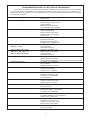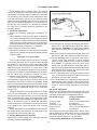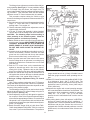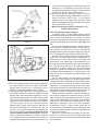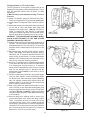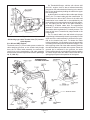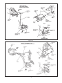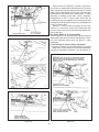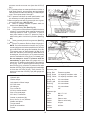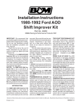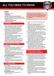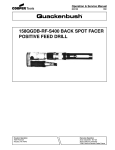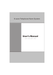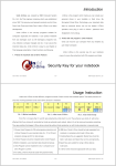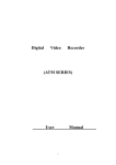
1
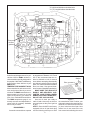
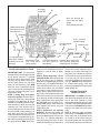
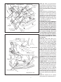
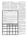
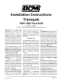
Installation Instructions
Transpak
1980-1992 Ford AOD
Part No. 40227
© 2001, 1994 B&M Racing and Performance Products
IMPORTANT: this B&M AOD
Transpak will fit all 1980 thru 1992
AOD transmissions, except for
electronoic versions. If you are installing the kit in a four wheel drive
vehicle you will have to purchase a
special (four wheel drive) filter screen,
Ford p/n E5TZ-7A098-C. We do not
recommend using the passenger car
filter screen supplied with this kit in
four wheel drive vehicle applications.
The tool list and parts list are on page
18.
We recommend that you read
through the instructions completely before beginning the installation so you can familiarize
yourself with the installation procedure and tools required.
Check the tool list at the end of
these instructions for the tools required to install your B&M AOD
Transpak.
Installation of the B&M AOD
Transpak can be accomplished by
anyone with minimum mechanical experience. It is however, important to
closely follow the instructions. Read
each step carefully before proceeding, if you do not understand, go back
and read the step again.
NOTICE: The B&M AOD Transpak
is not a cure-all for an ailing transmission. If your transmission is slipping,
chatters or is in poor general shape,
the installation of this Transpak may
worsen the condition. However on a
properly operating transmission in
average condition, the B&M AOD
Transpak will provide the kind of
transmission performance you are
looking for.
INTRODUCTION
The B&M AOD Transpak can be
installed in a few hours by carefully
following the instructions. Transmission components are precision fit,
work slowly and do not force any
parts. Burrs and dirt are the number
one enemies of an automatic transmission. Cleanliness is very important, so a clean work surface from
which oil can easily be removed is
necessary.
This kit contains all the parts necessary to obtain two different levels of
shift performance, depending on the
vehicles intended use. In several of
the steps different instructions are
given for each level:
1. Heavy Duty; Towing, campers,
motor homes and 4-wheel drive vehicles. Heavy duty level produces
firm noticeable shifts.
2. Street; Dual purpose performance
vehicles, street and strip performance
cars. Street level produces the firm,
positive shifts.
When installing your B&M AOD
Transpak there are several other
B&M products you may wish to con-
sider:
TRANSMISSION OIL COOLER We
feel that it is very important that every
vehicle used in heavy duty and hi
performance applications (racing, towing, RV, etc.) should have an oil cooler.
Heat is the major cause of transmission failures, and an oil cooler is an
inexpensive safeguard against overheating and transmission failure. B&M
offers a wide variety of transmission
coolers to suit every application. Available at your B&M dealer.
TRICK SHIFT PERFORMANCE ATF
Trick Shift performance automatic
transmission fluid is the industry’s
only real performance ATF. A specially blended oil with foam inhibitors,
extreme pressure agents and shift
improvers, this fluid assures protection while delivering the fastest possible shifts. You literally “Pour in performance.” Available at your B&M
dealer.
DRAIN PLUG KIT 80250 The AOD
transmission is not factory equipped
with a drain plug. The B&M Drain plug
kit is inexpensive and easy to install.
It eliminates the mess of pan removal
and gasket replacement normally required when changing fluid.
B&M SHIFTERS; B&M manufactures
a complete line of automatic transmission shifters ideally suited for use
with the AOD. These shifters provide
you with positive transmission control
Sections of these instructions include copyrighted materialfrom Ford Service Manuals. Reprinted with permisson of Ford Motor Company
Printed in the U.S.A.
9500427-03
"S"=(8) Short M6x30mm shoulder bolts
"L"=(17) Long M6x40mm shoulder bolts
L
L
S
L
L
L
L
L
S
S
S
L
Remove
old filter
gaskets
S
L
L
L
L
S
S
S
L
L
as well as stylish appearance for your
vehicles interior. B&M’s shifters include a model especially designed for
the popular 1980-1990 Ford Mustang.
Inquire about these shifters at your
B&M dealer.
TEMPERATURE GAUGE KIT 80212
Most transmission and converter failures can be traced directly to excessive heat. The B&M transmission temperature gage can save you a costly
repair bill by warning you ahead of
time of an overheated transmission.
The B&M temperature gage is extremely accurate and dependable, it
comes with all necessary hardware
and is easy to install.
DISASSEMBLY
Automatic transmissions operate
L
L
L
Figure 1
at temperatures between 150 F and
250 F. We recommend that the vehicle be allowed to cool for several
hours before attempting disassembly
to avoid serious burns from hot oil and
parts. The vehicle should be raised so
there is at least 2 feet ground clearance for ease of installation and safety.
MAKE SURE THE VEHICLE IS
RIGIDLY AND SECURELY SUPPORTED, JACK STANDS, WHEEL
RAMPS OR A HOIST WORK BEST,
DO NOT USE JACKS ALONE.
Have an oil drain pan ready to
catch oil and a clean tray on which to
put small parts so they won’t get lost
or dirty.
STEP 1. Since the AOD is not factory
equipped with an oil pan drain plug
use the following technique to drain
2
Gasket
Filter grommet
Figure 2
the transmission fluid. Position your
drain pan beneath the transmission to
catch the oil. Remove all but the two
(2) front bolts from the oil pan. Next
loosen but do not remove the two
front center bolts allowing the rear of
Reinforcement plates
Use shoulder bolt
for alignment
Use shoulder bolt
for alignment
Separator
plate
Detent spring
guide bolt
Gasket
Valve body
Figure 3
the pan to drop down. If the pan sticks
to the gasket, insert a flat screwdriver
between the pan and case and pry
down gently to break pan loose. Now
slowly back the bolts out to permit
draining the remaining oil. Remove
all old pan gasket material from the
pan and case.
STEP 2. Remove three (3) screws
holding the oil filter then pull the filter
straight down from the valve body.
Remove the filter grommet and gasket material from valve body. (See
Figs. 1 & 2.)
STEP 3. Remove all of the valve
body bolts except one near the center
(See Fig. 1). Hold valve body up
against case and remove the last bolt.
When removing valve body watch
out for about a pint of oil trapped
above it. Place the valve body on a
clean work surface. WARNING: Do
not place the valve body on the ground
or a dirty surface. The valve body
consists of precision fit valves and
will not tolerate dirt or burrs. Any dirt
entering the fluid circuits will jam the
shift valves and prevent the transmission from shifting.
VALVE BODY DISASSEMBLY
IMPORTANT: Pay special attention
in the following steps where some
steps refer to both Heavy Duty and
Street level modifications, while other
steps refer only to Heavy Duty or
Street level modifications. If neither
performance level is specifically referred to it means both Heavy Duty
and Street levels. It is a good idea to
3
retain all replaced parts (separator
plate, springs, etc.) for reference until
after the installation is complete and
the vehicle is satisfactorily road tested.
STEP 4. Remove 12 bolts holding
separator plate to valve body (See
Fig 3). Remove (3) reinforcement
plates and separator plate, (1) large
(orange) and (6) small (black) check
balls, and (2) relief valves with springs
(See Fig. 4). NOTE: Early 1980 valve
bodies may have (7) black check balls.
Carefully remove any remaining gasket material from reinforcement plates
and valve body surfaces. Make sure
none of the gasket debris remains in
the valve body channels to contaminate the valves. Rinse off valve body
with clean solvent to remove any dirt
or grit.
#1 orange
check ball
#2
#3
#4
Note: #2 through #8
check balls are black
rubber.
#7 checkball is not used.
Replace stock spring
with spring from kit.
See steps 6 or 7
#5
Retaining
clip
Inner pressure
regulator spring
Bore plug
(tapped hole
faces out)
#6
Pressure regulator valve
Retaining clip
Retainer
1-2 Capacity modulator valve. Inslall in
furthest bore in this
direction,
#8
Short stem TV pressure relief valve
(green spring)
Boost valve
Converter relief valve, Replace stock outer preslong stem (green or sure regulator spring with
blue spring)
red spring in kit. See step 5.
Boost valve
sleeve
Figure 4
VALVE BODY MODIFICATIONS
IMPORTANT HINT: The spring clips
at the end of the valve body bores can
fly off during removal. To prevent
losing the spring clips place a small
rag over the clip when removing it,
this will help prevent the clip from
flying off and becoming lost. B&M
does not stock replacement spring
clips. If yours are lost or damaged see
your local Ford parts supplier or try a
transmission shop.
STEP 5. Heavy Duty and Street;
Pressure regulator. Remove the retaining clip at the end of the pressure
regulator bore (See Fig. 4) Use a
screwdriver to hold the pressure regulator assembly in while removing the
retaining clip. If the sleeves stick in
the bore, lightly punch the sleeve with
a small rod and a mallet allowing it to
snap back out of the bore. Remove
Sleeve with Boost Valve and the outermost pressure regulator spring. Replace the stock outer pressure regulator spring with the RED spring sup-
plied in the kit. Reassemble pressure
regulator in reverse order of disassembly.
STEP 6. Heavy Duty Only; 1-2 Capacity Modulator. Remove the spring
clip at the end of the 1-2 Capacity
Modulator bore (See Fig. 4). Remove
the bore plug, 1-2 Capacity Modulator
valve and spring from bore. On later
model valve bodies use the M4x40
(4mm metric screw supplied in kit) in
tapped hole to assist removing bore
plug. Early valve bodies do not have
a hole in the bore plug so you will have
to pry the plug out with a small screw
driver. Replace the stock spring with
the YELLOW spring supplied in kit.
Reassemble spring, valve and bore
plug (tapped hole facing out) and
install spring clip.
STEP 7. Street Only; 1-2 Capacity
Modulator. Remove the spring clip
at the end of the 1-2 Capacity Modulator bore (See Fig. 4). Remove the
bore plug, 1-2 Capacity Modulator
valve and spring from bore. On later
model valve bodies screw the M4x10
4
(4mm metric screw supplied in kit) in
tapped hole to assist removing bore
plug. Early valve bodies do not have
a hole in the bore plug so you will have
to pry the plug out with a small flat
screw driver. Replace the stock spring
with the GREEN spring supplied in
kit. Reassemble spring, valve and
bore plug (tapped hole facing out) and
install spring clip.
SEPARATOR PLATE
MODIFICATIONS
IMPORTANT: The B&M AOD separator plate was designed to work with
any of the three versions of AOD
valve bodies produced between 1980
and 1990. The following steps explain
how to set up the B&M AOD separator
plate for your particular model valve
body.
STEP 8. Place the stock separator
plate on top of the B&M plate with the
valve body side of the plates facing
up. Install (2) of the short reinforcement plate screws and nuts (supplied
in kit) through the alignment holes as
Install bolts and nuts in holes
marked "X" for alignment during
drilling
X
B
C
A
C
X
The existing holes at position C may be larger or
smaller than 1/8" (.125"). That's OK. If these holes are
present on your separator plate use them as templates to drill 1/8" holes in the B&M separator plate.
NOTE: There will be holes and slots in the stock
separator plate which have no corresponding holes or
slots in the B&M separator plate. They are not required for operation of B&M AOD Transpak.
The stock separator plate will have one of the following:
1. No holes or slots at A, B or C.
2. A slot at position A only.
3. Slots at positions A and B, and holes at position C.
Using existing slots and holes as templates, drill two
holes as shown using 1/8" drill supplied in kit.
If your stock separator plate has no holes or slots in
these positions (A, B or C) then the B&M plate will not
have to be drilled.
Figure 5
shown. ( See Fig 5.) Align both separator plate holes and tighten the (2)
bolts until they are just snug.
STEP 9. Using the stock separator
plate as a template drill holes in the
B&M AOD separator plate as indicated in Figure 5.
Remove all sharp burrs from plate
surface with a fine flat file. Burrs can
be removed from around the edge of
the holes by lightly pressing a slightly
larger drill bit to the hole and spinning
it with your fingers.
IMPORTANT: Drill only in the areas
indicated. There are other holes in
the stock separator plate that are not
used with this kit and should not be
drilled in the B&M plate.
STEP 10. Wash and wipe any loose
chips from B&M separator plate.
DOUBLE CHECK the stock plate
against the B&M plate to make sure
all required holes have been drilled.
VALVE BODY ASSEMBLY
STEP 11. Check ball placement (See
Fig. 4) Place check balls in the valve
body in the positions shown. Use a
5
dab of grease or petroleum jelly to
hold check balls in position. The
grease will have no effect on transmission operation and will dissolve
after an hour or two of operation. Note
the location of the ORANGE #1 check
ball. The orange and black check
balls are not interchangeable.
STEP 12. Reinstall original converter
and TV pressure relief springs and
valves (See Fig. 4). Pay close attention to the spring color and relief valve
stem length. The long stem converter
relief valve can have either a green or
Retaining ring
Cover
2-3 Accumulator spring.
Replace stock spring with
blue spring from kit
Install spacer on
street level only
B&M piston seal ring
Install on piston
2-3 accumulator piston
Alignment pin
B&M piston seal
ring
Install on piston
Alignment pin
2-3 Accumulator modifications
Figure 6
in the gasket that do not have a correblue spring.
STEP 13. Visually check separator sponding holes in the separator plate.
If your gaskets become damaged
plate gaskets against the B&M AOD
anytime
during the installation of the
separator plate to make sure no holes
kit,
replace
them. Purchase stock
in the separator plate are covered by
Ford
gaskets
for your specific year
the gasket. NOTE: There will be holes
6
and model vehicle.
STEP 14. Position separator plate
gasket then separator plate on valve
body. Align gasket and separator plate
holes with those in valve body. Insert
(2) long (1.56") valve body shoulder
bolts through separator plate and
valve body as illustrated in Figure 3.
The shoulder bolts are required to
maintain gasket and plate alignment
during assembly. The shoulder bolts
must be installed in the holes indicated for proper alignment. Install (3)
reinforcing plates with (11) short bolts
tightening the bolts finger tight. Install
(1) M6x30mm (1.16") detent spring
guide bolt. (See Fig. 3.)
With all bolts just finger tight make
sure all plate and gasket holes line up
with valve body holes and the two
alignment shoulder bolts can slide in
and out freely. Torque the (12) bolts
to 80-100 lb.in. (9-11 Nm). If you do
not have a low range torque wrench,
run the bolts down until they stop
(wrist tight) then turn bolt an additional one eighth (1/8) turn. Remove
the (2) shoulder bolts used for alignment.
2-3 ACCUMULATOR
MODIFICATIONS
STEP 15. Remove retaining ring, 2-3
accumulator cover, 2-3 accumulator
spring and 2-3 accumulator piston
from 2-3 accumulator bore (See Fig.
6). Remove (2) seal rings from accumulator piston. Coat the (2) square
cut rubber rings supplied in kit with
clean AFT then install rings on piston.
Install piston back into bore.
STEP 16. Heavy Duty only; Replace
stock 2-3 accumulator spring with the
BLUE spring supplied in kit. Install
BLUE 2-3 accumulator spring, cover
and retaining ring into bore (See Fig.
6).
STEP 17. Street only; Replace stock
2-3 accumulator spring with the BLUE
spring supplied in kit. Install BLUE 23 accumulator spring, B&M 2-3 accumulator spacer, cover and retaining
ring (See Fig. 6).
FINAL ASSEMBLY
NOTE: If you are installing a B&M
shifter in other than a Mustang, this is
a good place to install the new shift
lever.
Detent spring bolt
Detent plate pin
Manual valve
Internal TV
lever
Detent lever
spring
TV
plunger
TV torsion spring
in V notch
Figure 7
Line pressure tap
Left side of case
Forward
clutch tap
TV pressure tap
Direct clutch tap
Right side of case
Figure 8
7
STEP 18. Check your parts before
proceeding, you should have (3) stock
springs and no check balls or relief
valves left over. Make sure the (12)
valve body plate bolts are properly
torqued.
STEP 19. Remove all old gasket material from the case surface. Install (2)
M6x40mm (1.56") alignment pins
(supplied in kit) into the holes shown
(See Fig. 6). Install case to separator
plate gasket over alignment pins. Use
a few dabs of grease tho hold the
gasket against the case.
CAUTION: Valve body installation
is one of the most important steps
to insure proper operation of the
AOD transmission. The valve body
must be located flush against the
case and carefully torqued exactly
as described in the following step.
Failure to follow this procedure
can result in sticking valves and
unpredictable transmission operation. If the valve body is warped or
damaged due to improper assembly it is not repairable and should
be replaced.
STEP 20. Install valve body up to
case being careful to align manual
valve with pin in detent plate (See
Fig. 7). You also have to manually
engage the TV lever between the
valve body and TV plunger. DO NOT
try to force the valve body into place,
it will go right into place with a little
patience. With the valve body sitting
flush against the case install (1) bolt
to hold the valve body in place. Make
sure the detent plate pin and internal
TV lever are properly positioned then
install (8) short M6x30mm (1.16") and
(16) M6x40mm (1.56") shoulder bolts
(See Fig. 1). Remove the alignment
pins only after all but the last two bolts
have been installed. Install ALL bolts
FINGER TIGHT. The short bolts are
installed (4) in front (1) in center and
(3) in rear of valve body. One of the
shoulder bolts holds the detent lever
spring. Starting at the center and working outward torque bolts to 80-100
lb.in. (9-11 Nm). If you do not have a
low range torque wrench, run the bolts
down until they stop (wrist tight) then
turn bolt an additional one eighth (1/8)
turn.
STEP 21. Position the TV torsion
spring against the separator plate ‘V’
notch(See Fig. 7). The TV torsion
spring pushes the TV lever against
the TV plunger. Failure to position
this spring properly will result in
erratic shifting.
STEP 22. Make sure rubber grommet
is installed in the new filter supplied
with kit. Install the cork filter gasket on
filter using a dab of grease to hold it in
place (See Fig. 2.). Coat the filter
grommet with clean ATF and install
filter on valve body. Push the filter
straight on to avoid damaging the
rubber grommet. Install (3) M6x16
(0.63") bolts and torque to 80-100
lb.in. (9-11 Nm).
STEP 23. Remove any old pan gasket material from pan and case pan
rail. Clean inside of pan with solvent.
If you recall what a mess draining the
pan was, you may want to install a
B&M Drain plug kit (80250) at this
time. Install the new pan gasket on
the pan and align the holes. Use grease
or petroleum jelly to help hold the
gasket in place during installation of
pan. Place pan up to case, align holes
and install all bolts finger tight. After
all bolts have been installed, torque
bolts to 72-124 lb. in. (8-14 Nm). If
Line Pressure check
*On the AOD transmission two pressure readings must be taken: One at idle
(closed throttle, Zero TV Press.) and another at wide open throttle
(W.O.T., Full TV Press.).
*Engine and transmission should be at normal operating temperature for
test.
*During test at W.O.T. (stall) the wheels must be locked to prevent any
vehicle motion.
*DO NOT operate at W.O.T. Stall for more than 10 seconds at a time,
followed by at least 2 minutes in Neutral at 1000 RPM to cool the oil.
*Connect a 0-300 PSI (0-2000 kPa) pressure gage to the line pressure port
located just above the control levers on the right side of the transmission
(See Fig. 8). The gage hose must be long enough to read gage while
operating engine.
*Connect a 0-100 PSI (0-690 kPa) gage (300 PSI gage will work if it’s all you
have) to the TV Pressure tap on the right hand side of the transmission
(See Fig. 8). The gage hose must be long enough to read gage while
operating engine.
*Idle pressure must be read with throttle off the fast idle cam.
*Pressures listed apply to stationary vehicle only. In 3rd and 4th gears line
pressure is lower (cut back) than shown for “all other ranges”.
Oil Pressure Specifications
Selector
Line Pressure
TV Limit Pressure
Position
PSI
PSI
(kPa)
(kPa)
At idle
In Reverse
109-129 (751-890)
0
0
All Other Ranges
74-94
0
0
(510-648)
At W.O.T. (Stall)
In Reverse
3.8L & 4.9L
264-304 (1820-2096)
74-86
(510-593)
All other engines
275-315 1896-2172)
79-91
(545-627)
3.8L & 4.9L
200-220 (1379-1517)
74-86
(510-593)
All other engines
209-229 (1441-1579)
79-91
(545-627)
All Other Ranges
8
the bolts are over tightened the gasket will deform excessively and lead
to oil leaks.
STEP 24. Fill transmission with fresh
automatic transmission fluid to the
full mark on the dip stick. We recommend B&M Trick Shift transmission
fluid for all applications, particularly
for Street Level applications. You will
need approximately 6 to 8 quarts.
TV Linkage Adjustment
STEP 25. TV Linkage Adjustment:
Normally the TV linkage does not
need to be adjusted after installing
the valve body. Proper installation of
this kit will not change the setting of
the linkage (follow instruction procedures). The linkage normally requires
adjustment only when the transmission is installed in the vehicle or when
there is a new carburetor or throttle
body installed. We recommend, however, performing a Line and TV pressure check to check whether or not
the TV Linkage is properly adjusted
(See Oil Pressure Chart). If the pressure check indicates TV linkage adjustment is required see the TV linkage adjustment section on the following pages. The pressure test will also
give you a good indication of the
transmissions condition.
Line Pressure Test Results
Low at idle in all ranges: Check for
low fluid level, clogged or damaged
filter, loose valve body bolts, stuck
pressure regulator valve, missing
pressure regulator spring or oil temperature too hot from excessive
W.O.T. test.
Low at W.O.T. but O.K. at idle:
Check for low oil level, clogged filter,
damaged or out of adjustment TV
linkage, Sticking TV or TV limit valve
in valve body.
STEP 26. Inspect the transmission
for leaks with engine running. Lower
vehicle and check fluid level again
adjusting level as required. Test drive
vehicle and recheck for leaks while
transmission is hot.
Ford Service Manuals available from
Helms Inc., Detroit, MI., (313) 8655000.
Ford service tools available from
OTC Tool and Equip., Owatonna,
MN., (507) 455-7050.
TROUBLESHOOTING GUIDE FOR THE FORD AOD TRANSMISSION
The troubleshooting guide is intended to help you identify possible causes of malfunctions that could be related
to incorrect assembly or adjustment of the transmission hydraulic system (valve body and accumulator) and or
mechanical controls. We recommend that you obtain an AOD service manual for problems related to the torque converter
or transmission hard parts.
Slow initial engagement
Harsh initial engagement
No drive in any selector position
No drive forward, but has reverse
Slips or chatters in 1st gear
(Selector in “OD”)
Slips or chatters in 2nd gear
(Selector in “OD”, OK in 1st)
Slips or chatters in Reverse
Starts in 2nd or 3rd
Incorrect shift points
NO 1-2 upshift
Mushy 1-2 shift
No 2-3 upshift
Mushy 2-3 upshift
Mushy or rough 3-4 upshift
No forced down shifts
Transmission overheats
Transmission noise
Low line pressure
Fluid level low
Engine idle too high
Loose U-joints or engine mounts
High line pressure
Sticking valves in valve body
2-3 accumulator valve damaged
Valve body leaking internally
Valve body bolts loose
Sticking valves in valve body
Manual valve pin not engaged
Fluid level low
Worn or stuck governor
Valve body bolts loose
Sticking valves in valve body
Damaged 2-3 accumulator seal
TV linkage out of adjustment
Low line pressure
Valve body bolts loose
Defective intermediate clutch
Sticking valves in valve body
Low line pressure
Valve body bolts loose
Sticking governor
Sticking valves in valve body
Cross channel leaks between case or separator plate and valve body
TV linkage out of adjustment
Worn governor
Sticking valves in valve body
TV linkage out of adjustment
Governor valve sticking
Sticking valve in valve body
Out of tune engine
Defective intermediate clutch
TV linkage out of adjustment
Low line pressure
Defective direct clutch
Convertor damper hub broken
Sticking valve in valve body
Defective 2-3 accumulator piston or seals
Low line pressure
Out of tune engine
Defective OD band or reverse drum
TV linkage out of adjustment
Defective clutch or band
TV linkage damaged or out of adjustment
Sticking valve in valve body
Too high idle speed or overheated engine
Restriction in cooler or lines
Converter overrun clutch seized
Sticking valves in valve body
Relief valve resonance (buzzing)
Oil pump cavitation
9
TV LINKAGE ADJUSTMENT
Three different types of Throttle Valve (TV) linkages
have been used on the Ford AOD transmission since its
introduction. The earliest linkage consisted of a bent rigid
rod connecting the carburetor and transmission while
most late model AOD’s use one of two different flexible
cable type linkages. NOTE: Special tools and a pressure
gage will be required depending on the particular TV
linkage type you are working on. Adjustment procedure
for each of the TV linkage types are presented in the
following sections.
1. Carburetor adjustment
Perform the following steps prior to adjusting TV
linkage.
1.1Check/adjust the engine curb idle speed to specification. Refer to the Engine/Emissions Diagnosis manual
for procedures to adjust throttle solenoid applications.
Make sure the curb idle speed is set to specification
with and without the throttle solenoid positioner (antidieseling solenoid) energized, if so equipped.
1.2Shut engine off. Remove air cleaner.
1.3De-cam the fast idle cam on the carburetor so that the
throttle lever is against the idle stop or throttle solenoid
positioner stop.
Figure 9
2.1Set carburetor at minimum idle stop as described in
steps 1 thru 3. Place shift lever in NEUTRAL and set
parking brake. CAUTION: The transmission selector
lever must be in NEUTRAL in when adjusting the TV
linkage.
2.2Back (turn CCW) the linkage lever adjusting screw all
the way out (until screw end is flush with lever face).
2.3Turn the adjusting screw in (CW) until a thin shim of
.127mm (0.005 inch) maximum, or piece of writing
paper fits snug between end of screw and throttle
lever. NOTE: To eliminate effect of friction, push
linkage lever forward (tending to close gap) and release before checking clearance between end of screw
and throttle lever. Do not apply any load on levers with
tools or hands while checking gap.
2.4Turn the adjusting screw in (CW) an additional three
turns. (Three turns are preferred. One turn minimum is
permissible if screw travel is limited).
2.5 If it is not possible to turn in adjusting screw at least one
additional turn (from initial gap) or if there was insufficient screw adjusting capacity to obtain an initial gap
in Step 5, refer to Linkage Adjustment at Transmission.
Idle Speed Adjustment
Whenever it is required to adjust idle speed by more than
50 rpm, the adjustment screw on the linkage lever at the
carburetor should also be readjusted as follows:
Idle Speed Change
Linkage Adjustment
at Carburetor
50 rpm or more
Check TV lever adjustment
decrease
at carburetor
Less than 50 rpm
No change required
50 rpm or more
Check TV lever adjustment
increase
at carburetor
After making any idle speed adjustments, always verify
that the linkage lever and throttle lever are in contact with
the throttle lever at its idle stop (or throttle solenoid
positioner) and the shift lever is in NEUTRAL.
3. Rod Linkage Adjustment at Transmission
Rod type TV control system.
The TV control linkage system consists of a linkage
lever on the carburetor, the TV control rod assembly and
an external TV control lever on the transmission. (See
Fig. 9.) The TV control rod transmits motion between the
carburetor linkage lever and the TV control lever on the
transmission. The carburetor linkage lever has an adjustment screw for limited TV linkage Adjustment. The external TV control lever actuates the internal TV control
mechanism which regulates TV control pressure.
The TV control rod is set to its proper length during
initial assembly using the sliding trunnion block at the
transmission end of the TV control rod assembly. Under
normal circumstances it should not be necessary to alter
this Adjustment. Any required adjustment can normally be
made using the adjustment screw on the carburetor
linkage lever.
When the linkage is correctly adjusted, the TV control
lever on the transmission will be at its internal stop
position when the carburetor lever is at its minimum idle
stop. There will be light contact force between the throttle
lever and the end of the linkage lever adjustment screw.
Due to the flexibility in the TV linkage the adjustment
screw would have to be backed out several turns before
a gap between the screw and throttle lever could be
detected.
Before any engine TV linkage adjustment can be done,
the throttle lever at the carburetor (or throttle body) must
be positioned at its minimum idle stop.
2. Linkage Adjustment at Carburetor
Adjust the TV control linkage at the carburetor using the
following procedure (See Fig. 9.):
10
The linkage lever adjustment screw has limited adjustment capability. (See Fig. 9.) If it is not possible to adjust
the TV linkage using this screw, the length of the TV
control rod assembly must be readjusted using the following procedure. This procedure must also be followed
whenever a new TV control rod assembly is installed.
This procedure requires raising the vehicle to give
access to the linkage components at the transmission TV
control lever.
3.1Set carburetor at its minimum idle stop as described in
steps 1-3. Place shift lever in NEUTRAL and set
parking brake. Turn engine off.
3.2 Set the carburetor linkage lever adjustment screw at
approximately half-travel.
3.3 If a new TV control rod assembly is being installed,
connect the rod to the linkage lever at the carburetor.
CAUTION: The following steps involve working in
close proximity to the exhaust system. Allow the
exhaust system to cool before proceeding.
3.4Raise vehicle so there is at least 2 feet ground clearance for ease of access. MAKE SURE THE VEHICLE
IS RIGIDLY SUPPORTED ON JACK STANDS OR
WHEEL RAMPS IF A HOIST IS NOT AVAILABLE.
DO NOT USE JACKS ALONE TO SUPPORT VEHICLE.
3.5Loosen the bolt on the sliding trunnion block on the TV
control rod assembly. Remove corrosion and road
grime from the control rod and free-up the trunnion
block so that it slides freely on the control rod.
3.6Push up on the lower end of the control rod to ensure
that the linkage lever at carburetor is touching firmly
against the throttle lever. Release force on rod. Rod
must stay up.
3.7Push the TV control lever on the transmission up
against its internal stop with a firm force, approximately 22 N (5 lbs). Tighten the bolt on the trunnion
block. Do not relax force on lever until bolt is tightened.
3.8Lower the vehicle and verify that the throttle lever is
still against the minimum idle stop or throttle solenoid
positioner stop. If not, repeat Steps 14 and 15.
4 Rod type Linkage Adjustment Using TV Control
Pressure
Note: This procedure requires the use of TV Pressure
Gauge with Hose (0-60 psi) T86L-70002-A or equivalent.
The results of the adjustment procedure depends on the
accuracy of the pressure gauge.
The following procedure may be used to check and/or
adjust the throttle valve (TV) control linkage using the TV
control pressure. (See Fig. 10.)
4.1Check/adjust the engine curb idle speed to specification required. Refer to the Engine/Emissions Diagnosis manual for appropriate procedure. Ensure the curb
idle speed is set to specification with and without the
throttle solenoid positioner (anti-diesel solenoid) energized, if so equipped.
4.2Attach Pressure Gauge (0-60 psi) with Hose T86L70002-A and Adapter Fitting D80L-77001-A or equivalent, to the TV port on the transmission. The pressure
Figure 10
gauge should have 2.4m (8 feet) of flexible hose to
make the gauge accessible while operating the engine.
4.3Obtain TV Control Pressure Gauge Block D84P-70332A or fabricate a block .394" ± 0.007") thick. The
following drill bit shanks may also be used in order of
preference: Letter X (.397 inch), 10mm (.3937 inch) or
25/64 (.3906 inch).
4.4Operate the engine until normal operating temperature is reached and the throttle lever is off fast idle. The
transmission fluid temperature should be approximately 38o - 72o C (100o - 150o F). Do not make
pressure check if transmission fluid is cold or too hot
to touch.
4.5Set parking brake, place shift selector in NEUTRAL,
remove air cleaner and shut off air conditioner. If
equipped with a vacuum operated throttle modulator,
disconnect and plug the vacuum line to this unit. If
equipped with a throttle solenoid positioner or an idle
speed control, do not disconnect either of these components.
11
occur and an average pressure reading will have to be
determined. If the adjusting screw does not have
enough adjustment range to bring TV pressure within
specification, adjust rod at the transmission.
4.7Remove gauge block, allowing TV lever to return to
idle. With engine still idling in NEUTRAL, TV pressure
must be less than 34 kPa (5 psi). If not, back-out
adjusting screw until TV pressure is less than 34 kPa
(5 psi). Install gauge block and check that TV pressure
is not below 207 kPa (30 psi).
Manual-Locking type cable Throttle Valve (TV)
Control Cable System.
Figure 11
Figure 12
NOTE: The following pressure check must be made with
the engine idling at normal curb idle in NEUTRAL,
parking brake set and with no accessory load on
engine. Do not make pressure check in PARK.
4.6With engine idling in NEUTRAL, insert gauge block or
drill shank between the carburetor throttle lever and
adjust screw on the transmission linkage lever. The TV
pressure should be between 207 and 276 kPa (30 and
40 psi). For best transmission function, use the adjusting screw to set the pressure as close as possible to
227 kPa (33 psi). Since the TV pressure goes up
approximately 14 kPa (2 psi) when the shift lever is
moved from NEUTRAL to a forward gear, this will
result in a TV pressure setting near the desirable 241
kPa (35 psi in forward gear. Do not attempt to set TV
pressure with the transmission in gear. Turning the
screw in will raise the pressure 10.3 kPa (1.5 psi) per
turn. Backing-out the screw will lower the pressure. If
equipped with idle speed control, some “hunting” may
3.8 L (Thunderbird/Cougar) Engines
The throttle valve (TV) control cable system consists
of a cable attaching stud on the throttle body throttle lever,
the TV control cable assembly, the external TV control
lever on the transmission, and the cable mounting brackets at the throttle body and transmission. (See Figs. 11 &
12.)
On 3.8 L EFI Thunderbird/Cougar vehicles, there is
also a bellcrank assembly mounted on the transmission
bell housing in the area of the TV lever and bracketry
holding the cable in the upper bell housing area (same as
5.0 L Thunderbird/Cougar vehicles with column shift).
As the throttle is moved from idle to wide open throttle
(WOT), the TV control cable pulls the transmission TV
control lever from idle to WOT. Return of the cable and
transmission lever toward idle is accomplished by the
return spring on the transmission end of the cable assembly. This spring and the end of the cable assembly is
protected by a flexible rubber boot. The transmission
external TV control lever actuates the internal TV control
mechanism which regulates the TV control pressure. The
travel of this lever is controlled by stops internal to the
transmission.
The TV control cable is set and locked to its proper
length during initial assembly by pushing down on the
locking lever at the throttle body end of the cable assembly. When the lever is unlocked, the cable is released for
adjustment. The take-up spring at this end of the cable
automatically tensions the cable when released. With the
slack taken up and the locking lever pushed, the take-up
spring plays no part in the operation of the system.
Under normal circumstances, it should not be necessary to alter or readjust the initial setting of the TV control
cable. Situations requiring readjustment of the TV control
cable include maintenance involving the removal and/or
replacement of the throttle body, transmission, TV cable
assembly or installing a new main control assembly.
Readjustment of the TV control cable would also be
necessary to correct complaints of poor transmission shift
quality that would have been caused by a misadjustment
of the TV control cable.
When the TV control cable is properly set, the transmission TV control lever will be at its internal idle stop
(lever to rear as far as it will travel) when the throttle lever
is at its idle stop.
12
Idle Speed Affect on TV Control Cable
The EFI (Electronic Fuel Injection) engine uses an Air
Bypass (ISC) that does not affect throttle position. Therefore, idle automatic setting does not affect TV cable
adjustment.
5. Manual locking cable adjustment using TV Control
Pressure.
5.1Attach TV pressure gauge (60 PSI) with hose T86L70002-A or equivalent to TV pressure tap (See Fig. 8).
5.2Obtain Cable TV Gauge tool T86L-70332-A or equivalent.
5.3Insert tapered end of the tool between the crimped slug
on the end of cable and plastic cable fitting that
attaches to the throttle lever. (See Fig. 13.) Push in
Cable TV Gauge Tool T86L-70332-A, or equivalent
forcing the crimped slug away from the plastic fitting.
Ensure gauge block is pushed in as far as it will go.
WARNING: THIS PROCEDURE REQUIRES WORKING IN CLOSE PROXIMITY TO THE EGR SPACER
ASSEMBLY WHICH MAY BE HOT.
5.4Operate engine until normal operating temperature is
reached. The transmission fluid temperature should
be approximately 38-72oC (100-150oF). Do not make
pressure check if transmission fluid is cold or too hot
to touch.
5.5Set parking brake and place shift selector in NEUTRAL. With gauge tool in place and engine idling in
NEUTRAL, the TV pressure should be between 207
and 276 kPa (30 and 40 psi). For best transmission
operation, set TV pressure as close as possible to 227
kPa (33 psi), using the following procedure.
5.6Since the TV pressure goes up approximately 14 kPa
(2 psi) when the shift lever is moved from NEUTRAL
to a forward gear, this will result in a TV pressure
setting near the desirable 241 kPa (35 psi) in forward
gear. Do not attempt to set TV pressure with the
transmission in gear. NOTE: Do not check or set TV
pressure in PARK.
5.7Using a screwdriver or pointed tool, pry up white toggle
lever on cable adjuster located immediately behind
the throttle body cable mounting bracket. (See Fig.
14.) The adjuster preload spring should cause the
adjusting slider to move away from the throttle body
and TV pressure should increase.
5.8Push on the slider from behind bracket until TV pressure is 227 kPa (33 psi). While still holding slider, push
down on toggle lever as far as it will go, locking slider
in position. (See Fig. 15.) NOTE: Toggle lever must be
completely down (lying flat in cable adjuster assembly)
to lock properly.
5.9Remove gauge tool, allowing cable to return to its
normal idle position. With engine still idling in NEUTRAL, TV pressure must be at or near 0 kPa (0 psi)
(less than 34 kPa (5 psi)). If not, reinstall gauge and
repeat Steps 7 and 8 but set TV pressure to a pressure
less than 227 kPa (33 psi) but no less than 207 kPa (30
psi). Remove gauge tool and recheck TV pressure to
determine if it is at or near 0 kPa (0 psi).
Figure 13
Figure 14
Figure 15
13
Figure 16
Self-locking type cable Throttle Valve (TV) Control
Cable System.
5.0 L HO and SEFI Engines
The throttle valve (TV) control cable system consists of a
cable attaching grommet on the throttle body throttle
lever, the TV control cable assembly, the external TV
control lever on the transmission, and cable mounting
brackets at the throttle body and transmission. (See Figs.
16, 17, 18 & 19.)
On Thunderbird/Cougar vehicles with column shift
and 3.8 L engines, there is also a bellcrank assembly
mounted on the transmission bell housing in the area of
the TV lever and bracketry holding the cable in the upper
bell housing area.
As the throttle is moved from idle to wide-open throttle
(WOT), the TV control cable pulls the transmission TV
control lever from idle to WOT. Return of the cable and
transmission lever toward idle is accomplished by the
return spring on the transmission end of the cable assembly. This spring and the end of the cable assembly is
protected by a flexible rubber boot. The transmission
external TV control lever actuates the internal TV control
mechanism which regulates the TV control pressure. The
travel of this lever is controlled by stops internal to the
transmission.
The TV control cable is set and locked to its proper
length during initial assembly when the grooved pin on the
upper end of the cable assembly is inserted in the grommet on the throttle body lever. To release the cable
locking mechanism, it is necessary to pry the grooved pin
out of the grommet and push out the white locking pin. The
take-up spring at the end of the cable assembly tensions
the cable and takes up the slack in the system. When the
grooved pin is reinserted in the grommet, the white
locking tab is pushed in, automatically locking the cable to
its correct length. When the cable is locked, the take-up
spring plays no part in the operation of the system.
Figure 17
14
Figure 18
Figure 19
15
Under normal circumstances, it should not be necessary to alter or readjust the initial setting of the TV control
cable. Situations requiring readjustment of the TV control
cable include maintenance involving the removal and/or
replacement of the throttle body, transmission, TV cable
assembly or installing a new main control assembly.
Readjustment of the TV control cable would also be
necessary to correct complaints of poor transmission shift
quality that would have been caused by a misadjustment
of the TV control cable.
When the TV control cable is properly set, the transmission TV control lever will be at its internal idle stop
(lever to rear as far as it will travel) when the throttle lever
is at its idle stop.
Idle Speed Affect on TV Control Cable
The 5.0L and 5.0L HO (302 CID) SEFI engine uses an Air
Bypass (ISC) that does not affect throttle position. Therefore, idle automatic setting does not affect TV cable
adjustment.
6. Self-locking TV Cable Linkage Adjustment
6.1Remove air cleaner cover and inlet tube from throttle
body inlet to access throttle lever and cable assembly.
6.2Using a wide-blade screwdriver, pry grooved pin on
Figure 20
Figure 21
Figure 22
Figure 23
16
cable assembly out of grommet on throttle body lever.
(See Fig. 20.)
6.3Using a small screwdriver, push out white locking tab.
6.4Check to ensure plastic block with pin and tab slides
freely on notched rod. If it does not slide freely, the
white tab may not be pushed out far enough. (See
Figs. 21 & 22.)
6.5While holding throttle lever firmly against its idle stop,
push grooved pin into grommet on throttle lever as far
as it will go. NOTE: While pushing pin into grommet,
make sure you do not move throttle lever away from
idle stop. (See Fig. 23.)
6.6Install air cleaner cover and air inlet tube.
7. Self-locking TV cable adjustment using TV Control
Pressure.
7.1Attach TV pressure gauge (0-60 PSI) T86L-70002-A or
equivalent to TV pressure tap (See Fig. 8).
7.2Obtain Cable TV Gauge tool T86L-70332-A or equivalent.
7.3Insert tapered end of the tool between the crimped slug
on the end of cable and plastic notched rod, also on
end of cable assembly. Push in Cable TV Gauge Tool
T86L-70332-A or equivalent forcing the crimped slug
away from the plastic rod. Ensure gauge block is
pushed in as far as it will go. (See Fig. 24.)
WARNING: THIS PROCEDURE REQUIRES WORKING IN CLOSE PROXIMITY TO THE EGR SPACER
ASSEMBLY WHICH MAY BE HOT.
7.4Operate engine until normal operating temperature is
reached. The transmission fluid temperature should
be approximately 38-72oC (100-150oF). Do not make
pressure check if transmission fluid is cold or too hot
to touch.
7.5Set parking brake and place shift selector in NEUTRAL. With gauge tool in place and engine idling in
NEUTRAL, the TV pressure should be between 207
and 276 kPa (30 and 40 psi). NOTE: Do not check or
set TV pressure in PARK.
7.6If TV pressure meets specification in Step 5, remove
gauge tool allowing cable to return to its normal idle
position. With engine still idling in NEUTRAL, TV
Figure 26
Figure 24
Figure 25
Figure 27
17
pressure must be at or near zero (less than 34 kPa (5
psi)).
7.7If TV pressure does not meet specification in either or
both Steps 5 and 6, remove gauge tool and readjust
cable as outlined under Self-locking TV Cable Adjustment. Then repeat steps 3 through 6.
7.8If TV pressure still does not meet specification, it will
be necessary to modify adjustment as follows.
7.9Remove gauge tool and pry grooved pin out of grommet on throttle lever. (See Fig. 25.)
7.10
Mark or measure location of plastic block on
notched rod. (See Fig. 26.)
7.11
Push out locking tab. (See Fig. 27.)
7.12
Using mark or measurement on plastic block as a
reference, move plastic block towards throttle body
mounting bracket to raise TV pressure, or move it
away from bracket to lower TV pressure. Push in
white locking tab to lock block in position. (See Fig.
28.)
7.13
Insert grooved pin back into grommet. (See Fig.
29.)
7.14
Check TV pressure. Refer to Steps 3 through 6.
NOTE: For best transmission function, the TV pressure should be set as close as possible to 227 kPa (33
psi) in NEUTRAL with gauge tool installed. Since the
TV pressure goes up approximately 14 kPa (2 psi)
when the shift lever is moved from NEUTRAL to a
forward gear, this will result in a TV pressure setting
near the desirable 241 kPa (35 psi) in forward gear.
Do not attempt to check TV pressure with the
transmission in gear. When the gauge tool is removed, the TV pressure should drop to less than 34
kPa (5 psi). If the TV pressure does not drop to less
than 34 kPa (5 psi), reset the TV pressure to a value
less than 227 kPa (33 psi) with gauge tool installed but
no less than 207 kPa (30 psi). Verify that the TV
pressure is less than 34 kPa (5 psi) with gauge tool
removed.
LOCK TAB
THEN PUSH IN LOCK TAB
Figure 28
Figure 29
PARTS LIST
Separator plate
TOOL LIST
Hydraulic jack
Gasket scraper
Jack stands or Wheel ramps
3/8" Drill motor
Oil drain pan
Fine cut flat file
3/8" drive ratchet wrench
Wet or Dry sand paper
3/8" drive, 4" extension
Grease or petroleum jelly
8mm, 10mm, 13 mm, Sockets
Needle nose pliers
Torque wrench
Small flat screwdriver
Funnel
1
Spring, Red
Pressure regulator
1
Spring, Green
1-2 capacity modulator valve
1
Spring, Yellow
1-2 capacity modulator valve
1
Spring, blue
2-3 accumulator
1
Spacer, gold
2-3 accumulator
1
Seal ring
2-3 accumulator
1
Seal ring
2-3 accumulator
1
Drill
1/8"
1
Alignment pin
Screw
M4 X .7 X 10
1
Nut
M6 hex
2
Gasket
Plate to case
1
Gasket
Plate to valve body
1
Gasket
Oil pan
1
Gasket
Oil filter
1
Oil filter
18
2
1