1
Installation Manual
Roof Zone Ladder Rack
Installation Time:
About 90 minutes.
Depending on truck
and Do-it-Yourself
experience level
Tools Required:
Electric Drill with 1/2” Chuck
1/2” & 7/32” Drill Bits
1/2”, 9/16” & 3/8” Open or Box End Wrenches
Screwdriver
Framing Square
Level
Center Punch
Hack Saw
Tape Measure
102113,E1346
TIE DOWN ENGINEERING • 255 Villanova Drive SW • Atlanta, GA 30336
www.tiedown.com (404) 344-0000 Fax (404) 349-0401
WARNING
Before drilling, insure that there are no, fuel lines, fuel tanks, brake lines, electric wires, etc., this may
require checking under the vehicle for all drill locations.
Wear protective eye wear when checking the underside of the vehicle, or when drilling.
This product is only intended for transporting ladders, lumber, pipe and other similar materials. It is
the responsibility of the user of this truck rack to secure materials to the rack before transporting. Any
modifications made to this product for any other purpose than its intended use could create a hazardous
condition that can cause serious personal injury or property damage.
To prevent damage from vibration during vehicle operation with an unloaded rack, leg assemblies
should be removed.
Any modification or unintended use of this product shall immediately void all manufacturers warranties.
Manufacturer disclaims all liability for injuries to persons or property resulting from any modification to
or unintended use of this product.
The manual shows installation on the passenger side of the vehicle. For installation on the driver side,
simply reverse the parts.
If your pickup has a bed liner, you may be required to drill, trim or cut the liner for installation of this
product.
The best mounting location is between floor ribs, a spacer and/or two extra washers have been
provided to fill the void. Or rotate the leg socket assembly 90 degrees to the rear of the
vehicle if possible.
If you are installing this product on a F-150 the F-150 adapter, provided, must be used.
If at any time during the assembly or installation procedures you have a question or are in need
of assistance call 1-800-241-1806.
Apply silicone sealant around all drilled metal
holes. Warranty will be void if sealant is not
properly applied to all seams and crevices in
the truck bed.
Do not seal uprights to the leg socket. Its
strongly recommended that you remove and
store the upright assemblies when they are not
in use.
2
WARRANTY WILL BE VOID IF
SEALANT IS NOT APPLIED TO
ALL SEAMS AND CREVICES
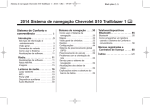
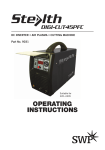
STEP 1. MOUNTING THE FRONT LEG SOCKET NEAR CAB
1a.
1b.
1c.
1d.
1e.
1f.
1g.
1h.
If installing on a 2004 Ford F-150 and newer, place the F-150 Adaptor onto the front leg socket. Install and tighten a 3/8-16 x 1” thread cutting bolt into the adaptor to make a mark on the front leg socket. Remove adapter and drill a 7/16” pilot hole and then a 1/2” hole at the indention mark of the thread cutting bolt on the leg socket. Re-install the F-150 adaptor onto the front leg socket. Do not tighten the thread cutting bolt at this time. See Figure 2.
Insert the front leg socket into the front mounting bracket as seen in Figure 1. Hold the mounting bracket flush with the top rail of the truck bed ensuring the front leg socket assembly is plumb and square to the truck bed. This may also be mounted 90 degrees.
Mark and center punch the four holes of the front mounting bracket and front leg socket foot as seen in Figure 1. NOTE: If the best mounting hole location is between floor ribs, a floor spacer and/ or two extra 5/16” flat washers have been provided to fill the void. Or rotate the Leg Socket 90° to the rear of the vehicle if possible.
Drill a pilot hole with a 7/32” drill bit in each marked hole. Then re-drill the holes with a 1/2” drill bit. Apply silicone sealant around all drilled metal holes.
Install rivnut fastener into each drilled hole. (see page 7, Figure 9 for rivnut fastener installation instructions)
Take the front leg socket assembly, four 5/16-18 x 1-1/4” hex head bolts, four 5/16” lock washers and four 5/16” flat washers and install as seen in Figure 1. Tighten all screws at this point ensuring assembly is square and plumb to the truck.
Take a 3/8 - 16 x 1” thread cutting bolt and install into the front mounting bracket as seen in Figure 1. Tighten the thread cutting bolt enough to mark the front leg socket for drilling.
Disassemble the front leg socket assembly, take the front leg socket and drill a pilot hole with a 7/32” drill bit through the mark created in the previous step by the thread cutting bolt. Then re-drill the hole with a 1/2” drill bit. Apply silicone sealant around all drilled metal holes. Reassemble the front leg socket assembly to the truck bed tightening all hardware except the 3/8-16 x 1” thread cutting blot.
Figure 1
Square the assembly
• Mark Mounting bracket holes to the bed
Ford F-150 Adaptor not shown
Center punch marks
Square the• assembly
pilot hole
3/8-16x1” thread cutting screw
to the bed• Drill 7/32 Ford
F-150 Adaptor not shown
• Re-drill with 1/2” drill bit
(Tighten the screw enough to
mark the tube for drilling)
(4 locations) 3/8-16x1” thread cutting screw
(Tighten the screw enough to
Install Rivnut Fastener
mark the tube for drilling)
(4 locations) See last
Front
page for instructions
Install Rivnut Fastener
of Bed (4 locations) See last
page for instructions
5/16-18 x 1-1/4”
Hex Head Bolt
(4 locations)
5/16” Lock Washer
(4 locations)
5/16” Flat Washer
(4 locations)
Mark the front Leg Socket hole that aligns
best on the top of a floor rib
ole that aligns
Drill
then
drill b
screw
the t
Drill 7/32” pilot hole
then re-drill with 1/2”
drill bit where the
screw market
the tube
Figure 2
Ford-150 Adaptor
Figu
Ford
3
Figure 3
Rear Leg Socket
Figur
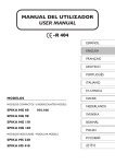
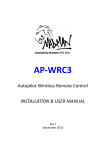
Step 2. MOUNTING THE REAR LEG SOCKET
Step 2a-g is to be used when mounting to a 90º degree tailgate stop (Most vehicles)
Plate
NOTE: Skip to Step 2h if you own a Toyota Tacoma, Chevy Colorado, or GMC Canyon
with2a 45-degree tail-gate stop.
2a.
2b.
2c.
2d.
2d.
2f.
2g.
LongX End
of Angle
Using the Hex Head 5/16-18
1” bolts,
washers, and nylon lock nuts fasten the rear mounting bracket plate Rear Mo
of end
Plate
2 Rear
1 and 2 together. The long
of the
angle on plate 2 faces away from platePlate
1. 1
Plate 1
Bracket
Insert the rear leg socketMounting
into the rear
mounting bracket assembly as seen in 3. Hold the mounting
(Plate 2
bracket assembly flush with the tailgate stop ensuring that the rear leg is plumb and square to the truck bed. (See note at bottom of page for mounting to truck bed floor)
Mark the five holes. Remove the assembly and center punch each of the holes. Drill
a 7/32”xpilot
hole, then
5/16-18
1-1/4”
re-drill each hole using a 1/2” drill bit. Apply silicone sealant around all drilled metal
holes.
Hex Head Bolt
Install rivnut fastener into each drilled hole. (see page 7, Figure 9 for rivnut fastener(4installation
instructions)
locations)
Take the rear leg socket assembly, four 5/16-18 X 1-1/4” hex head bolts, four 5/16” lock washers and four
5/16” flat washers and install as seen in Figure 3. (It may be necessary to dis-assemble
5/16” rear
Lockmounting
Washer
bracket plate 1 and 2 in order to fasten plate 2 to the truck) Tighten all fasteners at(4this
time on the rear locations)
mounting bracket.
Take a 3/8–16 X 1” thread cutting bolt and install into the rear mounting bracket as
seen Flat
in Figure
3
5/16”
Washer
Disassemble the rear leg socket assembly taking the rear leg socket and drill a 7/32”
pilot
hole
through
the
(4 locations)
mark created in the previous step with the thread cutting bolt. Then re-drill the hole using a 1/2” drill bit.
the bed
Front
Leg Socket
hole that
Reassemble the rear leg socket assembly toMark
the truck
tightening
all hardware
except the 3/8-16 x 1”
aligns
best
on
the
top
of
a
floor rib
thread cutting blot.
Now proceed to step 3.
Figure 3
Rear Leg Socket
Plate 2
Long End of Angle
of Plate 2 Rear
Mounting Bracket
Assembly Note:
Figure 4
if the best mounting hole
location is between floor
ribs, a floor spacer and
or two extra 5/16” flat
washers have been provided
to fill the void. Rotate the leg
shocket 90 degrees to the
rear of the vehicle if possible.
Plate 1
5/16-18 x 1-1/4”
Hex Head Bolt
(4 locations)
5/16” Lock Washer
(4 locations)
5/16” Flat Washer
(4 locations)
4
Mark the Front Leg Socket hole that
aligns best on the top of a floor rib
Rear Mounting
Plate 1
(Plate 2 not used)
Figure 3
Figure
Rear Leg Socket
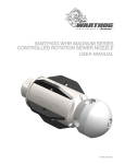
Start here for 45º degree tailgate stop.
2h.
2c.
2d.
2e.
2f.
2g.
Insert the rear leg socket into the rear mounting bracket plate 1 as seen in 4. (Plate 2 will not be used) Hold
Plate 2
the mounting bracket assembly flush with the tailgate stop ensuring that the rear leg is plumb and square
to the truck bed. (See note at bottom of page for mounting to truck bed floor)
Longthe
End
of Angle
Mark the five holes. Remove
assembly
and center punch each of the holes.
Drill
Plate
1 a 7/32” pilot hole, then Rear Moun
of
Plate
2
Rear
re-drill each hole using a 1/2” drill bit. Apply silicone sealant around all drilled metal holes.
Plate 1
Mounting Bracket
Install rivnut fastener into each drilled hole (see page 7, Figure 9 for rivnut fastener installation instructions). (Plate 2 no
Take the rear leg socket assembly, four 5/16-18 X 1-1/4” hex head bolts, four 5/16” lock washers and
four 5/16” flat washers and install as seen in Figure 4. Tighten all fasteners at this time on the
rear-mounting bracket.
5/16-18 x 1-1/4”
Take a 3/8–16 X 1” thread cutting bolt and install into the rear mounting bracket as
seen
in Figure
Hex
Head
Bolt 4.
Tighten the thread cutting bolt enough to mark the front leg socket for drilling. (4 locations)
Disassemble the rear leg socket assembly taking the rear leg socket and drill a 7/32” pilot hole through the
5/16”
Washer
mark created in the previous step with the thread cutting bolt. Then re-drill the hole
usingLock
a 1/2”
drill bit. locations)
Reassemble the rear leg socket assembly to the truck bed tightening all hardware(4
except
the 3/8-16 x 1” thread cutting blot.
5/16” Flat Washer
(4 locations)
Now proceed to step 3.
Mark the Front Leg Socket hole that
aligns best on the top of a floor rib
Figure 4
Rear Leg Socket
Rear Mounting
Plate 1
(Plate 2 not used)
Assembly Note:
if the best mounting hole
location is between floor
ribs, a floor spacer and
or two extra 5/16” flat
washers have been provided
to fill the void. Rotate the leg
shocket 90 degrees to the
rear of the vehicle if possible.
-1/4”
Bolt
ns)
5/16-18 x 1-1/4”
Hex Head Bolt
(4 locations)
Washer
ns)
5/16” Lock Washer
(4 locations)
Washer
ns)
5/16” Flat Washer
(4 locations)
5
STEP 3. INSTALLING THE FRONT UPRIGHT
3a.
3b.
3c.
3d.
Take one upright and insert into the front leg socket assembly. Tighten the 3/8 - 16 x 1” thread cutting screw installed in step 1f. in the front mounting bracket.
Take one extension and insert it into the upright as seen in Figure 6. After tighten at the desired location, seal the joint between the two tubes with the provided silicone sealant.
Take the ladder stop, one 3/8 - 16 x 3/4”
carriage bolt, one 3/8” flat washer and one
3/8 - 16 nylon lock nut and install onto the
upright as seen in Figure 6.
Take the one strap and install it onto the bracket as seen in Figure 6.
Figure 6
Install the
Figure
6Ladder Stop
on the extension
Install the Ladder Stop
the extension
3/8-16x3/4”on
Thread
Cutting Screw
(Locks3/8-16x3/4”
the extension
Thread
to theCutting
leg) Screw
(Locks the extension
to the leg)
3/8-16 x 3-3/4”
Carriage Bolt
3/8-16 x 3-3/4”
Carriage Bolt
3/8” Flat Washer
3/8”
Flat Washe
3/8-16
Nylon
Lock Nut
3/8-16 Nylon
Lock Nut
Adjust extension to prevent
side motion of the ladder
Adjust extension to prevent
side motion of the ladder
STEP 4. INSTALLING THE REAR UPRIGHT
4a.
4b.
4c.
Take the remaining upright and insert into the rear leg socket assembly. Tighten the 3/8 - 16 x 1” thread
cutting screw installed in step 2f. in the rear mounting bracket.
Take the remaining extension and insert it into the upright as seen in Figure 6. After tighten at
the desired location, seal the joint between the two tubes with the provided silicone sealant.
Take the remaining ladder strap and install it onto the bracket as seen in Figure 6.
Figure 7
Figure 7
STEP 5. SECURING A LADDER TO THE RACK
5a.
5b.
6
Carefully place a ladder on the rack, and check door entry and head clearance. If clearance is ample, and
if desired, the uprights may be shortened as long as a minimum of 2” above the cab roof is maintained, see Figure 7. Remove and cut the uprights if desired. Note that you need to cut from the bottom of the upright. Double check the measurement before cutting.
Secure ladder with the provided ladder straps when transporting. Secure or remove ladder straps when
not being used.
Secure ladder with
Velcro Ladder Strap
Secure ladder with
Velcro Ladder Strap
2” Min
2” Min
Lock Nut
nt
Figure 8
Rope Cleat
STEP 6. INSTALLATION OF ROPE
CLEATS (optional)
Apply sealant around
holes before assembling
The two rope cleats are to be mounted
where desired. Apply silicone sealant
around all drilled metal holes.
See right for installation procedure.
er
ladder with
Ladder Strap
#10-24 Flat Washer (2)
#10-24 x 2-3/4”
Machine Screw (2)
#10-24 Nylon Lock
Nut (2)
2” Min
Figure 8
Figurearound
8
Apply sealant
Rope Cleat
holes before assembling
Apply sealant around
holes before assembling
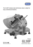
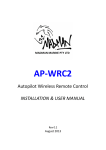
FIGURE 9: RIVNUT FASTENER
INSTALLATION
#10-24 Flat Washer (2)
Note: Make sure there is enough hole depth
before installing the
RivnutFlat
fastener.
#10-24
Washer (2)
Note: Black Oxide Bolt, Flat Washer, and Installation
#10-24 Nylon Lock
Tool are only used to install Rivnut fastener.
Nut (2)
#10-24 Nylon Lock
• Place a drop of oil on theNut
black
(2)oxide bolt for lubrication.
• Insert Rivnut fastener in the hole.
• Hold the “Installation Tool” with a 9/16” wrench while turning the “Black Oxide Bolt” with a 1/2” wrench until fully seated.
• Make sure the rivnut fastener and installation tool do not turn while tightening.
• Turning “Black Oxide Bolt” will be hard until fastener “bulbs” out.
• When Rivnut fastener is fully seated, remove the black oxide bolt and washer and continue with the installation.
Rope Cleat
Figure 9
#10-24 x 2-3/4”
Black Oxide
Bolt
Machine
Screw
(2)
#10-24 x 2-3/4”
Machine
Screw (2)
Flat
Washer
9/16” Wrench
Installation Tool
Rivnut Fastener
7
TIE DOWN ENGINEERING GENERAL PRODUCT LINE LIMITED WARRANTY
Limited Warranty TIE DOWN ENGINEERING Inc (“TIE DOWN") warrants its products to be free from defects in material and workmanship for one
year from date of delivery to the original purchaser when properly installed, used and maintained by the purchaser.
This warranty does not apply to damage or loss caused by any or all of the following circumstances or conditions:
• Damage caused during installation.
• Parts, accessories, materials or components used with or replacing any TIE DOWN braking system not obtained from or approved in
writing by TIE DOWN.
• Misapplication, misuse and failure to follow the directions or observe cautions and warnings on installation,operation, application,
inspection or maintenance specified in any TIE DOWN quotation, acknowledgement, sales literature, specification sheet or installation
instruction and service manual ("applicable literature").
• Use of product in any other application other than those described in TIE DOWN’s product information materials.
If any TIE DOWN products are found upon TIE DOWN's examination to have been defective when supplied, TIE DOWN will either: credit the
purchaser's account for the purchase price of the TIE DOWN product; replace the TIE DOWN product; or repair the product. TIE DOWN has sole
discretion in choosing which option to provide. For this LIMITED WARRANTY to apply, TIE DOWN must receive notice of the alleged defect within 30
days of either the discovery of the alleged defect or the expiration of the warranty period, whichever is earlier. Any claim not made within this
period shall conclusively be deemed waived.
If requested by TIE DOWN, purchaser shall return the alleged defective product to TIE DOWN for examination at purchasers expense. TIE DOWN will
not pay for expenses incurred in returning a product to TIE DOWN without TIE DOWN's prior written authority. TIE DOWN shall not be liable for any
other expenses purchaser incurs to remedy any defect. Purchasers waive subrogation on all claims under any insurance.
Limitation of Liability: It is expressly agreed that the liability of TIE DOWN is limited and TIE DOWN does not function as an insurer. THE REMEDIES
SET FORTH IN THIS WARRANTY SHALL CONSTITUTE THE EXCLUSIVE REMEDIES AVAILABLE TO THE PURCHASER OR USER AND ARE IN LIEU OF ALL
OTHER REMEDIES, EXPRESS OR IMPLIED. THE LIABILITY OF TIE DOWN, WHETHER IN CONTRACT, IN TORT, UNDER ANY WARRANTY OR OTHERWISE,
SHALL NOT EXCEED THE PURCHASE PRICE OF THE PARTICULAR PRODUCT MANUFACTURED, SOLD OR SUPPLIED BY TIE DOWN.
To Obtain Technical Assistance: To enable TIE DOWN to respond to a request for assistance or evaluation of customer or user operating difficulty,
please provide at a minimum the following information by calling 404-344-0000:
• Model number, serial number and all other data on the specific component which appears to be involved in the difficulty.
• The date and from whom you purchased your TIE DOWN product.
• State your difficulty, being sure to mention at least the following: Application, Nature of load involved, and Weight of the load.
Field Service: If field service at the request of the purchaser is rendered and the difficulty is found not to be with TIE DOWN's product, the
purchaser shall pay the time and expense (at the prevailing rate at the time of service) of seller's field representative(s). Charges for service, labor
and other expenses that have been incurred by the purchaser, its customer or agent without prior written authorization of TIE DOWN will not be
accepted.
TIE DOWN EXTENDS NO WARRANTY, EXPRESS OR IMPLIED, ON PRODUCTS NOT MANUFACTURED BY TIE DOWN OR TO TIE DOWN'S DESIGN
SPECIFICATION, INCLUDING BUT NOT LIMITED TO SUCH ITEMS AS NON-TIE DOWN TIRES, BRAKES, ACTUATORS, BEARINGS, HOSE AND TUBING.
PURCHASER'S RECOURSE SHALL BE LIMITED TO ANY WARRANTY OF THE RESPECTIVE MANUFACTURERS.
THIS WARRANTY EXCLUDES ALL IMPLIED WARRANTIES OF MERCHANTABILITY OR FITNESS FOR A PARTICULAR PURPOSE OR ANY PURPOSE.
THIS WARRANTY DOES NOT COVER NOR EXTEND TO INCIDENTAL OR CONSEQUENTIAL DAMAGE. Some states do not allow the exclusion or limitation
of incidental or consequential damages, so the above limitation or exclusion may not apply to you. This warranty gives you specific legal rights,
and you may also have other rights which vary from state to state.
No representative has authority to make any representation, promise or agreement except as stated in this Limited Warranty. TIE DOWN reserves
the right to make design and other changes upon its products without any obligation to install the same on any previously sold or delivered
products.
DUE TO THE WIDE VARIATION IN USES TO WHICH TIE DOWN PRODUCTS (WHEELS, HUBS, BRAKES, ETC.) ARE SUBJECTED BY USERS, WE ARE UNABLE
TO SPECIFY CARRYING CAPACITIES OR SPEEDS FOR A PARTICULAR APPLICATION. THEREFORE, THE MANUFACTURER MUST TEST HIS EQUIPMENT
UNDER THE MOST SEVERE CONDITIONS TO DETERMINE THAT TIE DOWN PRODUCTS ARE SUITABLE.
102113,E1346
THERE ARE NO WARRANTIES WHICH EXTEND BEYOND THOSE DESCRIBED ABOVE. EFFECTIVE JANUARY 2003 THIS WARRANTY SUPERSEDES ALL
PRIOR WARRANTIES, WRITTEN OR IMPLIED.