1
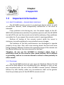
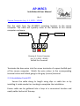
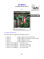
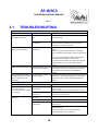
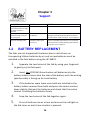
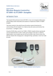
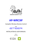
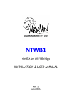
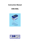
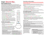
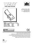
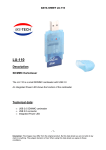
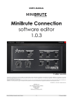
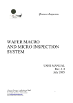
AP-WRC3 Autopilot Wireless Remote Control INSTALLATION & USER MANUAL Rev 1 December 2014 AP-WRC3 Installation & User Manual Rev 1 Table of Contents 1.1 Overview.............................................................................................2 1.2 Specifications......................................................................................3 1.3 Important Information........................................................................4 1.3.1SAFETY WARNING – PLEASE READ CAREFULLY...............................................4 1.3.2DISCLAIMER ..........................................................................................................4 2 Installation.........................................................................5 2.1 Base Unit Installation..........................................................................5 2.1.1OVERVIEW ............................................................................................................5 2.1.2ANTENNA ATTACHMENT...........................................................................................5 2.1.3MOUNTING LOCATION.............................................................................................6 2.2 Electrical Installation...........................................................................7 2.2.1CABLE ROUTE CONSIDERATIONS.................................................................................7 2.2.2ELECTRICAL COLOUR CODE.......................................................................................7 2.2.3ELECTRICAL CONNECTIONS........................................................................................7 2.2.4INSTALLATION FINISH OFF.........................................................................................9 2.3 INITIAL FOB TESTING.........................................................................10 2.4 OPERATION.......................................................................................12 2.4.1GENERAL............................................................................................................12 2.4.2STANDBY MODE SELECTION ENABLE/DISABLE.............................................................12 2.4.3BUTTON ASSIGNMENTS..........................................................................................13 2.4.4CHANGING MODE................................................................................................14 2.4.5CHANGING COURSE...............................................................................................14 3 Support............................................................................15 3.1 TROUBLESHOOTING..........................................................................15 3.2 BATTERY REPLACEMENT ..................................................................16 3.3 SALES & SUPPORT.............................................................................17 SeaTalk is a registered trademark of Raymarine UK Ltd. Contents of this handbook © Madman Marine Pty Ltd 1 AP-WRC3 Installation & User Manual Rev 1 1.1 Overview Illustration 2: Package contents. 2 x Fobs (Transmitters) 1 x 433MHz Antenna, AP-WRC3 Base Unit 3m cable Illustration 1: What's in the box - AP-WRC3 parts identification. Your Madman Marine remote control provides wireless control of Raymarine autopilots with SeaTalk. It has been designed for owner installation and is ready for use after making 3 electrical connections to the existing autopilot. The AP-WRC3 additionally requires batteries to be installed in the fobs. The remote control is ideal for single-handed or short-handed crews to be able to steer from the front of the boat (for example when changing sails or setting/retrieving a spinnaker) or even from inside the cabin. 2 AP-WRC3 Installation & User Manual Rev 1 1.2 Specifications The system consists of a base unit which houses a microcontroller and electronics for communicating with the autopilot, a 433MHz antenna, two (2) remote control fobs (transmitters) and 3m of cable. AP-WRC3 Electrical Supply Voltage 6.5 to 15Vdc Operating Current < 80mA Internal Fuse Type Automatically resetting IP Rating Base unit: 20 Fob: 67 Transmitter Range 50m (line of sight) Transmitter Frequency 433Mhz Transmitter Battery 2 x CR2016 lithium in each fob (user replaceable) Cable Length/Conductor Size 3m/0.5mm2 Note: The supplied cable is already terminated at the AP-WRC3 base unit. The free end has bare wires prepared for termination in screw terminals. Specifications may change without notice. 3 Chapter 3 Support15 1.3 Important Information 1.3.1 SAFETY WARNING – PLEASE READ CAREFULLY The AP-WRC3 remote control is an electronic device which, as with all electronic devices, could unexpectedly malfunction or not work as intended. If any problems arise during use, turn the power supply to the APWRC3 off and determine whether the problem persists with the AP-WRC3 turned off. Do not use the remote control while underway if any problems are evident or if you suspect the remote control is causing problems. Perform all testing of the remote control while the vessel is stationary to avoid unplanned or uncontrolled course changes. The batteries of the fob could become too discharged to operate properly at any time. Also, with crew moving about the boat and items being stowed in different locations the operating range of the remote can be affected differently from one moment to the next. Therefore, do not use the AP-WRC3 in situations where there is insufficient room for the vessel to alter course without risk of collision or grounding, such as in a narrow channel or when in close proximity to other vessels. 1.3.2 Disclaimer Use the AP-WRC3 entirely at your own risk. Madman Marine Pty Ltd will not be held liable for any consequential loss, damage or injury in any way connected with the use of the AP-WRC3 remote control. Madman Marine Pty Ltd’s liability under any circumstances shall not be greater than the purchase price of the AP-WRC3 remote control. 4 AP-WRC3 Installation & User Manual Rev 1 2 Installation 2.1 Base Unit Installation 2.1.1 Overview The AP-WRC3 base unit must be mounted to a flat surface inside the boat’s cabin where it will be protected from water and mechanical damage. The base unit does not need to be in direct line of sight of the fobs so can be hidden out of view if desired, however the fewer obstructions between the base unit fob the better the reception performance. Ideally only the deck will be between the base unit and the most distant location from which the fob will be used (usually the bow). If more than one bulkhead (or other obstruction) in addition to the deck is in the path between the most distant location from which the ifob will be used and the base unit then operation may be unreliable. Refer to Drawing 1 (opposite) for preferred mounting orientation details. The drawing shows the AP-WRC3 mounted on a flat vertical surface which runs fore and aft. The back of the enclosure faces outboard while the bottom faces the cabin sole. 2.1.2 Antenna Attachment Screw the antenna to the gold coloured connector at the top-right of the base unit. Once the base unit has been mounted, the antenna can be adjusted by rotating or bending to almost any desired position. Ideally the antenna will be positioned in a vertical alignment for best performance. Avoid positioning the antenna in a horizontal alignment otherwise performance may suffer. 5 Chapter 2 Installation 2.1.3 Mounting Location The following must be taken into account when selecting a suitable mounting location: • Ability to view the LED indicators, • Obstructions between base unit and furthest point of use, • Protection from water (including condensation) and mechanical damage, • Proximity to equipment or cabling which called cause interference to or be interfered by the AP-WRC3. There are two flanges on the base unit enclosure which have holes provided for mounting to any flat surface with screws (2 required). Antenna positioned in vertical alignment Outboard Mounting screw (one each side) Inboard Drawing 1: Preferred mounting orientation. 6 AP-WRC3 Installation & User Manual Rev 1 2.2 Electrical Installation 2.2.1 Cable Route Considerations Although the supplied cable has screened (shielded) conductors to reduce the effects of interference from electromagnetic noise (EMI), care should still be taken in selecting the route the cable of the AP-WRC3 is to take. The cable should be kept as far as possible from the following items: • radio transmitters and associated antennas and antenna cables, • fluorescent lights, • electrical cables carrying AC current, • engines including outboard motors • AC powered electrical equipment Also avoid routing the cable near compasses or other sensitive instruments to avoid interference from the AP-WRC3. 2.2.2 Electrical Colour Code The colour coding of the 3 cores of the AP-WRC3 cable is as follows: Red +12Vdc Black 0Vdc Yellow SeaTalk data 2.2.3 Electrical Connections The connection method differs depending on the model autopilot to be connected. Refer to the specific instructions for the particular types of autopilot. 7 Chapter 2 Installation ST1000+ and ST2000+ Run the cable from the AP-WRC3 mounting location to the rear of the autopilot bulkhead connector. Terminate the bare wires in the terminals of the bulkhead connector as shown in Drawing 2 3 Black (2) Red (1) 2 4 1 5 Keyway Yellow (4) 6 Drawing 2: Rear of ST1000+ / ST2000+ Bulkhead Socket ST4000+ Run the cable from the AP-WRC3 mounting location to the rear of the ST4000+ controller/display. Crimp or solder the bare wires into small spade terminals (refer Illustration 3) and then push the spade terminals onto the pins of the ST4000+ SeaTalk port pins. Black Yellow Red OR Black Yellow Red Drawing 3: ST4000+ SeaTalk Port 8 Illustration 3: 3 x Spade Terminals Required AP-WRC3 Installation & User Manual Rev 1 Course Computer (e.g. S-1, SPX5 - SPX30) Run the cable from the AP-WRC3 mounting location to the course computer. The cable will typically enter at the bottom of the course computer enclosure. Black Red Yellow Drawing 4: Course Computer (e.g. S-1, SPX5 - SPX30) SeaTalk Port Terminals Terminate the bare wires into the screw terminals of a spare SeaTalk port of the course computer. Match the wire colour to the corresponding terminal colour with black going to the grey (screen) terminal. 2.2.4 Installation Finish Off Secure the cable along its length using clips or cable ties or by installing it inside conduit or trunking to complete the installation. Excess cable can be gathered into a loop at a convenient location and neatly cable tied out of the way. 9 Chapter 2 Installation 2.3 INITIAL FOB TESTING 1. Check that the fobs have two batteries installed in each one by pressing any button and verifying that the red light on the fob turns on. If not, install new CR2016 lithium batteries before proceeding further. (Refer to section 3.2 for battery replacement instructions) 2. Confirm the autopilot has power to it by checking that the display is on and displaying a value. Test the autopilot operates as per normal from the autopilot’s own buttons by first pressing the ‘Auto’ key and then pressing the course change buttons to alter position by 1 and 10 degrees to both port and starboard. Do not proceed until you are satisfied the autopilot is operating normally. 3. Switch on power to the AP-WRC3. Watch for the blue LED indicator on the AP-WRC3 to flash 3 times indicating start up. (If the LED does not flash after turning power on, refer to the troubleshooting section). 4. Press each button on each fob and verify that the blue LED indicator on the AP-WRC3 turns on briefly with each button press. (If the LED does not turn on for any button presses, refer to the troubleshooting section). 5. Press the ‘Auto’ button on the autopilot to select Auto mode (for ST1000/ST2000+ a letter ‘A’ appears next to the value on the autopilot display). 6. Press Button A (or B) on one of the AP-WRC3 fobs and verify that the number displayed on the autopilot changes by 1. (Note: the autopilot may not move with only a 1 degree course change). 10 AP-WRC3 Installation & User Manual Rev 1 7. Press Button C (or D) on the AP-WRC3 fob and verify that the number displayed on the autopilot changes by 10. 8. Press the ‘Standby’ button on the autopilot to select Standby mode (for ST1000/ST2000+ a flashing letter ‘C’ appears next to the value on the autopilot display). 9. Press and hold (for at least 1.5 seconds) Button A on the AP-WRC3 fob and verify that the autopilot changes to Auto mode (for ST1000/ST2000+ a letter ‘A’ appears next to the value on the autopilot’s display). 10. (Optional, with 'Standby' enabled) Press and hold (for at least 1.5 seconds) Button B on the AP-WRC3 fob and verify that the autopilot changes to Standby mode (for ST1000/ST2000+ a flashing letter ‘C’ appears next to the value on the autopilot’s display). If all of the above checks work then the AP-WRC3 is ready to use with the fobs. Blue LED Indicator – Fob Button Operation Illustration 4: AP-WRC3 Button Press LED Indicator 11 Chapter 2 Installation 2.4 OPERATION 2.4.1 General The fob (transmitter) buttons replicate the functions available from the autopilot to provide the same course changing and auto-tacking functionality. In addition, the autopilot mode can be changed between Standby, Auto, Wind Vane and Track from the fob. A red light on the fob indicates when a button is being pressed. A blue light on the base unit turns on to acknowledge each button press. When pressing a button hold the button down for about half a second. A button press which is too short will be ignored and a button press which is too long may cause an undesired mode change. A bit of experimentation will allow you to get to know the required button press durations. 2.4.2 Standby Mode Selection Enable/Disable The AP-WRC3 ships with the ability to select Standby mode from Button B disabled by default. To enable the ability to select Standby mode from Button B a DIP switch inside the base unit must be turned 'On'. To access the DIP switch, remove the 4 screws from the back of the base unit and remove the cover. Locate the DIP switch as shown in Illustration 5 and using a small screwdriver or similar move the DIP switch to the desired position: • 'ON' = Standby mode is enabled and can be selected using a long press of Button B • 'OFF' = Standby mode is disabled from Button B. 12 AP-WRC3 Installation & User Manual Rev 1 DIP Switch Illustration 5: Standby Enable/Disable DIP Switch inside base unit. 2.4.3 Button Assignments The fob buttons are assigned the following functions: Button A change 1 degree to port / select Auto Button B change 1 degree to starboard / select Standby Button C change 10 degrees to port Button D change 10 degrees to starboard Buttons A & C (together) auto-tack to port Buttons B & D (together) auto-tack to starboard Buttons A & B (together) select Wind Vane mode Buttons C & D (together) select Track mode 13 Chapter 2 Installation 2.4.4 Changing Mode The buttons are assigned the following mode change functions: Long Press Button A select 'Auto’ mode Long Press Button B select ‘Standby’ mode (if enabled) *Buttons A & B select ‘Wind Vane’ mode# *Buttons C & D select ‘Track’ mode * Must be in ‘Auto’ mode first. # Wind Vane mode only available if valid wind data is being received by the autopilot. 2.4.5 Changing Course Press each button (or combination of buttons) briefly when wanting to change course by 1 or 10 degrees or to auto-tack. To auto-tack it is acceptable to (for example) press and hold Button A first and then press Button C – the two buttons do not need to be pressed at exactly the same time but the second button needs to be pressed quickly after pressing the first button to prevent undesired course changes. For long button presses (changing to Auto or Standby) hold the button(s) pressed for at least 1.5 seconds. (see section 2.4.2. to disable Standby mode if necessary). Important Notes: • Do not hold Button A (or B) for longer than one second before pressing Button C (or D) due to the mode change functions of Buttons A and B when held for 1.5 seconds. • Pressing Button C or Button D first in a multi-button press may cause a 10 degree course change if the second button is not pressed immediately. • Do not press the A or B buttons repeatedly in quick succession as this may be registered as a single long button press resulting in an unexpected mode change! Allow at least half a second between button presses. 14 AP-WRC3 Installation & User Manual Rev 1 3 Support 3.1 TROUBLESHOOTING GENERAL SYMPTOM CAUSE REMEDY Autopilot does not respond to fob button presses. Autopilot is not turned on. Check that the Autopilot display is on (meaning it has power to it). SeaTalk data not connected Confirm that the SeaTalk data wire is connected properly (refer to installation section) and the connection is free from corrosion. Check that power is being supplied to the APWRC3. Watch to see that the blue LED of the AP-WRC3 base unit flashes 3 times when power is first turned on. Press any of the fob buttons while observing the blue LED of the AP-WRC3. If the blue LED illuminates when buttons are pressed then the APWRC3 has power and is responding to button presses. The autopilot must be receiving valid wind data before Wind mode can be selected. Connect wind instruments to the autopilot using NMEA or SeaTalk. On occasions when the Autopilot is completing a movement in Auto mode it will ignore commands from SeaTalk. This is not a problem with the APWRC3. The blue LEDs does not flash on the AP-WRC3 AP-WRC3 does not have power to it. Cannot select Wind Mode No wind instruments connected to autopilot Everything works but sometimes button presses do not register with the Autopilot Autopilot is finishing a course change FOB OPERATION SYMPTOM Blue LED on the AP-WRC3 base unit does not illuminate when fob buttons are pressed. One or more fob buttons do not work. CAUSE REMEDY The fob (transmitter) is not working Refer to “Red light on fob…” section below if no buttons work. Replace batteries if any of the buttons do not work. Check that any main switch for the 12V supply to the base unit is turned on. Replace batteries in fob (2 x CR2016) The base unit is not turned on. Fob batteries are drained. Faulty fob. Fob signal weak or obstructed. Replace fob. Replace the batteries if the range of the fob has deteriorated. If possible, remove obstructions between the fob and the base unit. Check for for sources of radio interference. Relocate the base unit if necessary. 15 Chapter 3 Support SYMPTOM CAUSE REMEDY Red light on fob (transmitter) does not light up when a button is pressed. Standby mode not selected when Button B is pressed for a long time. Autopilot unexpectedly goes into Standby mode Fob batteries are dead Replace batteries in fob (2 x CR2016) Button B Standby mode is disabled. Enable Standby mode selection from Button B by moving the Standby Enable/Disable DIP switch to the 'On' position. Refer to section 2.4.2 on page 12. Allow at least half a second between button presses. If Standby mode selection is not required from the fob then disable Standby mode selection – see section 2.4.2 on page 12. 3.2 Button B being pressed multiple times in quick succession. BATTERY REPLACEMENT The fobs are not shipped with batteries due to restrictions on transporting lithium batteries by air and so new batteries must be installed in the fobs before using the AP-WRC3. 1. Separate the two halves of the fob by using your fingernail to gently pry the fob apart. 2. Insert two CR2016 lithium button cell batteries into the battery holder. Ensure that the side of the battery with the writing (positive side) is facing up for each battery. 3. If the batteries seem loose once both are installed in the battery holder remove them both and press the centre contact down slightly. Reinsert the batteries and check that the centre contact is holding the batteries firmly. 4. 5. Snap the two halves of the fob together again. Press all buttons one at a time and ensure the red light on the fob turns on each time a button is pressed. 16 AP-WRC3 Installation & User Manual Rev 1 3.3 SALES & SUPPORT For all sales and support enquiries, contact: Neil Finlayson Madman Marine Pty Ltd. Ph. 0412 MAD MAN (+61 412 623 626) E. [email protected] W. www.madmanmarine.com 17