1
US007356384B2
(12) United States Patent
(10) Patent N0.:
Gull et a].
(54)
(45) Date of Patent:
LOAD MANAGEMENT SYSTEM
(56)
US. PATENT DOCUMENTS
Wesley C- sodemalfm Dousman; WI
(Us); Kenny J- stalr, NOITh Pral?es WI
4,066,913 A *
4,075,699 A
l/l978 Manning et a1. ............ .. 307/38
2/l978 Schneider et al.
(US)
4,324,987 A *
4/1982
Sullivan et a1. ............. .. 307/35
4,349,879 A
9/1982
Peddie et a1.
.
,
_
(73) Ass1gnee: Briggs & Stratton Corporation,
4,499,385 A
Wauwatosa, WI (US)
_
Not1ce:
_
_
Filedi
_
(Contmued)
W0
FOREIGN PATENT DOCUMENTS
WO 01/37392
5/2001
OTHER PUBLICATIONS
Jlll- 13, 2005
Prior Publication Data
Us 2006/0018069 A1
21985 Slavik
_
_
Subject to any disclalmer, the term of this
patent is extended or adjusted under 35
U-S-C- 154(1)) by 37 days-
(21) Appl- No: 11/180,228
(22)
(65)
Apr. 8, 2008
References Cited
(75) Inventors: Philip Gull, New Berlin, WI (US);
(*)
US 7,356,384 B2
Intellitec SMART EMS Installation and Service Manual, (P/N
53-204mm’ Oct' 10’ 1997'
C t'
d
( Onmue )
Jan. 26, 2006
.
.
Primary ExamineriZoila Cabrera
(63)
Related U's' Apphcatlon Data
Continuation-in-part of application No. ll/086,l67,
Assistant ExamineriNate Laughlin
(74) Attorney, Agent, or FirmiMichael Best & Friedrich
?led on Mar. 22, 2005.
LLP
(60)
Provisional application No. 60/ 676,392, ?led on Apr.
(51)
(52)
(58)
29, 2005, provisional application No. 60/588,073,
(57)
?led on Jul‘ 15’ 2004'
Int. Cl.
G05D 11/00
(2006.01)
G05D 17/00
(2006.01)
G05D 3/12
(2006.01)
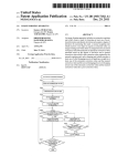
A method, and a system that uses the method, of managing
loads for residential use. The method includes connecting a
?rst signal-responsive switch to a ?rst load, and connecting
a second signal-responsive switch to a second load that has
a lower priority than the ?rst load. The method also includes
ABSTRACT
G05D 5/00
G05D 9/00
(2006.01)
(2006.01)
sensing ?rst and second electrical signals from the respec
tive ?rst and second loads, and ensuring the ?rst signal
GOSD 23/00
(2006.01)
responsive switch is in a CLOSED state and the second
US. Cl. .................... .. 700/295; 700/286; 700/276;
signal-responsive switch in an OPEN state after both a
700/300
combination of the sensed ?rst and second electrical signals
Field of Classi?cation Search .............. .. 700/295,
exceeds a ?rst threshold value and the sensed ?rst electrical
700/287, 286, 22, 28, 31, 276, 278; 307/39;
361/90, 1
See application ?le for complete search history.
signal is below a second threshold value.
11 Claims, 11 Drawing Sheets
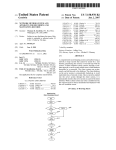
ncmnsm
ID
"4w:
170 A
172
178
192
190
160
144
anvil
US 7,356,384 B2
Page 2
US. PATENT DOCUMENTS
7,119,457 B1*
2001/0030468 A1
4,617,472
4,620,283
4,695,991
4,916,328
5,422,517
5,923,830
6,172,432
6,487,509
6,507,164
6,510,369
6,590,304
6,633,802
6,652,330
7,010,363
7,015,599
A
A
A
A
A
10/1986
10/1986
9/1987
4/1990
6/1995
7/1999
1/2001
11/2002
1/2003
1/2003
7/2003
10/2003
11/2003
3/2006
3/2006
Slavik
2002/0024332 A1*
2005/0107892 A1*
Butt et a1.
10/2006
Flegel ....................... .. 307/64
10/2001 Anderson et al.
2/2002
5/2005
Gardner ................ .. 324/103 R
Matsui et al. ............... .. 700/28
Hudson
OTHER PUBLICATIONS
Culp, III
Verney et al.
Fuchs et a1.
Schnackenberg et al.
Aisa
............... ..
307/23
..
702/62
Healey et al.
2003.
Lacy
Intellitec Energy Management Unit 2 (EMU2) Service Manual,
Manning et al.
(P/N 53-22083A100), at least as early as Mar. 22, 2003.
Generac Power Systems, Inc., PoWerMaster Technical Manual, 16
Sodoski et al.
Wasilewski
Donnelly et al.
Gull et al.
Intellitec 50 AMP Smart Energy Management System Installation
and Service Manual, (P/N 5300684B00), Mar. 1, 2000.
Intellitec PoWerline Energy Management System Installation and
Service Manual, (P/N 5322100A100), at least as early as Mar. 22,
........... .. 700/19
pages, dated Apr. 7, 2006.
* cited by examiner
U.S. Patent
Apr. 8, 2008
Sheet 1 0f 11
US 7,356,384 B2
FIG.1
U.S. Patent
Apr. 8, 2008
Sheet 2 0f 11
US 7,356,384 B2
5:upmuDt?aOw)mz
520.4350
@w2a8s5
.m43a25n:
N.0E
wt
N2.
09.
U.S. Patent
Apr. 8, 2008
Sheet 3 0f 11
US 7,356,384 B2
U.S. Patent
Apr. 8, 2008
US 7,356,384 B2
Sheet 5 0f 11
Start
I
BB
+
60
Utility Present
4
G5
Turn on Green
LED
+
i2 /
608
612
Utility drops below
Contactor in Utility
7
position
70% of 240 volts
'
Turn Off Green
LED
jumper set for
generator warm up?
520
624
r
Generator warm
Generator warm
up time 20
seconds
up time 50
seconds
I
628
Is the fuel
switch in LP?
640
s the Gen.
5 the Gen.
rating switch in
rating switch in
12kW?
15kW?
646
644
Generator rated 50
amp
Generator rated
625 amp
Generator rated '2?
amp
660
s the Gen.
s the Gen.
rating switch in
rating switch in
12kW?
1 5kW?
No
668
664
, /
Generator rated 40
amp
FIG. 6
Generator rated 50
amp
Generator rated 7?
amp
U.S. Patent
Apr. 8, 2008
Sheet 6 0f 11
US 7,356,384 B2
680
is the
Generator
Did the Utility
voltage return above
0% of 240 volts?
676
Wait warm up time
Yes
before transferring
to Generator
/ 688
V
684
Did the Utility
voltage return above
Turn On Green
LED
Yes
/ 689
0% of 240 volts’?
10 second time
delay to detennine
692
if Utility is stable
Is the
generator
690
is 10 second
ime delay done?
Is the
Generator
700
701
Open Relays A 8.
B for 5 minutes
Turn On Red LED
Yes
Is the
generator
708
/ 702
Relays A & B to
stay open
Contactor to stay
on Utility
v
‘
Transfer contactor
to Generator
‘
i
116
Contactor to stay
on Generator for
minimum of 5
minutes
FIG. 6a
No
U.S. Patent
Apr. 8,2008
Sheet 7 or 11
US 7,356,384 B2
5 minute time
period done?
Yes
728
724
tility > 80% 0
240 volts?
736
Open Relays A &
5
732
Wait 10 seconds
for Utility to
stabilize. Turn on
Green LED
/ 760
Wait 5 seconds
764
Open Relays A &
No
B for 5 minutes
5 second time
delay done?
/ 74B
/ 768
Transfer contactor
to Utilityv Turn Off
Red LED when
Generator voltage
Close Relay 5
< 80%
772
752
5 minute time
Reset current
period done?
values of Relays A
& B to zero
756
Close Relay A
FIG. 6b
Yes
U.S. Patent
Apr. 8, 2008
Sheet 8 0f 11
US 7,356,384 B2
776
5 minute time
period done?
No
=0
Close Relay A
796
Is the load >
NO
85% rated
B08
Wait 5 seconds for
load to stabilize
804
Yes
Open Relay A and
record current
(Difference from
closed to open)
FIG. 6c
U.S. Patent
Apr. 8, 2008
B16
current
difference < 5
Sheet 9 0f 11
/ 820
Yes
amps?
Assign previous
value to Relay A
No
/ 824
Wait 5 minutes to
close Relay A
FIG. 6d
US 7,356,384 B2
U.S. Patent
Apr. 8, 2008
US 7,356,384 B2
Sheet 10 0f 11
828
1st time
Wait 5 seconds for ‘
through?
load to stabilize
. 854
5 sec time
5 min time
delay done?
865
delay done?
Reiay A
closed?
cad <= 85 .
rated - Relay
B’?
Yes
Close Reiay B
Is Relay A
closed?
550
880
load > 85%
rated?
i start & be <~
85%?
Actual-B) + -
No
' start & be <
NO
load > rated?
558
7
Open Relay B a
Wait 5 seconds for
load to stabilize
nd // 896
record current
(Difference from
closed to open)
current
difference < 5
amps?
Assign previous
value to Relay B
Wait 5 minutes to
close Relay B
FIG. 69
U.S. Patent
Apr. 8, 2008
Sheet 11 0f 11
US 7,356,384 B2
948
Yes
ls the NC
called to start?
912
load > 85%
M
rated?
l F l
V
916
N0
940
load > rated’?
l
Wait 5 seconds for
load to stabilize
Open Relay 8 and
924
racord current /
(Dlffere noe from
closed to open)
944
/ 932
928
5 sec time
delay done?
current
Yes
difference < 5
Assign previous
value to Relay B
amps?
N0
936
‘
Q
Wa1t5 rmnutes to
U
close Relay B
FIG. 6f
US 7,356,384 B2
I
2
LOAD MANAGEMENT SYSTEM
second signal-responsive sWitches that are connected to
respective ?rst and second loads, a sensor that senses ?rst
RELATED APPLICATIONS
and second electrical signals from the respective ?rst and
second loads, and a controller. The ?rst signal-responsive
sWitch has a ?rst priority; and the second signal-responsive
This application claims the bene?t of US. Provisional
Patent Application No. 60/588,073, ?led on Jul. 15, 2004,
and US. Provisional Patent Application No. 60/676,392
?led on Apr. 29, 2005; and is a continuation-in-part of US.
patent application Ser. No. 11/086,167, ?led on Mar. 22,
2005, entitled “Residential Load PoWer Management Sys
tem”, and assigned to the assignee of this application, all of
Which applications are incorporated by reference herein.
sWitch has a second priority that is loWer than the ?rst
priority. The controller ensures that the ?rst signal-respon
sive sWitch is in a CLOSED state and the second signal
responsive sWitch is in an OPEN state after the sensor has
sensed that a combination of the ?rst and second electrical
particularly, to residential poWer management.
signals exceeds a ?rst threshold value and that the ?rst
electrical signal is beloW a second threshold value.
In another form, the invention provides a method of
managing loads for residential use. The method includes
connecting a ?rst signal-responsive sWitch to a ?rst load, and
connecting a second signal-responsive sWitch to a second
load that has a loWer priority than the ?rst load. The method
When there is a residential poWer outage, back up poWer
may be provided by a standby generator. In some cases, the
also includes sensing ?rst and second electrical signals from
the respective ?rst and second loads, and ensuring the ?rst
BACKGROUND
The invention relates to poWer management, and more
standby generator is started automatically after the poWer
outage. A standby generator that can be started automatically
usually requires an automatic transfer sWitch. The combi
nation of a standby generator and an automatic transfer
sWitch is generally expensive. In some other cases, the
standby generator Will normally be turned on either manu
ally or automatically to provide a limited amount of poWer
to the residence due to an amperage limit of the standby
20
25
generally knoWn, these backup systems are typically used in
commercial settings such as of?ces, and can be costly. These
backup systems generally require complicated installation
30
types of and number of appliances connected to the standby
generator. Exemplary appliances that draW large amounts of
current include air conditioners, hot Water heaters, and
on-demand appliances such as microWave ovens and toast
ers.
While standby backup generator systems that manage
load capacity and control an associated transfer sWitch are
generator. Therefore, only limited poWer is provided to the
residence With some standby generators. In other Words, a
standby generator With a loW amperage rating can limit the
signal-responsive sWitch is in a CLOSED state and the
second signal-responsive sWitch in an OPEN state after both
a combination of the sensed ?rst and second electrical
signals exceeds a ?rst threshold value and the sensed ?rst
electrical signal is beloW a second threshold value.
35
procedures, and offer more features than an average resi
dence can utiliZe. Some of the offered features and functions
can also be impractical for the average residence. Further
more, frequencies and durations of poWer outages in an
average residence are loW and short in general, respectively.
As a result, an average residence Will ?nd it hard to justify
Standby back up generators and automatic transfer
sWitches are also knoWn. HoWever, standby back up gen
the expense for these standby generator systems and for the
erators With loW poWer ratings can still be overloaded When
more poWer is demanded than can be supplied by the
Thus, the invention provides the average residence With
systems that offer the convenience of being able to manage
generators. Furthermore, standby back up generators With
functions and features that are unnecessary.
40
high poWer ratings are much more costly.
SUMMARY
The invention provides a load management system for
managing a plurality of loads in a residence. The load
45
management system includes at least one current trans
former con?gured to monitor current input from a standby or
portable generator. The load management system also
includes a plurality of fuel type sWitches and generator
50
rating sWitches. The fuel type sWitches alloW a user or an
cost of manufacturing and the price.
The systems according to the present invention may also
include inexpensive jumpers and/or sWitches that alloW for
connection With different generators With different ratings
and fuel types. All of these aspects loWer the cost for the
systems according to the present invention, making the
operator to select a fuel type used by the generator at
systems more appealing and practical for the average resi
dence. In other Words, the systems offer ?exibility While
installation. Similarly, the generator rating sWitches alloW
the operator to select a generator rating of the generator at
installation. The load management system also includes a
a limited or reduced number of loads such as an air condi
tioning unit and a hot Water heater, Without the expense of
more complicated systems. For example, the average resi
dence may control a maximum of tWo high-load appliances
With the present system. Since the present invention is less
complicated, feWer parts are used Which then reduces the
55
providing some of the functions that are suitable for average
plurality of prioritized relays having the same poWer ratings.
residences at relatively loWer costs, and are less complicated
Settings of the sWitches, and relay priorities are ?xed at
installation by the operator. Having the same poWer ratings
at all relays simpli?es the installation process. When a high
demand appliance is connected to the system While the
become apparent to those skilled in the art upon revieW of
than expensive, commercial load management systems.
Other features and advantages of the invention Will
60
the folloWing detailed description, and draWings.
system is already fully loaded, contacts connecting the
BRIEF DESCRIPTION OF THE DRAWINGS
standby generator to the appliance Will remain open until
another high demand load is automatically or manually
disconnected. The operator therefore manually decides the
priority of at least some of the loads in the residence.
In one form, the invention provides a load management
system for residential use. The system includes ?rst and
FIG. 1 is a residential electrical system having a load
65
management system.
FIG. 2 is a system block diagram of the load management
system depicted in FIG. 1.
US 7,356,384 B2
4
3
FIG. 1 depicts a load management system 100 disposed in
a residence embodying the invention. The load management
FIG. 3 is a fuel power table for the load management
system depicted in FIG. 1.
FIG. 4 is a second residential electrical system having a
load management system.
FIG. 5 is a third residential electrical system having a load
5
management system.
FIG. 6 is a How chart of processing carried out in
embodiments of the invention.
FIG. 6a is a continuation of the How chart of FIG. 6.
FIG. 6b is a continuation of the How chart of FIG. 6a.
FIG. 60 is a continuation of the How chart of FIG. 6b.
FIG. 6d is a continuation of the How chart of FIG. 60.
FIG. 6e is a continuation of the How chart of FIG. 6d.
FIG. 6f is a continuation of the How chart of FIG. 6e.
system 100 includes a load shed center 104 that is connected
to a breaker box or a load distribution panel 108. PoWer from
sources such as a home standby generator or a portable
generator 112 and a utility source 116 is connected to a
junction box or a transfer sWitch 120 outside of the resi
dence. In some embodiments, the transfer sWitch 120 can be
installed inside the residence. The transfer sWitch 120 is also
connected to the load shed center 104 and the breaker box
108 via a plurality of conduits 124. The operation of the load
management system 100 is detailed hereinafter.
In some embodiments, the load management system 100
also includes a load-management-control board in the trans
fer sWitch 120. Alternatively, the load-management-control
board can also be implemented in the load shed center 104,
or the breaker box 108. FIG. 2 depicts a schematic vieW of
the transfer sWitch 120 that includes a load-management
DETAILED DESCRIPTION
Before any embodiments of the invention are explained in
detail, it is to be understood that the invention is not limited
in its application to the details of construction and the
arrangement of components set forth in the folloWing
description or illustrated in the folloWing draWings. The
invention is capable of other embodiments and of being
practiced or of being carried out in various Ways. Also, it is
to be understood that the phraseology and terminology used
herein is for the purpose of description and should not be
regarded as limiting. The use of “including,” “comprising,”
20
a thermostat control Wire or a thermostat control conductor
160. The load-management-control board 144 is connected
25
or “having” and variations thereof herein is meant to encom
pass the items listed thereafter and equivalents thereof as
Well as additional items. Unless limited otherWise, the terms
30
to some high poWer consumption loads such as an air
conditioner 162 and a hot Water heater 164 via a contactor
166. Furthermore, the transfer sWitch 120 also includes a
second contactor 170 that receives poWer from the utility
source 116 at a utility connection 172, and from the standby
generator 112 at a generator connection 178. The contactor
170 also has a load connection 182 that is connected to the
loads such as the air conditioner 162 and the hot Water heater
164. The transfer sWitch 120 also includes a neutral terminal
186 for connecting to the neutral inputs of the generator 112
and of the utility source 116, and a ground lug 190 for proper
“connected,” “coupled,” and “mounted” and variations
thereof herein are used broadly and encompass direct and
electrical protection.
indirect connections, couplings, and mountings. In addition,
the terms “connected” and “coupled” and variations thereof
control board 144 Which is connected to a thermostat 158 via
35
To provide poWer from either the generator 112 or the
are not restricted to physical or mechanical connections or
utility source 116 to the loads such as the air conditioner 162
couplings.
and the hot Water heater 164, the load-management-control
board 144 includes a plurality of prioritized relays 150, 154.
As should also be apparent to one of ordinary skill in the
art, the systems depicted in the ?gures are models of What
actual systems might be like. As noted, many of the modules
and logical structures described are capable of being imple
40
mented in softWare executed by a microprocessor or a
similar device or of being implemented in hardWare using a
variety of components including, for example, application
speci?c integrated circuits (“ASICs”). Terms like “control
45
ler” may include or refer to both hardWare and/or softWare.
Furthermore, throughout the speci?cation capitaliZed terms
are used. Such terms are used to conform to common
practices and to help correlate the description With the
coding examples, equations and/or draWings. HoWever, no
50
speci?c meaning is implied or should be inferred simply due
to the use of capitaliZation. Thus, the claims should not be
limited to the speci?c examples or terminology or to any
speci?c hardWare or softWare implementation or combina
tion of softWare or hardWare.
Embodiments of the invention relate to a method and
Depending on the position of a fuel source dip sWitch for
55
adds and sheds a prioritized load based on the electrical
60
also based on the electrical poWer, voltage, and current
demanded by the loads in the residence. In one speci?c
embodiment, the system determines the electrical poWer,
voltage, and current generated by the generator from sWitch
settings, monitors the electrical poWer, voltage, and current
demands from the loads, and adds or sheds the loads based
on some predetermined parameters.
transfer to generator poWer. Speci?cally, the load-manage
ment-control board 144 monitors both incoming generator
lines through a pair of current transformers (“CT’s”) 192
and 194, and determines if there is enough poWer available
to start the air conditioner (“A/ C”) or other large loads by the
generator 112.
liquid propane (“LP”) or natural gas (“NG”), the load
system for managing loads poWered by a home or residential
generator in an event of utility poWer outage. The system
poWer, voltage, and current generated by the generator, and
In some embodiments, When the utility source 116 is sup
plying poWer to the residence, relays 150 and 154 are not
energiZed, and a plurality of contacts remain in a normally
closed position. HoWever, When there is a utility poWer
outage, the load-management-control board 144 takes con
trol of the relays 150 and 154. That is, after the utility source
116 fails, the load-management-control board 144 starts to
management-control board 144 can determine that the gen
erator 112 is either operating at rated Wattage With LP or a
reduced Wattage With NG, as listed in FIG. 3. When one of
the current transformers (“CT’s”) 192, 194 detects a current
reaching or approaching a ?rst percentage amount, for
example 85 percent, or 30 A, of rated load capacity, the
load-management-control board 144 energiZes or opens the
relay 150 or 154. In this Way, the load-management-control
board 144 can start shedding loads based on the loWest
priority and advances to the highest priority. The priorities
are typically ?xed at installation, With relay 150 or “A/C”
65
being the last to shed, and the ?rst to be added, and the relay
154 or hot Water heater or other large loads being the ?rst to
shed and the last to be added.
US 7,356,384 B2
6
5
In some embodiments, When poWered by the generator
In some other embodiments, the load-management-con
trol board 144 also monitors the current at the relays 150 and
154 demanded by the loads such as the air conditioner 162
and the hot Water heater 164. In this Way, the priority or the
sequence of load shedding and adding can be adjusted based
upon the actual demands from the loads. For example, if the
relay 150 is idle or not asking for or demanding any current,
the load-management-control board 144 can close the relay
112, the load-management-control board 144 can manage
tWo protected circuits such as the air conditioner 162 and the
hot Water heater 164. For example, the load-management
control board 144 monitors and records a total amount of
current draWn by the loads or appliances applied in the
building such that the total amount of current draWn by these
loads or appliances is beloW some limit, Which may be ?xed
or adjustable. Furthermore, the load-management-control
154.
board 144 is generally housed in either a NEMA 1 or NEMA
In some embodiments, the load-management-control
board 144 also controls the transfer sWitch 120. The transfer
sWitch 120 monitors a utility voltage, and determines When
the utility poWer 116 is not present or at a loW level When
3R enclosure, Which is rated for operational temperatures
from —32° F. to 1040 F. Although tWo types of enclosures
may be used, other enclosures that satisfy other technical
requirements can also be used.
compared With a predetermined threshold. For example,
Furthermore, the load-management-control board 144
through the CT’s 192, 194 monitors the incoming lines and
When the load-management-control board 144 senses that
the generator 112 has been started, the load-management
manages the total current draWn at or beloW a preset
control board 144 Will start to control the current supplied to
maximum amount, for example, 85 percent, of the rated load
of the generator 112. The load-management-control board
the loads through the relays 150, 154. After the generator
112 is running or operating at a rated speed and voltage for
a predetermined amount of time delay, the second contactor
170 transfers poWer from the utility source 116 to the
generator 112. Typically, the time delay is betWeen 30
seconds and 50 seconds. HoWever, the time delay may be
longer in a colder region in Which the generator 112 may
take longer to Warm up, or shorter in a Warmer region in
Which the generator 112 may Warm up faster.
Once the generator 112 is supplying poWer, the load
management-control board 144 Will transfer the generator
poWer to the loads. The load-management-control board 144
20
25
rating sWitches alloW an operator to sWitch betWeen a
30
plurality of generator output poWers, for example, 10 Kilo
35
Watts (“KW”), 12 KW, 15 KW, or 17 KW. Of course, other
generators With different output poWers can also be used.
In some other embodiments, the load-management-con
trol board 144 does not include any poWer rating sWitches.
That is, the load-management-control board 144 is set for a
supplied to the loads for a predetermined minimum amount
of time, such as ?ve minutes. In some embodiments, the
utility source 116 has stabiliZed. In some embodiments,
When the poWer transfers from the utility source 116 to the
particular poWer rating, for example, 12 KW. The load
40
generator 112, the load-management-control board 144
ensures that the transfer Will last for a predetermined mini
mum amount of time, such as ?ve minutes. These minimum
time periods avoid some poWer transfers if the utility poWer
45
?ickers on and off.
In yet other embodiments, the relays 150 and 154 are
usually kept closed When utility poWer is supplied. HoWever,
during a poWer outage, the relays 150 and 154 may be
automatically opened to ensure that no poWer is provided to
The load-management-control board 144 also monitors a
plurality of poWer-related sWitches such as the set of poWer
rating sWitches or jumpers, and the set of fuel type sWitches
or jumpers. In some embodiments, the jumpers and the
sWitches are positioned on the load-management-control
board 144. Alternatively, the jumpers and the sWitches are
positioned in the transfer sWitch 120. The optional poWer
checks to ensure that poWer from the generator 112 is
load-management-control board 144 can also be con?gured
to perform reverse monitoring. For example, When the
load-management-control board 144 senses that the utility
poWer 116 has been restored, the load-management-control
board 144 Will also monitor the utility poWer for a period of
time, and Will transfer the loads to utility poWer once the
144 generally includes some memory that stores the preset
amounts, among other things.
50
any connected loads thereby protecting the loads, the gen
erators, and any associated electronics from an instanta
neous overload if the managed loads are draWing poWer
management-control board 144 that offers only a set poWer
rating thus yields a loWer cost embodiment. Of course, other
parts can also be eliminated to loWer the cost, detailed
hereinafter.
Similar to the poWer rating sWitches and jumpers, the
load-management-control board 144 in some embodiments
also provides a plurality of fuel type sWitches that alloW an
operator to select from a plurality of fuel types such as LP
and NG to be provided to the generator 112. Although LP
and NG are listed as the fuel types that the operator is to
select from, other fuel types such as gasoline, diesel, and the
like can also be used, depending on the fuel requirements of
the generator 112. In this Way, the load-management-control
board 144 can also be used in a variety of applications to
reduce overall manufacturing cost.
Depending on the fuel type, a generator 112 operates
either at a rated Wattage, or at a reduced Wattage, as
When generator poWer is ?rst supplied. The relays 150 and
When the utility poWer is supplied. HoWever, the solenoid
described. In some embodiments, the generator 112 fueled
by LP provides more poWer, Wattage, or current than the
same generator 112 fueled by NG. Particularly, FIG. 3
depicts a fuel poWer table 300 listing a plurality of current
Will be de-energiZed or deactivated such that the relay
contacts 150 and 154 are opened When the load-manage
ment-control board 144 senses that the utility poWer from
different fuel types. The table 300 lists, for example, that a
generator rated at 10 KW fueled by LP produces 41.7 A,
154 can be controlled by some normally closed contacts. In
such a case, the contacts keep the relay 150 and 154 closed
55
amounts generated by differently-rated generators fueled by
60
the utility source 116 is not available. Alternatively, nor
Which is 4.2 A more than the same generator but fueled by
mally closed relays could be used, and the relays 150 and
NG. The load-management-control board 144 then monitors
the incoming lines through the CT’s 192, 194 based on the
settings of the poWer-related sWitches and the fuel type
sWitches. Also, the CT’s 192, 194 typically have the same
ratings. HoWever, the CT’s 192, 194 can also have different
ratings depending on design or user requirements.
154 Would open When generator poWer is available. Fur
thermore, if the load-management-control board 144 is
con?gured to react to a poWer outage fast enough, the relays
150 and 154 can be con?gured to be kept closed even When
a poWer outage occurs.
65
US 7,356,384 B2
7
8
When the CT’s 192 or 194 on any line starts to detect that
the current draWn reaches a preset maximum amount of the
poWer or Wattage capability With the relay 154 of the hot
Water heater 164 being in the OPEN state. After the micro
Wave oven stops draWing poWer from the generator 112, the
contacts of the second relay 154 Will be closed and thus
adding the hot Water heater 164 back.
When stepping loads on and o?‘, the load-management
control board 144 Waits for a preset amount of time, for
rated load, the load management system 100 starts to oper
ate. Controllers for load shedding are Well knoWn in the art,
such as those depicted in Us. Pat. Nos. 4,499,385, 4,617,
472, 6,652,330, and 6,507,164, Which are incorporated
herein by reference.
Under utility poWer from the utility source 116, the
load-management-control board 144 is generally in a sleep
example 5 seconds, before shedding or adding another
prioritized load from or to the load-management-control
board 144. In this Way, the load-management-control board
144 has time to stabiliZe. When the load-management
mode. When the utility source 116 fails to supply poWer, the
load-management-control board 144 enters a poWer transfer
mode, in Which poWer is transferred from the utility source
116 to the generator 112. Once in the poWer transfer mode,
the load-management-control board 144 starts to manage
and to control the loads that have corresponding relays.
control board 144 sees or detects a large current sWing in
demand, the load-management-control board 144 sheds the
loads more quickly to prevent the generator 112 from
overloading. Once the demand has stabiliZed, the loads can
As described, the load-management-control board 144
monitors both incoming lines from the generator 112, and
tries to keep the generator 112 loaded beloW a preset
maximum amount of generator load capacity. Depending on
Which one of the LP and NG sWitches is set, the generator
be added again. Speci?cally, the load-management-control
board 144 Will start adding the applied load With the highest
priority available. Thereafter, the load-management-control
20
112 is either operating at rated Wattage or at a reduced
Wattage. The load-management-control board 144 Will
determine the output poWer of the generator 112 based on
the poWer rating sWitch or any preset poWer rating, and the
fuel types positions. When the CT’s 192, 194 on any of the
poWer lines from the generator 112 detects that the current
generated and draWn reaches the preset maximum current
amount, the load-management-control board 144 starts to
shed loads based on a prede?ned priority, from a loW priority
to a high priority, or from a second priority to a ?rst priority,
Which is detailed beloW.
25
the load-management-control board 144 simply opens the
relay contacts 150, 154 as soon as generator poWer is sensed.
30
Aload is shed by simply opening the relay contacts for the
load at the respective relays 150, 154, and by keeping the
relays 150, 154 in an OPEN state until the sensed current
from the generator 112 is suf?ciently beloW the preset
35
maximum amount. When the sensed current has dropped
su?iciently, the relay 150, 154 can be closed and current is
supplied from the generator 112 to the loads When a demand
signal (eg from a thermostat for the load) is present.
Generally, the preset maximum amount is 85 percent,
utility source 116 has been restored. In such cases, the
system 100 is less expensive since the CT’s 192, 194 are
eliminated, and thus controlling the relays 150, 154 is
In some other embodiments, the relays 150, 154 are
40
from either the load-management-control board 144, or the
thermostat 158. As described, the relays 150, 154 are typi
cally used to relay poWer to a load such as the A/C 162 and
the hot Water heater 164. If the relays 150, 154 have detected
the activating (voltage or current) signal from the voltage
45
source, the relays 150, 154 Will start examining or detecting
a current draWn or poWer demanded by the connected loads.
In the example that folloWs, Without limitation, the relay
continues to operate this Way until other situations such as
50
centages can also be used.
For example, When the relay 150 is the ?rst priority relay
and is connected to the A/C 162, When the relay 154 is the
second priority relay and is connected to the hot Water heater
is sensed. Any appliances such as the A/C 162 or the hot
Water heater 164 that is electrically connected to the relays
150, 154 are locked out after the utility poWer from the
selected to search or look for a voltage source that can come
the load-management-control board 144 Will start to add a
the load-management-control board 144 sWitches back from
the generator 112 to the utility position arise. The second
preset amount is generally 60 percent, although other per
The relay contacts 150, 154 are kept open until utility poWer
accordingly simpli?ed.
although other percentages can also be used. When the total
current draWn drops to a second preset amount of rated load,
load based on the higher or the ?rst priority relay 150 ?rst,
folloWed by the loWer or the second priority relay 154, until
the load-management-control board 144 reaches the preset
maximum amount. The load-management-control board 144
board 144 Waits for another preset amount of time, for
example 5 seconds, and adds the next priority load. The
load-management-control board 144 Will continue to add
load until all loads have been added, or until the preset
maximum amount of rated load has been reached.
In an alternate loWer cost embodiment, the load-manage
ment-control board 144 does not perform current monitor
ing, and does not include any current transformers. Instead,
55
150 controls the poWer being supplied to the A/C 162, and
the relay 154 controls the poWer being supplied to the hot
Water heater 164. Particularly, When the relay 150 does not
detect any signal during a poWer outage, the relay 150 Will
remain open. HoWever, When the relay 150 has detected an
activating (voltage or current) signal from the voltage source
such as the thermostat 158, the load-management-control
board 144 can determine if there is enough poWer capacity
164, if both the A/C 162 and the hot Water heater 164 are
to turn on or close the relay 150 to activate the A/C 162. If
running and draWing a poWer of 70 percent of the maximum
poWer or Wattage capability determined by the load-man
agement-control board 144, and if an additional load such as
there is not enough poWer capacity, the relay 150 Will remain
open regardless of the state of relay 154. Furthermore, the
load-management-control board 144 Will continuously
monitor the current in the relay 154 such that the load
management-control board 144 can determine if opening
relay 154 Will alloW su?icient poWer to be supplied to the
A/C 162 by closing relay 150. If there is su?icient poWer
capacity to run the A/C 162, the load-management-control
a microWave oven starts to also demand poWer from the 60
generator 112, the microWave oven is likely to increase the
total poWer demand to above 85 percent of the maximum
poWer or Wattage capability. As a result, contacts for the
second relay 154 connected to the hot Water heater 164 Will
be opened, and the ?rst relay 150 Will remain closed unless
the total current draWn by the microWave oven and the A/C
162 is still more than the preset percentage of the maximum
65
board 144 Will open the relay 154 to disconnect poWer from
the hot Water heater 164, and Will close the relay 150 to
activate the A/C 162.
US 7,356,384 B2
9
10
Furthermore, after the relay 150 has detected the activat
ing signal, the power that can potentially be drawn by the
load through the relays 150 and 154 is further examined.
Once the total power that can potentially be drawn by the
604, when the utility power is present. The load-manage
ment-control board 144 then sets the contactor 170 (of FIG.
1) in the utility position at block 608. The load-management
control board 144 also turns off the green LED, when the
A/C 162 and the hot water heater 164 has been determined,
the load-management-control board 144 determines if the
available power is enough to power the A/C 162 while
keeping the relay 154 closed. If the power is insu?icient for
utility power drops below a preset percentage of the utility
the A/C 162, the load-management-control board 144 will
keep the relay 150 open regardless of the status of the relay
other LED’s or other indicators can also be used.
154.
checks to see if the generator 436 or 512 needs to be warmed
voltage at block 612. In some embodiments, the preset
percentage is about 70 percent when the utility voltage is
240 volts. Although the ?owchart 600 calls for a green LED,
At block 616, the load-management-control board 144
Still furthermore, the load-management-control board
144 will also be constantly monitoring the current at the
relay 154. In this way, the load-management-control board
144 can determine if opening the relay 154 will provide
su?icient power to close the relay 150. If the load-manage
ment-control board 144 determines that opening up the relay
154 can provide suf?cient power to the A/C 162, the relay
154 is opened or turned off. When the relay 154 is opened,
the power is discontinued from the hot water heater 164, and
up, depending on a jumper setting on the load-management
control board 144. When the utility power drops below the
preset percentage, and the jumper settings on the load
management-control board 144 are set for a speci?c gen
erator warm up, the load-management-control board 144
starts to warm up the generator for a ?rst preset amount of
time at block 620. In some embodiments, the ?rst preset
amount of time is about 20 seconds. However, if the jumper
20
the relay 150 is closed or turned on to provide power to the
A/C 162.
FIG. 4 depicts a second exemplary load management
system 400 disposed in the residence of FIG. 1. The second
exemplary load management system 400 includes a main
25
The load-management-control board 144 checks the fuel
switch and jumper settings as indicated in FIG. 3 at block
breaker panel box 404 that is connected to a transfer switch
408, and a plurality of loads. In the embodiment depicted in
FIG. 4, the loads include an air conditioner 412 and a hot
water heater 416. Particularly, the main breaker panel 404 is
connected to the air conditioner 412 via a local disconnect
420, and to the hot water heater 416 via a contactor 424. The
settings on the load-management-control board 144 are not
set for a speci?c generator warm up, the load-management
control board 144 starts to warm up the generator 436, 512
for an alternate preset amount of time at block 624 in default.
In some embodiments, the second preset amount of time is
about 50 seconds.
30
628. Particularly, the load-management-control board 144
checks to determine if the fuel switch and jumper settings
are in the LP position at block 628. If the fuel switch settings
are in the LP position as determined at block 628, and if the
transfer switch 408 receives the utility power through a
generator rating is 12 KW as determined at block 632, the
watt-hour-meter 428 and a service-disconnect 432. The
transfer switch 408 also receives power from a generator
load-management-control board 144 presets a power or
436. Furthermore, the main breaker panel 404 can also be
35
current rating for the generator 436, 512 at about 50 Amps
at block 636. If the current rating for the generator 436, 512
connected to a plurality of circuits via some branch circuit
outlets 440 in a known manner. In the embodiment depicted
is set in a 15 KW position as determined at block 640, the
load-management-control board 144 then sets the current
in FIG. 4, the transfer switch 408 also includes the load
rating for the generator 436, 512 at 62.5 A at block 644.
However, if the generator 436, 512 is not in the 15 KW
position or the 12 KW position as determined at block 640,
the load-management-control board 144 sets the generator
management-control board 144 (see FIG. 2). However, the
load-management-control board 144 can also be imple
mented or installed in the main breaker panel box 404, in
40
436, 512 at other amounts of current at block 648. For
example, the amount of current can be 41.7 A if the
some other embodiments.
FIG. 5 depicts a third exemplary load management system
500. The third exemplary load management system 500 also
includes a transfer switch 504 that is connected to a main
generator 436, 512 is rated at 10 KW. For another example,
45
rating for the generator 436, 512 at 70.8 A if the generator
breaker panel box 508 and a generator 512. The main
breaker panel 508 receives utility power via a watt-hour
meter 516. The transfer switch 504 is also connected to an
emergency load center 520. The emergency load center 520
is connected to a plurality of loads through contactors or a
50
local disconnect. For example, the emergency load center
contactor 528. For another example, the emergency load
center 520 can be connected to an air conditioner or an air
55
circuits via a plurality of circuit outlets 540. In the embodi
ment depicted in FIG. 5, the load-management-control board
FIG. 6 includes a ?ow chart 600 that further illustrates
processes that occur in some embodiments including pro
cesses that may be carry out by software, ?rmware, or
hardware. At block 604, the load-management-control board
144 turns on a green light-emitting diode (“LED”) at block
rating is set at 15 KW as determined at block 660, the
load-management-control board 144 sets the current rating
at about 50 A at block 664. Otherwise, if the generator rating
emergency load center 520 can also be connected to other
144 is installed in the transfer switch 504. However, the
load-management-control board 144 can also be imple
mented in the emergency load center 520, in some other
embodiments.
is rated at 17 KW. However, if it is determined at block 628
at the fuel switches are not at the LP position, the load
management-control board 144 then checks to determine the
fuel switches setting to determine if the setting is at 12 KW
at block 652. If the generator rating is set at 12 KW as
determined at block 652, the load-management-control
board 144 then sets the current rating of the generator 436,
512 at about 40 A at block 656. However, if the generator
520 can be connected to a hot water heater 524 via a
conditioning unit 532 via a local disconnect 536. The
the load-management-control board 144 can set the current
is not set either at 12 KW or at 15 KW, the load-manage
ment-control board 144 sets the current rating at other
60
amounts at block 668.
65
As depicted in FIG. 6a, which is a continuation of the ?ow
chart 600 in FIG. 6, the load-management-control board 144
then checks the generator voltage at block 672. If the
generator voltage is above a second preset percentage as
determined at block 672, the load-management-control
board 144 starts a delay such that the generator 436 or 512
can be warmed up before power is transferred to the gen
US 7,356,384 B2
11
12
erator 436 or 512 at block 676. However, if the generator
As depicted in FIG. 6b which is a continuation of the ?ow
chart 600 of FIG. 6a, if the minimum amount of time has
elapsed as determined at block 720, the load-management
voltage is not above the second preset percentage as deter
mined at block 672, the load-management-control board 144
checks to determine if the utility voltage is above the second
preset percentage at block 680. If the utility voltage is not
above the second preset percentage as determined at block
to check if the CT’s 192, 194 are present at block 724, and
680, operation at block 672 is repeated. Otherwise, if the
utility voltage is above the second preset percentage as
percentage at block 728. If it is determined at block 728 that
control board 144 performs a plurality of operations. For
example, the load-management-control board 144 continues
checks if the utility voltage is above the second preset
the utility voltage is above the second preset amount of
percentage, the load-management-control board 144 will
allow an amount of time (for example, 10 seconds) for the
determined at block 680, the green LED is turned at block
688, the load-management-control board 144 starts a delay
for about 10 seconds to determine if the utility power is
stable at block 689, and checks to determine if the delay has
elapsed at block 690.
Once the load-management-control board 144 has started
the delay before transferring power to the generator 436, 512
at block 676, the load-management-control board 144
checks to determine if the utility voltage is above the second
preset percentage at block 684. If the utility voltage is above
utility power to stabiliZe, and turns on the green LED at
the second preset percentage as determined at block 680 or
at block 684, the load-management-control board 144 turns
20
on the green LED at block 688. However, if it is determined
that the utility voltage is not above the second preset
percentage at block 684, the load-management-control
board 144 continues to check if the generator 436, 512 warm
up time at block 692 has run out. If it is determined at block
692 that the warm up time for the generator 436, 512 has not
run out, the load-management-control board 144 continues
or repeats block 684. If it is determined at block 692 that the
warm up time has run out, the load-management-control
board 144 again checks to determine if the generator voltage
is above the second preset percentage at block 696. If it is
determined at block 696 that the generator voltage is not
above the second preset percentage, the load-management
control board 144 repeats the block 684. Otherwise, if it is
determined at block 696 that the generator voltage is above
the second preset percentage, the load-management-control
board 144 opens both of the relays 150, 154 for a third preset
block 740, the load-management-control board 144 opens
up both of the relays 150, 154 for an amount of time, for
25
control board 144 then moves the contactor 170 from the
30
preset percentage at block 748. Once the relays 150, 154
35
40
45
embodiments the fourth preset amount of time is about 5
seconds. The load-management-control board 144 then
waits for the fourth preset amount of time to elapse at block
764. Once the fourth preset amount of time has elapsed as
determined at block 764, the load-management-control
board 144 then closes the relays 154 at block 768, and resets
the recorded current values of the relays 150, 154 at block
772. The load-management-control board 144 then repeats
warmed up for the amount of time as determined at block
50
the operation starting at block 612.
Referring to FIG. 60, which is a continuation of the ?ow
chart 600 of FIG. 6a, and referring back to blocks 704 (FIG.
6) and 724 (FIG. 6a), when the load-management-control
55
determined at block 704 that the CT’s 192, 194 are absent
from the load-management-control board 144, the load
management-control board 144 keeps both of the relays 150,
154 open at block 708. Thereafter, the load-management
60
present at block 704, the load-management-control board
144 starts to transfer the contactor 170 to the generator
position at block 712 and keep the contactor 170 at the
generator position at block 716 for a minimum amount of
Once the relay 150 is closed, or in the CLOSED state at
block 756, the load-management-control board 144 starts to
wait for a fourth preset amount of time at block 760. In some
load-management-control board 144 starts the operation at
block 696. Otherwise, if the generator 412, 536 has not
control board 144 transfers the contactor to the generator
position at block 712. However, if the CT’s 192, 194 are
have been opened for the amount of time set by the load
management-control board 144 as determined at block 752,
the load-management-control board 144 closes the relay 150
at block 756. Otherwise, the load-management-control
board 144 will wait until the amount of preset time to elapse
(that is, repeats block 752).
up for the amount of time as determined at block 701, the
agement-control board 144 then checks to determine if both
of the CT’s 192, 194 are present at block 704. If it is
generator position back to the utility position, and turns off
a red LED when the generator voltage is less than the second
amount of time at block 700. The load-management-control
701, the load-management-control board 144 keeps the
contactor 170 (of FIG. 2) at the utility position at block 702,
and repeats block 604.
Continuing with reference to block 700, the load-man
example ?ve minutes.
Because the utility has returned to above the second preset
percentage and the pre-selected amount of time has elapsed
for the utility power to stabiliZe, the load-management
board 144 also turns on a red LED at block 700. In some
embodiments, the third preset amount of time is about ?ve
minutes.
Referring back to block 690, if the delay has not elapsed,
the load-management-control board 144 checks to deter
mine if the generator 412, 536 has warmed up for an amount
of time at block 701. If the generator 412, 536 has warmed
block 732. However, if the utility voltage has not returned to
the second preset percentage as determined at block 728,
blocks 724 and 728 are repeated. If it is determined at block
724 that the CT’s 192, 194 are absent, the load-manage
ment-control board 144 will open both relays 150, 154.
However if it is determined at block 724 that the CT’s
192, 194 are present, the load-management-control board
144 will carry out a series of operations discussed below. If
the load-management-control board 144 has determined that
the amount of time for the utility to stabiliZe has elapsed at
65
board 144 has determined that the CT’s 192, 194 are present,
the load-management-control board 144 determines if an
appropriate amount of time has elapsed at block 776. In
some embodiments, the appropriate amount of time is about
?ve minutes. Once the appropriate amount of time has
elapsed as determined at block 776, the load-management
control board 144 checks to determine if the A/C unit 412 is
about to start at block 780. If the A/C unit 412 is about to
start as determined at block 780, the load-management
control board 144 checks to determine if starting the A/C
unit 412 will result in a total current demand being less than
a speci?c amount, for example 85 percent at block 784. In
time. In some embodiments the minimum amount of time is
some embodiments, the total current demand can be deter
about ?ve minutes.
mined by adding the current demanded by the A/C unit 412
US 7,356,384 B2
13
14
unit to a difference between the actual current available from
being less than a preset amount of current, for example 85
percent, at block 844. If it is determined at block 844 that
closing the relay 150 will not result in the current drawn
being less than the preset amount of current, block 840 is
repeated. Otherwise, if it is determined at block 844 that
closing the relay 150 will result in the current drawn being
less than the preset amount of current, the load-manage
ment-control board 144 checks to determine if the relay 150
the generator 436 and the current demanded by the hot water
heater 416. If it is determined at block 784 that the total
current demand is less than the preset amount, the load
management-control board 144 checks to determine if the
relay 154 is open at block 788. Otherwise, if the total current
demand is not less than the preset percentage as determined
at block 784, or if the A/C unit 412 is not about to start, the
load-management-control board 144 starts operating at
block 828 (FIG. 6e) as discussed below. If it is determined
that the relay 154 is open at block 788, the load-manage
ment-control board 144 closes the relay 150 at block 792. If
it is determined at block 788 that the relay 154 is not open,
the load-management-control board 144 carries out other
operations as discussed below.
If it is determined at block 796 that the current demand is
is closed at block 848. If it is determined at block 848 that
the relay 150 is closed, block 840 is repeated. If it is
determined at block 840 that a delay (for example 5 seconds)
has not elapsed, block 836 is repeated. Otherwise, if it is
determined at block 840 that a delay (for example 5 seconds)
has elapsed, the load-management-control board 144 checks
to determine if the current demand is at most equal to a
greater than a percentage (for example, 85 percent) of the
rated generator current, the load-management-control board
144 continues to check if the current demand is greater than
the total rated generator current at block 800. If it is
20
determined at block 800 that the current demand is more
second difference between a percentage (for example 85
percent) of the rated generator current and the current value
at the relay 154 at block 852. If the current demand is not
less than the second difference, block 836 is repeated.
Otherwise, if the current demand is less than the second
difference, the relay 154 is closed at block 856. In this way,
than the total rated generator current, the load-management
both of the relays 150, 154 are in a CLOSED state. As a
control board 144 opens the relay 150 and records a current
difference between the current drawn when the relay 150 is
closed and the current drawn when the relay 150 is open at
block 804. However, if it is determined at block 800 that the
current demand is less than the total rated generator current,
the load-management-control board 144 waits for a preset
result, power can be supplied to both the A/C unit and the hot
amount of time, for example ?ve seconds, for the loads to
stabiliZe at block 808. Once the load-management-control
water heater.
25
Referring back to block 828, if it is determined at block
828 that it is not the ?rst rating check, the load-management
control board 144 checks to determine if the A/C unit is
about to start at block 860. If the A/C unit is about to start
as determined at block 860, the load-management-control
board 144 has waited for the preset amount of time as
board 144 checks to determine if closing the relay 150 will
result in the current drawn being less the preset current
determined at block 812, the operation in block 804 is
percentage (for example 85 percent) at block 864. If it is
repeated. Otherwise, if the load-management-control board
determined at block 864 that the A/ C unit is not about to start
as determined at block 860, or closing the relay 150 will not
result in the current drawn being less the preset current
144 has not waited for the preset amount of time, the
load-management-control board 144 continues to check the
30
35
current demand at block 796.
percentage, the load-management-control board 144 repeat
Referring to FIG. 6d, which is a continuation of the ?ow
chart 600 ofFlG. 60, after the relay 150 is open at block 804,
the load-management-control board 144 continues to deter
mine the current dilference at block 816. Particularly, if the
current difference is less than a preset amount (for example,
edly checks to determine if a time delay, for example ?ve
minutes, has elapsed at block 868. If it is determined at block
868 that the time delay has elapsed, the load-management
40
5 A) at block 816, the load-management-control board 144
assigns a previously determined current value to the relay
150 at block 820. Otherwise, if the current difference is not
less than the preset amount, or after the load-management
control board 144 has assigned the previously determined
current value to the relay 150 at block 820, the load
management-control board 144 starts a delay, for example
?ve minutes, at block 824. Thereafter operations in block
776 are repeated.
Referring to FIG. 6e, which is a continuation of the ?ow
chart 600 of FIG. 6d, if the current demand is less than the
preset percentage of the rated generator current as deter
45
55
the ?rst rating check, the load-management-control board
144 waits for a set amount of time, for example ?ve seconds,
for the loads to stabiliZe at block 832. The load-manage
ment-control board 144 then checks to determine if the A/C
unit is about to start at block 836. If the A/ C unit is not about
to start as determined at block 836, the load-management
repeated. Otherwise, if the current drawn by the load as
determined at block 872 is less than the second difference,
block 856 is repeated.
Once the relay 154 is closed, or in the CLOSED state, the
load-management-control board 144 determines if the relay
150 is in the CLOSED state or closed at block 876. If the
50
mined at block 796 (of FIG. 60), the load-management
control board 144 checks to determine if it is a ?rst rating
check at block 828. If it is determined at block 828 that it is
control board 144 checks to determine if the current demand
is less than the second difference at block 872 as described
earlier. If it is determined at block 872 that the current
demand is not less than the second difference, block 860 is
relay 150 is not closed, as determined at block 876, the
load-management-control board 144 determines if the cur
rent demand is greater than the preset percentage of the rated
generator current at block 880. If it is determined at block
880 that the current demand is at most equal to the percent
age rated, the load-management-control board 144 checks to
determine if the A/C unit is about to start at block 884, and
determines if starting the A/ C unit can result in the current
demand being less than the preset percentage at block 888.
If the A/ C unit has not called to start as determined at block
60
884, or starting the air conditioning unit is not less than the
difference, block 880 is repeated. If the current demand is
greater than the percent rated as determined at block 880, the
load-management-control board 144 checks to determine if
the current drawn by the load is greater than the total current
65
block 836, the load-management-control board 144 checks
rated at block 892.
If it is determined at block 880 that the load current is less
to see if closing the relay 150 will result in the current drawn
than the preset amount, at block 884 that the A/C unit is
control board 144 checks to determine if a set amount of
time (for example 5 seconds) has elapsed at block 840.
However, if the A/C unit is about to start as determined at