1
419A
DC NULL
VOLTMETER
OPERATING
AND
SERVICE
�
HEWLETT
HP 419A DC Null Voltmeter.max
MANUAL
PACKARD
HEWLET
T�
PACKARD
CERTIFICATION
The Hewlett-Packard Company certifies that this instrument was
thoroughly tested and inspected and found to meet its published
specifications when it was shipped from the factory. The Hewlett
Packard Company further certifies that its calibration measurements
are traceable to the V.S. National Bureau of Standards to the extent
allowed by the Bureau's calibration facility.
WARRANTY AND ASSISTANCE
All Hewlett-Packard products are warranted against defects in
materials and workmanship. This warranty applies for one year from
the date of delivery, or, in the case of certain major components listed
in the operating manual, for the specified period. We will repair or
replace products which prove to be defective during the warranty
period. No other warranty is expressed or implied. We are not liable
for consequential damages.
For any assistance contact your nearest Hewlett-Packard Sales and
Service Office. Addresses are provided at the back of this manual.
HP 419A DC Null Voltmeter.max
I
OPERATING
AND
SERVICE MANUAL
(HP PART NO.
DC
MODEL
NULL
00419 -9 0002 )
419A
VOLTMETER
SERIALS PREFIXED:
7 07 -
Appendix C, Manual Backdating Changes,
adapts this manual to Serials Prefixed:
5 1 4 -, 532 - , 646-
I
C opyright Hewlett- Packard Company 1966
P. O. Box 301, Loveland, Colorado, 8 0 5 3 7 U . S. A.
Printed:
017 7 9 -2
HP 419A DC Null Voltmeter.max
DEC
19 6 6
Table of Contents
List of Tab le s
Model 4 19A
T A BLE O F C O N T E NTS
Section
Page
GENERAL INFORMATION
1- 1
I
1- 1. Introduction. . . . .
1-1
1-3.
Specifications. . . .
1- 1
1-5. Description and Purpose . . . . . . 1- 1
1-9.
Instrument/Manual Identification. . 1- 1
1 - 1 1. Acces sory Equipment Supplied.
1-1
1 - 1 3. Accessory Equipment Available
1 -1
Section
II INSTALLATION . .. . . . . . . . . .
2- 1.
Introduction. . . . .
Initial Inspe ction . . . .
2 -3.
2 -5.
Power Requirements . .
2 - 7.
Grounding Requirements
.
2- 10. Installation . .
Bench Mounting. . . . .
2 - 12.
2 - 14.
Rack Mounting . . . .
Combination Mounting
2- 1 6.
2- 18. Repackaging for Shipment
.
•
Page
2- 1
2-1
2- 1
2-1
2- 1
2-1
2-1
2- 1
2- 1
2- 1
Section
Page
III OPE RATING INSTRUCTIONS . . . . . .
3-1
Introduction. . . . . . . . . . . .
3- 1
3 - 1.
Controls, Indicators, and Connectors 3- 1
3-3.
3- 1
3-5.
Operating Instructions . . . . .
3 - 7.
Turn -On Procedure (Battery
Operation). . . . . . . . . .
3- 1
3 -8.
Turn -On Procedure (AC Line
Operation). . . . . . . . . .
3- 1
3 -9.
DC Voltage Measurements.
3 -1
3 - 10.
DC Current Measurements.
3-2
3 - 1 7. Applications. .
.. .
3-2
.
.
.
.
•
Section
Page
4- 1
IV THEORY OF OPE RATION .
Introduction. . . . .
4 - 1.
4- 1
4-1
4 -3.
General Description
4- 1
4 - 1 1. Detailed De scription
4 - 12.
B ucking Supply (See F igure 6-3) . 4- 1
4-2
4 - 15.
Input Attenuator . . . . .
4 - 17.
Input F ilter . . . . . . . .
4 -2
Modulator/Dem odulator
4- 19.
4-2
4 -2 3.
AC Amplif ier. . . .
4 -2
4-2 6.
DC Amplifier. . . . . . .
4-2
Meter Circuit. . . . . . .
4 -30.
4-2
4 -2
4 -33.
Feedback Control. . . . .
Power SllppljT and }�eon Dri,rer
4- 35.
(Figure 6-4). . . . . . . . . . . 4-3
Section
V
MAINTENANCE .
5 -1.
Introduction . .
5 - 3.
Test Equipment
5 -5.
Perf ormance Tests
5 -7.
Voltmete r Accuracy Test.
5 -9.
B ucking Voltage Test .
Ammeter Accuracy Test
5 - 1 1.
5- 1 3.
Response Time Test. . . .
5- 15.
Superim posed AC Rejection Test
Noise T est. . . . . . .
5 - 1 7.
5 - 19.
Input Resistance Test . . . . . .
5-2 1. Repair Procedure s. . . . . . . . .
5 -2 2.
Cover Removal . . . . . . . . .
Servicing Printed Cir cuit Boa rds
5 -2 4.
5 -2 9. Adjustment and Calibration . .
Mechanical Ze ro Adjustment
5-3 1.
5 -3 3.
Chopper Adjustment. . . . .
Electrical Zero Adjustment.
5 -35.
5-37.
F ull Scale Calib ration. . .
5 -39.
Battery Test Calibration . .
5-4 1. Troub leshooting . . . . . . . .
5 -43.
No Response to Input . . . .
5-45 .
Positive or Negati� F oldover .
Excessive Noise. . . . . . . . .
5 -4 7.
Troubleshooting the Input At 5-49.
tenuator . . . . . . . . . . .
Replacement of Factory Selected
5=5 1.
Components
Page
5- 1
5- 1
5 -1
5 -1
5- 1
5 -1
5-2
5 -2
5 -2
5 -2
5 -3
5 -3
5-3
5 -3
5 -4
5-4
5 -4
5 -5
5-5
5 -5
5 -5
5 -5
5- 6
5 -6
Section
VI CIRCUIT DIAGRAMS
6 - 1.
Introduction .
6-3.
Schematic Diagrams.
6-5.
Component Location Diagrams
Page
6- 1
6-1
6- 1
6- 1
Section
VII REPLACEAB LE PARTS
Introduction . ..
7- 1.
7-4.
Ordering Information
7-6.
Non-Listed Parts . .
Page
7-1
7-1
7-1
7-1
5 -6
5-6
Appendix
A
CODE LIST OF MANUFACTURERS
Appendix
B
SALE S AND SE RVICE OFFICE S
Appendix
C MANUAL BACKDATING CHANGES
LIST O F T ABLES
Number
1- 1 .
Model 4 1 9A Specifications.
1-2.
Accessory Equipment Supplied .
1 -3.
Accesso ry Equipment Available.
Model 4 1 9A Attenuation and Gain
4- 1.
Characteristics . . . . . . . . .
Page
1 -0
1- 1
1- 1
Number
Test Equipment Required . . . . .
5 - 1.
5 -2.
Accuracy Performance Test , Supplemental Data . . . . . .
5-3.
Ammeter Accuracy Test .
7- 1.
Replaceable Parts
•
4- 1
•
.
.
.
Page
5-0
5 -1
5-2
7-2
Hi
0 1779- 2
HP 419A DC Null Voltmeter.max
List of Illustrations
M odel 4 19A
LIST OF ILLUST RA T I O NS
Page
Number
Model 4 1 9A D C Null Voltmeter . . . . . 1-0
1-1.
Front and Rear Panel Controls , Indi 3-1.
cators, and Connectors . .
3-0
3 -3
Leakage Measurement . . . . .
3-2 .
3-3
Calibrating a DC Standard . . .
3-3.
3-4
Measuring Power Supply Drift
3-4.
4-0
4- 1 . Model 4 19A Block Diagram . . .
Voltmeter Accuracy Performance
5-1.
5-0
Test Setup . . . . . . . . . . . .
5 -2
5-2 . ' Am meter Accuracy Test Setup . .
Superimpo sed AC Rejection Per
5- 3 .
5-3
formance Test Setup . . . . . .
Numb er
5-4 .
Neon Drive Waveform (A2TP2 )
6- 1 .
6-2 .
6-3 .
6 -4 .
.
Page
5- 4
Model 4 19A, Component Location
6-2
Diagram . . . . . . . . . . . . .
Range Switch S 1 , Component Location
6 -2
Diagram . . . . . . . . . . . . . . .
Amplifier and Amplifier Switching,
Schematic and Component Location
Diagrams . . . . . . . . . . . .
6-3/ 6-4
Power Supply and Neon Driver,
Schematic and Component Location
Diagrams . . . . . . . . . . . . . . . 6- 5
01779-2
iv
HP 419A DC Null Voltmeter.max
Model 419A
Section I
Figure 1-1. Model 419A DC Null Voltmeter
Table 1-1.
Model 419A Specifications
VOLTMETER
Ranges: :1:3 p.V to:i: 1000 volts dc end scale in 18
zero center ranges.
Accuracy: ±(2% of end scale +0.1 p.V).
Limits of Zero Control: ± 15 p.V.
Input Resistance:
3 p.V to 3 mV ranges: 1oo kO(infinitewhennulled).
10 mV to 30 mV ranges: 1 MO (infinite when
nulled).
100 mV to 300 mV ranges: 10 MO (infinite when
nulled).
Output: 0 to :I: 1 volt at 1 mA max for end scale
reading. OUtput level Is adjustable for convenience
when used with recorders.
OutputImpedance: Depends on setting of output level
control. < 35 ohms when output level Is set to
maximwn.
Noise: 0.01 Hz to 5 Hz: Sameas voltmeter(reierred
to input). > 5 Hz: rms noise <10 mV (referred
to output).
DC AMMETER
Current Ranges: :!:30pA, :1:100 pAt :1:300 pA, :l:1nA,
:!:3 nA, :l:10nAand:l:30nA.
Accuracy: :1:(3% of end scale +1 pAl.
GENERAL
1 volt to 1000 volt ranges: 100 MO
Internal Bucking Voltage: :i: 120% end scale,
through 300 mV range.
3 IJ.V
Response Time: 95% of final readlng within 3 sec
on the 3 p.V range. 95% of final reading within
1 sec on the 10 p.V to 1000 V ranges.
SUperimposed AC Rejection: Ac voltages 60 Hz and
above: 80 db greater than end scale--affects
reading less than 2%. Peak ac voltage not to ex
ceed max overload voltage.
Drilt: < O. 5 p.V/dayaIter 30 minuteswarmup. T.C.
<0.05 p.V/o C from 00 to +SOOC.
Noise*: <O. 3 IJ.V peak-to-peak.
* Peak-to-peak noise is less than 0.3 p.V 95% of
the time since the noise amplitude apprOXimates
a Gaussian distribution where the standard de
viation (which is also the rms value) =0.075 IJ.V.
AMPLIFIER
Gain: 110 db maximwn at recorder output terminals.
.
Gain depends on range.
Overload Voltages: 50 Vdc max, 3 p.V to 3 mV
ranges; 500 Vdc max, 10 mV to 300 mVranges;
1200 Vdc max on 1 volt range and above.
Overload Recovery Time: Meter indicates within 3
seconds for a 106 overload.
Input Terminals: Positive and negative terminals
are solid copper, gold flashed.
Input Isolation: > 1010 ohms shunted by 250 pF.
May be operated up to 500 Vdc or 350 Vac (rms)
above ground.
o
Operating Temperature: 00 to +50 C.
Storage Temperature:
_400C to +600C.
Power Source: 4 internal rechargeable batteries
(furnished). Thirty hour operation per recharge.
The 419A may be operated during recharge from
ac line. 115 or 230 V :1:10%, 50 to 1000 H2, ap
prOXimately 3 watts.
Dimensions: Standard -hp- 1/2 module; 6" high,
7-3/4" wide. 8" deep (152 x 197 x 203 mm).
01779-2
1-0
HP 419A DC Null Voltmeter.max
Model 4 1 9A
Section I
SECTION
GENERAL
1-1.
INFORMATION
I NTRODU CTIO N.
1- 11.
1-2 . This section contains general information about
the Model 4 1 9A DC Null Voltmeter (Figure 1 - 1) . In
cluded are Specifications, Description and Purpose,
Instrument Identification, Accessory Equipment Sup
plied, and Accessory Equipment Availab le.
1-3.
1 - 12 . The accessory equipment supplied with each
Model 41 9A is listed and described in Table 1 -2 .
Table 1 -2 . Acces sory Equipment Supplied
IDENTIFICATION
NUMBER
QUANTITY
DESC RIPTION
8 12 0 -0078
1
Power Cord
00419 -90002
1
Operating and
Service Manual
DES CRIPTIO N A N D PURPOSE.
The Model 4 19A is housed in a standard -hp 1/2 module case . A rechargeab le battery power sup
ply allow s operation independent of ac line. Range
and function switching is accomplished by front panel
control s .
1-6.
1 -7. The Model 419A provides 18 end scale d e voltage
ranges in a 1, 3, 10 sequence from 3 m icrovolts to
1000 volts . The Model 4 19A al so provides 7 end scale
de current ranges from 30 picoamps to 30 nanoamps.
An internal bucking supply allows voltages up to 300
m illivolts to be measured with infinite input impedance.
The input impedance for the higher ranges is 100 MQ.
1 -8 . Recorder output terminals are provided o n the
rear panel. The voltage available is proportional to
the meter deflection and is adjustable from 0 to 1 volt
at full scale .
1- 9.
A C CESSORY EQUIPME NT SUPPLIED.
SPE CIFI CATIO NS.
1 -4. Tab le 1 - 1 contains the specifications for the
Model 419A.
1 - 5.
I
I NSTRUME NT/MA N U AL
1-13.
A C CESSORY EQUIPME NT AVAILABLE.
1 - 14. The accessory equipment available is listed in
Table 1 -3 . For further information, contact your
local -hp- - Sales and Service Office. (See Appendix B
for office locations . )
,
Table 1 -3 .
Accessory Equipment Available
IDENTIFICA TION
NUMBER
DESCRIPTION
5060 -0630
2 2 -Pin Pr inted C ircuit
Board Extender
1 l000A
Dual Banana Plugs to Dual
Banana Plugs (44")
1 l 002A
Dual Banana Plugs to Alli gator Clips (60")
1 l 003A
Dual Banana Plugs to Probe
and Alligator C lip (60")
IDE NTIFI CATIO N.
1 - 10. Hewlett- Packard uses a two -section eight-digit
serial number (000 -00000) . If the first three digits
of the serial number on your instrument do not agree
with those on the title page of thi s manual, change
sheets supplied with the manual will define differences
between your instrument and the Model 4 19A described
in this manual
_ .
1-1
01779 -2
HP 419A DC Null Voltmeter.max
Model 4 19A
Section
SECTION
IT
11
INSTALLATION
2 -1. INTRODU CTI ON.
2 - 2. This section contains information and instruc
tions nece ssary for the installation and shipping of
the Model 4 19A DC Null Voltmeter. Included ar e ini
tial inspection proc edur es, power and grounding re
quirements, installation information, and instructions
for r epackaging for shipment.
2 -3. I NI T I AL I NSPE C T I O N.
2 - 4. This instrument was carefully inspected both
mechanically and electr ically before shipment. It
should be physically free of mar s or s cratches and in
perfect electr ical order upon receipt. To c onfirm this,
the instrument should be inspected for physical damage
in transit . Also check for supplied acces sories, and
test the electrical performance of the instrument using
the procedure outlined in Paragraph 5- 5. If ther e is
damage or deficiency, see the warranty on the inside
front cover of this manual.
2 -5. POWE R REQUIREME N T S .
2-6. The Battery Power Supply in the Model 4 19A
can be charged from any source of 1 1 5 or 230 volts
(±10%), at 50 to 1000 Hz. With the instrument dis
connected from the ac power source, m ove the slide
switch (located on the rear panel) until the desired
line voltage appear s . Power Dissipation is approxi
mately 3 watts.
adapter frame is a rack frame that accepts any com
bination of submodular unit s . It can be rack mounted
only. For additional information, addr ess inquiries
to your -hp- Sales and Service Office. (See Appendix
B for office locations. )
2- 16. C OMBINATION MOUNTING.
2- 1 7 . The Model 4 19A may be mounted in c ombination
with other submodular units by using a Combining C ase
(-hp- Models 10 5 1A and 10 52A) . The Combining Case
is a full- module unit which accepts various combina
tions of submodular units. Being a full- module unit,
it can be bench or rack mounted and is analogous to
any full- module instrument.
2 - 18. REPA CKAGI NG F OR SHI P ME NT.
2 - 19 . The following paragraphs c ontain a general guide
for r epackaging of the instrument for shipment. Re
fer to Paragraph 2 - 20 if the or iginal container is to
be used; 2-2 1 if it is not. If you have any questions,
contact your local - hp- Sales and Service Office. (See
AppendL"{ B for office locations. )
NOTE
If the
instrument is to be shipped
to Hewlett- Packard for service
or r epair, attach a tag to the in
strument identifying the owner
and indicating the service or re
pair to be accomplished; include
the model number and full serial
number of the instrument. In any
c orrespondence, identify the in
strument by model number, serial
number, and serial number pr efix.
2 - 7 . GROUNDING REQUI REME N T S .
2-8. To protect operating per sonnel, the National
E lectrical Manufactur ers' A s sociation (NEMA) re
comm ends that the instrument panel and cabinet be
grounded. This instrument is equipped with a three
conductor power cable which, when plugged into an
appropriate r ec eptacle, grounds the instrument. The
offset pin on the power cable three- prong connector
is the ground wire.
2-9. To pr eserve the protection feature when operating
the instrument from a two - contact outlet, use a thr ee
prong to tw o- prong adapter and c onnect the green pig
tail on the adapter to ground.
:l;-IV.
#11.
... �
II't;)IALLAIIVI'II.
.... ,. y
.a
I
I
2- 20. If or iginal c ontainer is to be used, proc eed as
follows:
a.
Place instrument in or iginal c ontainer. If
original container is not available, one can
be purchased from your near est -hp- Sales
and Service Office.
b.
Ensur e that c ontainer is well sealed with
strong tape or metal bands.
...... """ ...
2- 1 1. The Model 4 19A is fully transistor ized; there
fore, no spec ial cooling is required. However, the
instrument should not be operated where the ambient
temperature exceeds 500C (12 20F) .
2- 1 2 . BENCH MOUNTING.
2 - 1 3. The Model 4 19A is shipped with plastic feet and
tilt stand in place, ready for use as a benc h instru
ment.
2 - 2 1 . If or iginal container is not to be used, proc eed
as follows:
a, Wrap instrument in heavy paper or plastic be
fore plac ing in an inner container.
b.
Plac e packing material around all sides of
instrument and protect panel face with card
board strips.
c.
Place instrument and inner c ontainer in a
heavy carton or wooden box and seal w ith
strong tape or metal bands.
d.
Mark shipping container with "DELICATE
INSTRUMENT," "FRAGILE" etc.
2- 14. RAC K MOUNTING.
2- 1 5 . The Model 419A may be rack mounted by using
an Adapter F rame (- hp- Part No. 5060 - 0 79 7) . The
0 1 779-2
2- 1
HP 419A DC Null Voltmeter.max
Model 419A
Section HI
hi
•
I
Irl
�J!!!J
0
0
16
INDEX NO.
(1)
'-J
CD
CD
CD
CD
CD
0)
CD
CD
@
®
®
@
@
®
®
®
®
�
".-....
3 -0
�9
�lO\ \2��C
/:j,�VJ
=JA� �
[0
0)
'-----�
rUSE
I/BA
o�
17
�\
®
FUNCTION
NAME
Meter
Indicates value of applied voltage or current in conjunction
with RANGE switch and function pushbuttons.
Lights to indicate application of ac line voltage to power
supply circuits.
LINE Indicator
+ and - INPUT
terminals
Ground (
terminal
Accepts leads for application of dc voltage or current
input.
-4- )
Accepts lead for grounding of instrument case.
When depressed all functions are turned off.
OFF
FAST CRG.
When depressed enables batteries to charge at a fast rate.
BAT. TEST
When depressed enables meter to indicate battery voltage.
ZERO
When depressed internally disconnects voltmeter from
+
terminal and shorts to - terminal.
When depressed enables meter to indicate value of input
VM/AM
voltage or current.
SET NULL
When depressed places null supply in series opposition
READ NULL
When depressed enables meter to indicate value of null
supply.
ZERO control
Provides continuously variable control of zero offset to
to input voltage.
±15I1V.
NULL control
Provides continuously variable control for nulling of input
voltages below 300 mV when SET NULL pushbutton is
depressed.
RANGE switch
Selects one of full scale voltage or current ranges.
LEVEL control
Provides variable control (0 to ±1 V full scale) of
+
and -
recorder OUTPUT.
+ and - OUTPUT
terminals
Provide for connection of external recorder.
Line Voltage Switch
Enables selection of either 115 or 230 Vac line voltage.
FUSE 1/8 A
Accepts fuse for protection of primary power circuits.
AC Power Connector
Accepts 3 pin power cord.
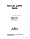
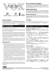
Figure 3-1.
Front and Rear Panel Controls, Indicators, and Connectors
01779 -2
HP 419A DC Null Voltmeter.max
Model 4 1 9A
Section III
SECTION III
OPERATING
INSTRUCTIONS
c . Depress ZERO pushbutton. If meter does not
indicate zero, perform the m eter zero adjust
ments (Paragraphs 5 - 3 1 thru 5-3 6) .
3-1. I NTRODU CTIO N.
3 -2 . The Model 4 1 9A functions as a dc voltmeter with
full (end) scale ranges from 3 flV to 1000 V. An in
ternal bucking supply allows e ssentially infinite input
im pedance to b e achieved on the 3 fl V to 300 m V ranges.
The Model 4 1 9A can also mea sure low level dc cur
rents with full (end) scale ranges from 30 pA to 30 nA .
This section de scribes the operating procedures and
presents some applications for the Model 419A.
d.
3 -8 .
TURN-ON PROC EDURE (AC LINE OPERATION).
a.
3-3. CO NTROLS, I NDICATORS AND CO N NECTORS.
3 -4. Each operating control , indicator and connector
located on the Model 4 19A is identified in Figure 3- 1 .
The description o f ea ch component i s keyed t o the il
lustration of that com ponent which is included within
the figure .
3 -6. The Model 4 19A may be operated on its internal
battery power supply or from a n ac line . The instru
ment operates on its internal batteries wheneve r the
ac power cable is removed from the ac power con
nector. Line operation occurs automatically whenever
the power cable is connected to the power conne ctor.
b.
Connect ac power conne cto r to the line using
the ac power cable supplied .
c.
Set RANGE switch to 1 V.
d.
Depre ss ZERO pushbutton. If meter doe s not
indicate zero, perform meter zero adjustments
(Paragraphs 5- 3 1 thru 5-36) .
e.
Zero m eter on 3 IJV range with ZERO control.
Periodically recheck setting of zero control on
the 3 flV range .
----- NOTE -----3 -9 .
DC VOLTAGE MEASUREMENTS .
a.
NOTE
------
Disco nnect the power cable from
the power receptacle for battery
operation.
a.
Depress BAT. TEST pushbutton; if meter does
not indicate within BAT lim its, perform battery
charging proc edure (Paragra ph 3 - 1 3) .
-----
NOTE
-----
Whe n the 419A is re ce ived or
after a period of storage (es
pecially at high tem perature s ) ,
the batteries may require changing.
E rratic and inaccurate operation
may re sult if the instrument is
operated on weak batterie s .
b.
Set RANGE switch to 1 V.
Turn on the Model 4 19A andzero it according
to the steps in Paragraph 3 7 (battery operation)
or Paragraph 3 -8 (AC Line Operation). Allow
at least ten minute s warmup time if low voltages
(below 1 mY) are to be measured.
-
3 - 7 . TURN -ON PROCEDURE (BATTERY OPE RATION).
----
Set line voltage two -position slide switch (rear
panel) to corre ct position for available line
voltage .
DAMAGE TO INSTRUMENT MA Y
RESULT IF LINE VOLTAGE
SWITCH IS SET INCORRE CTLY .
3-5. OPERATING I NSTRU CTIO NS.
Best isolation characteristics and
freedom from ground loop prob 1em s results when the 41 9A is
operated on its internal battery
supply.
Zero meter o n 3 flV range with ZERO control.
Periodically recheck setting of ZERO control
on the 3 flV range .
b.
Connect te st leads to + and INPUT term inals.
(See Table 1-3 f or a list of test leads availah le. )
c.
Set RANGE switch to range neare st ahove input
voltage . If in doubt, start on the 1000 V range
and downrange as necessary.
-
TO PREVENT DAMAGE TO THE
MODEL 419A, DO NOT EXCEED
THE FOLLOWING OVE RLOAD
LIMITS .
RANGE
3 IJV to 3 mV
10 mV to 300 mV
1 V to 1000 V
M AXIMUM INPUT VOLTAGE
50 Vdc
500 Vdc
1200 Vdc
3-1
01 779 -2
HP 419A DC Null Voltmeter.max
Model 419A
Section III
d.
Connect test leads to voltage to be measured.
f��'�;',
��1
-A -: ;
��
� -:
-
3 -14. The batteries are automatically trickle charged
whenever the Model 419A is connected to an ac power
-
A
A A A
line and the ZERO, VM/ AM, SET NULL or READ NULL
pushbutton is depressed. The instrument may be used
while trickle charging occurs except when the batteries
DO NOT FLOAT MODEL 419A -IN
PUT TERMINAL MORE THAN ± 500
VDC FROM GROUND (
e.
3 -13. Battery Charging Procedure.
-4:- ).
Depress VM/ AM pushbutton.
Read value of
input voltage on meter scale.
l-Jlt'
If input voltage is 300 mV or less,
infinite input impedance maybe ob
tained by proceeding with steps
f
g.
Rotate NULL control until meter
Ua..LLC;� �t:;�
...... J.."""
lrl
i:)J.1UU.l.U
h.n. n4- In.,,,",c.-i- "'f"\�+;...,,11""T
ut:; c:L .... .l.t:;a.o .... pc\'.l. ... ..u::\...1..1.J
..... _nJ,"
..... "..
n.rl
5°C;U
.1. t:;\...-UU.L
3 -15. The batteries may be fast charged by connecting
thru h.
Depress SET NULL pushbutton.
.... h_ hoi-l-_"".;',...."r..
before using the instrument. Generally, 72 hours of
trickle charging will restore the batteries to their
fully charged state; however, the batteries may be
trickle charged indefinitely without damage.
----- NOTE ------
f.
have been almost completely discharged. Under this
condition the Model 419A may not operate properly and
the Model 419A to an ac powerline and depressing the
FAST CHG. pus hbutton. The instrument cannot be used
to make measurements while fast charging the batteries.
The batteries should reach full charge in approximately
indicates
15 hours.
exactly zero.
-----
3 -16. To obtain maximum battery life, the following
points should be observed.
NOTE-----
NULL control gives both coarse
and fine adjustment. Rotate con
trol until pointer is slightly down
scale from zero; then reverse
direction to obtain fL'1e adjustment.
h.
Depress READ NULL pushbutton.
of input voltage on meter.
Turn on andzero the Model 419A according to
the steps in Paragraph 3 -7 (Battery Operation)
or 3-8 (AC Line Operation). Allow at least ten
minutes warmup time if low value currents
(below 10 nA) are to be measured.
+
Do not allow the batteries to discharge below
the BAT limits on the meter scale.
b.
Use fast charge only when necessary.
c.
Charge the batteries in moderate tern peratures
(80 0F ± 10 0F, 270C ± 5. 60C) whenever possible.
d.
Do not store the instrument at temperatures
above 1220F (500C) or below -400F (-200C).
Read value
3 -10. DC CURRENT MEASUREMENTS.
a.
a.
b.
Connect test leads to
c.
Set RANGE to range nearest above current to be
measured. If in doubt, start on 300 nA position
and - INPUT terminals.
and reduce as necessary.
d.
Connect test leads in series with current to be
measured.
e.
Depress VM/AM pushbutton. Read value of in
put current on meter scale.
3-17. APPLICATIONS.
3-18. In addition to straightforward dc voltage and
current measurements, the Model 419A has a number
of applications. Several of these are presented in the
following paragraphs.
3 -19. Measuring Leakage.
3 -20. By using the Model 419A as a sensitive dc am
meter, very high resistance leakage paths in insulating
materials can be detected and measured. Leakage is
observed by connecting the output of a dc power supply
across the insulating material and placing the Model
419A in series with one of the power supply leads. By
noting the current flow on the Model 419 A, the leakage
resistance can be calculated from the formula:
R
3 -11. Amplifier Output.
3 -12. The rear panel OUTPUT terminals provide a dc
voltage which is proportional to meter deflection.
The
LEVE L control adjusts the maximum value of output
voltage.
With the LEVEL control turned fully cw,
the
voltag-e varies from 0 to ± 1 Vdc into a 1 kQ load.
Polarity of the voltage depends upon polarity of the
meter deflection.
-
E
(power supply)
(leakage) -
I
(419A)
Example:
Assume the leakage between
2 points
B)
in a standards laboratory oil bath
be
measured.
(A and
is
to
A 100 V power supply and the
419A are connected as
shown in Figure 3-2.
01779 -2
3 -2
HP 419A DC Null Voltmeter.max
Section III
M odel 4 1 9A
3 -2 1 . Calib rating A Voltage Source .
hp
3 -2 2. The Model 4 19A can serve as a very sensitive
and ac curate null detector. These feature s can be
espec ially useful when matching the output of an ad
justab le voltage source to a reference standard. The
adjustab le voltage source and the reference standard
are connected in serie s opposition with the Model 4 1 9A
in serie s with one of the leads. The adjustab le voltage
source is then adjusted for a null indication on the
Model 419A .
419A
(BATTERY OPERATIO N)
POWER
SUPPLY
IOOV
Example:
t
Assum e the output of a dc standard ( -hp- Model
7 4 1B ) is to b e matched to the output of a 1 V trans
fer standard ( -hp - Model 73 5A) . These instru
ment s and the M odel 41 9A are connected as shown
in F igure 3 - 3 .
B
OIL BATH
F igure 3 -2 .
Leakage Measurement
A s sume the 419 A indicates 10 pA . The leakage of
the oil can then be calculated .
=
R
E
(leakage)
R
(leakage)
R
(leakage)
=
=
R
(leakage )
=
The reference standard and the adjustab le voltage
source are b oth s et for a 1 V output. The Mode l
419A indicates any deviations b etween the two out
puts . By making internal adjustm ents affecting the
output of the voltage source until null is reached
on the Model 41 9A's 3 /lV range, the output of the
adjustab le voltage source is very accurately
matched to the reference standard.
3 ....2 3 . �Y1easurLl'}g and Re cordi....'1g Drift .
(power supply)
1
(419A)
3 -2 4 . The rear panel OUTPUT terminals provide a dc
voltage (0 to ± 1 V) proportional to m eter deflection.
This output can be used to record the drift of a dc
voltage sour ce when that source is compared to a very
stable reference voltage.
100 V
10 pA
Exam ple :
10 1 3 Q
Assume that the drift of a 10 V power supply is to be
ob served and recorded. The power supply, Model
4 19A, stable voltage source ( -hp- M odel 740B ) and
a strip chart reco rder (-hp - Sanborn Model 7701A )
a r e connected a s shown i n Figure 3 -4 .
10 7 MQ
A DJUSTABLE VOLTAGE SOURCE
��l:Ft
NULL
REFERENC E S T ANDARD
DC
S
+T1.
11
.:�I
I
-z-l��
' .f-
I.OOOOOOV
OUTPUT
419A - B -0994
@
DETECTOR
hD
419A
AC-DC lNMI
DC STANDARD
hp 741B
I [�[ [ [1
I�Qi' �I I� 1
@
I
I
I
_________-"
F igure 3 - 3 .
Calibrating A D C Standard
0 1 779 -2
3-3
HP 419A DC Null Voltmeter.max
Model 419A
Section III
STRIP CHART RECORDER
n
DRIFT
'O
I
DETECTOR
hp 419A
POWER SUPPLY
IOV
l
hp 770lA
(SANBORNJ
°
I
TO OUTPUT
TERMINALS
��___--->J ON REAR PANEL
0
D@
@@
, gDD
n
":i�J
TO REAR
PANEL INPUT
STABL E VOLTAGE
S OURCE
DC STANDARD/LlVM
hp 7408
l[�lo
10V OUTPUT
?
4!9A-8-0992
Figure 3 -4.
Measuring Power Supply Drift
The output of the stable voltage source or the power:
supply is adjusted until the Model 419A indicates null.
The voltage range used on the Model 419A depends
variation (on the 10 mV range) and supply the strip
chart recorder with a voltage that changes from
on how much drift is anticipated from the power
supply. If the power supply output drifts 8 mV over
drift is amplified by a factor of 100.
Gains as
high as 333, 000 (on the 3 /lV range) are available
when the Model 419A is used on the lower ranges.
a period of time, the Model 419A will indicate this
o to 0. 8 V over the same period.
In this case,
the
01779-2
3 -4
HP 419A DC Null Voltmeter.max
w
(1)
(")
�
I
o
�
o·
::l
<
BT5
AND
PlOSI
BUCKING
SU PPLY
HP 419A DC Null Voltmeter.max
r+
INPUT
I
I
�
�
419A-RO
"1
I
r +�
_
r - -,
I
PlOSI
INPUT
ATTENUATOR
�
PlO A3
MODULATOR
�
L
R3
�
f
PlO
A4 AC
AMPLIFIER
--< L
-=
.J
O A3
DEMODULATOR
OSI
FEEDBACK
CONTR OL
�SIIRI?.
�
o
0..
o
�
...J
...J
(,0
t\:)
�
rOUTPUT
___ _
L
_J
------... L
V
I -IN PUT I
)
SIR26
R2:
�
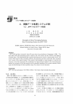
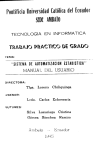
Figure 4-1.
Model 419A Block Db,
�
�
(,0
�
Model 4 19 A
Section
IV
SECTION IV
THEORY OF
4- 1.
I NTRODU CTIO N.
4 -2 . This section contains the theory of operation of
the Model 4 19A DC Null Volbneter .
4- 3.
GE NERAL DES CRIPTIO N.
4 - 4 . The Model 4 1 9A functions as a dc voltmeter, a
dc null voltm eter and a dc amm ete r . When used as a
dc voltmete r , the Model 4 19A provides end scale ranges
from 3 11 V to 1000 V with an input resistance of 100
kQ to 100 MQ, depending on the range selected. When
used as a dc null voltmeter, end scale ranges from
311 V to 300 m V are provided with infinite input re
sistance . End scale ranges from 3G,pA t o 3 0 n A are
provided in the ammeter function with a c onstant
100 kQ input resistance .
4 - 5 . When used as an ammeter, circuit operation i�
identical to the voltmeter mode of operation . Current
values are derived from the voltage drop across the
constant 100 kQ input resistance on the 30 pA- (3 IlV)
to 30 nA (3 mY) range s .
4 - 6 . A dc voltage being measured with the Model 4 19 A
i s applied to the Input Attenuator through the + and INPUT term inals, located on the front panel. In the dc
voltmeter and ammeter modes, the input is applied to
the input attenuator through SlR2 6. In the dc null volt
meter mode, the output of the Bucking Supply is applied
to SlR2 6 in ser ies opposition to the input dc voltage .
The diffe rence b etween the Bucking Supply output and
the input dc voltage is applied to the Input Attenuator .
Table 4 -1 lists the attenuation factors provided by the
Input Attenuator for all ranges.
OPERATION
4 - 7 . The dc output of the Input Attenuator is modulated
by the M odulator . The Modulator is com prised of two
photocells which are alternately illwninated by two
neon lam ps . The output of the modulator is a square
wave whose amplitude is proportional to the difference
between the amplitudes of the input dc voltage and the
feedback.
4 -8. The square wave output of the modulator is amp
lified by the AC Am plifier. The AC Amplifier is a
six - stage, high gain amplifier . Its output is applied
to the Demodulator . The Demodulator output is a dc
level whose amplitude is proportional to the amplitude
of the square wa ve . The Demodulator output is applied
to the DC Amplifier, a three - stage voltage and power
amplifie r .
4 - 9 . The forward gain provided by the AC and DC
Amplifiers for each range is listed in Table 4 - 1 . The
output of the DC Amplifier (approximately 1 Vdc for
end s cale meter deflection) is applied to M 1 and is also
available at the OUTPUT + and - terminals .
4 - 10 . The Feedback C ontrol circuit i s ganged to the
T...... """ ......
�1.'pU""
A ........ n'n.,... ......... I""I._ h·U' .... hn D A l\T��
........ 'C'.I.1uQ.. .... V.l. UJ ....l,n:; �\.oC1J.''-A.L:.I
.£"'1
..'I7'; .... ,...h C!1
C"
OVV.l. .... ""l.l
U.L.
I"J'1hn .f.o.n.A
.1..J.I.'C;
.I...:;;-.;:;u ....
b ack provided by the F eedback C ontrol circuit is li sted
in Table 4 - 1 . Algebraic addition of attenuation factor,
forward gain and feedback gives the closed loop gain .
The closed loop gain provides 18 end scale ranges in
10 dB steps .
4-11.
DETAILED DES CRIPTIO N.
4 - 12 . BUCKING SUPPLY (See F igure 6 - 3 ) .
4 - 1 3 . Dc input voltages up to 2 00 m V m ay b e measured
in either the dc voltmeter mode or the null voltmeter
Tab le 4 - 1 . M odel 419A Attenuation and Gain Characte ristic s
RANGE
3 IlV/ 30 pA
10 IlV/ 100 pA
30 IlV / 3 00 pA
100 IlV /1000 pA
3 00 11 V /3000 pA
1mV/lOnA
3 m V/ 30 nA
10 mV
30 mV
100 mV
300 mV
1 V
3 V
10 V
30 V
100 V
3 00 V
1000 V
ATTENUATION FACTOR
dB .)
dB ,'I
dB ,«
dB ,''1
dB j lI..
dB
OdB
- 2 0 dB
- 20 dB
- 40 dB
- 40 dB
- 60 dB
- 60 dB
- 80 dB
- 80 dB
- 1 00 dB
- 100 dB \�I
- 1 2 0 dB
o
o
o
o
o
o
FORWARD GAIN
+ 1 50
+ 1 50
+ 1 50
+ 1 50
+130
+130
+120
+120
+120
+120
+120
+120
+120
+120
+12 0
+120
+120
+120
dB
dB
dB
dB
dB
dB
dB
dB
dB
dB
dB
dB
dB
dB
dB
dB
dB
dB
FEEDBACK
- 40
- 50
- 60
-70
-60
-70
-70
- 60
-70
- 60
-70
- 60
-70
- 60
-70
- 60
-70
-60
dB
dB
dB
dB
dB
dB
dB
dB
dB
dB
dB
dB
dB
dB
dB
dB
dB
dB
CLOSED LOOP GAIN
+110 dB
+100 dB
.
nn An
�V LlD
+
+
+
+
+
+
+
+
80 dB
70 dB
60 dB
50 dB
40 dB
3 0 dB
2 0 dB
10 dB
OdB
10 dB
2 0 dB
3 0 dB
40 dB
50 dB
60 dB
T
-
4-1
0 1 779 -2
HP 419A DC Null Voltmeter.max
Model 41 9A
Section IV
m ode. In the dc voltmeter mode , the input voltage is
applied to the Input Attenuator through the + and INPUT terminals and through S 1 R26. In the null volt
meter m ode , the input is applied in the same manne r ,
but i s opposedby the bucking vultage applied t o S1R26 .
4 - 14 . When the SET NULL Pushbutton i s depress ed,
the BT5 voltage is applied through R4 and R 5 and the
voltage divider network (S 1Rl thru S1Rll) to S1R26.
The difference b etween the input voltage and the bucking
voltage is indicated on the Meter M 1. The bucking
voltage is then adjusted through the use of course and
fine NULL controls (R4 and R5) until a null is indicated
on the Mete r . When the READ NULL Pushbutton is
depre ssed, the input voltage is disconnected and the
polarity of the bucking voltage is reversed. The value
of the bucking voltage (equal to input voltage) is indi
cated on the Meter M 1 .
4 - 1 5 . INPUT ATTENUATOR.
4 - 16 . All voltages and currents to be measured are
applied to the input attenuator, which is a resistive
divider consisting of S 1R20 to S1R2 5 and R3 . The
attenuation factor depends upon the pos ition of the
RANGE switch. The attenuator is divided into two
separate networks to provide the proper impedance
levels for filter capacitors A3C2 and A3C3 . (Tab le 4 - 1
lists the attenuation factors for all range s . )
A 1 r, TPt.TT\TT"'" T7'1TT rnDn
':1:-.1.1 • .LJ.'Iru.l. £.I..l..J.I..c.n.
4 - 18. L1 and L2 , and A3C2 and A3C3 filter superim
posed ac noise from the input signal .
4 - 19 . MODULA TOR/DEMODULATOR.
4 -20 . The m odulator/demodulator is a photo - conductive
chopper. It consists of a neon oscillator with two neon
bulbs and four photocells mounted in one as semb ly .
The photocells have an extremely high res istance when
not illuminated, and a very low resistance when il
luminated.
4 -2 1 . Assume that A3Vl is illuminated and A3V2 is
not . The resistance of A3V2 will be many times greate r
than the re sistance of A3V 1 . The voltage across A3V2
(input voltage) w ill be applied through A 3C4 to the base
of Q1. The oscillator will then switch off the bulb il
lum inating A3V 1 , and switch on a bulb w hich illuminates
A3V2 . A3Vl now has the greatest resistance, and
A3V2 is a virtual short to the feedback which is coupled
to Q1. The m odulator provides a square wave output
ryrr.YV"\.,.ti
0:> 1 +r. +ho rHffo.,.on,..o hohl1oon +ho rl,.. ;n\'"'\11 + .,nrl
V.I..I.'-'4. ... "'"'...., "'...... ....., '-4...1..&. .............. .1. ....... "-' """",,,,yy ...... .....,.1.1 "............... v .L... J..tJu. ... ""... ... \A
.1-'''' V!-'V.&. ...... rm
of Q1 provides b ias stab ilization . Ac feedback from
the em itter of Q3 to the emitter of Q1 is used to vary
the gain of Q1 thru Q3 . Thi s is accom plished by varying
the amount of feedback to Q1 , due to the position of
the RANGE Switch . In the 3 /1V to 1 mV range, re
sistor R7 is shorted out, de creasing the negative feed
back applied to Q 1 .
4-2 5 . F eedback from the emiiters of Q6 and Q7 is also
controlled to vary the gain of Q4 thru Q7 . In the 3 /1V
to 100 /1 V range resistor R16 is shorted out, de creasing
the negative feedback applied to Q4 . Capacitors A3C4
and A4C9 couple the ac input and output and b lock the
dc bias voltage s .
4 -26. D C AMPLIFIE R .
4 -2 7 . The output of the dem odulator i s applied t o a
four stage voltage and pow er amplifier. Q9 provides
temperature compensation for the cir cuit. When Q8
and Q9 increase conduction due to a rise in tempera
ture , the emitter to base voltage of Q4 decreases,
which decreases the Q8 forward bias. This maintains
Q8 conduction at a constant level .
4 -28 . The final stage of am plification is a corn pli
mentary symmetry am plifier consisting of Q12 , Q13,
CR13 and CRl4. The diodes bias the transisto rs at a
constant idling state, with no input signal applied.
When an input is applied, the transistor responds im
mediately with an output . The input doe s not have to
reach a certain amplitude to cause conduction in the
transisto rs, since they are already at an idling con
dition .
4 -29. The output of the dc amplifier will be 1 V for
end scale input on all range s . An output i s al so ap
plied to the + and - OUTPUT term ina ls J 5 and J6 .
Adjustable resistor R2 provides control of the rec order
output from 0 to ± 1 volt end scale . Diode network
CR 5 to CR12 protects the amplifier circuit from an
overload .
4 -3 0 . M E TE R CIRCUIT.
4 -31. The m eter is a current driven device which
utilizes a taut band movement . A 1 volt output of the
dc amplifier provides end scale needle deflection on
all ranges . During F AST CHARGE and off (positions
1 and 2 of Function Switch S2 ), the meter is protected
from transient voltages by a short across it . During
the BATTERY TEST mode (position 3 of Function
Switch S2 ), resistor S2Rl provides the amplifier load;
b ecause the meter is disconnected from the amplifier
c ircuit .
A_�,)
�-V"'.
'D.oC";cofn,... C'" nA1 +n OAA "'''''''''''IT;,lr\ ,f,,_ rlI"\1;1.""\_.-"4-';'""....,,
,L\.. ...... O.l.Q\.. V.l...::J .L\.""'X'&' LV .I.\'''''""x
'X
lJ.L V V.Lu.c; LU!. \,...Q..l.
. J.j.J,L Cll.J..Vl1
f
.......
VI.
dc feedback signals . The square wave frequency w ill
depend upon the switching frequency of the neon oscil
lator .
the mete r . The re sisto rs are connected in parallel
with the m eter as a Ifunction of the RANGE switch
setting.
4 -22 . The dem odulator is operated by the neon oscil
lator in the sam e manne r . It provides a dc output
proportional io the amplitude of the square wave input .
4 - 33 . F EEDBACK CONTROL .
4 -2 3 . AC AMP LIFIER.
4 -2 4 . Amplification of the square wave output from the
m odulator is provided by a six stage direct -coupled
amplif ier . Dc feedback from the base of Q4 to the base
4 -3 4 . Control of feedback is accomplished through a
deck of the RANGE switch . The amount of feedback
depends upon the position of the RANGE switch. The
clo sed loop gain of the amplifier may be determined
by subtracting the feedback from the forward .9'ain.
The feedback pruvided for each range is listed in
Table 4 -1.
01 779-2
4-2
HP 419A DC Null Voltmeter.max
M odel 4 19 A
Section
4 -3 5 . POWER SUPPLY AND NEON DRIVE R
(Figure 6 -4) .
4 -3 6 . The power source for the 4 19A is four recharge
able batterie s , which supply a +13 V and a -13 V output .
The 41 9A may also b e operated from line voltage,
which will trickle -charge the batteries during operation .
4 -3 7 . The line input may b e either 1 1 5 V or 230 V from
50 to 1000 Hz. The input is rectified by CR1 thru CR4
and applied to series regulator Q1 .
4 -38. Zener diode CR5 supplies a constant ref erence
to the base of Q 1 . The emitter o f Q1 is referenced to
the voltage across R2 or R3 . If. the output current in
crease s , Q1 will conduct le s s , due to le ss em itter to
base b ias . This w ill decrease the output current . If
either output decrease s , Q1 will conduct harder , in
c reasing the output current .
4 -3 9 . The neon driver consists of a series re gulator
circuit , a blocking oscillator, and a neon circuit .
Transistor Q5 and zener diode C R9 provide a c onstant
refe rence to serie s regulator Q4 . The frequency of
the blocking oscillator is controlled by varying the
voltage across C 3 . This is acc omplished through ad
justable re sistor R9, which controls the b ias on the
b ase of Q4 .
4 -4 0 . Due to inherent characteristic s , either Q2 or
Q3 will conduct harder when power is applied . A ssume
that Q2 conducts m ore than Q3 . As Q2 conducts, a
negative going signal is coupled through T2 to the base
IV
of Q3 . This causes Q3 to cut off com pletely. At the
same time, a positive going signal is coupled to the
base of Q2 , causing it to conduct more . While Q2 is
conducting, a negative output will be coupled to the
neon circuit .
4-4 1 . When T2 b ecom e s saturated, the positive signal
is rem oved from the base of Q2 , and it cuts off . At
the same tim e , the negative signal is removed from
the base of Q3 , allow ing it to start croducting. As Q3
conduct s , a negative going signal is applied to the base
of Q2 , holding it cut off, and a po sitive going signal
is applied to the base of Q3 . Q3 continue s to conduct ,
causing a positive output to be coupled to the neon cir
cuit . This will continue until T2 becom e s saturated,
and starts the cycle over again .
4 -42 . The output of the oscillator is c oupled through
T2 to the neon circuit. When an input is applied to
the c ircuit , due to inherent resistance characteristics,
either DS1 or DS2 w ill light , depending upon which has
the least re sistance .
4 -43 . Assume that DS 1 lights when the input is applied
to T2 . Capacitor C 1 charges until the oscillator
switches the input, and DS 1 goes off . When the os
cillator switches again, the charge on C 1 insures that
DS2 fires, and DS1 stays off . This cycle continues
with DS1 and the DS2 firing , as long as there is an
output f rom the oscillator . C RI and C R2 prevent the
capacitor from discharging through R1 and R2 .
4 -3
0 1779 -2
HP 419A DC Null Voltmeter.max
Section V
Model 4 19A
Table 5 - 1 . Test Equipment Required
INSTRUMENT TYPE
REQUIRED CHARACTERISTICS
Voltmeter Calibrator
DC Voltage Range : 0 . 3 mV to 300 V
Accuracy: ± 0 . 2 %
-hp - Model 738BR Voltm eter
Calibrator
Strip Chart Reco rder
Voltage Range : 1 Vdc
Speed: 50 mm/sec
F requency Response: 5Hz
Sanborn Model 7701A
Strip C hart Recorde r
Oscillator
Output F req: 60 Hz
Output Voltage : 0 . 5 V rms
-hp- Model 2 08A Oscillator
Oscilloscope
Horizontal Sensitivity: 2 ms/cm
Vertical Sensitivity: 50 mV/cm
Frequency Respon se: 100 kHz
-hp- Model 130C Oscilloscope
Electronic C ounter
C ounting Range: 300 to 400 pps
Accuracy : ± 1 count
-hp- Model 52 1 1A Electronic
C ounter
DC Voltmeter
Voltage Range : 30 Vdc
Accuracy: ± 2 %
-hp- Model 427A Voltm eter
Capacitor
0 . 1 /IF ± 2 0 % 10 Vac
-hp- Part No . 0 1 7 0 -0085
�
- . -�
100 n ± O" 1% 1/8 W ww
Re sistors
600 n ± 1% 1/8 W comp
;
-hp- Part No. 081 1 -0398
-hp - Part No . 0684 - 103 1,� .
�'.
10 kn ± O . 2 5% 1/8 W met flm
-hp- Part No . 069 8-3193
100 kn ± O. 2 5% 1/8 W m et flm
-hp- Part No . 0698-4057
900 kn ± 0 . 5% 1/2 W m et flm
-hp - Part No . 0 698- 5488
1 Mn ± O. 1 % 1/8 W ww
-hp- Part No . 0698- 5443
hp 419A
DC NUll
VOLTMETER
VOLTMETER CALIBRATOR
hp738BR
�
10 n
n
o
-
-hp- Part No . 081 1-0473
'"
9 Mn ± O . 5% 1/2 W met flm
1°
REC OMMENDED MODEL
III�II@III
I RI! ,� "�, 1
0
=
�------��
B
���----�
R2
IMEGn
A
RI
loon
� --419A- 8 - 0290A
F igure 5 - 1 . Voltmeter A c curacy Performance Test Setup
0 1 7 7 9 -2
5-0
HP 419A DC Null Voltmeter.max
Section V
Model 4 19 A
SECTION V
MAINTENANCE
5-7 .
5-1. I NTRODU CTION.
5 -8 . The voltmeter accuracy performance te st setup
is illustrated in Figure 5- 1. A voltmeter calibrator
( -hp- Model 738BR), a 100 n re sistor (-hp- Part No.
08 1 1 -0398) , and a 1Mflre sistor (-hp- Part No . 081 1 0473) are required for this test .
5 -2 . This section contains the information nece s sary
for maintenance of the Mode l 4 19A DC Null Voltmete r .
Included a r e perf ormanc e tests, repair procedure s ,
adjustment and calibration procedure s , and trouble
shooting procedure s .
5-3. TEST EQUIPME NT.
5 -4. The test equipment required for maintenance of
the Model 4 19A is listed in Tab le 5 - 1 . Equipment
having sim ila r characteristics may be substituted for
the equipment listed .
5 -9 .
5-5. PERFORMAN CE TESTS.
STE P
VOLTME TE R
CALIBRATOR
DC OUTPUT
a.
C onnect test setup illustrated in Figure 5 - 1 .
b.
Make control settings indicated in step 1 of
Table 5 -2 ; if Model 419A reading is not within
tolerances listed, perform Full Scale Cali
b ration procedure (Paragraph 5 -3 7 ) .
c.
Repeat step b for remaining steps in Tab le 5 -2 .
BUCKING VOLTAGE TEST.
5 - 1 0 . No external te st equipment is required for the
bucking voltage performance test.
5 -6. The performance tests presented in this section
are front-panel proc edure s designed to compare the
Model 41 9A with its published specifications (Table 1 - 1) .
These tests m ay b e incorporated in periodic main
tenance, post repair, and Lncoming quality control in
spection . The se tests should be conduct�d b efore any
attempt is made at instrument calibration.
Table 5 -2 .
VOLTMETER ACCURAC Y TE ST.
a.
Depress 4 19A READ NULL pushbutton;
RANGE to 300 m V .
b.
Rotate NULL contro l fully clockwise and then
fully counterclockw ise; if 4 1 9 A meter does
not peg in negative and positive direction,
respectively, replace BT 5.
Accuracy Performance Test, Supplemental Data
POINT OF
MEASUREMENT
FIGURE 5-1
4 19A
RANGE
41 9A
:READING
1
30
mV
A
3 /lV
2 . 84 to
3 . 16
2
100
mV
A
1 0 /lV
9 . 7 to
10. 3
3
300
mV
A
3 0 /lV
29.3 to
30. 7
V
A
100 /lV
9 7 . 9 to 102 . 1
�
300 /lV
2 9 3 . 9 to 306. 1
4
1. 0
5
0. 3 mV
6
1
mV
7
3
mV
8
10
mV
9
30
mV
set
B
B
10
100
mV
11
300
mV
B
12
1
V
B
13
3
V
B
14
10
V
15
30
V
16
100
17
18
B
�
0 . 98 to
3 mV
2 . 94 to 3 . 06
10 m V
30 mV
Remove
Atten uator
1 . 02
1 mV
100 mV
300 mV
9 . 8 to
10. 2
29 . 4 to 3 0 . 6
98 to
102
2 9 4 to
306
1
V
0.98 to
1. 02
3
V
2.94 to
3 . 06
B
10
V
9 . 8 to
10. 2
B
30
V
V
B
100
V
98 to
102
300
V
B
300
V
2 9 4 to
3 06
300
V
B
1000
V
2 80 to
320
29 . 4 to 3 0 . 6
5 -1
01779 -2
HP 419A DC Null Voltmeter.max
Model 419A
Section V
hp 419A
DC NULL
VOLTMETER
VOL TMETER CALIBRA TO R
hp 738BR
y
0
0
�
0
0
��@
0
ll�llgl
0
oQ®
,
���
�
0
0
0
I I I I I 11
900Kil
9Mil
�
Figure 5-2.
Ammeter Accuracy Test Setup
5-11. AMMETER ACCURACY TEST.
d.
5-12. The ammeter accuracy performance test is il
corder does not show OUTPUT at 95% between
lustrated in Figure 5-2. A voltmeter calibrator (-hp
Model 738BR), a 9 Mf2 resistor (-hp- Part No. 06985443) and a 900 kst resistor (-hp- Part No. 0698-5488)
are required for this test.
a.
2 and 3 seconds, perform Chopper Adjustment
(Paragraph 5-33).
e.
Connect test setup illustrated in Figure 5 -2.
b.
Set Model 419Aand voltmeter calibrator con
trols as indicated in step 1 of Table 5-3.
f.
CALIBRATOR
DC OUTPUT
1
419A
30 pA
.3 mV
419A
2
.00 1
V
100 pA
96 to
104
3
.003
V
300 pA
290 to
3 10
4
.0 1
V
1000 pA
970 to 1030
5
.03
V
3000 pA
2910 to 3090
6
.1
V
10 nA
9.7 to 10.3
7
.3
V
30 nA
29.1 to 30.9
graph 5-33).
a 10 kSlresistor (-hp- Part No. 0684-1031), and
+
a.
b.
c.
for
a.
Connect strip chart recorder to 419A
b.
Construct test setup illustrated in Figure 5-1;
turn voltmeter
and -
calibrator dc output off and
setfor 30 mV output; connect 419A + INPUT
terminal to Point A.
c.
0. 1
for this test .
resistor (-hp- Part No. 081 1-0398), and a 1 Mst re
required
a
MF capacitor (-hp- Part No. 0 170-0085) are required
Set 419A RANGE switch to 3 MV position; de
press VM/ AM pushbutton.
Connect test setup illustrated in Figure 5-3;
do not connect oscillator.
Depress 419A SET NULL pushbutton; set NULL
control for +9 11 V on 10 IIV range.
Connect oscillator and set its output frequency
for 60 Hz; output voltage for O. 5 volts rms.
Model 419A reading should not vary more than
5-14. A strip chart recorder (Sanborn Model 7701A),
a voltmeter calibrator (-hp- Model 738BR), a 100 st
OUTPUT terminals.
(Para
5-16. The superimposed ac rejection test setup is il
5- 13. RESPONSE TIME TEST.
this test.
re
lustrated in Figure 5-3.
An oscillator (-hp- Model
208A), a 600 st resistor (-hp- Part No. 0727 -0081),
28. 1 to 31. 9
sistor (-hp- Part No. 081 1-0473) are
if ship chart
5-15. SUPERIMPOSED AC REJECTION TEST.
READING
RANGE
Start strip chart recorder and turn voltmeter
calibrator dc output on;
1 second, perform Chopper Adjustment
tolerances, troubleshoot the input attenuator
(Paragraph 5-49).
VOLTMETER
set for 100 mV output; set 419A RANGE switch
corder does not show OUTPUT at 95':n within
Model 419A reading is not within the listed
STEP
Turn voltmeter calibrator dc output off and
to 10 MV position.
If
Table 5-3. Ammeter Accuracy Test
Start strip chart recorder and turn voltmeter
calibrator dc output on; if strip chart re
±
0.2 /lV after the initial transient.
5-17. NOISE TEST.
5-18. No external test equipment is required for the
noise test.
+
a.
Short 419A
b.
Zero 419A in VM function on 3 IIV RANGE.
c.
If noise displayed on 419A meter exceeds 0.3
and - INPUT terminals.
pV p-p, perform Chopper Adjustment (Para
graph 5-33).
0 1779-2
5-2
HP 419A DC Null Voltmeter.max
Model 4 19A
Section V
hp 419A
DC NULL
VOLTM ET ER
TES T OSCILLA TOR
hp 208A
I � II ©
@g
'@
I)
���
-@-
l
��I
I I� I I� I
r&
0
v�
-:::k
::R2
600n
-0291
Cl
O . l fL F
.,
"
':::f<::
F igure 5 - 3 .
RI
1 0 Kn
>iC
Superimposed A C Rejection Performance Test Setup
5 - 1 9 . INPUT RE SISTANCE TE ST.
5 - 2 0 . A Voltmeter Ca lib rator ( -hp- Model 7 3 8BR) , a
10 k S1 re sistor ( -hp- Part No. 0698-3193 ) , a 100 kS1
resistor ( -hp- Part No. 069 8 - 40 57 ) , a 1 MQ resistor
( -hp- Part No. 07 57 - 1 0 54) and a 10 M S1 re sistor ( -hp
Part No . 0698 -4 128) are required for this te st .
a.
Connect a 1 0 kS1 re sistor t o Model 4 1 9 A
PUT terminal .
b.
C onnect voltmeter calibrator dc output ter
m inals to 10 k S1 resistor and -INPUT terminal
on the Model 41 9A.
+
i.
Set Model 41 9A RANGE t o 1 0 0 m Y ; set volt
m eter calibrator output to 100 m V ( . 1 V ) .
j.
Model 4 19A should read 90. 9 mV which veri
fies an input resistance of 10 MS1 on the 100
mV range .
k.
Replace the 1 MS1 re sistor with a 10 MS1 re
sistor.
1.
Set Model 4 1 9A RANGE to 1 V; set voltmeter
calibrator output to 1 V .
IN
c.
Set Model 4 19A RANGE to 3 m V; set voltmeter
calib rator output to 3 mV ( . 003 V) .
d.
The Mode l 41 9A should indicate 2. 73 mV which
verifies an input re sistance of 100 kQ on the
3 rhV range , as given by the following formula:
m. Model 4 19A should read 0 . 909 V which veri
fie s an input re sistance of 100 MS1 on the 1 V
range .
5 - 2 1. REPAIR PRO CEDURES.
R.
ill
R xE
s
m
E - E
m
o
where Rin is the 4 1 9A input re sistance, R s
is the series resistance , E m is the voltage
indicated on the Model 41 9A meter and E o is
the voltmeter calibrator output voltage.
------ NOTE
------
The input resistance may vary slightly
and a t � lerance of ± 3% should be allowed.
e.
Replace the 10 k S1 resistor with a 100 k S1 re
sistor.
f.
Set Model 419A RANGE t o 1 0 mY; s e t volt
m eter calibrator output to 10 m V ( . 0 1 V ) .
g . M odel 4 19A should read 9. 09 mV which veri
fies an input re sistance of 1 MS1 on the 10 m V
range .
h.
Replace the 1 0 0 k Q re sistor with a 1 MS1 re
sistor .
5 - 2 2 . COVER REMOVAL.
5 -2 3 . When it is necessary to repair or adjust the
Model 419A, one or more covers w ill have to be re
moved. Refer to the following steps for cover removal
procedure .
a.
TOP COVER. Remove top cover screws; slide
cover to rear and lift to remove .
b.
SIDE COVERS. Remove four screws from
side cover; lift to remove.
c . BOTTOM COVER. Remove bottom c over
screw s at rear of cover. Slide cover to rear
and remove .
5 -2 4 . SERVICING PRINTED CIRC UIT BOARDS.
5 -2 5. The M odel 419A has two etched circuit b oards .
Use caution when removing to avoid damaging m ounted
components. The assembly and -hp - part number
are etched on the interior of the circuit board to
identify them . Refer to Section VII for parts replace
ment and -hp - part number information .
5 -2 6 . The etched circuit boards are a plated-through
type . The electrical connection b etween side s of the
board is made by a layer of metal plated through the
com ponent hole s . When w orking on these boards ,
observe the following general rules .
5-3
0 1 779 -2
HP 419A DC Null Voltmeter.max
M odel 419A
Section V
a . To avoid contamination, wear clean lint -free
cotton or rubbe r glove s .
b.
c.
Use a low -heat (2 5 t o 50 watts) small -tip sol
dering iron and a small diameter rosin c ore
solder .
C ircuit compone nts can b e removed b y placing
the solde ring iron on the component lead on
either s ide of the b oard and pulling up on lead.
If a com ponent is obviously damaged, clip leads
as close to c om ponent as pos sible and then
remove . Excess heat can cause the circuit
and b oard to separate or cause damage to the
com ponent.
d.
Component lead hole should b e cleaned bef ore
inserting new lead .
e.
To replace component s , shape new leads and
insert them in holes . Reheat with iron and
add solder as required to insure a good ele c
trical c onnection .
f.
C lean excess flux from the connection and ad
joining area.
g. To avoid surface contam ination of the printed
circuit, clean with weak s o lution of warm water
and m ild detergent after repai r . Rinse thor
oughly w ith clean water . When completely
dry , spray lightly w ith Krylon (#1302 or equi
valent) .
dures should be conducted only if it has been previously
established by Performance Tests (Paragraphs 5 - 5
to 5 -2 0) that the M odel 4 1 9A i s out of adjustment.
5 -3 1 . MECHANICAL ZERO ADJUSTMENT .
5 -32 . The m echanical z e ro adjustment is located on
the instrum ent front panel . If the meter pointer does
not indicate zero whe n the instrument power ha s been
off for at least one minute , mechanically zero the
meter follow ing the proc edure outlined below .
a.
Turn instrument power off; disconnec1 input
signal; remove output cable; and allow one
m inute for m eter pointer to stabiliz e .
b.
Rotate ze ro adjustment CW until pointer is to
left of zero, m oving upscale . Continue until
pointer is at zero. If pointer overshoots zero,
repeat operation.
c . When the pointer is exactly at zero, rotate
z ero adjustment slightly C CW to free it . If
the meter pointer moves to the left during this
step, repeat steps b and c.
5-33 . C HOPPE R ADJUSTMENT.
5 -3 4 . An Oscillosc ope ( -hp- Model 130C ) and an Elec
tronic C ounter ( -hp- Model 52 1 1A) are required for the
chopper adjustme nt.
�Lr------
5 - 2 7 . INSTALLATION OF RE PLA CEMENT NEON
SUBASSEMBLY ( -hp- Part No . 1990 -02 14) .
5 -28. Physical alignment and neon selection are c ri
tical. When trouble is isolated to the neon subas semb ly ,
the com plete subassembly should be changed rather
than replacing the defective neons.
a.
Remove the top and side cover on the m eter
side of the instrum ent .
b . Disconnect the neon subas sembly lea-ds from
pins on A2 b oard. (Note location for re con
necting the new leads) . Maneuve:r subassembly
cable through the grommet on the inner shie ld.
c.
Remove the tw o photochopper as sembly m ount
in g screw s and remove neon subassemb ly .
d.
Install new neon subas sembly. Note that the
rubber grommet on the subassembly is offset
toward the top of the instrume nt .
e.
Route the neon subassembly cable through the
inner shield and reconnect the cable to the
A2 b oard.
f.
Replace the side c over and recalibrate the
Model 4 19A as outlined in Paragraph 5 - 2 9 .
5-29. A DJUSTM E NT A N D CALI B R ATIO N.
5 -3 0 . The following is a com plete adjustment and cali
b ration procedure for the Model 4 19A . These proce -
NOTE -------
Serial Prefix of instrument is 5 1 4 - ,
refe r t o Appe ndix C fo r choppe r ad
justment information.
If
a.
Remove 4 19A top cover and shield .
b . C onnect Oscillo s cope and Electronic Counter
to A2TP2 .
c.
Set Oscillosc ope for 2 m s/
cm horiz ontal sen
sitivity and 50 m V /
cm ve rtical sensitivity.
d.
Adjust A2R9 (FREQ . ) for Electro nic C ounter
indication of 320 to 340. (This c orre sponds
to chopper rate of 160 - 1 70 pps as Electronic
Counter also counts smalle r pulse s . ) Adjust
A2R5 (NEON CURRENT) for waveform am p
litude of 140 to 160 m V. F igure 5-4 show s
the chopper waveform .
-----
NOTE
-------
the �Teon \X/a\'eform is unstable , an
intermittent neon bulb is indicated.
See Paragraph 5-27 for replacem ent
information.
If
e.
If correct waveform i s obtained and re sponse
time is still not w ithin lim its of Paragraph 5- 13,
A4R26will have to be resele cted . If response
on 3 /J.V range is longer than 3 seconds , the
value of A4R2 6 should be decreased. If re
sponse on 3 /J.V range is less than 2 seconds ,
5-4
01 779 -2
HP 419A DC Null Voltmeter.max
Model 4 19A
Section V
A4R2 6 should be inc reased. A4R2 6 should be
between 6 . 8 k51 and 15 k51 with a typical value
of 10 k 51. A4 F2 6 is an Allen -B radley, com
position, 1/4 watt ± 10%, resistor .
I 1 1 1 1 1 11 1 1 1 I
f.
Set Voltmeter Calibrator for 1 V output; con
nect 419A to Point B ; adjust A4R44 ( 1 V) for
full scale deflection on 1 \T range .
5 - 3 9 . BATTERY TEST CALIBRATION.
5-40 . A DC Voltmeter ( -hp - Model 427A) is required
for the battery test calib ration .
------ NOTE ------
I
T
l
..,
I
v
419A-R0
.....,
I
',......
Figure 5 - 4 .
"-
l.
....
..�
a.
b.
..
...a
..&
r--
,-
.......,
l
...
...
Neon Drive Waveform (A2TP2)
5 - 3 5 . E L ECTRICAL ZERO ADJUSTMENT .
5 - 3 6 . The electrical zero adjustment should be �L'
form ed when the mete r pointer does not indicate zero
on the 1 volt range when instrument power has been on
for at least one minute . No external equipment is re
quired for this adjustment.
a . Set 419A controls a s follows:
RANGE
1 V
ZERO pushbutton . . . . . . . Depre ssed
.
•
•
•
.
•
•
.
.
•
•
.
.
Batteries must be fully charged b e
fore performing this procedure . (See
Paragraph 3 - 13 ) .
.
•
.
Remove 4 19A top cover and shield.
Connect DC Voltmeter across B T 1 thru BT4.
DC Voltmeter indicate s le ss than 26 V, re
charge " battery power supply in accordance
with Paragraph 3 - 1 3 . If DC Voltmeter indi
cates at least 26 V , proceed to step c .
If
c . Depres s Model 419A BAT TEST Pushbutton;
adjust A4 R2 5 (BAT TEST CJ;A�L) for Ivlode1 4191\.
Meter reading (0 -3 scale) equal to DC Volt
meter reading in step b .
1 \ f\
/'1.: '..
5-41 . TROU'B"L ES HOOTlNG.
>
5-42 . This section contains information designed to
assist in the isolation of malfunctions . These checks
should be undertaken only after it has been established
that the trouble cannot be elim inated by the Adjustment
and Calibration Procedures , Paragraph 5-2 9 .
----- NOTE------
b . Remove top cover; adjust A4R14 ( 1 V Z ERO
for zero deflection on 419A meter .
The 419A operates erratically when
the charge on the batte rie s is mar
ginal. Since the exact capacity of the
Nickel Cadmium batteries cannot be
determined by voltage measurements,
it is advisable to charge the batteries
b efore troubleshooting.
5 - 3 7 . FULL SCA LE CALIBRATION.
5 -38 . The full scale calib ration consists of performing
the 3 fl V, 10 {.lV , 1 mY, and 1 V adjustments . A Volt
m eter Calib rator ( -hp - Model 738BR) , a 100 51 Resistor
( -hp- Part No . 08 1 1 -0398) and a 1 MSl Resistor ( -hp
Part No . 08 1 1 -0473) are required for this test.
a . COllJl€Ct test setup illustrated in Figllre 5 � 1 .
5 -43 . NO RESPONSE TO INPUT .
b.
5-44. If the meter does not re spond to input (usually
accompanied by a constant offset near full scale after
meter has been on for one or two minute s ) , proceed
as follows:
Remove 4 19A top cover; depres s VM/AMpush
button.
c . Set Voltmeter Calibrator for 30 mV output;
connect 4 19A to Point A; adjust A4R41 (3 flV)
for fu�l scale deflection on 3 flV range .
d.
Set Voltmeter Calib rator for 100 mV output;
connect 4 1 9A to Point A; adjust A4R42 (10 flV)
for full scale deflection on 10 flV range .
a.
----- NOTE -----Remove re sistive attenuator b efore
performing steps e and f .
e.
Set Voltm eter Calibrator for 1 m V output;
connect 419A to Point B ; adjust A4R43 ( 1 MV)
for full scale deflection on 1 m V range .
b.
c.
If one neon is bad, all the pulses at A2TP2
will be the same amplitude . If the blocking
oscillator is bad, there will be no pul ses at
A2TP2 .
Check for approxL.'T1ately 8 volts de at the
emitter of Q4 to isolate between the blocking
oscillator and its voltage regulator .
If the neon waveform at A2TP2 is correct, the
trouble is in the am plifier .
5-5
0 1779 -2
HP 419A DC Null Voltmeter.max
Model 4 19A
Section V
5 - 4 5 . POSITIVE OR NEGATIVE FOLDOVE R.
5-46. Foldover i s when the meter needle pegs and then
returns on scale when the input is overloaded.
positive foldover o ccur s , check A4Q12 f or
low gain.
a.
If
b.
If
negative foldover occurs , check for low
gaLll in A4Q13 and for a leaky A4C8 or C 12 .
5 - 5 1 . RE PLACEMENT OF FACTORY SELECTED
C OMPONENTS .
5- 52 . Certain com ponents within the M od el 4 1 9A a re
individually selected in order to com pensate for slightly
varying circuit parame te r s . These com ponents are
identified by an asterisk ( *) on the schematic diagrams
and a typical value is shown. The following paragraphs
desc ribe the function of the factory selected com ponents
and give replacement instructions .
,
5 -47 . EXC ESSIVE NOISE .
5 - 53 . A4R26*.
5-48. If the 419 A meter noise is in exc ess of 0. 3 /l V
peak -to -peak, proceed a s follow s :
5 - 54. A4R2 6 * is factory selected to provide prope r
amplifie r response time . Response tim e can be evalu
ated by performing the Re sponse Time Test (Para
graph 5 - 13 ) . A4R26 * should be replaced only if re
sponse time cannot be corrected by perform ing the
chopper adjustment procedure (Paragraphs 5-33 ) .
Paragraph 5-34 step e gives s pecific replacement in
struction s .
a.
Che ck the batte rie s for low charge .
b.
Check the chopper frequency in accordance
with Paragraph 5-33 . M isadjustment of chop
pe r frequency or drive or a m i sfiring neon
bulb w ill cause noise .
c.
C lean the pin conne ctors on the A 4 board w ith
a fiberglass b rush or typewriter eraser and
ensure they are makL'1g good c onnections ..
d.
Check the transisto r s in the A C Amplifier for
noise (A4Q1 or Q2 m ost probable ) .
5 -49 . TROUBLESHOOTING THE INPUT ATTENUATOR.
5 - 50 . If trouble is suspected in the input attenuator or
feedback divide r , proceed as follow s :
a.
Rotate the range switch through all positions
several tim es to clean the switch contacts .
5- 5 5 . A4R47 *.
5-56 . A4R47 * is factory selected to provide approxi
mately 1 . 1 Vdc at the rear panel OUTPUT term inals
into a 1 k S1 load with the LE VEL control turned fully
cw and a full scale input applied to the INPUT ter
m inal s . Once A4R47 * ha s been selected at the factory,
there should be no reason to change its value unle ss
one of the output transistors A4Q12 and A4Q13 or one
of the diodes A4CR13 and A4CR14 is replaced. Factory
values of A4R4 7 * range from 16 kS1 to 20 kS1 with a
typical value of 18 kS1 . A4R4 7 * is an Allen-Bradley
2 watt re sistor. If the value of
com position ± 5% 1/
A4R47 * must be changed, proceed as follow s :
a.
Apply a 1 Vdc input to the Model 4 1 9A , INPUT
term inals (1 V range) .
b.
Check the 9 0 M S1 resisto r (S l R3 ) for dust ac
cumulation; clean if ne cessary .
b.
c.
If trouble pe rsist s , carefully check the input
attenuator and feedback divider resistors .
Connect a 1 kS1 load across the rear panel
OUTPUT terminal s .
c.
Turn LEVEL control fully cw .
d.
Measure the voltage across the load . If the
voltage is le s s than 1 . 0 Vdc , in crease the value
of A4R4 7 *; if the voltage is greater than 1 . 1 5
Vdc, reduce the value of A4R47 *.
e.
After replac ing A4R47 * , perform the Full
Scale Calibration procedure (Paragraph 5-3 7 ) .
----
NOTE
------
Parallel paths exist for several
of the resistor s . Befo re re
placing a suspected re sistor, un
solder one lead and check the re
sistor again.
0 1 779-2
5-6
HP 419A DC Null Voltmeter.max
Section VI
Model 4 19A
SECTION VI
CIRCUIT DIAGRAMS
a r e provided for the metering c ircuit and the power
supply cir cuit.
6 - 1. I NTRODU CTIO N.
6- 2. This section c ontains the circuit diagrams nec
es sary for the operation and m�intenance of the Model
4 19A DC Null Voltmeter . Inc luded ar e schematic and
c omponent location diagram s .
6 - 5 . COMP O NE N T LO CA TIO N DIAGRAMS.
6 - 3 . S C HEMATI C DIAGRAMS.
6-6. The physical c onfiguration of the 4 19A is shown
on the component location diagrams. Each c omponent
is identified by reference designation.
6-4 . The electr ical configuration of the 4 19A is shown
on the schematic diagram s. Individual schematics
REFE RE N CE
DESI G NAT I O NS
P A R T I A L R E F E R E N C E D E S I G N A. T I O N S
ASSEMBLY
COMPLETE
OR
S U B AS S E M B LY
A R E
SHOWN:
DESIGNATION(S)
PREFIX WITH
O R
BOTH
FOR
DES IGNAT ION.
C O MPLETE
DESIGNAT I O N
ASSEMBLY
S U B A S S E M B LY
COMPONENT
A2
NONE
Q1
A 2 Q1
A2
A1
R1
A2A1 R1
NONE
N O N E
J1
J1
ASJembly
Reference
Designation
ASJembly
Name
ASJembly Part Number
( includes A 2 A 1 subaSJembly)
�';-P PLY ASSE.;;L� I03460 - 6';;; ;;-'
�
,-A-, ,r-------A--�\ �
. .
.�
I
---< 21
Number mdJCales p m
Plug and lack
-----..
A2 1
111
QI
---=( 3,
/} /
��
I1 \
\
Wire Cola,.: Calor code same as resistor
calor code. First number indicates base
cola,., second number indentifies wider strip,
thi,.d number indicates narrower strip.
denotes WHY·RED·YEL wire.
E.g. �
POWER
I
AI
/
Subassembly of A2
�
T
�I R I
T
�I
IPH OTO-CHOPPER
\
,I
Eyelet or standoff terminal
may or may not be numbered
OSCillATOR I
11�
0 1 7 79 -2
J
1,;;-
:1
I
y
l
6 J2
>
I
I
i��
II
not mounted on
ASJembly A 2
D,,_i� of wi"
Assembly A 3, Pin 4
/v
A3 (4)
Pin may or may not
be numbered
�) �
I I�
�
I
!.Male . standoff
pin connector
Female pin connector
on a WHY.RED wire
.
STD-A - I DOO
6- 1
HP 419A DC Null Voltmeter.max
Section VI
Model 419A
,n
"�
'>c'
I
A3R3
A3C3
A3C�"
A3CR3
..
"
'"
•
®
"
"
"
--......
"
Figure 6-1. Model U9A. Component Loc�tion Diagram
SI TOP VIEW
SI BOTTOM VIEW
Figure 6-2. Range Switch Sl. Component Location Diagram
01779-1
'-2
HP 419A DC Null Voltmeter.max
1.
PARTIAL REFERENCE
FOR
WITH ASSEMBLY OR S
2.
COMPLETE DES!I
E
COMPONE�T VALU S
WISE NOTED.
�
3.
CAPACITANCE
C
H,
RESISTANCE IN
DENOTES POWER
W
W DENOTE,)
DENOTES POWER :
:8
@
S
o
ID
'"
'"
J
�
<t
o
o
- CRI6-
-CRI5-
@
-CRI3-
- CI I -
-R20-
-RI6 -
- R40 -
- R3 0 -
--QJI]-
- R51-
-R21-
-RI8-
- R 26*-
- R36 -
- R3 5 -
- R37-
- R24- R2 2 -R 23 -
�
- R3 3 -
-0-OlD-0- -{
J--1
J-
----�-'
CI2
C9
- R49 -
-QJD-
Part No.
- R47*-
- R39-
t
A4
004 1 9 66504 )
�
I RA N G E !
FUNCT I O N
'\
SWITCH
CDS
®
SIRI
680K
S I R2
220K
68K
SIR3
S I R4
22K
®
(J)
SIRI I
1 0K
®
S I R?
1 20 K
S I R8
39K
@
SIR9
1 2K
®
S I RIO
3 300
@O
IsErl
�
®
t\
lOcI
�
®
Isiiil
�
@
V I EW
IsETl
�
®
IoCl
�
®
EJ
<D
���[EJcii!][:�::J
IsATl
�
®
C1IJ
CQJ
! FAST!
CHG
®
HP 419A DC Null Voltmeter.max
6.
�
•
DEJOTES FR(
::: = ::: ::: J DENOTES REl
DENOTES SCE
0
®s
(j)
e
®
@
®
®0
@o
@0
@0
�
l'rV e ®
BT5
�
®
@o
.�
®
0
®
®0
�
�
@
®
@0
CD,
®
0
@
@o
R A N G E S W I TC H
�CD
@
0
®0
@o
1A( R )
@
©0
SI
c:::Q:J
NULL
fFAsil
�
®
®
©o
®o
BOTTOM
I READ!
IJ)
S I R5
1 . 2M
SJR6
390K
®
rREAol
�
(J)
c::=J
IRANGEI
R)
S ' D_(�
�
2� CD
O_S0
P�_
�I��
I/�CD
���
�2
>J
� * r,
rr====================== S 2 ======================4
5.
SI R26
IK
@
f
•
- R3 8 -
C8
(hp
SIGNAL I
___ _ _ _
- R48 -
- R I7 -
,---_
"-------.....
4 ISA- 6- 099S
S
- R3 J -
- CR9 -
- R I9-
- R 50 -
4.
-CRIO-
- C R I4 -
5
�"
2200
NULL
( 3 0 0 MV MAX d
�'4 "
�
COA RSE
\
L
1
5K
�_
1 5 0C
_ _ _ _ __ _ _ _
220C
1.
------- N OT E S ------,.
PARTIAL REFERENCE DESIGNATIONS ARE SHOWN. PREFIX
WITH ASSEMBLY OR SImASSEMRLY DESIGNATION (S) OR BOTH
FOR
2.
COMPLETE
�
DESIGNA TION.
COLOR CODE SAME AS RESISTOR
FTRBT NUMBER TDENTIF'mS BASE ("01.0R
COLOR CODE
DENOTES WIRE COLOR:
SECOND NUMBER IDENTIFIES WIDER STRIP. THIRD
(e. g.
�
oWIllTE . RED
I
RESISTANCE IN OHMS
3.
4.
�
W
W
(CHASSIS )
GROUND.
DENOTES POWER SUPPLY COMMON.
DENOTES SIGNAL COMMON.
___ _ _ ___ DENOTES ASSEMBLY.
8.
*
6.
9.
10.
::: = ==J DENOTES REAR PANEL MARKING.
�
<D P/0 S2
�- -' t::
@
@
®
(j)
®
®
@
®
<DSIA(R )
""r:
6 S 0K
i���
S
���
S I R4
22K
S I R I I SIR5
1
10K .2M
S I R6
390K
S I R?
1 20K
S I RS
39K
S I R9
1 2K
SIRIO
3 300
@0
®
�
I
®
0
®0
0
· @O
@
0
@
@0
@
®
;.--{)s-,o�(�o-:r","�
�
@
@
@
SIR25
9.06M
®
�o
@0
@0
@0
@0
GRN
YEL
BLU
8
VIO
GY
9
WHT
5·51
FOR REPLACEMENT
DENOTES TWISTED PAIR.
;10(0.
1
V RANGE . INPUT SHORT ED.
� t;c� . '
MO;�A-:;:;;-l
I
'"
I
.
VI
I
0
I
C2 ..l
1 .0
CR'
DS2
,{/
CR4
C4
CHOP PER ASSEMBLY
PlO A 3 PHOTO
6300 1 )
( 0 0 4 1--''--- 9-- '----- - -
I
I
[
);!1 r
V2
..l C3
.47
R3
100
'
�
R6
2200
COARSE
INUlL!
��
L-_-,-+< R4
5K
\
L
R5
1500
@
@
0
--1
\
______ _ ___ _
R3
90M
0
FINE
®
0
@
@0
(j)
(j)
®
-0
(i5)
::J: �:
®
®0
RED
VOLT AGES INDICATED IN RED ARE MEASURED WITH VM
SIR27
S E )
S E (F
....=. '��
�;,,;;;;'
I =D==...�=:�
�_-c==,
) ,
SI R24
906K
®0
8=
PUSH BUTTON DEPRESSED
(j)
®0
SEE PARAGRAPH
ALL VOLTAGES ARE
®
@0
®0
<D P/O S2
�<D
7
@
BRN
ORN
DENOTES SCREWDRIVER ADJUST.
I RANGE I
<D S I O (R)
BLK
INSTRUCTIONS.
DENOTES AC FEEDBACK PATH.
S I R26
IK
If
FACTORY.
c:::::::J DENOTES FRONT PANEL MARKING.
5.
0
1
2
3
4
5
6
7
I
AVERAGE VALUE SHOWN. OPTIMUM VALUE SELECTED AT
--�------ DENOTES DC FEEDBACK PATH.
-�.
_-____-_
.-
YELLOW.
WIRE COLOR
CAPACITANCE IN MICROFARADS
DENOTES POWER LINE
------- DENOTES MAIN SIGNAL PATH.
I RANGE I
)
NUMBER IDENTIFIES NARROWER STRIP.
COMPONENT VALUES ARE SHOWN AS FOLWWS UNLESS OTHER
WISE NOTED.
@
ti'iI
0 -.:..:::/
ti'iI
�� "R"rf!
@
@
0
®0
S IR23
90K
S I R22
9K
@
@ . 900
@
®
®
0
@
0
@
S I R20
1 00
SI
2
RANGE S W I TCH
S2
EJI
FF
<D
FAST
CHG.
®
F UNCTION SWITCH
�.ll
IrBAT
@
ZER O
@
1sErl 1
1 1vMl
��
®
®
READ
NULL
(j)
I
4 1 9A - J - Q963
HP 419A DC Null Voltmeter.max
CO
F
- N OT E S ---7. � DENOTES WIRE COLOR:
COLOR CODE.
COLOR CODE SAME AS RESISTOR
(e. g.
�
THIRD
FIRST NUMBER IDENTIFIES BASE COLOR.
SECOND NUMBER IDENTIFIES WIDER STRIP.
�WHlTE. RED, YELLOW. )
I
I
WIRE COLOR
n
2
3
4
5
6
1
BLK
BRN
SI B(Rl0
I
v
@
ORN
YEL
:®
9.
10
1t
WHT
VALUE SHOWN
o®
o®
INS TRUCTIONS.
DENOTES TWISTED PAIR.
o@
VOLT AGES lNDlCATED IN RED ARE MEASURED WITH VM
;10'1,.
PUSHBUTTON DEPRESSED, 1 V RANGE ,
A L L VOLTAGES ARE
o@
o®
INPUT SHORT ED.
- - --- - - ---
AMPLIFIER ASSE MBLY (004 19- 66504)
R3
1 20K
Cl +
l Ot
C6
10
RI6 +
lOOK
o@
o@
DS2
:
I
o®
o@
MO�U�A-:;;;-l
I
I
RI
475K
@
R2
1 78K
���--r���:I�' �----�&�'8��1'2�
RANGE \
0SIE(F) SIR27
15K
@
@
�
®
SIR24
906K
®
SIR25
9.06M
@
� LI
I
I
I
-0 -0
SIR23
90K
SI R��
®
@
S�R��
1 00
CR4
R3
1 00
PHOTO CHOPPER ASSEMBLY
(0041 9-63001)
_ _ ___ _ _
// ,
V2
I
I
�
0
0@
�
u
I RANGE I
0SIB(F)
SIB(R)0
®
@
@
�
®
(])
®0
®0
t::
�
@0
-S-
16
@0
®0
2
®
0
0@
@0
R8
475K
®
0
@0
@0
@
(])
0
0®
+/2V
+
RIB
10K
RI9
IK
C7
� IO
R20
-/2V
R9
4.7M
RIO
4700
RII
2.2M
-.L
(;3
T ·OOI
C5 ..L
.001
T
IV ZERO
L+
I ���
@
0
0@
@
0
RI3
CR2
CRI
56K
- 12V --�Y---�--�--�
@
0
0
@
R22
1 20K
lOOK
R5
56
C2
200
®
@
RI7
120K
I w
�
0
- --- - - -
�
@
����
2 �--�--��--- �------�
+
R7
R6
@
5600
1 20
Iii\
0=
@0
@
2,.
®
Iii\
�o
®0
®
r
SIR2 1
C3
.47
'---_--'1..-._
.
®
�6M
CR3
C2
1 .0
PlO A 3
VI
C4
L2 b j �
;I'/" 1
-
I
I
/j)
OPTIMUM VALUE SELECTED AT
S E E PARAGRAPH 5 - 5 1 FOR REPLACEMENT
.
- ---
3 �(------.
I
,,�
GRN
DLU
VIO
FACTORY.
�
3 I.
�
RED
GY
8 . * AVERAGE
.----r-- METER
A4
I RANGE I
NUMBER IDENTIFIES NARROWER STRIP.
L- - - --- - - --
_ _ _ ___
_ _ __
10
SIRI9
3M
4 1 9 A - J - 0963
COP I R I G H T 1966 B Y HEW LET T - PACKARD COMPANY
HP 419A DC Null Voltmeter.max
:TER
AMPLIFIER
A S S E M B LY
(00 4 1 9 - 66 5 0 4 )
+ 1 3V
+/2V
R3
120K
RI7
120K
C6
10
RI6
l O OK
+
+/2V
�
+
RI8
10K
+
+
C7
IO
R49
2200
CS
1 00
+1 2V
RI9
IK
CR9
CR6
CRIO
CR7
CRI I
R27
IM
R 20
lOOK
R2
178K
CR5
R40
100
R23
IK
R22
1 20K
R28
2 2K
�
Q' ��I : '
- O� 5 V
R21
22K
)
+
R33
220K
R35
220C
R29
CR I 5
R6
5600
R34
220(
+/I.6V
lPI
C2
200
R32
220K
-/IV
R5
56
R31
220K
R30
47 0K
R24
IK
R7
1 20
-/2V
-/2V
,
"
R36
2200
- 1 3V
- 1 2V
F
le
R9
4.7M
R8
475K
RIO
4700
RII
2.2M
. C5
OO '
T
IV
�6�
Z E RO
I
�
��------��
RI3
- ' ''�'
--- -
I�'
� l:
--1�6� -'
JIO
-�
C
�
- --- - - --- - - __
__��__________________________�
SIRI9
3M
C
RI2
'
� + < 2V
R25
IK
"
9
'V
I
l[W t[W T1 l:
+13V
-.v
- - --- - - --- - - --- - - ----
-.v
--
F
'-V
--
'-V
--
M
52(20
i Z E RO I
HP 419A DC Null Voltmeter.max
F
52(23)
- --- - -
--
Model 4 19A
Section
VI
--- - - --- - - --- - - --- - - --- - - --- - - --- - - ---...,
I
I
I
+ 1 3V
+12V
R49
2200
CR9
CRIO
CRI I
R50
1 0K
R40
100
R27
IM
�
��4 l-CR4
R3I
220K
�
I
R46
390K
�
-
-O.5V
R33
220K
QI3
-12.5V
14
CI5
221+
CI7 +
22
+
+
CIO
1' 4.7
17
R47*
18K
R48
68K
3 1lV
�
1 0 llV
�
I MV
�
+1 3V
S2(2il
S2(23)
rri i
----t --% -:-r]: -
Q) P/O S 2
@
@
R51
2200
MI
V
PlO S 2 Q)
26
@
@
@
@
®
®
@
CI6
39
31
+
r.::L"
I - I
L.. "= .J
16
-/3V S 2 (2 1 )
@
(7)
R35
2200
- 1 3V
- 1 3V
J7
�
16
QI2
J6
..----��----..--..--����..��--� 1 9 r_-----2�O���
(7)
R36
2200
-12V
�
18
R34
2200
j �
CRI4
��
R 4'5
50CiK
R32
220K
DV
BAT. TEST
CAL
J5
[���LJ
I
IV
�
R4 1
250K
R42
250K
14
�
20
I
I
I
R 3
250K
I RA.NG E I
Q) SIC (F)(R)
I
@
@
@
®
(7)
�>--V\1v----72 2 >--+-----'0
-=
4
I
®
L :, �
2:J
--- - - --- - - --- - - --- - -
@
©
:
@
®
@)
Figure 6-3 . Amplifier and Amplifier Switching
Schematic and Component Location
Diagram s
0 1 779 -2
HP 419A DC Null Voltmeter.max
6 -3/6-4
CURRENT RED WHT BLK WHT
SLK FREQ
\
C2
I - -�
I
L:J-J '�R7'--'-'� L:s-J �2.
-' 2 - - '3 R 0
�
�
-4
-CR2- Cl
TI
- CR3��R4_
·,,·-,-�,m t ,\
�R6-
I
-
-
n�
WHT
WHT GRY WHT
GRY SRN SRN RED VIO
GRN
GRY YEL
GRY
(hp
1.
�\"h/-, �
- �-
T2
8
f 1"
-- N O T E S -( )
PARTIAL REFERENCE DESIGNATIONS ARE SHOWN.
PREFIX
WITH ASSEMBLY OR SUBASSEMBLY DESIGNATION S
OR BOTH
COMPONENT VALUES ARE SHOWN AS FOLLOWS UNLESS OTHER
WISE NOTED.
RESISTANCE IN OHMS
CAPACITANCE IN MICROFARADS
3.
4.
�
W
DENOTES POWER LINE
(CHASSIS )
GROUND.
DENOTES POWER SUPPLY COMMON.
---- DENOTES ASSEMBLY.
- - - - - - - DENOTES SUBASSEMBLY.
�W&� DENOTES COMPONENTS NOT MOUNTED
5.
6.
.. �
ON
ASSEMBLY.
C===J DENOTES REAR PANEL MARKING.
�
DENOTES SC REWDRIVER ADJUST.
7. � DENOTES WffiE
COLOR CODE.
COLOR:
COLOR CODE SAME AS RESISTOR
FffiST NUMBER IDENTIFIES BASE COLOR,
SECOND NUMBER IDENTIFIES WIDER STRIP, THIRD
(e. g. �
)
NUMBER IDENTIFIES NARROWER STRIP.
� WHITE, RED, YELLOW.
WffiE COLOR
0
1
2
4
5
6
7
3
8.
B LK
BRN
RED
ORN
YEL
GRN
B LU
VIO
8
GY
9
WHT
SEE PARAGRAPH 5 -2 7 .
INDIVIDUAL COMPONENTS ON A3Al ARE NOT SEPARATELY
REPLACEABLE.
HP 419A DC Null Voltmeter.max
0
SLK WHT
BLK
BLK
RED
VIO
004 1 9-6650 2 )
FOR COMPLETE DESIGNATION.
2.
@
�WHT
A2
Part No.
C3
- RI I -RI2 - CR7- CRB -CR 9-
Model
419)
A N D NEON DRIVER A S S E M B LY (004 1 9 - 6(5 5 0 2 )
fFusEl
WI
]' r)------J;,-
lY.§ _�
caB
POWER S U P PLY
T!
JI
�----���---
�J �5--------��
���
�______
�____
____
R2
750
52
F U N C T I O N S W I TC H
Io;;l
\
�
<D
FA ST
CHG.
]f8AT.l1
�
A3
OO
®
......
Pi a
@
Z ERO
@
1��
1vMl�\
®
CH O P P ER
PH T
...1 ( 0 0 4 1 9 - 6 3 0 0 1 )
__
®
" SE"BLY
I
I
\ 990-0214
:
\:
I
I
)
\
\
L
(])
I
I
NEON DR I V E R
rl -2-.-----l---,O>tl-:-, -: -----i!�i--'
R l
R
,N EON S U BA S SEMB
LY - AI
R EAD
NULL
Le
8)
( SE E N OTE
Cl
----
�
_
I
=
::::.
2
L, : I
�
_ _
\
I
I
I
I
DSI
gj
_J
e
_
--,
I
l--1�!!--�I----�
!l
ii
1
I
1
I
1
I
1
I
I
1
I
1
1
I
I
1
!!
I
1
1 I
::
!
I
I
!
1
I
I
I
I
I
\
I
J
.01
lI :I
: I'
I
I
I
I
1
I
- !3
V
I
R7
51
R8
51
I
I
1
1
- 1 3V --
1
l..... _ _ _ _ _ _ .....J
TP2
4J9.4 - D - 0974
COPYR I GHT
1966 BY H E W L E TT - PACKAR D COMPANY
---
--
---
0 1779 - 2
HP 419A DC Null Voltmeter.max
-
Model 4 1 9A
Section VI
- -
3 S E M B LY ( 00 4 1 9 -6,5 5 0 2 )
P OWE R ' S U P P LY
l
I
I
RI
150
7
+
R4
33K
Cl
65
I
5
�77m/mJ//T�
�
P/O S2 <D
>-------z;r-o
;';:
I�
�
�(
o® 22
��
�
a®
I
®
I
C2
.01
,I
I
I
�
J
fI�
��
�
(J)
I
I
QI
I
;/$&$////:%1
I
I
I
NEO N D RI VE R
Q4
11
Q2
30
<D
®
()--+()
0
TI
A: :
)
� v
1
a
a®
a
+
"I
6
�
a@
L
R3
560
O S2
I I.
I
R2
750
P/
I
)
BT 4
®
23
TO
A4(17)
@
®
®
(J)
P�<D
®
32
0
®
�
�
®
21
11
-/�lL.
TO
A 4 ( 1 5)
(J)
+1 V
CR7
R IO
4 700
CR8
J
�J
C4
- 1 3V
05
I
I
RI!
IM
_ 1 3V
���____________�------�
____
9
I
I
V------------------�
I3L
-u
----�)�--�
I
F igure 6 -4. Power Supply and Neon Driver,
Schematic and C om ponent Location
Diagrams
0 1779 -2
6-5
HP 419A DC Null Voltmeter.max
Section VII
M odel 4 19A
SECT I ON
VII
REP LACEA BL E
7 -1.
7 -3. Miscellaneous parts a r e listed a t the end of
Tab le 7 - 1 .
INTRODU CTION.
7 -2 . This section contains information for o rder ing
replacement parts . Table 7 - 1 lists parts in alpha
m eric orde r of their reference des ignators and indi
cates the description, -hp - part number of each part ,
together w ith any applicable note s , and provides the
following :
a.
b . De scription of the part.
tions b elow . )
d.
ORDERING INFORMATION .
7-4.
7 - 5 . To obtain replacement parts , address orde r or
inquiry t o your local Hewlett-Packard F ield Office .
(See Appendix B for list of office locations . ) Identify
parts by their Hewlett - Packard part number s . Include
instrument model and serial numb ers .
Total quantity used in the instrument (TQ
column) . The total quantity of a part is given
the f irst time the part number appears .
c.
PART S
7 -6 .
NON-LISTED PARTS.
7 -7.
T o obtain a part that is n ot listed, include:
(See list of abb revia
a. Instrument model numb e r .
Typical m anufacturer of the part in a f ive
digit code . (See Appendix A for list of manu
facturer s . )
b.
Manufacturer ' s part numb e r .
d.
Instrument se rial numb e r .
c . Description o f the part .
Function and location of the part .
DESIGNATORS
A
B'
C
CR
DL
DS
E
= assembly
motor
= battery
= capacitor
=
=
=
-�
�
diode
delay line
lamp
misc electronic part
F
FL
HR
J
K
L
M
MC
=
MP
fuse
P
filter
= heater
= jack
= relay
= inductor
=
Q
QCR
R
RT
= meter
= microcircuit
S
T
= mechanical part
=
=
A
Au
C
cer
coef
corn
comp
conn
= silver
= aluminum
= ampere (s)
= gold
=
=
capacitor
ceramic
coefficient
= common
= composition
=
=
connection
DPST
= deposited
= double-pole doublethro\v
= double-pole single-
elect
= electrolytic
dep
DPDT
encap
F
FET
fxd
GaAs
GHz
throw
=
encapsulated
= farad (s)
= field effect transistor
= fixed
gallium arsenide
= gigahertz = 10+9 hertz
=
= guard (ed)
gd
Ge
grd
= germanium
= ground (ed)
H
Hg
Hz
= henry (ies)
= mercury
= hertz (cycle (s) per
ID
impg
incd
ins
= inside diameter
= impregnated
= incandescent
= insulation (ed)
kQ
= kilohm (s)
=
10+3 ohms
kHz
= kilohertz = 10+3 hertz
L
Un
= inductor
= linear taper
log
m
mA
MHz
= logarithmic taper
=
=
MQ
met fIm =
=
mfr
=
mtg
mV
fJ.
/.LV
my
nA
NC
Ne
NO
NPO
second)
®
milli = 1 0 -3
= milliampere (s) = 10-3
amperes
+6 hertz
= megahertz = 1 0
megohm,-{s)
=
metal film
manufacturer
mounting
10+6 ohms
millivolt (s) = 10 -3 volts
= micro = 1 0 -6
6
= microvolt (s) = 1 0 - volts
=
=
Mylar
ns
nsr
Q
obd
OD
p
= neon
= normally open
= negative positive zero
(zero temperature coefficient)
1 0 -9
ohm (s)
= order by description
= outside diameter
=
=
=
ppm
prec
=
= not separately replaceable
pF
=
peak
printed circuit
1
picofarad (s) = 10- 2
farads
peak inverse voltage
= part of
= position (s)
= polystyrene
potentiometer
= peak-to-peak
= parts per million
= precision (temperature
coefficient, long term
stability, and/or tol=
erance)
®
= nanoampere (s) = 10- 9
amperes
= normally closed
= nanosecond (s)
seconds
=
pot
p-p
W
X
XDS
XF
Z
= switch
= transformer
pc
piv
plo
pos
poly
V
= transistor-diode
= resistor
= thermistor
ABBREVIATIONS
Ag
Al
TC
plug
transistor
R
Rh
rms
rot
Se
sect
Si
= resistor
=
=
=
rhodium
root-mean- square
rotary
= selenium
= section (s)
=
silicon
sI
SPDT
SPST
= thermocouple
= vacuum tube, neon
bulb, photocell, etc.
= cable
= socket
= lampholder
= fuseholder
= network
slide
= single-pole double throw
=
= single-pole singlethrow
TC
Ti02
= tantalum
= temperature coefficient
= titanium dioxide
tog
= toggle
TSTR
= trimmer
= transistor
Ta
tol
trim
V
vacw
var
vdcw
W
wl
wiv
wlo
ww
*
**
= tolerance
= volt (s)
= alternating current
working voltage
= variable
= direct current working
voltage
= watt (s)
= with
= working inverse voltage
=
=
without
wirewound
= optimum value selected
at factory, average
value shown (part may
be omitted)
=
no standard type number assigned (selected
or special type)
Dupont de Nemours
7-1
0 1779 -2
HP 419A DC Null Voltmeter.max
Section VU
M odel 419A
Table 7 - 1 .
Replaceable Parts
- hpPART NO .
TQ
Al
A2
A2 C l
A2C2
A2C3
004 19 - 6 6 502
0 180 -0 149
0 1 50 -0093
0 180 -0059
1
1
1
1
Not As signed
As semb ly: Power Supply
C : fxd Al elect 65 IlF +100% -10% 60 vdcw
C : fxd 0 . 0 1 IlF +8 0% -2 0 % 100 vdcw
C : fxd elect 10 fJF +100% - 1 0% 2 5 vdcw
562 8 9
9 1418
562 8 9
A2 C4
0 1 60 -0 1 6 1
1
C : fxd 0 . 01 fJF ± 10%
562 89
Type 3 0 D
TA
30DI 06G02 5
BB4
1 9 2 P I 0 3 92
A2CRl thru
A2 C R4
A2CR5
A2CR6 thru
A2 C R8
A2CR9
1 9 0 1 -002 5
2
Diode : Si 100 mA at +1 V 100 piV 12 pF
93332
D3072
1902 -0048
1 9 0 1 -002 5
1
Diode: b reakdown 6 . 8 1 V ± 5%
Diode: Si 100 mA at +1 V 100 piV 12 pF
07910
93 3 3 2
CD3 5658
D3072
19 02 -0 563
1
Diode : b reakdown 100 fJA 2 2 . 1 V ± 2 %
047 13
S Z 1 132 7
A2Ql thru
A2Q3
A2Q4
A2Q5
18 54-0039
3
Transistor : NPN Si 2N30 53
8 6 68 4
2 N3 0 53
1 8 54 -003 3
1 8 53 -00 10
9
4
Transistor: NPN Si 2N339 1
Transistor: PNP Si**
2 4446
04713
2N339 1
SM47 13
A2R1
A2R2
A2 R3
A2R4
A2R5
0 68 7 - 1 51 1
0 68 6 - 7 51 5
0 68 7 - 5 6 1 1
0 68 7 -333 1
2 10 0 - 1 410
1
1
1
1
5
R:
R:
R:
R:
R:
fxd
fxd
fxd
fxd
var
0 1 12 1
0 1 12 1
0 1 12 1
0 1 12 1
7 14 50
EB 1 5 1 1
EB 7 5 1 5
EB 5 6 1 1
EB 3 3 3 1
XQS -200
A2R6
A 2 R7 , A2R8
A 2 R9
A2RI0
A2R1 1
A2R12
0687 -473 1
0 68 6 - 5 1 0 5
2 1 00 -0362
0687 -472 1
0 68 7 - 1 0 5 1
0 68 7 - 47 4 1
1
1
1
2
1
1
R:
R:
R:
R:
R:
R:
fxd com p 47 kn ± 10% 1/2 W
fxd comp 51 n ± 5% 1/2 W
var lin 100 kn ± 30 % 1/8 W
fxd com p 4700 n ± 10% 1/2 W
fxd comp 1 M n ± 10% 1/2 W
fxd comp 470 kn ± 1 0 % 1/2 W
01121
0 1 12 1
7 14 50
01121
01121
0 1 12 1
EB 473 1
EB 5 1 0 5
XQS -2 0 0
EB 472 1
EB I 0 5 1
EB4741
A2 T l
A2T2
9 10 0 - 0 172
9 100 - 1 3 1 9
1
1
Transformer: power
Transformer : neon driver
2 8 48 0
28480
9100-0172
9 100-1319
004 19 -63001
1
As sembly: Photochopper
2 8 48 0
004 19 -63001
A3Al
1990 -02 1 4
1
Subas s embly: Neon Driver
2 8 480
1990 -02 14
A3 C l
A3C2
A3C3
A3C4
0 160 -08 59
0 1 7 0 -0064
0 1 60 -2446
2
1
1
Not A s s igned
C: fxd my die 1 . 0 fJF ± 1 0 % 50 vdcw
C : fxd my die 0 . 47 fJF ± 1 0 % 100 vdcw
C : fxd poly die 0 . 1 Il F ± 2 0 % 200 vdcw
56289
56289
844 1 1
A 3 C R l , A3CR2
A3CR3, A3CR4
190 1 -0 1 56
2
Not Assigned
Diode: Si 50 mA at 1 Vdc 2 0 piV
01 28 1
PS 5 5 53
A3Rl, A3R2
A 3 R3
0 8 1 1 - 1 50 5
2
Not As signed
R: fxd pre c ww 100 n ± O . 1 % 1/2 W
0 1 686
E -2 0
Photocells : part of A3 (not separately
replaceable)
28480
0041 9 - 6300 1
A A " 1 Cl a tH:' A "
v v "':t .L .::7 - V v vV ":l:
R E F ER ENCE
DESIGNATOR
A3
DESCRIPTION
comp 1 50 n ± 10% 1/2 W
comp 7 50 n ± 5% 1/2 W
com p 560 n ± 10% 1/2 W
comp 33 kn ± 10% 1/2 W
lin 20 kO ± 30% 1/8 W
MFR.
A3Vl thru A3V4
004 19 -63001
A4
004 1 9 = 6 6 504
1
Assembly: amplifier
2 8 480
A4C l
0 180 -022 4
3
C : fxd Al elect 10 fJF +75% - 10% 1 5 vdcw
562 8 9
A4C2
0 180 -0060
1
C : fxd e le ct 200 fJF +100% - 1 0% 3 vdcw
562 8 9
A4C3
0 1 50 -0069
2
72982
A4C 4
0 18 0 - 0 100
1
C : fxd cer die 0. 001 fJF + 100% -20%
500 vdcw
C: fxd Ta die 4 . 7 fJF ± 10% 3 5 vdcw
A4C 5
0 1 50-0069
C: fxd cer die 0 . 001 IlF +100% -20%
500 vdcw
72982
7 -2
562 8 9
MFR . PART NO.
148P
· 148P479 1
8 63 UW
obd
obd
obd
obd
obd
obd
3 0D I06G0 1 5
BA4
3 0D2 07G003
DC4
#80 1 -0 10X5G
0 102 Z
1 50D47 5X903
5B2
#8 0 1 -0 10X5G
0 1 02 Z
0 1 779 -2
HP 419A DC Null Voltmeter.max
Model 419A
Section VII
Table 7 - 1 .
R E F ERENCE
DESIGNATOR
-hpPART NO .
A4C 6 , A4C 7
0 18 0 -0224
A4C8
0 18 0 -0061
A4C9
A4C 10
Replaceable Parts (C ont' d)
TQ
MFR.
DESCRIPTION
M FR . PART NO.
C : fxd A l elect 10 flF +7 5% - 1 0% 1 5 vdcw
56289
2
C : fxd elect 100 fl F +100% - 10% 1 5 vdcw
56289
0 160 -0859
0 1 80-0 100
1
C : fxd m y die 1 . 0 flF ± 10% 5 0 vdcw
C : fxd Ta die 4 . 7 flF ± 10% 3 5 vdcw
56289
56289
A4C 1 1
0180-0155
1
C : fxd Ta elect 2 . 2 flF ± 2 0% 2 0 vdcw
5 6289
A4C 12
0 1 80-0061
C : fxd elect 100 fl F +100% -10% 1 5 vdcw
56289
A4C 13
A4C 1 4 , A4C 1 5
0 1 60 -0932
0 1 8 0 -0228
1
2
C : fxd my die 4 flF ± 2 0 % 3 0 vdcw
C : fxd Ta elect 2 2 fl F ± 10% 1 5 vdcw
56289
56289
A4C 16
0 1 8 0 -0393
1
C : fxd T a elect 3 9 fl F ± 10% 10 vdcw
56289
A4C 1 7
0 18 0 -0228
C : fxd Ta elect 2 2 fl F ± 10% 1 5 vdcw
562 8 9
A 4 C R 1 thru
A4C R 1 6
1 9 0 1 -002 5
Diode : Si 100 mA at +1 V 100 piV 12 pF
93332
D3072
A4Q 1 , A4Q2
A4Q3
A4Q4
A4Q5
A4Q6
18 54 -022 6
18 54-0033
18 53 - 0010
18 54-00 3 3
18 53 -00 10
Transisto r:
Transistor:
Transistor:
Transistor:
Transistor:
Si
Si 2N3 3 9 1
Si**
Si 2N3 3 9 1
Si**
562 8 9
2 4446
047 13
2 4446
047 1 3
TN-56
2N339 1
SM47 13
2 N3 39 1
SM 4 7 1 3
A4Q7 thru
A4Q l O
A4Q1 1
A4Q12
A4Q13
18 54-0033
Transistor: NPN Si 2N3 3 9 1
2 4446
2 N339 1
1 8 53 -0010
1 8 54 -003 3
1 8 53 -0010
Transistor: PNP Si**
Transistor: NPN Si 2 N339 1
Transistor: PNP Si **
047 1 3
2 4446
047 13
SM47 1 3
2N3 3 9 1
SM 4 7 1 3
A4R1
A4R2
A4R3
A4R4
A4R 5
0 7 5 7 -0374
0 7 57 -0 129
0 68 7 - 12 4 1
0 68 7 - 1041
0687 - 5601
2
1
3
5
1
R:
R:
R:
R:
R:
fxd
fxd
fxd
fxd
fxd
prec m et flm 47 5 kn ± 1 % 1/2 W
prec m et flm 178 kn ± 1 % 1/2 W
corn p 120 kQ ± 1 0 % 1/2 W
comp 100 kn ± 1 0 % 1/2 W
comp 56 n ± 10% 1/2 W
1970 1
19701
0 1 12 1
0 1 12 1
0 1 12 1
M F 7 C T -O
M F 7C T -O
EB 12 4 1
EB 1041
EB 5601
A4R6
A4R7
A4R8
A4R9
A4R10
068 7 - 562 1
0687 - 12 1 1
0 7 57 -0374
0 68 7 -4 7 5 1
0 68 7 -472 1
1
1
R:
R:
R:
R:
R:
fxd
fxd
fxd
fxd
fxd
comp 5600 n ± 1 0 % 1/2 W
comp 120 n ± 10% 1/2 W
prec m et flm 47 5 kQ ± 1% 1/2 W
comp 4 . 7 Mn ± 10% 1/2 W
comp 4700 Q ± 10% 1/2 W
0 1 12 1
0 1 12 1
1970 1
0 1 12 1
0 1 12 1
EB 562 1
EB 12 1 1
M F 7C T -O
EB 4 7 5 1
EB472 1
obd
A4R 1 1
A4R12 , A4R13
A4R14
A4R1 5
A4R16
0 687 -22 5 1
0 68 7 - 5 63 1
2 100 - 1 4Hl
0 6 8 7 - 1 03 1
0 68 7 - 1041
1
2
R:
R:
R:
R:
R:
fxd com p 2 . 2 Mn ± 10% 1/2 W
fxd comp 5 6 kn ± 10% 1/2 W
var lin 20 kn ± 30% 1/8 W
fxd comp 10 kn ± 10% 1/2 W
fxd comp 100 kn ± 10% 1/2 W
0 1 12 1
0 1 12 1
7 1450
0 1 12 1
0 1 12 1
EB22 51
EB 563 1
XQS- 2 0 0
EB 103 1
EB 1 0 4 1
obd
R: fxd comp 1000 n ± 10% 1/2 W
R: fxd comp 100 kn ± 10% 1/2 W
R: fxd comp 22 kn ± 10% 1/2 W
0 1 12 1
0 1 12 1
0 1 12 1
0 1 12 1
0 1 12 1
EB 1 2 4 1
EB I 0 3 1
EB 1 02 1
EB 1 0 4 1
EB 2 2 3 1
2
1
4
NPN
NPN
PNP
NPN
PNP
3 0D 1 0 6G0 1 5
BA4
30D107G0 1 5
DD4
148P
1 50D47 5X903 5
B2
1 50D22 5X0020
AZ
3 0D 1 0 7G0 1 5
DD4
Type 148P
1 50D2 2 6X9 0 1 5
B2 -DYS
1 50D3 9 6X9010
B2 -DYS
1 50D2 2 6X9 0 1 5
B2 -DYS
A4R17
0687-1241
R: fxd comp 120 kn ± 10% 1/2 W
A A n i 0
.l"1 ":t n .1 O
n a O r"7
1 n '> 1
VUU I -�Vu �
n .
.n.
A4R19
A4R20
A4R2 1
0 68 7 - 102 1
068 7 - 1041
0 68 7 -2 2 3 1
A4R22
A4R2 3 thru
A4R2 5
A4R2 6 *
A4R2 7
A4R2 8
0 68 7 - 12 4 1
0 68 7 - 102 1
R: fxd comp 12 0 kn ± 10% 1/2 W
R: fxd comp 1000 n ± 10% 1/2 W
0 1 12 1
0 1 12 1
EB 12 4 1
EB 102 1
0 68 7 - 10 51
0 68 7 -22 3 1
See Paragraph 5- 53
R: fxd comp 1 MQ ± 10% 1/2 W
R: fxd comp 22 kn ± 10% 1/2 W
0 1 12 1
0 1 12 1
EB 1 0 5 1
EB 22 3 1
4
3
-1'. .-'1
�AU
�U.l'UJ:l
����
n OL
1 n , . '"'
, 1
.1.V l\.�" :X .L V tU
1 I q
.1./ �
tTT
vv
0 1 779 -2
obd
obd
obd
7 -3
HP 419A DC Null Voltmeter.max
Section VII
Model 41 9A
Table 7 - 1 .
R E F ERENCE
DESIGNATOR
- hp
PART NO .
Replaceable Parts (Cont' d)
TQ
D ESC RIPTION
A4R29
A4R30
A4R3 1 thru
A4R3 3
A4R34 thru
A4R3 6
0687 -222 1
0 68 7 - 4741
0687-2241
A4R37
A4R38
A4R39
A4R40
A4R41 thru
A4R44
0 68 7 - 1 0 4 1
068 7 - 3 9 5 1
068 7 - 103 1
068 7 - 10 1 1
2 1 00 - 1 79 5
A4R4 5
A4R46
A4R4 7 *
A4R48
A4R49
2 100 - 1470
0 68 7 - 3 9 4 1
1
1
0 687 - 683 1
068 7 -222 1
1
A4R50
A4R51
0687 - 103 1
068 7 -222 1
B T 1 thru BT4
142 0 -001 5
4
BT5
142 0 - 0004
1
DS1
2 140 -0008
F1
2 1 10 -002 7
1
Fus e : cartridge
J1
J2
12 5 1 - 0 148
5080 - 12 7 8
1
1
J3
0340-0 1 59
0340-0 100
00419 -2 1 7 0 1
5080 - 1 2 7 7
2
2
2
7
3
068 7 -222 1
2
±
MFR.
M FR . PART NO.
10% 1/2 W
10% 1/2 W
10% 1/2 III
0 1 12 1
0 1 12 1
0 1 12 1
EB 222 1
EB 4741
EB 2 2 4 1
R: fxd comp 2 2 00 n ± 10% 1/2 W
0 1 12 1
EB22 2 1
R:
R:
R:
R:
R:
01121
0 1 12 1
0 1 12 1
0 1 12 1
7 14 50
EB 1 0 4 1
EB 3 9 5 1
EB 103 1
EB 10 1 1
Q S 200
R: var lin 500 k.Q ± 30% 1 / 1 0 W
R: fxd comp 3 9 0 kn ± 10% 1/2 W
See Paragraph 5 - 5 5
R: fxd comp 68 kn ± 10% 1/2 W
R: fxd com p 2200 n ± 10% 1/2 W
7 14 50
0 1 12 1
XQS -200
EB 3 9 4 1
0 1 12 1
0 1 12 1
EB 68 3 1
EB 222 1
R: fxd comp 10 kn ± 10% 1/2 W
R: fxd comp 2200 n ± 10% 1/2 W
0 1 12 1
01121
EB 103 1
EB 2 2 2 1
Battery: rechargeable nickel cadmium
6. 25 V
Battery: mercury 1 . 34 V cylindrical
61637
Y - 52 0 1
09 569
3 1 6469
Lamp: glow type NE -2 neon
2 8480
2 14 0 - 0008
7 59 1 5
3 12 . 1 2 5
OOOOU
2 8480
H - 1 0 6 1 -2
508 0 - 12 78
2 8480
2 8480
2 8480
2 8480
0340 -0 1 59
0340 - 0 1 0 0
00419 -2 1 7 0 1
508 0 - 12 7 7
2 8480
2 8480
2 8480
2 8480
2 8480
2 8480
0340-0 1 59
0 3 40 -0 100
00419 -2 1 7 0 1
1 5 1 0 -00 1 1
0340 -0099
1 5 10 -00 10
2 8480
1 5 1 0 - 00 1 1
2 8480
1 5 1 0 -00 1 1
0340 -0086
0340-009 1
2 8480
9 100 - 1 3 1 8
2 8 480
1 12 0 -03 12
1 2 69 7
R: fxd comp 2200 n
R: fxd comp 470 kn
R: fxd camp 2 2 0 kS?
fxd comp
fxd comp
fxd comp
fxd comp
var comp
±
±
100 kn ± 10% 1/2 W
3 . 9 Mn ± 10% 1/2 W
10 kn ± 10% 1/2 W
100 n ± 10% 1/2 W
Un 2 50 kn ± 2 0% 1/8 W
1/8
amp 2 50 V
J5
0340-0 1 59
0340-0 100
00419 -2 1 7 0 1
1 51 0 - 00 1 1
0340-0099
1 51 0 - 0 0 1 0
J6
1 5 10 -00 1 1
J7
1 5 1 0 - 00 1 1
0340 -0086
0340 -0 09 1
1
1
Connector : ac power cord receptacle
Binding Post: red with solder turret
(+ INPUT)
Insulator Cup: binding po st
Insulator Spa c e r : binding post
Guard: binding post, threaded
Binding Post: black with solder turret
(- INPUT)
Insulator Cup: b inding post
Insulator Spa cer: binding post
Guard: binding po st, threaded
Binding Post: black with solder turret
Insulator: binding post
Binding Post: red with solder turret
(+ OUTPUT)
Binding Post: black with solder turret
(- OUTPUT)
B inding Post: black with solder turret
Insulator : binding post, dual
Insulator : binding post , triple
L 1 , L2
9 100 - 1 3 18
1
Inductor : input
M1
1 12 0 - 0 3 12
1
Meter
Rl
2 1 0 0 - 1 557
1
R:
R2
R3
R4, R 5
2 10 0 -2200
069 8 -3463
2 100 -2 199
1
1
2
R: var lin 20 kn ± 2 0% 1/3 W
R: fxd prec c fIm 90 Mn ± 1 % 2 W
R: var comp 2 sect lin tandem ganged
1 500 S1 and 5000 Q ± 20%
7 1 4 50
03888
12697
Series 62 CM
3 3 147
Series 4 5
HV2 000
Series 53M
R6 , R7
R8
R9
0687 -222 1
0 68 7 - 1 0 4 1
068 7 -2 7 2 1
R: fxd comp 2 2 00 st ± 10% 1/2 W
R: fxd comp 100 kn ± 10% 1/2 W
R: fxd com p 27 00 n ± 10% 1/2 W
0 1 12 1
01121
0 1 12 1
EB222 1
EB 1041
EB2 72 1
J4
3
1
1
1
var
prec
ww
(
)
( ..J:, )
10 turn 100 kst ± 5% 2 W
7 -4
..J:,
I
��:��
obd
obd
0 1 7 7 9 -2
HP 419A DC Null Voltmeter.max
Model 4 19A
Section VII
Table 7 - 1 .
Replaceable Parts (Cont' d)
- hpPART NO .
TQ
004 1 9 - 6 1 9 0 1
1
Switch As semb ly : range
28480
004 1 9 - 6 19 0 1
SlR1
SlR2
SlR3
SlR4
SlR5
0683 - 68 4 5
0684 -22 4 1
0684-68 3 1
0684-2 2 3 1
0683 - 12 5 5
1
1
1
1
1
R:
R:
R:
R:
R:
fxd
fxd
fxd
fxd
fxd
comp 680 kit ± 5% 1/4 W
2 2 0 kQ ± 10% 1/4 W
comp 68 kQ ± 10% 1/4 W
comp 22 kQ ± 10% 1/4 W
comp 1 . 2 MQ ± 5% 1/4 W
0 1 12 1
0 1 12 1
0 1 12 1
0 1 12 1
01121
CB 6845
CB2241
C B 6 83 1
CB22 3 1
CB 12 55
SlR6
S lR7
S l R8
S l R9
SlR10
0 68 4 - 3941
0 683 - 12 4 5
0 683 -393 5
0684 - 12 3 1
0 68 4 -332 1
1
1
1
1
1
R:
R:
R:
R:
R:
fxd
fxd
fxd
fxd
fxd
comp
comp
com p
com p
comp
0 1 12 1
01121
01121
01121
01121
CB39 4 1
CB 12 4 5
CB 3 9 3 5
CB 1 2 3 1
EB 3 3 2 1
SlR11
S lR 12
SlR13
SlR14
SlR15
0687 - 1 03 1
081 1 - 1 50 5
0 69 8 -3373
069 8 -3 3 72
069 8 - 3 3 7 1
1
1
1
R:
R:
R:
R:
R:
fxd
fxd
fxd
fxd
Jxd
10 kQ ± 10% 1/2 W
prec ww 100 Q ± 0 . 1 % 1/2 W
m et flm 140 kQ ± 0 . 2 5% 1/4 W
prec met flm 40 kQ ± 0 . 2 5% 1/4 W
prec m et flm 14 kQ ± O . 2 5% 1/4 W
01121
0 1 686
19701
19701
19701
EB 1 0 3 1
E -2 0
M F 6C T -O
M F6C T -O
MF 6C T -O
SlR16
SlR17
SlR18
SlR19
S lR2 0
0 69 8 -3 3 7 0
0 69 8 -3 3 69
08 1 1 - 1 50 6
0 68 6 - 3 051
0 698 - 3 3 63
1
1
1
1
1
R:
R:
R:
R:
R:
fxd
fxd
fxd
fxd
fxd
pre c met flm 4000 Q ± O. 2 5% 1/4 W
prec met flm 1400 Q ± O. 2 5% 1/4 W
prec ww 400 Q ± 0 . 1 % 1/4 W
3 . 0 MQ ± 5% 1/2 W
prec c flm 100 S1 ± O. 5% 1/2 W
19701
19701
0 1 686
0 1 12 1
944 59
M F 6C T -O
M F6C T -O
E -2 0
EB 3 0 5 5
CVS
obd
S l R2 1
S lR22
S lR2 3
S lR2 4
S lR2 5
0 698 -3364
069 8 -3 3 6 5
0 698 - 3 3 6 6
0 69 8 -3367
0 698 - 3 3 68
1
1
1
1
1
R:
R:
R:
R:
R:
fxd
fxd
fxd
fxd
fxd
prec
prec
pre c
prec
prec
94459
944 59
94459
944 59
9 1637
CVS
CVS
CVS
CVS
DC - 1
obd
obd
obd
obd
obd
SlR2 6
S lR2 7
0 68 6 - 102 5
0687 - 1 53 1
1
1
R: fxd comp 1000 Q ± 5% 1/2 W
R: fxd comp 15 kQ ± 1 0 % 1/2 W
0 1 12 1
0 1 12 1
EB 102 5
EB 1 53 1
S2
3 10 1 -0803
1
Switch: pushbutton function
7 68 54
S3
3 10 1 -0033
1
42 190
4633
W1
8 12 0 -0078
1
Switch: slide DPDT non -shorting 0 . 5 amp
1 2 5 Vdc 3 amp 12 5 Vac
Cable Assemb ly : pow er
70903
KH -4147
R E FERENC E
DESIGNATOR
SI
DESCRIP TION
390 kQ ± 1 0 % 1/4 W
120 kQ ± 5% 1/4 W
39 kQ ± 5% 1/4 W
12 kQ ± 10% 1/4 W
3 3 00 Q ± 10% 1/4 W
c
c
c
c
c
flm
flm
flm
flm
flm
900 Q ± O . 5% 1/2 W
9 000 Q ± O. 5% 1/2 W
90 kO ± O . 5% 1/2 W
906 kQ ± O . 5% 1/2 W
9 . 06 MQ ± O . 5% 1 W
MFR.
M FR. PART NO.
obd
obd
obd
obd
obd
obd
obd
obd
I
MISCE LLANEOUS
12 5 1 -0 172
1
Connector: 22 ribbon type contacts
07233
2 50 - 2 2 - 3 0 2 10
5000 -07 1 6
5000 -0702
5060 - 0 7 1 7
1
2
1
Cover: b ottom 7 x 8
C over : side 6 x 8
C over: top 7 x 8
28480
2 8480
2 8480
5000 -07 1 6
500 0 - 0 702
506 0 - 0 7 17
2 4 1A -44A
5060 -0728
5040 - 4 52 4
5040 -06 1 5
1400-0084
1
1
1
1
1
F oot Ass embly: half m odule
Foot Assembly : half m odule (front)
Holder: battery (BT1 thru BT4)
Holder: battery phenolic base (B T 5)
Holder : fuse extractor post type
2 8480
2 8480
2 8480
2 8480
749 1 5
241A -44A
5060-0728
5040 - 4 52 4
5040 -06 1 5
3 42 0 1 4
0041 9 -043 0 1
1
Insert: RANGE
2 8480
004 19 -043 0 1
0 3 7 0 - 0 12 1
0370-0137
7
2
28480
28480
03 7 0 - 0 1 2 1
0370-0137
03 7 0 - 0 1 12
1
Knob : pushbutton rectangular gray plastic
Knob : round 5/8" diam black (ZE RO and
NULL)
Knob : skirted bar 3/4" diam black (RANGE)
2 8480
03 7 0 -0 1 12
5000 -32 1 7
500 0 -3 2 1 6
1
1
Label: pushbutton BAT . TEST
Lab e l: pushbutton FAST C HG .
28480
2 8480
5000 -32 17
5000-3 2 1 6
0 1 779 -2
I
7-5
HP 419A DC Null Voltmeter.max
Section VII
Model 419A
Table 7 - 1 .
R E F ERENCE
DESIGNATOR
Replaceable Parts (Cont ' d)
-hpPART NO .
TQ
5000 -02 5 1
5000 - 3 2 1 3
500 0 - 3 2 1 4
5000 - 3 3 4 5
5000 - 3 2 1 5
1
1
1
1
1
Lab el:
Lab el :
Label:
Lab el:
Lab e l :
OFF
READ NULL
SET NULL
VM/ AM
ZERO
28480
28480
28480
28 480
2 8480.
5000 -0.2 51
5000 - 3 2 13
5000 -3 2 14
500.0 -3345
50.0.0 -32 1 5
00 419 -90002
1
Manual : Operating and Service
2 8480.
00.4 19 -9 0002
00419 -002 0 1
00419 -00202
1
1
Panel: front
Panel: rear
2 8480
2 8480
00.4 19 -002 0. 1
00419 -0.0202
00419 -0.0606
00419 -0060 1
00419 -00602
00419 -00604
00419 -00603
00 419 -0060 5
1
1
1
1
1
1
Shield:
Shield:
Shield:
Shield:
Shield:
Shield:
2 8480
2 8480
,28480
2 8480.
2 8480.
28480.
00419 -0.0606
00419 -0.060.1
00419 -00602
004 19 -00604
00419 -0.0603
00.4 1 9 -0060 5
1 490 -0032
1
Stand: half module tilt stainle s s steel rod
DESCRIPTION
pushbutton
pushbutton
pushbutton
pushbutton
pushbutton
bottom
front
rear
side left
side right
top
7-6
MFR.
9 12 60
M FR. PART NO .
obd
0 1 7 79 -2
HP 419A DC Null Voltmeter.max
Model 419A
Appendix A
APPENDIX
CODE LIST OF MANUFACTU RERS ( Sheet 1 of 2 )
The following code n umbers are from the Federal Supply Code for Man ufacturers Cataloging Han dbooks H4-1 (Name to CodeJ
and H4-2 (Code to Name) and their latest supplem ents. The date of revision and the date of the supplements used a p pear at
the boHom of each page. A!phabetica! codes have been arbitrarily assigned to sup pliers not a p pearin g in the H4 h a ndbooks.
Cod.
Manufacturer
H •.
00000
U.
Addr.....
Electronics
S. A. Comma.
Any supplier
00136
00113
McCoy
00334
H u m l d a i l Co.
00335
Westrex Corp.
00373
Garlock Packing Co. ,
00656
Aerovox Corp.
oom
Y.
07115
Rochester, N .
Address
Coming Glass Works
28480
Hew lett-Packard C o .
33173
G. E. R e c e i v i n g T u b e D e p t .
City ol l.dustry, Calil.
35434
36196
Stanwyck C orp .
Los Angeles, C a l i l .
37942
P . R . Mallory & C o . , t.c.
Filmohm Corp.
Harrisburg, Pa.
07261
Avnet Corp.
800nlon, N . J .
07263
Fairchild Semiconduct{lr C orp.
Marion,
Minnesota Rubber Co.
N. Y.
Elmira, N . Y .
Cinch·Graphik Co.
The Birtcher Corp.
New York,
Fischer Special Mlg. Co.
Los Angeles, Calif.
41190
Muter Co.
Chicago, I l l .
43990
C . A . Norgre. Co.
E.glewaod, Cola.
73899
J F D Electronics Corp.
44655
Ohmite Mfg. Co.
Skokie, Ill.
73905
Spri.gfield, N . J .
Continental Oellice Corp.
Hawthorne, Calil.
Rheem Semlconductor Corp. Mountain View, Calif.
01121
Alien Bradley Co.
Milwaukee, Wis.
01255
01281
Litlon Industries, Inc.
01295
Te);as Instruments, Inc.
01349
The Alliance Mlg. Co.
01561
Chassi·Trak Corp.
Dallas, Texas
08289
U . S . Engineeri.g Co.
Slinn, Delhert, Co.
Alliance, O h i o
08358
Burgess Battery Co.
08145
TranSistor Products D i ll .
Palo Alto. C a l i l .
Pacific Relays, Inc.
01930
Amerock C orp
01961
Pulse ErI€ineerln€ Co.
021 1 4
02286
ferroxcube Corp. of America
C o l e Mfg. Co.
Boonton, N . J .
Pomona, Calif.
Los Angeles, Calif.
Niagara falls. Ontario, Canada.
Indianapol i s , l.d.
01589
Burbank, C a l i l .
Van Nuys, C a l i l .
08717
Sloan Company
Rocklard, I l l .
08718
Cannon Electric Co. ,Phoenix Oiv.
Santa Clara, Callf.
OB791
CBS Ejectronics Semiconductor
Palo Alto, Calif.
08984
Mel·Rai.
Chicago, I l l .
09026
Babcock Relays, Inc.
09134
09145
Texas Capacitor Co.
Atohm Electronics
09250
Eleclro Assemblies, Illc.
09569
Ma lIary Battery
Saugerties, N.
02660
Amphenol·Borg Electronics Corp.
02735
R a d i o Corp. of America, Semiconductor
Y.
Somerville. N . J .
and Materials Oiv.
02771
lab orato r ies
Voca!lne C o . o f America, Inc.
O l d Say brook, Con • .
Opera tions,Div.ol
C. B. S.,lnc.
Houston, Texas
Suo Valley, Calif.
Co. 01
Chicago, t l l .
Toronto, Ontario, Canada
Hopkins Engineenng Co.
03508
G . E . Semiconductor Products Dept. Syracuse, N . Y.
09664
The Bristol Co.
Apex MaChine & Tool Co.
10214
General Transistor Western Corp.
Wakefield, Mass.
10411
Ti-Tal, I n c .
Morristown, N . J ,
10646
Carborundum Co.
1 1 230
CTS
llZ37
Chicago Telephone
11312
Microwalle Electronics Corp.
New York, N . Y .
1 1 534
Duncan Electronic, In c.
Myrtle Beach, S. C.
11711
General Instrument C or porati on
03797
03877
03888
03954
,
E ldem a Corp.
.
. Corp.
Transltron Electronic
Dayton, Ohio
Los A .geles, Ca l i f.
04009
Arrow, Hart and Hegeman Elect. Co.
04013
Taurus Corp.
Elmenco Products Co.
04222
Hi-Q Division of Aerovox
04298
Elgi. N a t I O n a l Watch Co. ,
01
Oymec D i ll i s i o n
04651
Sylvania Electric Prods. , I n c.
1 1 870
1213.
Melabs, I.c.
P h i ladelphia H a n d l e C o.
Palo Alto, Calil.
Camden. N. J .
12697
Clarostat Mfg. Co.
12859
Nippon Electric C o. , Ltd .
12930
1 3 1 03
Delta Semiconductor Inc.
Thermolloy
Mountain View, Ca l if.
04732
Fi ltron Co., Inc., Western Div. Culver City, C a l i f .
Phoenix, A�lzcr;a
A u t o m a t i c Electr i c Co.
&
Northlake, I l l.
Automatic Electric Sales Corp.
Northlake, Ill.
El
Redwood City, Cali!.
Cable Co.
PreCISion Col! Spring Co.
(G . M . B . H . )
Hannover, Germany
Kansas City, Kansas
Midland Mfg. Co.
14099
Sem-Tech
Newbury Park, Calil.
14193
14298
Calif. Resistor Corp.
American Components, Inc.
San!a Mon i ca, Calil.
Conshohocken, Pa.
Comell Dubilier Elec. Corp.
So. Plai.field, N . J .
Wiiliams Mfg . Co.
Los Angeles, Calil.
Brooklyn, N . Y .
Webster Electronics Co. Inc.
Adjustable B u s h i . g Co.
N . H o l lywood, Calil.
15772
Twentieth Century
05277
Westinghouse Electric C or p. ,
Semi-Conductor Dept.
Monte, Calif.
San Mateo, Calil. ·
UltronJx, Inc�
SunnYllaJe, Calif.
I
Rockford,
Cleveland, O h i o
Santa Clara, Calil.
C o i l Spri.g Co.
Youngwood, Pa.
IIlvmllrOl")lc E ng i ne er i ng Co.
San j ose ,
LivinRston, N . J .
Spruce Pine, N. C.
15909
16037
The Da"n Co.
Spruce Pine Mica Co.
16352
Computer Diode Corp.
16688
D e Jur·Amsco Corporation
Lodi, N .
16758
17109
Delco Radio Div. 01 G . M. Corp.
Kokomo. I.d.
Canoga Park, Calil.
Thermonetlcs Inc.
1 7 474
Trarlex Company
Barber Col ma n Co .
05728
T I I len Optical C o .
05729
Metropolitan Telecommunications Corp. .
05783
05820
Stewa,t Engineering Co.
Calif.
18583
CUltis lnstrurnenl lnc.
Wakefleld E ng in ee r i ng l n e .
W a k e l i e l d , Mass.
18873
L I . DuPant and C o . . Inc.
06004
The Basslck C o .
Bridgeport, Conn.
19315
E c l i p s e Pioneer, Dr ... . o f
06 1 7 5
Bausch and Lamb Optical Co.
R o o l y n H e i g h t s , Long I s l a n d , N. Y .
Brooklyn, N . Y .
Metro C a p . D i v i S I o n
06540
L
Santa Cru"
LA. Produc ts Co. of America
Ine.
I.g lewo od , Calif.
Chicago, I l l.
06555
Beede E le ct ma l Instrument Co. , Inc.
0675t
U. S. Semcor Ol\llsion of N u c lea r Corp.
06812
Torrington Mfg. Co., West Dlv.
.. Hardware Co.
New Rochelle, N . Y.
Penacook, N . H.
of America
07088
KelVin
E le c ln c Co.
18486
Mountain View,
Ca lit.
Mt. Kisco, N . Y .
Des P l a i n e s , I l l .
Radio ! Ildustm s
W i lmingtoll, De l .
Bendix A v i a t i o n C orp.
Rochester, N . Y.
Western DeVices, Inc.
Amatom Electronic
J.
Long Island City 1 . N . Y .
I l l.
05624
06402
(1; 4 7 5
Caiif.
15203
15291
Twentieth Century Plastics, Inc .
Ic ' 0 E l e c t r i c a l S p e c . Co.
Te!efullken
Newport Beach, Calif.
Dallas, Texas
14655
14960
P . M. Motor Co m pany
05006
Cosmo Plas l i c
13396
13835
Daver, N . H .
Tokyo, Japan
ChICago 44, I l l.
04870
05593
Newark, N . J .
Chicago, Ill.
Motorola, Inc. , Semicollductor P rod. Dj\!.
Sequoia Wire
Santa Ana , Ca l i f .
Palo Alto, C a l il.
Buena Park, Calif.
04713
04777
04796
Inc.
So. Pasadena, Calif.
Imperial Electronic, Inc.
P a l o Alto, Calil.
04773
01 Ca lilornia,
Berne, I n d.
1 1 71 7
Hewlett-Packard Co.
Electronic Tube Diy.
05347
Inc.
Burbank, Calil.
Precision Paper Tube Co.
04404
05616
01 Berne,
Berkeley, C a l i f .
Semiconductor Division
Electronics Oivbion
04811
Los Angeles, C a l i l .
Niagara Falls, N . Y .
Hartlord, Co ...
Lambertv i l le , N . J.
04062
04354
Waterbury, Conn.
El Monte, Calif.
Pyrofilm Resistor Co.
A i r Marine Motors, Inc.
Mass.
Costa Mesa, Calif.
Canada, Ltd.
San Fernando, Calil.
lowelf,
l.dianapolis , l.d.
02777
03705
Phoenix, Ariz.
Teterboro, N . J .
19500
Thomas A. Edison Induslries,
19701
Electra Manufacturing Co.
Kansas City, Mo.
20183
Electronic Tube Corp.
Philadelph·ia. Pa •
D i v . of McGraw-Edison Co. West Orange, N . J .
21226
Fansteel Metallurgical Corp.
21335
The Fafnlr Bearing Co.
Phoenix, Arizona
21964
Van Nuys, Callf.
14446
Van Nuys. Ca lit.
24455
Fed. Telephone and RadIO
G . E.
,
General ElectrIC Co.
Revised
00015-39
La m p DiVISion
No. Chicago, I l l .
POlaroid Corp.
Precision Thermometer and
49956
Raytheo. Compa.y
52090
63.743
Rowan Controller Co.
Wa rd leona rd E l ectr ic
54294
Shallcross Mlg. Co.
I.st. Co.
Sorenson & Co. , Inc.
56137
Spaulding Fibre Co. , Inc.
56289
Sprague Electric Co.
59446
59730
Thomas & Betts Co.
60741
Tripplett Electrical Inc.
61775
Union Switch and Signal, O i v . o f
Western Electric Co. , Inc.
N . Y.
Clition, N . J .
76210
76433
Micamold Electronic Mlg. Corp.
Sw;ssva!e, Pa.
76487
James M i l l en Mlg. Co. , Inc.
76493
J . W. Miller Co.
Los Angeles, Ca l i l .
76530
Monadnock M i l ls
San Leandro, Calil.
76545
Mueller Electric Co.
76854
Oak Mallufacluring Co.
77068
Bendix Pacific Division
Mt. Vemon,
N. Y.
New York, N . Y .
Wollensak Optical Co.
Chicago 23, I l l.
Rochester, N. Y . .
Alien Mlg. Co.
Allied Control Co. , Inc.
Allmetal Screw Prod. Co. , Inc.
70485
Atlantic India Rubber Works, In c.
70563
Amperite Co. , Inc.
70903
Be Iden Mfg. Co.
70998
Bird Electronic Corp.
71002
Bimbach Radio Co.
71041
Boslon G e a r W o r k s D i v . of
New York,
Cleveland, Ohio
Quincy, Mass.
Paramus, N .
71436
Chicago Condenser Corp.
CTS Corp.
Cinema Engineering Co.
&
Commercial Plastics Co.
The C o r n i s h Wire Co.
71744
Chicago Miniature Lamp Works
71785
Cinch Mlg. Corp.
71753 A. D. Sm ith
Dow Corning Corp.
Eitel·McCullough, Inc.
72136
Electra Motive Mlg. Co .. Inc.
71707
Co. , Ine.
Coto Coil
72354
Joh. E. F a s t & Co.
D i a l i g h t Corp.
General Ceramics Corp.
72699
General Instrument Cor p . ,
72758
71765
72825
Semiconductor D i v .
EIIB Resistor Cor p.
Hansen Mfg. Co. , Inc.
73138
Helipo! Div.
73076
of
H . M. Harper Co.
Chicago, I l l .
February, 1965
HP 419A DC Null Voltmeter.max
&
J.
nL
New York, N. Y.
Pitman, N.
Chicago,
78790
Co.
S a n Francisco, C a l l f .
St. Marys, Pa.
Stackpole Carbon C o.
Transformer Engineers
Pasadena, C a l i l .
Newtonville, Mass.
78947
Ucinite Co.
79142
Veeder Root, Inc.
Chicago, I l l .
79251
Wenco Mfg. Co.
New York, N . Y .
79727
Continental·Wirt Electronics Corp.
Chicago, l I i .
Chicago, I l l .
Harllord, Conn.
Chicago, I l l .
Philadelphia, Pa.
79963
Zierick Mlg. Corp.
80031
Mepco Division af Sessions
New Rochelle, N . Y .
Morristown, N . J .
Clock Co.
Elizabeth, N. J,
80110
Schnitzer Alloy Prod uct s
80130
Times Facsimile Corp.
80131
Electlonic llldustries Association.
80207
Unimax Switch, D i v . of
80213
U n ited Transformer Corp.
Keasbey, N . J .
80248
O,ford Electric Corp.
80294
Bourns Laboratories, Inc.
Newark, N . J .
8041 1
Acro Dill. of Robertshaw
Midland, Mich.
San Bruno, Cal i l .
Providence.
R. 1.
Chicago, I l l .
Philadelphia, Pa .
Chicago, I l l .
Las Angeles, Calil.
Erie, Pa.
Princeton, Ind.
Chicago, I l l .
Beckman
Instruments, I n c .
Elgi., I l l .
Struthers-Dllnn Illc.
Waltham, Mass.
Chicago, I l l .
Robert M . Hadley Co.
Tool Works
Signal Indicator Corp.
78290
Cleveland, Ohio
Oakland, C a l i l .
73061
72964
Shakeproof Division of Illinois
78283
Standard Thomson Corp.
Drake Mtg. Co.
Gudem an Co .
78189
Camde., N . J .
Harrisburg, Pa.
To rran ce , Cal if.
Tinnerman Products, Inc.
Girard-Hopklns
Hugh H. Eby I.c.
Resistance Products C o .
Rubbercralt Corp. 01 Calif.
78553
Brooklyn, N . Y .
72656
77764
77969
Princeton, Ind.
Brookly., N . Y .
78488
78493
Willlmantic, Conn.
72619
Radio Receptor Co. , Inc.
Elkhart, Ind.
Burbank, Calif.
West Orange, N . J .
71984
77638
Machine and Foundry
Thompsorl=Biemer
Corp., Crowley Di v.
7Z09Z
RadIO Condenser Co.
Tilley Mlg. C o .
Milwaukee, W i s .
71616
Potter and Brumlield, Div.
77630
73452
Los Angeles, Calif.
Co.
of America.
77341
78471
Centralab D ill . of G l o b e U n i o n I n c .
71700
Chicago, I l l .
Philadelphia, Pa.
Chicago, fll.
St. Lou is , M o .
Edison C o.
C_ P . Cfare
J.
Plainvi l l e , Conn.
Prod. Corp.
Bussmann Fuse Div. of McGraw-
Cannon Electric Co.
San Francisco, Calif.
Soulh Pasadena, Calil.
Co.
Phoell Mlg. Co.
Cleveland, Ohio
71471
No. Hollywood, Calif.
Phaostran Instrument and
Philadelphia Steel and Wire Corp.
Bud R a d i o I.c.
71468
Crystal Lake, Ill.
77150
Chicago, I l l .
71450
Maiden, Mass.
m52
New York, N . Y .
E r i e , Pa.
Brooklyn, N . Y.
Chicago, I l l .
New York, N . Y .
Pla in es,
Cleveland, Ohio.
of
Pacilic Metals Co.
Electronic
Chicago,
San Francisco, Calif.
C.W. Marwedel
Bendix Corp.
n075
77111
Des
Littlefuse Inc.
Garden City, N . Y .
Murray Co. of Texas
7)482
N. Y.
Hartford, Conn.
70276
72982
Schenectaay,
Bluflton, Ohio
Owosso, Mich.
71400
iii.
Ill.
Mt. Vernon, N . Y .
Lord Mfg. Co.
6.346
Cam lac Fastener Corp.
Sandwich, I l l .
James Knights Co.
Lenz Eiectric M fg . Co.
76005
70309
70319
Alien D . Cardwell Electro.ic
75378
75BIB
75915
Elizabeth 1 , N . J .
West.. Inst. Div. of Daystrom, Inc. Newark, N. J.
71286
Chicago, I l l .
01 Cinch Mlg. Corp.
Kulka Elect<lc Corporation
Wittek Manufacturi'g Co.
71313
Philadelphia,
75381
To.awanda, N. Y.
66195
New York, N . Y .
Corp.
Chicago, I l l .
J o [' ! e s , H o w a r d B . , Dilr'ision
So. Norwalk, Conn.
Pa.
Waseca, Minn.
E . F . Johnson Co.
International Resistance Co.
75173
65091
71590
74970
75042
St. Paul, M i n n .
64959
Chicago, I l l ,
Danbur�, Conn.
Borg Electronics Corp.
Selma, N . C.
North Adams, Mass.
Westinghcl!se Air Brake C a .
New Britain .. Conn.
N e l a Park, Cleveland, Ohio
R. F. Products Division 01 Amphenol·
Mt. Ve rnon , N. Y.
Cam.
Neptune, N . J .
Winchester, Mass.
Industrial Condenser Corp.
55938
Ward-Leonard Electric Co.
San JDse,
Co.
74861
Elmsford, N . Y .
63743
Mlg.
74868
Sonotone Corp.
Universal Electric Co.
Signa lite Inc.
Lexington, Mass.
Simpson Electric Co.
6Zll9
Jennings Rad io
Brooklyn, N . Y.
Philadelphia, Pa.
Baltimore, Md.
Telex, Inc.
Elyria, Ohio
Goshe., Ind.
Goshen Stamping & Tool Co .
J . H . W i .. s , a.d Sons
55933
71218
74276
Chicago, I l l .
Cincinnati. Ohio
74455
55026
72928
E);ecutive, Inc.
Zl520
Cambridge, Mass.
47904
48620
Philadelphia, Pa.
Federal Screw Prod. Co.
T h e General Industries Co.
Technica! Wire Products
800nton Radio Corp.
Carling Electric, Inc.
George K . Garrett Co. , Inc.
73743
07910
Shockley Semi-Conductor
73559
73682
73734
73793
73846
07933
Hamden. Conn.
Hartlord, Conn.
Chicago, Ill.
Hawkesbuly, Ontario, Canada
Akro., Ohio
07700
07980
Bradley Semiconductor Corp.
Keene, N . H .
Los A.geles, Calif.
07966
Beckman H e l i p o t Corp.
73506
Min iature Prccisioll Bearings, Inc.
Los A.geles, Calil.
Lawndale, Calif.
73490
Owensboro, K y .
Mechanical hdustries Prod. C o.
Carl E. Holmes Corp.
Beverly H i l ls, Calif.
So. Pasadena, C a l i l .
Palo Alto, C a l i l .
t.dianapolis, lnd.
Hicksville, N . Y.
American Phillips Co, Inc.
40920
Goe Engineering Co.
TRW Semiconductors Inc.
Newport Beach, Calil.
Hughes Aircraft Co.
39543
00866
I ll.
Lectrohm Inc.
Address
Monufac'urer
Mountain V i e w , Catif.
Minneapolis, Minn.
00891
Ordill Division (Capacitors)
Arnperex Electronic Co. , Div. of NOIth
Lancaster, Pa.
07 149
07322
73445
Carlstadt, N . J .
07233
07387
New Rochelle, N. Y .
Grobet F i le Co. of America, Inc.
Camden, N . J .
Burlington, Wis.
Gries Reproducer Corp.
Hamilto. Watch Co.
Westinghouse E le ctrlc C orp.
Sangamo Electric Company,
I1 ughes Products Division DJ
26992
07138
00853
73293
26365
N e w York, N. Y.
Northern Engineering Laboratories, Inc.
West Concord, Mass.
26462
Trartsistor Electronics Corp.
New Bedford, Mass.
Amp, I.c.
Ge!1erai Radio Co.
24655
Bradlord, Pa.
Dlgitran Co.
07137
Electronic Tube Div.
Aircrafl Radio Corp.
Code
H••
Manufacturer
Pasadena, Calif.
07126
Colton, Calil.
00815
Address
Code
H••
Minneapolis, Mirm.
Electro.ic Components Dept.
Mount Holly Springs, Pa.
Sage Electronics Corp.
Electronic Products Div.
00779
01 U. S.
Code
Manufacturer
H••
Fullerton, C a l i l .
New York, N . Y .
W.
L.
Maxson Corp.
A /I Star Producls Inc.
Fuiton Controls Co.
804 86
Any bra.d
Washi'gton, D. C.
tube meeting EIA standards
W a l l i ngford, Conn.
New York, N . Y .
Chicago, t l l .
Riverside, Cali!,
Columbus 1 6 , Ohio
Avery Adhesive Label Corp.
Defiance, Ohio
Monrovia. Calif.
80583
Hammerlund Co. , Inc.
New York, N . Y .
80640
81030
Steve.s, Arnold, Co. , Inc.
80509
Boston, Mass.
International Instruments, Inc.
New H a lr' e n , Conll.
81073
Grayhifl C o .
81095
T r i a d Transformer Corp.
81312
Winchester Electronics Co t I il c .
From: FSC.
H4-2
H4-1
LaGrange, I l l .
Venice, Calif.
Norwalk, Conn.
Dated DECEMBER 1%4
Dated MARCH 1%2
Handbook Supplements
Appendix A
Model 4 19A
APPENDIX
CODE LIST OF MANUFACTURERS ( Sheet 2 of 2 )
H••
Code-
Cod.
81349
81415
81453
81483
81541
81860
81042
81142
81170
81109
82119
82376
81389
82647
82866
82877
82893
83053
83058
83086
83125
83148
83186
83198
83315
83330
83385
83501
83594
83740
83777
83821
84171
84396
84411
84970
85454
85471
Manufacturer
Addres s
M i litary Specification
Wilkor Products, Inc.
Cleveland, Ohio
Raytheon Mlg. Co. , Industrial Components
Div't Industr. Tube Operations Newton, Mass,
International Rectifier Corp.
El Segundo, CallI.
The A irpax Prod utts Co.
Cambridge, Mass.
Barry Conlrols, Inc.
Watertown, Mass.
Carter Parts Co.
Skokie , l I l .
Jeffers ElectrOrlics Division of
Sp,er Carbon Co.
D u Bois, Pa.
Alien B. DuMont Labs, Inc.
C l lfton, N . J .
Maguire Industries, Inc.
Greenwich, Conn.
Sylvania Electric Prod. Inc.
Electronic Tube Div.
Emporium, Pa.
Astron Co.
East Newark, N . J .
Switch"alt, Inc.
Chicago, Ill.
Metals and Conlrols, In c . , Div. 01
Texas Instrllmenls, Inc . ,
Spencer Prods.
Attleboro, Mass.
Research Products Corp.
Madison, Wis.
Rotron Manufacturing Co. , Inc. Woodstock, N . Y .
Vector Electronic Co.
Glendale, CallI.
Western Washer Mlr. C o .
L o s Angeles, CallI.
Carr Fastener Co.
Cambridge, Mass.
New Hampshire Ba l l Bearing, Inc.
Peterborough, N . H .
Pyramid Electric Co.
Darllngton, S . C .
Electro Cords Co.
Los Angeles, CallI.
Springlield, N . J .
Victory Engineering Corp.
Bendix Cor p . , Red Bank Div.
H u b be l l Corp.
Smith, Herman H . , Inc.
Central Scrt!w Co.
Gavitt Wire and Cable Co. ,
Div. o f Amerace Corp.
Burroughs Corp. ,
Electronic Tube D i v .
Eveready Ballery
Model Eng. and Mlg. , Inc.
Loyd Scruggs Co.
Arco Electronis, Inc.
A . J. Glesener Co. , Inc.
Good All Electric Mlg. Co.
Sarkes Tarzian, Inc.
Boonton Molding Company
A. B. Boyd Co.
H•.
San Francisco, Calif.
R. M . Bracamonte & Co.
New Haven, Corm.
85660 Koiled Kords, Inc.
85911 Seamless Rubber Co.
Chicago, I l l .
86197 Cllfton Precision Products
C l ilton Heights, Pa.
Dayton, Ohio
86579 Precision Rubber Products Corp.
87216
87473
87664
87930
Radio Corp. 01 America, RCA
Electron Tube Div.
Philco Corporation (Lansdale
Division)
Harrison, N . J .
Lansdale, Pa.
Western Fibrous Glass Products Co.
S a n Francisco, Ca/if.
Van Waters & RogelS Inc.
Seattle, Wash.
Providerlce. R . I.
Tower Mlg. Corp
89131
Cutler-Hammer, Inc.
Gould·National Batteries, Inc.
General M i l ls, Inc.
Graybar Electric Co.
89462
Waldes Kohlnoor, Inc.
89473
General Electric Distributing Corp.
Schenectady, N . Y .
Carter Parts Div. 01 Economy Baler Co.
88140
88110
88698
89636
89665
90179
90970
91160
91345
91418
Red Bank, N . J .
Mundelein, I l l .
Brooklyn, N . Y .
Chicago, I l l .
91 506
Brookfield, Mass.
91929
91637
91662
91737
91827
Plainlield, N . J .
New York, N. Y.
Huntington, Ind.
Festus, Mo.
New York, N . Y .
San Francisco, Ca lit.
Ogallala, Neb.
Bloomington, Ind.
Boonton, N . J .
San Francisco, Callf.
Address
85474
86684
91961
91180
91196
91367
92607
93332
93369
93410
93788
Cod.
C.d.
Manufacturer
Lincoln, I l l.
St. Pau l , Minn.
Bulfalo, N. Y.
Oakland, Calil.
Cambridge, Mass.
U n ited Transformer Co.
U. S. Rubber Co . , Mechanical
Goods Div.
Bearing Engineering Co.
San
Connor Spring Mlg. Co.
San
Miller Dial & Nameplate Co.
R a d i o Materials Co.
Augat Brothers', Inc.
Dale Electronics, Inc.
Elco Corp.
Gremar Mlg. C o . , Inc.
K F Deve lopment Co.
Chicago, I l l .
Chicago, I l l .
Manufacturer
93919
G. V. Controls
Livingston, N. J.
93983
Insuline-Van Norman I nd . , Inc.
Electronic Division
General Cable Corp.
Manchester. N . H.
Bayorlne, N . J.
94137
Passaic, N . J .
Francisco, Calil.
Francisco, CaUL
El Monte, Calli.
Chicago, I l l.
Attleboro, Mass.
Columbus. Nebr.
Philadelphia, Pa.
Wakefield, Mass.
Address
Raytheon Mlg. Co. , Industrial Components
0[\1., Receiving Tube Operation Quincy, Mass.
94145
Ray the on Mlg. Co. , Semiconductor Div. ,
Ca l ilornia Street Plant
Newton, Mass.
Scientific Radio Products, Inc.
94148
H••
98110
98278
94144
98191
98405
98731
98821
98925
98978
99313
94121
Loveland, Colo.
Tung·Sol Electric, Inc.
N'wark, N . J .
CurUss·Wright Corp. ,
Electronics Div.
East Paterson, N . J.
Southco Div. of S. Chesler Corp.
Lester, Pa.
94310
Tru Ohm Prod. Div. of Model
99707
94330
Enginoering and Mlg. Co.
Wire Cloth Products Inc.
94681
Worcester Pressed Aluminum Corp.
94154
94197
95023
95136
95238
95163
95264
Redwood City, CallI.
Minneapolis-Honeywell Regulator Co. ,
Microswitch Div.
Freeport, Ill.
Oakland, CallI.
Nahm·Bros. Spring Co.
Tru-Connector Corp.
Peabody, Mass.
Universal Metal Prod., I n c . Basset! Puente, Cali!.
Elgeel Optical C o . , Inc.
Tinsoiiie insuiated Wire Co.
H•.
95265
95275
95348
95354
95712
95987
96067
96095
96256
96296
96330
96341
96501
97464
Rochester, N . Y.
Tarry town, N . Y .
97539
Sylvania Electric Prod. I nc . ,
Semiconductor Div.
Woburn, Mass.
Robbins and Myers, I n c .
New York, N . Y .
Stevens Mlg. Co. , Inc.
Mansfield, Ohio
Howard J . Smith Inc.
Port Monmouth, N . J .
97966
97979
98141
98159
P h i l brick Researchers, Inc.
Allies Products Corp.
Continental Connector Corp.
Leecraft Mlg. Co. , Inc.
Lerco Electronics, I n c .
National C o i l Co.
Vitramon, Inc.
Gordas Corp.
Methode Mfg. Co.
Dage Eleclric Co. , Inc.
Weckesser Co.
Huggins Laboratories
Hi·Q Division of Aerovox
Thordarson-Meisstler Div. of
Magulre Industries, Inc.
Solar Manulacturing Co.
Carlton Screw Co.
Chicago, Ill.
Chicago, Ill.
99515
99800
99848
Worcester, Mass.
Boston, Mass.
Miami, F l a .
Woodside, N. Y .
New York, N . Y .
Burbank, Cam.
Sheridan, Wyo.
Bridgeport, Conn.
Bloomfield, N . J .
Chicago, I l l .
Franklin, Ind.
99934
Chicago, I l l .
Sunnyvale, CallI.
Olean, N . Y .
JOOOO
M!. Carmel, I l l .
Los Angeles, Cam.
Chicago, I l l .
Microwavof Associates, Inc.
Burlington, Mass.
Excel Transformer Co.
Oakland, Calil.
Industrial Retaining Ring Co.
IIVington, N . J .
Aulomatic and Precision Mtg. Co.
Yonkers, N. Y.
CBS Electronics,
Div. 01 C . B . S . , Inc.
Reon Resistor Corp.
Axel Brothers Inc.
Rubber Teck, Inc.
99109
Oanvers,
Yonkers,
Jamaica,
Gardena,
Mass.
N. Y .
N.Y .
Cam.
99941
99957
Revised:
February, 1%5
HP 419A DC Null Voltmeter.max
Francis L. Mos!ey
Microdot, Inc.
Sealectro Corp.
Carad Corp.
General Mills
Address
Pasadena, CallI.
So. Pasadena, CallI.
Mamaroneck, N. Y.
Redwood City, Calli.
Minneapolis, Minn.
North H i l ls Electric Co.
Clevile Transistor Prod.
Div. of Clevlte Corp.
Inlernational Electronic
Research Corp.
Columbia TechnICal Corp.
Varian Associales
MarshaH Industries, Electron
Products Division
Mineola, N . Y.
Wallham, Mass.
Burbank, CallI.
New York, N. Y.
Palo Alto, CallI.
Pasadena, CallI.
Control Switch Division, Controls Co.
ot America
El Segundo, Cali!.
DeJevan Electronics Corp.
East Aurora, N . Y.
Wilco Corporation
Indiana polls, Ind.
Renbrandt, I n c .
B o s l o n , Mass.
Hoffmarl Semiconduclor Div. of
Hoffman Electronics Corp.
Evanston, I l l .
Technology Instrument Corp
01 CallI.
Newbury Park, CallI.
THE FOLLOWING H-P VENDORS HAVE N O NUM·
BER ASSIGNED I N T H E LATEST SUPPLEMENT T O
THE FEDERAL
SUPPLY CODE
FOR MANUFAC·
TURERS HANDBOOK.
Winchester Electronics, Inc.
Santa Monica, Calil.
OOOOF Malco Tool and D i e
L o s Angeles, CallI.
OOOOM Western Coil Div. of Automatic
Ind . , Inc.
Redwood City, CallI.
OOOOP Ty·Car Mlg. Co. , Inc.
Hollislon, Mass.
OOOOZ W i l low Leather Ploducts Corp.
Newark, N . J .
OOOAA British Radio Electronics Ltd. Washington, D . C.
OOOAB ETA
England
OOOAC Indiana General Cor p. , Elecl. Div.
Indiana
OOOBB Precision Instrument Components Co.
Van Nuys, Calil.
OOOMM Rubber Eng. & Development
Hayward, CallI.
OOONN A "N" D Manulacturing Co.
San Jose 17, CallI.
OOOQQ Cooltron
Oakland, CallI.
OOOSS Control 01 Elgin Watch Co.
Burbank, Cali!.
OOOWW Calilornia Eastern Lab.
Burllngame, Calil.
OOOYY S. K. Smith Co.
Los Angeles 45, Calil.
From:
00015-39
Manufacturer
FSC.
Handbook Supplements
H4-l
H4-2
Dated DECEMBER 1%4
Dated MARCH 1%2
Appendix B
Model 4 19A
SA LES A N D S E RV I C E O F F I C ES
U N ITED STATES a n d CANADA
ALABAMA
Huntsville, 35802
2003 Byrd Sp ring Rd. S.W.
(205) 881-459 1
TWX: 510-579-2204
ALASKA
Bel levue, Wash. 98004
11656 N . E. 8th Street
(206) 454-3971
TWX: 910-443-2303
A R I ZONA
Scottsda le, 8525 1
3009 No. Scottsdale Rd.
(602) 945-7601
TWX: 602-949'0 I I I
Tucson, 85716
232 So. Tucson Blvd.
(602) 623-2564
TWX: 602-792-2759
CAL I FORN I A
North Hol lywood, 91604
3939 Lankershim Blvd.
(213) 877- 1282 and 766-38 11
TWX: 910-499-2170
Sacramento, 9 5821
2591 Carlsbad Ave.
(916) 482-1463
TWX: 916-444-8683
San Diego, 92106
1055 Shatter Street
(714) 223-8103
TWX: 7 14-276-4263
palo Alto, 94303
1101 Embarcadero Rd.
(4 15) 327-6500
TWX: 910-373-1280
COLORADO
Englewood, 8 0 1 1 0
7965 East Prentice
(303) 77 1-3455
TWX: 910-935-0705
CONN ECTI CUT
Middletown, 06457
589 Saybrook Rd.
(203) 346-66 1 1
TWX: 710-428·2036
1:1 n C l n A
I
� ,", I ,\ I "' "
Miami , 33125
2907 Northwest 7th SI.
(305) 635·6461
Orlando, 32803
621 Commonwealth Ave.
(305) 425·5541
TWX: 305·841-2568
SI. Petersburg, 33708
41O-15Oth Ave., Madeira Beach
(813) 391·02 11 and 391-1829
TWX: 8 1 3· 39 1-0666
GEORGIA
Atlanta, 30305
3110 Maple Drive, N . E.
(404) 233· 1141
TWX: 810·751·3283
H AWAI I
North Hol lywood, Cal if. 91604
3939 Lankershim Blvd.
( 213) 877-1282
TWX: 910-499-2170
ILLINOIS
Skokie, 60076
5500 Howard Street
(312) 677-0400
TWX: 910-223-36l3
I N DIANA
Indianapo l i s, 46205
3919 Meadows Dr.
(3 17) 546-4891
TWX: 3 17-635-4300
LOU I SI ANA
New Orleans
(504) 522-4359
MARYLAND
Baltimore, 21207
6660 Security Blvd.
(301) 944-5400
TWX: 7 10-862-0850
Rockvi ! l e, 20852
12303 Twinbrook Pkwy.
(301) 427-7560
TWX: 710-828-9684
MASSACHUS ETTS
Burlington, 01803
Middlesex Turnpike
(617) 272-9000
TWX: 710-332-0382
M I CH I GAN
Southfield, 48076
24315 Northwestern Hwy.
( 3 1 3 ) 353-9100
TWX: 313-357-4425
M I N N E SOTA
SI. Pau l , 551 14
2459 University Ave.
(612) 646-7881
TWX: 910-563-3734
M I SSO U R I
Kansas City, 64114
9208 Wyoming Piace
(816) 333-2445
TWX: 910-771-2087
SI. Lou is, 63144
2812 South Brentwood Blvd.
(3 14) 644-0220
TWX: 910·760·1670
NEW J E RSEY
Eatontown, 07724
(201) 747·1060
EnglewQod, 07631
39 1 Grand Avenue
(201) 567·3933
TWX: 5 1 0-230·9709
N EW MEXICO
Albuquerque, 87 108
6501 Lomas Blvd., N . E.
(505) 255-5586
TWX: 910-989-1655
Las Cruces, 88001
114 S. Water Street
(505) 526-2486
TWX: 9 10-983-0550
N E W YO R K
N e w York, 10021
236 East 75th Street
(212) 879-2023
TWX: 710-581-4376
Rochester, 14623
39 Saginaw Drive
(7 16) 473-9500
TWX: 510-253-5981
Poughkeepsie, 12601
82 Washington Street
(914) 454-7330
TWX: 9 1 4-452-7425
Syracuse, 132 1 1
5858 East Molloy Rd .
(315) 454-2486
TWX: 7 10-541-0482
End icott, 13764
1219 Campvi l le Rd.
(607) 754-0050
TWX: 5 10-252-0890
NO RTH CARO L I N A
H igh Point, 27262
1923 N . Main Street
(9 19) 882-6873
TWX: 5 1 0-926-1516
TEXAS
Dallas, 75209
P.O. Box 7 166, 3605 Inwood Rd.
(214) 357-1881
TWX: 910-861-4081
Houston, 77027
P.O. Box 228l3, 4242 Richmond Ave.
(713) 667-2407
TWX: 7 1 3-571-1353
UTAH
Salt Lake City, 841 15
1482 Major SI.
(80 1) 486-8166
TWX: 801-521-2604
VI RGI N I A
Richmond, 23230
2 1 12 Spencer Road
(703) 282-5451
TWX: 710-956-0157
WASH I N GTON
Bel levue, 9800.4-11656 N. E. 8th SI.
(206) 454-3971
TWX: 910-443-2303
GOV E R NMENT
CONT RACT I N G O F F I C E
San Antonio, Texas 78226
Hewlett·packard
Contract Marketing Division
225 Bi lly Mitchell Road
(512) 434-4171
TWX: 5 1 2-571-0955
OHIO
Cleveland, 44129
5579 Pearl Road
(216) 884-9209
TWX: 216'888-0715
Dayton , 45409
1250 W. Dorothy Lane
(513) 298-0351
TWX: 513-944-0090
O KLAHOMA
Oklahoma City
(405) 235-7062
P ENNSYL VAN I A
I"'o:amn U
VUlIIfJ
I I iI lI lI
(717) 737-6791
West Conshohocken, 19428
144 E! izabeth Street
(2 15) 248-1600 and 828·6200
TWX: 518·660·8715
Monroevi l i e, 15146
Monroe Complex
Bui Id ing 2
Suite 2
Moss Side Blvd .
( 4 1 2 ) 271-5227
TWX: 710-797-3650
!5 / 6 f\
HP 419A DC Null Voltmeter.max
CANADA
Montreal, Quebec
Hewlett·packard (Canada) Ltd.
8270 Mayrand Street
(514) 735-2273
TWX: 610-421-3484
Telex: 01-2819
Ottawa, Ontario
Hewieii-Packard (Canada) Ltd.
1762 Carl ing Avenue
(613) 722- 4223
TWX: 610-562-1952
Toronto, Ontario
Hewlett·packard (Canada) Ltd.
1415 Lawrence Avenue West
(416) 249·9196
TWX: 610-492·2382
Vancouver, B.C.
Hewl ett-Packard (Canada) Ltd.
2184 W. Broadway
(604) 738·7520
TWX: 610-922-5059
Model 419A
Appendix B
S A L ES A N D S E RV I C E O F F I C ES
INTERNATIONAL - Electron ic Eq u ipm ent
ARGENTI N A
Mauricio A. Suarez
Tel ecommunicaciones
Carlos Calvo 224
Buenos Aires
Tel . (30-6312) (34-9087)
AUSTR A L I A
Sample Electronics (Vic) Pty., Ltd.
9· 11 Cremorne Street
Richmond E . l , Victoria
Tel . 42-4757
Sample Electronics ( N . S.W.) Pty, Ud.
4 Grose Street
Glebe, New South Wales
Tel . 69-6338
AU STR I A
U n i l abor H .m.b. H .
Wi ssenschaftl iche Instrumente
Rumme Ihardtgasse 6/3
P.O. Box 33, Vienna IX/7 1
Tel . 426 18 1
BELGI UM
Hewlett-Packard Benelux S.A.
20·24 rue de I'Hopital
Brussels
Tel . 11 22 20
BRAZ I L
Ciental Importacao e Comercio Ltda.
Rua des Eliseu Gui Iherme, 62
Sao Pauio B
Tel. 70-2318
CHILE
Hector Cal cagn i
Cas i l l a 13947
Santiago
Tel . 6.42.26
DENMARK
Tage Olsen A/S
Ronnegade 1
Copenhagen 0
Tel. 29 48 00
FINLAND
INTO O/Y
Meritu l l i nkatu 11
P.O. Box 153
Helsink i
Tel . 6 1 1 33
F RANCE
Hewlett-Packard France
150 Boulevard Massena
Paris 13
Tel . 707 97 19
Hewlett-Packard France
2 rue Tete d'Or
Lyon, 6 - Rhone
Tel . 52 35 66
G ERMANY
Hewlett-packard Vertriebs-GmbH
Kurhessenstrasse 95
Frankfurt a. Main
Tel. 52 00 36
Hewlett-Packard Vertriebs-GmbH
Reginfriedstrasse 13, Munich 9
Tel . 49 5 1 2 1
Hewlett-Packard Vertriebs-GmbH
Bei m Strohhause 26/28
Hamburg 1
Tel. 24 05 5 1
Hewlett·Packard Vertriebs·GmbH
(Techn isches Buro)
Herrenberger Strasse 1 1 0
Boblmgen, Wurttemberg
Te l. 697 1
HewletHackard Vertriebs-GmbH
Lietzenburger Strasse 30
1 Berl i n W 30
Tel . 24 86 36
Hewlett-Packard Vertriebs-GmbH
Achenbachstrasse 15
4 Dusseldorf 1 ,
Tel . 68 52 58
GREECE
K. Karayannis
Kl aftmonos Square
Athens 124
Tel. 230 301
I N DI A
The Scientific Instrument Co. , Ld.
6, Tej Bahadur Sapru Road
A l l ahabad 1
Te l . 245 1
The Sc ientific Instrument Co., ld.
240, Or. Dadabhai Naoroji Road
Bombay 1
Tel . 26-2642
The Scientific Instrument Co., Ld.
ii Esplanade East, Caicutta i
Tel . 23-4129
T h e Sc ient ific Instrument C o . , Ld.
30 Mount Road, Madras 1
Tel . 86339
The Scient ific Instrument Co., Ld.
8-7, Ajmeri Gate Extn.
New Delhi 1
Tel . 27 1053
I RAN
Telecom, Ltd.
P.O. Box 1812
Teheran
Tel. 43850, 481 1 1
I SRAEL
El ectronics & Engineering Ltd.
Division of Motorola Israel Ltd.
16, Kremenetski Street, Tel-Av i v
Tel . 35021
ITALY
Yokogawa-Hewlett-Packard Ltd.
3-chome
H i mei kedori
Chigusa-ku, Nagoya City
Tel . 751-8545
It 4,
KOREA
American Trading Co., Korea, Ltd.
Seoul P.O. Box 11 03
1 12·35 Sokong·Dong
Jung·ku, Seoul
Tel . 3.7049, 3.76 13
L E BANON
Constantin E. Macridis
Clemenceau Street
Clemenceau Center
Beirut
Tel. 220846
N ET H E RLANDS
Hewlett-packard Benelux, N .V.
2 3 Burg, Roe l l straat
Amsterdam, W.
Tel . (020) 13 28 98
N EW ZEALAND
Sample Electronics (N .l.) Ltd.
8 Matipo Street
Onehunga S.E. 5, Auckland
Tel . 565-361
NORWAY
Morgenstierne & Co. AlS
Ingeniofi rma
6 Wessels Gate, Oslo
Tel . 20 16 35
P A K I STAN
Hewlett-Packard Ital iana S.p.A.
Palazzo Ital ia
Pi azza Marcon i 25, Rome- Eur
Te!. 591 2544
J AP AN
Yokogawa-Hewlett· Packard Ltd.
It 59, l-chome
Yoyogi
Shibuya·ku
Tokyo,
Te l . 370-2281
Yokogawa-Hewlett-Packard Ltd.
1t 8 , Umeda
Kita-ku, Osaka City
Tel. 313-0091
F.H. Flanler & Co. (Ply.), Ltd.
Rose l l a House
Buitencingle Street
Cape Town
Tel. 3-3817
F.H . Flanter & CO. ,( Pty.), Ltd.
P.O. Box 200, Bramley
775 Pretoria Ma in Road
Wynberg, Transvaal
Tel. 40·6871
SWEDEN
H P Instrument AB
Centralvagen 28
Solna Centrum
Tel . 08-83 08 30
H P Instrument AB
Box 4028
Indunagatan 28A
Molndal 4
Tel. 27 68 00
SW ITZERLA N D
Max Pau I Frey
Wankdorffeldstrasse 66
Berne
Tel . (031) 42 00 78
TAI WAN
Hwa Sheng Electronic Co., Ltd.
P.O. Box 1558
21 Nank ing West Road
Taipei
Tel . 46076, 45936
TU RKEY
Telekom Engineering Bureau
P.O. Box 376 - G a l ata
Istanbul
Te l . 49 40 40
Mushko & Company, Ltd.
Oosman Chambers
Victori a Road
Karachi 3, West Pak istan
Tel. 54601
U N ITED K I N G DOM
Mushko & Company, Ltd.
lirat Chambers
31, J i nnah Avenue
Dacca, East Pakistan
Tel . 80058
VENEZUELA
PANAMA
Electronico Balboa, S.A.
P. O. Box 4929
Panama City
Tel. 3-0833
P ERU
Hewlett· Packard Ital iana S.p.A.
Vi ale Lunigiana 46, Mi lan
Tel. 69 15 84
SOUTH A F R I C A
Fernando Ezeta B
Av. Peti t Thouars 4719
Mira F! ores, Li ma
Tel . 5-0346
Hewlett-packard Ltd.
Dal l as Road
Bedford, England
Tel . 68052
Citee, C.A.
Edir. Arisan-Of. No. 4
Avda. Francisco de Miranda
Chacaito
Caracas
Tel . 7 1 .88.05
YUGOSLAVI A
Belram S.A.
83 Avenue des Mi mosas
Brussels 15, Belgium
Tel . 35 29 58
PORTU GAL
Telectra
Rua Rodrigo da Fonseca 103
P.O. Box 2531, Lisbon 1
Tel . 68 60 72
PUE RTO R I CO
San Juan Electronics, Inc.
Ponce de Leon No. 150, Stop 3
Pta. de Tierra Sta., San Juan
Tel . 725-3342
SPAIN
Ataio Ingenieros
Enrique Laretta 12
Madrid, 16
Tel . 235 43 44-5
For Saies and Serv i ce
Assi stance in Areas Not
li sted Contact:
E U RO P E
Hewlett·Packard, S.A.
54 Route des Acacias
Geneva, Switzerland
Tel. (022) 42.81.50
ELSEWH E R E
H ewlett-Packard
1501 Page Mi l l Road
Palo Alto, Cal i fornia 94304, U,S.A.
Te l . (415) 326·7000
!I / 6 6
HP 419A DC Null Voltmeter.max
Model 419A
• MANUAL
Appendix C
BACKDAT I NG C H A N G E S
MODEL 419A
DC NULL VOLTMETER
IVlanual Serial Prefixed: 707 -hp - Part No . 004 19 -90002
This manual backdating sheet makes this manual applicable to earlier instru
ments. Instrument- component values that differ from those in the manual,
yet are not listed in the backdating sheet, should be r eplaced using the part
number given in the manual.
Instrument Serial Prefix
646-
1
53 2 -040 1 and above
1, 2
532 -0400 and below
1, 2,
514 �____
Instrument Serial Prefix
Make Manual Changes
1
2
3
3
�1 �I
4
____________
,
,__
, __
______________�__
CHANGE 1
Make Manual Changes
-L____________________�
__________________
F igures 6 - 1 and 6 -3 :
Substitute F igures C -1 and C - 2 for the ones in Figures 6 - 1 and
6-3.
Table 7 - 1 :
Change all "A4" reference designators t o "A 1 .
Change -hp - Part No . of A1 to 00419 -66 504.
Change A1C 13 to -hp - Part No . 0 180 -0022 , C : fxd, elect 3 . 9 JlF
3 5 vdcw .
Delete A 1C 14 thru A1C 1 7 .
Change "A 1CR1 thru A 1CR16" t o "A1CR1 thru A 1CR14. "
Change A 1R38 to -hp - Part No . 068 6 -3 0 55, R: fxd comp 3 M,Q
± 5% 1/2 W .
Change A 1R41 thru A1R44 to -hp - Part No . 2 100 - 1410, R: var
lin 20 kn ± 30% 1/8 W.
Change A I R48 to -hp- Part No . 068 7 -682 1 , R: fxd comp 6 . 8 kn
± 10% 1/2 W .
Delete A IR50 and A 1R51 .
Add C l , -hp- Part No . 0180 -0283 , C : fxd Al elect 60 fl_F +7 5%
- 10% 10 vdcw .
I!
CHANGE 2
Table 7 - 1 :
Change J2 to
Change .J3 to
Change J 5 t o
Change J6 to
CHANGE 3
Figure 6 - 3 :
Change A I R2 6 * (10 K ) t o A I R2 6 * (22 K) .
Move AIR2 6 between A IC R3 and 4 and Q8 Base .
Delete C 10 (3 . 7 Jl F) in emitter of QI2 and Q13 .
Add C I 0 (20 Jl F) between A I - 13 and W .
Short R40 ( 100 n) in base of A IQI0.
Add R40 (39 kn) between A IC 13 and A IR3 9 .
-hp-hp-hp -hp -
Part
Part
Part
Part
No .
No .
No .
No.
1 510 -00 1 0 .
1 5 1 0 -00 1 1 .
1 5 10 -002 6.
1 510 -002 7 .
Table 7 - 1 :
Change A I C I 0 t o C : fxd Al elect 2 0 IJF +75% - 10% 2 5 vdcw;
-hp - Part No. 0 180 -004 5 .
Change A IR2 6* t o R: fxd 2 2 K ± 1 0% 1/2 W; -hp - Part No .
0 68 7 - 103 1 .
Change A I R40 to R: fxd 3 9 K ± 10% 1/2 W; -hp - Part No.
0687 -393 1 .
0 1779 -2
C-l
HP 419A DC Null Voltmeter.max
Model 419A
Appendix C
MANUAL BACKDATING CHANGES
CHANGE 4
Change Paragraph 5-34 steps d and e as follows:
d . A2R12 , C HOPPER CURRENT, affects b oth the chopper frequency
and current. Adjust A2R12 for waveshape shown in Figure 5 -3
w ith peak amplitude of 140 to 1 60 m V and frequency of 320 to 3 40
pps (this corresponds to chopper rate of 1 60 to 170 pps as counter
also counts smaller pulses ) .
e.
. . . A 1R2 6 should be between 10
value of 22 KO.
KO
and 39
KO
with a typical
F igure 6 -4 :
Substitute Figure C -3 and C -4 for the one s in F igure 6 - 4 .
Table 7 - 1 :
Change A2Q1 t o -hp - Part No . 18 54 -003 9 , Transistor: NPN, Si,
2N30 53
Change A2Q2 , A 2 Q3 to -hp- Part No . 18 54 -003 3 , T rans istor : NPN,
Si, 2N292 5
Change A2Q4 , A2Q5 to -hp - Part No . 18 54 -0039 , Transistor : NPN ,
Si, 2 N3 0 53
Change A2R1 to -hp - Part No . 0 68 7 - 5 6 1 1 , R: fxd, comp, 560 ohm s
± 10%, 1/2 w
Change A2R2 to -hp - Part No . 0 6 8 7 - 68 1 1 , R: fxd, comp, 680 ohm s
± 10%, 1/2 w
Change A2R3 to -hp - Part No . 0687 -333 1 , R: fxd, comp, 33 K ohm s
± 10%, 1/2 w
Change A2R4 to -hp - Part No . 0 68 7 -332 1 , R: fxd, comp, 3300 ohm s
± 1 0%, 1/2 w
Change A2R5 to -hp- Part No . 0687 -680 1 , R: fxd, c omp, 68 ohms
± 10%, 1/2 w
Change A2 R6 to -hp- Part No . 068 7 -273 1 , R: fxd, c omp, 27 K ohm s
± 10%, 1/2 w
Change A2R7 to -hp - Part No . 0 6 8 7 -473 1 , R: fxd, comp, 47 K ohm s
± 10%, 1/2 w
Change A2 R8 , A2R9 to -hp- Part No. 0 687 -47 0 1 , R: fxd, comp, 47 ohm s
± 10%, 1/2 w
C hange A2R10 to -hp - Part No . 0687 - 1 5 1 1 , R: fxd , comp, 1 50 ohm s
± 10%, 1/2 w
Change A2 R l l to -hp- Part No . 068 7 -334 1, R: fxd, comp, 330 K ohm s
± 10%, 1/2 w
Change A2R12 to -hp - Part No . 2 100 -02 2 7 , R: var , ww , 20 ohm s ± 10%,
1 - 1/2 w
Change A2 T 1 to -hp - Part No . 9 1 00-0172 , Transformer: power
Change A2T2 to -hp - Part No. 9 1 00 - 13 14, Transformer: neon driver
0 1 779 -2
C -2
HP 419A DC Null Voltmeter.max
.3
.>C2
:};/-I=4IF::::"'-
08
OSl
"�+f'lil---- Bn
®
04
06
BT2
@)
07
SI
4otA-I-OH5
Figure C-l. Model 419A. Component Location Diagram
(Serials Prefixed 514-, 532-, 646-)
Part of Figure C2. Al Amplifier (00419-66501)
(Serials Prefixed 514-, 532·, 646-)
HP 419A DC Null Voltmeter.max
S2
52 RI
I;;l
l
�
1
2
CHG.
FAST
S2- FUNCTION SWITCH
(8Al:l[
J�
3
4
ZERO
��
J rv;lIsErl[
5
S
7
READ
NULL
J
5 � 300
�
4 � 100
3 � 30
2 � 10
�,
I �
100
1000 ... 18
J2
CD
J3
0
S2A
. 12
04
17
CAPACITANCE
4.
"' 1 3
10 ... 14
30 ... 15
•
I
3.
:3
J6
~
IN OHMS
IN MICROFARADS
COMPONENT VALUES ARE SHOWN AS FOLLOWS UNLESS OTBERWISE NOTED:
tlESISTANCE
.9
100 ... 10
300 4 1 1
SIB(R}
PARTIAL REFERENCE DESIGNATIONS ARE SHOWN: PREFIX WITH ASSEMBLY OR SUB
ASSEMBLY DESIGNATION(S) OR BOTH FOR COMPLETE DESIGNATION.
2.
RANGE
8.
M1LLI\lOLTS
I RANGE I
NOTES
1.
5.
6.
7.
8.
9.
10.
--- - - --- DENOTES ASSEMBLY.
------
DENOTES DC FEEDBACK PATH.
c:=:J DENOTES FRONT PANEL MARKING.
�= : ::: ] DENOTES REAR PANEL MARKING.
� DENOTES SCREWDRIVER ADJUST.
__-__-_- DENOTES AC FEEDBACK PATH.
W
'0/
11. ;!;
12.
DENOTES POWER SUPPLY COMMON•
DENOTES SIGNAL COMMON
7'77$J7�
DENOTES POWER LINE GROUND.
DENOTES COMPONENTS NOT MOUNTED ON ASSEMBLY.
13. -_______ DENOTES MAIN SIGNAL PATH.
r"
IK
I RANG E I
I RANGE I
SIDIR)
I
SIRI
680K
SIRII
10K
SIA I R )
I
S2C
SIR4
22K
12
SlR9
12K 10
SI RIO
3.3K "
0
13
0
14
0
15
0
16
0
17
0
I BO
I
I
I
I
I
�·�r�
�
12
13
�
15
16
t=::
18
SlR24
906K
SIR25
9.06M
R6
2.2K
ILJ
-------- -..',
\
I
R7
2.2K
R3
90M
�
4
S�6�t
4
le
�
�
:�
18
SIR22
9K
SIR21
900
15
I
:�
I
18
SIR20
100
HP 419A DC Null Voltmeter.max
16
7
0'
,, 18
�oj�
A3C2
IfLF
BT5
SIR5
J .2M
SIR7
120K S
SIRS
39K
10
I
RANG E
RANG E
RANGE
7
S
SID
SE R
S IE
I
L2
���
IF�
�__,-_ ' �I��
}I
�
I ��
IF�}_�
�
�
�_�L�n-�wYn��_����_______
_
O
�
�� �
SIR2
220K 3
SIR3
68K
SIRS
390K 7
J4
[±]�
S2B
0
A3R3
100
'''�4
I RANGE I
:�:
�
PREFIX WITH
ETE DESIGNATI
SEMBLY OR SUB.
UNLESS OTHERWISE NOTED:
,Y.
BACK PATH.
I RANGE:I
SIB(R)
~
o
BACK PATH.
0
0
0
0
0
0
0
MOUNTED ON ASSEMBLY.
0
0
iNAL PATH.
0
0
0
4
5
6
i
r-:-:--T
r--I A I I-'
-
-
AC- OC AMPLIFIER
�".""
-
'OO, "-�O"
I
I
+
Cl
IOfLF
T l 5V
W
7
8
9
10
"
12
13
14
15
16
17
18
0
����
I
L
_
__
n
Y
- I
__
�
�
W
TO
SIB(R)
SCHEMATIC APPLIES T O S ERIALS PREFI)
HP 419A DC Null Voltmeter.max
Model 419A
Appendix C
-- - - -----
+10
S2J
R46
090K
R49
2 . 2K
+ 12Y
MI
S2H
I
- loY
S2G
R4S
SOOK
CB
� IOOJLF
ISY
R27
IM
R2B
.22K
R04
2.2K
R02
220K
QII
CR5
CR9
CR6
CRID
S2K
QI2
!RANGE!
I SIA{F )
SIRI3
140K
CR4
SIRI2
100
SIRI4
40K
R37
lOOK
SIRI5
1 4K
R3B
3.9M
SIRI6
4K
SIRI7
1.4K
�
�6�
--
I
j2V
----
R06
2.2K
(R)B
R35
2.2K
(RHO
-13Y
(RHI
{FH3
�
I
-13Y
- -
-t W
I
� W
1 ---7
�
SIRIS
400
(R)9
(F)12
TO
SIBIR)
N O T E ..
R33
220K
CI2
"t IOOf'F
R2S
IK
--
R31
22DK
R30
470K
�
Y
+13V
- -
- - - 15 ---- 'i7
- l oV
--�
+13V
(F114
�
�
�
�
7.
SCHEMATIC APPLIES TO SERIALS PREFIXED 514-, 5�2AND 646- ONLY
�
)
�
13
14
15
16
17
18
Figure C - 2.
0 1 779 -2
HP 419A DC Null Voltmeter.max
Amplifier and Amplifier Switching,
Schematic and Component Location
Diagrams (Serial Prefixed 514 -,
532 - , 646-)
C -3/C -4
Mode l 4 19A
_
_
Appehdix C
1 f>
_
o,>
__
Q
_ _
_
____
�
-
N
IZ
W
0:: .
0:: -:>
::l a
u«
z
o
W
Z
�� ®
-
�
lO a)
0:: 10
.r
o
ICl
o
Fig-u re C -4. A2 Board (Ser
ials Prefixed 5 1 4- )
1
- - - N ---
Y
Figure C -3. N ean Driver (Serials Prefixed 5 1 4 - )
C-5
01 779 -2
HP 419A DC Null Voltmeter.max