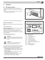
1
4
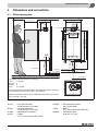
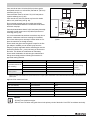
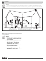
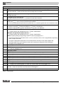
Dimensions and connections
4.2
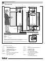
With pump group
16.5" (420 mm)
18.3” (465 mm)
0.25” (6 mm)
0
20.5” (520 mm)
0
6” (152 mm)
1.2” (30 mm)
20.5" (520 mm)
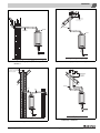
A
A/B
B
4.1” (103.5 mm)
D/F
G
E
16” (406 mm)
39.5” (1003 mm)
40,55” (1030 mm)
51.6” (1310 mm)
38.58” (980 mm)
5.3” (135 mm)
50.4” (1280 mm)
C
D
E
F
G
24.8” (630 mm)
H/J
1.4” (35 mm)
1.54” (39 mm)
5.4” (138 mm)
6.4” (162 mm)
5.1” (130 mm)
G
H
I
5.1” (130 mm)
J
5.5” (140 mm)
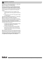
The required permanent clearances (closet) are:
in front:
1” (25 mm)
right side:
0
left side:
0
above:
6” (152 mm)
The position selected for installation MUST allow adequate space for servicing
in front of the boiler of at least 16.5” + 20.5” = 37” (940 mm).
Maintain an installation clearance from combustible construction from hot water
piping of at least 1" (25 mm).
Fig. 3
1
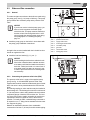
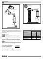
Dimensions and connections with pump group
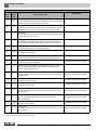
The pump group is an accessory.
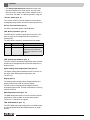
A (LA)
B (AA)
C (WB)
D (VK)
E (GAS)
12
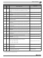
= Flue gas connection;
inside diameter 4” (100 mm)
= Air intake connection;
inside diameter 4” (100 mm)
= Wall Bracket (not shown)
= Supply;
G1½’’ union nut with female thread
= Gas connection to boiler;
Rp1’’ female thread
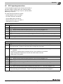
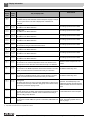
F (RK)
G (AKO)
H (PF)
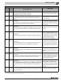
I
J (PR)
= Return;
G1½’’ union nut with female thread
= Condensate outlet;
Ø 32 mm (1¼”) O/D
= Pump group supply;
G1½’’ male thread, flat seal
= Gas connection to pump group;
1” NPT female thread
= Pump group return;
G1½’’ male thread, flat seal
Logamax plus GB162-80 kW/100 kW - Subject to modifications resulting from technical improvements!