1
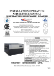
GE Infrastructure
Sensing
Model C-RV
Ultrasonic Flow Transducer
Installation Guide
GE Infrastructure
Sensing
Model C-RV
Ultrasonic Flow Transducer
Installation Guide
916-078A
October 2004
October 2004
Table of Contents
Introduction . . . . . . . . . . . . . . . . . . . . . . . . . . . . . . . . . . . . . . . . . . . . . . . . . . . . . . . . . . . . . . . . . . . . . . . . . . . . . . . . . 1
Transducer Construction . . . . . . . . . . . . . . . . . . . . . . . . . . . . . . . . . . . . . . . . . . . . . . . . . . . . . . . . . . . . . . . . . . . . . 1
Dampening Material . . . . . . . . . . . . . . . . . . . . . . . . . . . . . . . . . . . . . . . . . . . . . . . . . . . . . . . . . . . . . . . . . . . . . . . . . 2
Installing the C-RV Transducers . . . . . . . . . . . . . . . . . . . . . . . . . . . . . . . . . . . . . . . . . . . . . . . . . . . . . . . . . . . . . . . 3
Choosing an Installation Location . . . . . . . . . . . . . . . . . . . . . . . . . . . . . . . . . . . . . . . . . . . . . . . . . . . . . . . . . 4
Obtaining the Transducer Spacing . . . . . . . . . . . . . . . . . . . . . . . . . . . . . . . . . . . . . . . . . . . . . . . . . . . . . . . . 5
Installing the V Series Clamping Fixtures and Transducers. . . . . . . . . . . . . . . . . . . . . . . . . . . . . . . . . . 6
Tools and Equipment Needed . . . . . . . . . . . . . . . . . . . . . . . . . . . . . . . . . . . . . . . . . . . . . . . . . . . . . . . . . 6
Setting the Transducer Spacing . . . . . . . . . . . . . . . . . . . . . . . . . . . . . . . . . . . . . . . . . . . . . . . . . . . . . . . 7
Installing the Fixture . . . . . . . . . . . . . . . . . . . . . . . . . . . . . . . . . . . . . . . . . . . . . . . . . . . . . . . . . . . . . . . . . 9
Preparing the Pipe . . . . . . . . . . . . . . . . . . . . . . . . . . . . . . . . . . . . . . . . . . . . . . . . . . . . . . . . . . . . . . . . . . 12
Applying the DMP-1 Dampening Material . . . . . . . . . . . . . . . . . . . . . . . . . . . . . . . . . . . . . . . . . . . . 14
Applying DMP-3 Compound . . . . . . . . . . . . . . . . . . . . . . . . . . . . . . . . . . . . . . . . . . . . . . . . . . . . . . . . . 16
Applying the Pipe Dampening Jacket - PDJ . . . . . . . . . . . . . . . . . . . . . . . . . . . . . . . . . . . . . . . . . . . 18
Mounting the Transducers . . . . . . . . . . . . . . . . . . . . . . . . . . . . . . . . . . . . . . . . . . . . . . . . . . . . . . . . . . . 20
Maintenance. . . . . . . . . . . . . . . . . . . . . . . . . . . . . . . . . . . . . . . . . . . . . . . . . . . . . . . . . . . . . . . . . . . . . . . . . . . . . . . . 23
Specifications. . . . . . . . . . . . . . . . . . . . . . . . . . . . . . . . . . . . . . . . . . . . . . . . . . . . . . . . . . . . . . . . . . . . . . . . . . . . . . . 24
iii
October 2004
Warranty
Each instrument manufactured by GE Infrastructure Sensing, Inc. is
warranted to be free from defects in material and workmanship.
Liability under this warranty is limited to restoring the instrument to
normal operation or replacing the instrument, at the sole discretion of
GE Infrastructure Sensing, Inc. Fuses and batteries are specifically
excluded from any liability. This warranty is effective from the date of
delivery to the original purchaser. If GE Infrastructure Sensing, Inc.
determines that the equipment was defective, the warranty period is:
• one year for general electronic failures of the instrument
• one year for mechanical failures of the sensor
If GE Infrastructure Sensing, Inc. determines that the equipment was
damaged by misuse, improper installation, the use of unauthorized
replacement parts, or operating conditions outside the guidelines
specified by GE Infrastructure Sensing, Inc., the repairs are not
covered under this warranty.
The warranties set forth herein are exclusive and are in lieu of
all other warranties whether statutory, express or implied
(including warranties of merchantability and fitness for a
particular purpose, and warranties arising from course of
dealing or usage or trade).
Return Policy
If a GE Infrastructure Sensing, Inc. instrument malfunctions within the
warranty period, the following procedure must be completed:
Notify GE Infrastructure Sensing, Inc., giving full details of the
problem, and provide the model number and serial number of the
instrument. If the nature of the problem indicates the need for
factory service, GE Infrastructure Sensing, Inc. will issue a RETURN
AUTHORIZATION number (RA), and shipping instructions for the
return of the instrument to a service center will be provided.
If GE Infrastructure Sensing, Inc. instructs you to send your
instrument to a service center, it must be shipped prepaid to the
authorized repair station indicated in the shipping instructions.
Upon receipt, GE Infrastructure Sensing, Inc. will evaluate the
instrument to determine the cause of the malfunction.
Then, one of the following courses of action will then be taken:
• If the damage is covered under the terms of the warranty, the
instrument will be repaired at no cost to the owner and returned.
• If GE Infrastructure Sensing, Inc. determines that the damage is not
covered under the terms of the warranty, or if the warranty has
expired, an estimate for the cost of the repairs at standard rates
will be provided. Upon receipt of the owner’s approval to proceed,
the instrument will be repaired and returned.
1.
2.
3.
iv
October 2004
Introduction
Transducer
Construction
The C-RV clamp-on ultrasonic flow transducers are used exclusively
with the GE Infrastructure Sensing line of ultrasonic flowmeters.
These transducers are used to measure the flow of various gases
through pipes having diameters from less than 2 in. (50 mm) to 12 in.
(300 mm). Such measurements are independent of the pipe material.
This document provides details on the following topics:
•
Transducer Construction
•
Dampening Material
•
Installation
•
Maintenance
•
Specifications
A transducer assembly includes a 316 stainless steel housing with a
plastic wedge attached and a BNC type electrical connector. The
transducer features integral 3/4” NPT-M threads for mounting a
junction box and integral 5/8-24 threads for mounting a submersible
connector if desired, see Figure 1 below.
Figure 1: Transducer Assembly (ref dwg 536-023)
C-RV Ultrasonic Flow Transducers Installation Guide
1
October 2004
Dampening Material
GE Infrastructure Sensing strongly recommends applying DMP
dampening material in all permanent clamp-on applications to help
eliminate noise. The following dampening materials are available:
•
The DMP-1 self-adhesive sheet for applications up to 200°F
(93°C). The material comes as two 9.5-in. (24 cm) wide sheets
cut in sufficient length for your application. (Length ≈ twice the
circumference of the pipe at the installation site.)
•
The DMP-3 is a compound for applications over 150°F (65oC).
The compound is applied to the pipe with a putty knife.
•
Pipe Dampening Jacket (PDJ) is a sheath/jacket with DMP-3
pre-applied to the inside and is also used for applications over
150oF (65oC). The PDJ is available for pipes 4”, 6”, 8”, 10” and
12” (100, 150, 200, 250 and 300 mm) in diameter.
At a minimum, you should consider applying dampening material if
you have any of the following conditions:
•
The distance from the nearest butt weld or pipe flange is less
than 10 ft (3 m).
•
The pipe size is under 16 in. (400 mm) diameter and the gas
pressure is 200 psig (1,378 kPa) or lower.
•
The pipe is deformed (non-circular).
•
The pipe is old, with a history of scaling or rust.
•
The pipe experiences constant condensation on the outside.
Note: Consult a GE Infrastructure Sensing flowmeter applications
engineer or sales engineer if you have any questions
regarding dampening material.
Details for properly installing the dampening material are discussed
in the installation instructions.
2
C-RV Ultrasonic Flow Transducers Installation Guide
October 2004
Installing the C-RV
Transducers
GE Infrastructure Sensing offers the following fixtures to suit your
applications needs:
•
V4 clamping fixture
•
V8 clamping fixture
•
V12 clamping fixture
Figure 2 (below) shows the V4, V8 and V12 fixture assemblies. Each
type of transducer and fixture requires the installation of dampening
material for acoustic isolation.
Complete the steps in the following sections to position and install the
transducers, fixtures and dampening material.
V8 Fixture
V4 Fixture
V12 Fixture
Figure 2: The V4, V8 and V12 Fixtures
C-RV Ultrasonic Flow Transducers Installation Guide
3
October 2004
Choosing an Installation
Location
1. Locate the transducer measurement point at least 3 ft (1 m) from
any butt welds or flanges, ideally in the center of a 20 ft (6 m)
length of straight run of pipe. Keep appropriate clearance on either
side of the pipe for easy transducer installation:
•
6 in. (15 cm) if you are not using a junction box, or
•
9 in. (23 cm) if you are using a junction box.
Note: To guarantee the specified accuracy of the flowmeter there is
no substitute for straight run and fully-developed flow profile.
However, if straight run is not available, the transducer
location should be in a position such that the acoustic signal
travels through the full distribution of the under-developed
flow profile for best repeatability.
2. Place the transducers as close as possible to the horizontal plane.
Locate the transducers on opposite sides of the pipe 180o apart,
ideally at the 3 and 9 o’clock positions. Do not place transducers
on the top or bottom of the pipe.
Pipe
Transducer
Signal Path
End View
4
C-RV Ultrasonic Flow Transducers Installation Guide
October 2004
Obtaining the
Transducer Spacing
Enter the required information into the flowmeter’s user program
(Pipe Parameters menu) to determine the transducer spacing. Some
applications may require you to conduct a pipe survey before you can
obtain the transducer spacing. Refer to Obtaining the Transducer
Spacing section of your User’s Manual or Startup Guide for more
details.
IMPORTANT: To maintain ATEX certification the transducer face
must be protected against impact. This is provided by
properly installing the transducer into the clamping
fixture. All care must be provided during installation
to ensure all protection is afforded.
C-RV Ultrasonic Flow Transducers Installation Guide
5
October 2004
Installing the V Series
Clamping Fixtures and
Transducers
Installing the V Series clamping fixture and transducers requires the
following steps:
•
Setting the Transducer Spacing
•
Installing the Fixture
•
Preparing the Pipe
•
Applying the Dampening Material
•
Mounting the Transducers
Refer to the following section to properly prepare for installation
Tools and Equipment
Needed
Installing the fixture and transducers requires various tools. You will
also need additional tools to apply the dampening material. Refer to
Table 1 below for a complete list of everything you will need.
Table 1: Tools for V Series Fixture Installation
Fixture and Transducers
•
•
•
•
•
•
•
•
straight edge ruler/scale
•
•
thread sealant (for junction boxes only)
•
1 in. crescent/box wrench or 10 in. adjustable wrench
•
other safety equipment suitable for your application
permanent marker
sandpaper
file
emery cloth
ultrasonic thickness gage
tape measure
dry towel or rag
7/16 in. crescent/box wrench or 4 in. adjustable wrench
DMP-1
•
6
utility knife
DMP-3
•
•
gloves
putty knife or
other utensil to
remove access
dampening
compound
PDJ
•
7/16 in. crescent/
box wrench or 4
in. adjustable
wrench
C-RV Ultrasonic Flow Transducers Installation Guide
October 2004
Setting the Transducer
Spacing
1. If necessary, assemble the fixture as shown below. Make sure the
zero points on each ruler are at the same end of the fixture as
shown below.
Insert in 4 places
Top View
Zero Points
2. Using a ruler (or the ruler printed on the fixture), set one of the
mounting blocks at least 1 in. (2.5 cm) from the edge of the
fixture. To move the block, loosen the set screw, slide the block to
the desired location and tighten the set screw. Use the edge of the
block shown below as the setting point.
Zero Point on
Measuring Scales
Mounting Block
Set at 1 in. (2.5 cm)
Set Screw
Set at 1 in. (2.5cm) using
this edge of block
Top View
C-RV Ultrasonic Flow Transducers Installation Guide
7
October 2004
Setting the Transducer
Spacing (cont.)
3. Slide the other mounting block to the calculated spacing plus
1 in. (2.5 cm). For example:
a. Spacing for the first mounting block = 1 in. (2.5 cm)
b. Spacing as calculated by the flowmeter = 0.5 in. (12.5 mm)
c. Second mounting block final location = 1 in. + 0.5 in. = 1.5 in.
(2.5 cm + 1.25 cm = 3.75 cm)
The overall spacing between blocks should be left edge to left edge,
or right edge to right edge.
Note: If possible, the second block should also be set at least 1 in.
(2.5 cm) from the edge of the fixture.
Zero Point on
Set second block
Measuring Scales
using this edge
S
Top View
8
C-RV Ultrasonic Flow Transducers Installation Guide
October 2004
Installing the Fixture
During this procedure you will be required to place the fixture and
transducers on the pipe more than once, and in some cases, as many
as 3 times. The fixture and transducers are placed on the pipe
temporarily for two purposes:
•
to mark where the fixture and transducers make contact with
the pipe so those sections can be cleaned; and,
•
as a reference for placing the dampening material.
Use the steps below to begin installation:
1. Remove any pipe insulation from the installation site.
Note: Make sure you clear an area that is large enough for the
transducers and dampening material installation.
2. Disassemble the fixture by removing the four nuts from the
threaded rods and pulling apart the two halves of the fixture.
Note: Make note of the assembled fixture to make sure you
reassemble it the same way. Otherwise, the transducer
spacing will be incorrect.
Remove 4 places
Top View
C-RV Ultrasonic Flow Transducers Installation Guide
9
October 2004
Installing the Fixture
(cont.)
3. Position the clamping fixture as close as possible to the horizontal
plane. The fixture should be positioned so the transducers will be
located on the opposite sides of the pipe 180o apart, ideally at the 3
and 9 o’clock positions. For best profile identification in limited
straight run, place transducers at 1 and 7 o’clock. Do not place
fixture on the pipe so the transducers are the top or bottom of
the pipe
Note: Make sure you reassemble the fixture properly to ensure the
correct transducer spacing. If the fixture has rulers on the
rails, make sure the zero points on each ruler are at the same
end of the fixture as shown below.
Mating Half
Top View
Zero on Each
Measuring Scales
Top View
10
C-RV Ultrasonic Flow Transducers Installation Guide
October 2004
Installing the Fixture
(cont.)
4. Install the four nuts onto the threaded rods with the convex side of
the nut facing the fixture. Hand tighten each nut evenly as shown
below. DO NOT use a cross-tightening pattern.
Nuts
Nuts
(2 places)
(2 places)
Top View
Tightening Pattern of Bolts
Tighten equally first
C-RV Ultrasonic Flow Transducers Installation Guide
Tighten equally second
2
3
1
4
Side View
11
October 2004
Preparing the Pipe
1. Using a permanent marker, mark the inside edges of the fixture.
These lines indicate where to clean the pipe and then apply the
dampening material. Make sure you mark both sides of the fixture.
Make marks here
and here
Top View
2. Remove the fixture.
Marks
Top View
12
C-RV Ultrasonic Flow Transducers Installation Guide
October 2004
Preparing the Pipe
(cont.)
3. Clean the area between the marks. Remove any loose paint or rust
with sandpaper or emery cloth. Make sure to preserve the original
curvature of the pipe. If the finish is mirror-smooth, use the file to
roughen the surface.
TIP: If you are concerned about removing the reference lines
during cleaning, use a tape measure and measure 2 ft (60 cm)
from one of the reference lines and mark another line (temporary
or permanent). This line can be used as a reference point later.
4. Using an emery cloth, clean the cleared area. Again, take care to
preserve the original curvature of the pipe.
5. With an ultrasonic thickness gage, measure the pipe thickness at a
minimum of six spots on the cleared area. Take at least three
measurements at each spot and average the results to ensure
accuracy. The thickness should not vary by more than 5% among
the six spots. If you encounter more than a 5% variation, move to
another section of the pipe. Verify that the wall thickness at both
transducer locations has less than the 5% variation.
What’s Next?
The next series of steps depends on what type of dampening material
you are using. If you are using:
•
DMP-1, proceed to the next section on the next page.
•
DMP-3, proceed to page 16.
•
PDJ, proceed to page 18.
C-RV Ultrasonic Flow Transducers Installation Guide
13
October 2004
Applying the DMP-1
Dampening Material
1. Unroll the DMP-1 material and peel back a small part of the paper
backing. Do not completely remove the paper backing. One 9.5-in.
(24-cm) roll fits between the lines marked on the pipe.
2. Use a dry towel or rag and dry the pipe.
IMPORTANT: The dampening material will only adhere to the pipe
correctly if the pipe is completely dry.
3. Roll the DMP-1 dampening material around the pipe, peeling the
paper backing off as you go. Place the material between the marks
that represent the inside edge of the fixture, as shown below. Use
the entire length supplied, wrapping the material over itself.
4. Reinstall the fixture making sure the fixture is reassembled
correctly to ensure the correct transducer spacing (see Installing
the Fixture, beginning with step 3 on page 10).
5. Loosely mount the transducers on top of the dampening material.
6. With a marker, trace around the transducer footprint. Remove the
fixture and transducers.
14
C-RV Ultrasonic Flow Transducers Installation Guide
October 2004
Applying DMP-1
Dampening Material
(cont.)
7. Use a utility knife to cut out the area under the transducer
footprint. Peel the cut material off the pipe, as shown below.
8. Reinstall the fixture on the pipe (see Installing the Fixture,
beginning with step 3 on page 10). Once the fixture is on the pipe,
tighten the four nuts with a 1-in. crescent/box wrench. DO NOT
use a cross-tightening pattern.
9. Use the second strip of dampening material for additional
dampening. Unroll the second strip of dampening material and cut
the strip into two pieces, each 4.5-in. (11 cm) wide.
10.Wrap each of these strips around the pipe on the outside edge of
the clamping fixture, one upstream and one downstream. The
completed dampening material installation should appear similar
to the figure below (with transducers).
11. To mount transducers, refer to Mounting the Transducers page 20.
C-RV Ultrasonic Flow Transducers Installation Guide
15
October 2004
Applying DMP-3
Compound
!WARNING!
BE SURE TO WEAR PROPER EYE
AND SKIN PROTECTION WHEN APPLYING THE
DAMPENING COMPOUND. ALSO MAKE
SURE THERE IS PROPER VENTILATION
1. Use a dry towel or rag and dry the pipe.
IMPORTANT: The dampening material will only adhere to the pipe
correctly if the pipe is completely dry.
!WARNING - HIGH TEMPERATURE APPLICATIONS!
ONCE THE DAMPENING COMPOUND IS APPLIED TO THE
PIPE, THE COMPOUND MAY DRIP AND
WILL CAUSE SEVERE BURNS UPON
CONTACT WITH BARE SKIN. ALSO, BE SURE
NOT TO INHALE THE FUMES GENERATED
DURING THE DMP-3 CURING CYCLE.
2. Wearing gloves, place a piece of the DMP-3 material on top of the
pipe and use the palm of the hand to press it onto the pipe.
Note: If the measurement point is near a flange or weld, apply
DMP-3 between that structure and the fixture as well.
3. Spread the DMP-3 material so that it covers the whole area under
the fixture to a thickness of about 0.25 in. (6 mm).
16
C-RV Ultrasonic Flow Transducers Installation Guide
October 2004
Applying DMP-3
Compound (cont.)
4. Reinstall the fixture around, but not on, the DMP-3 material
making sure the fixture is reassembled properly to ensure the
correct transducer spacing. (see Installing the Fixture, beginning
with step 3 on page 10). Once the fixture is on the pipe, tighten the
four nuts with a 1-in. crescent/box wrench. DO NOT use a crosstightening pattern.
5. Using a putty knife or other utensil, remove the DMP-3 material
from the transducer locations.
6. To mount transducers, refer to Mounting the Transducers page 20.
C-RV Ultrasonic Flow Transducers Installation Guide
17
October 2004
Applying the Pipe
Dampening Jacket - PDJ
!WARNING!
BE SURE TO WEAR PROPER EYE AND SKIN PROTECTION
WHEN APPLYING THE DAMPENING COMPOUND. ALSO
MAKE SURE THERE IS PROPER VENTILATION
1. Remove the backing from the inside of the pipe dampening jacket.
!WARNING - HIGH TEMPERATURE APPLICATIONS!
ONCE THE DAMPENING COMPOUND IS APPLIED TO THE
PIPE, THE COMPOUND MAY DRIP AND WILL CAUSE
SEVERE BURNS UPON CONTACT WITH BARE SKIN. ALSO,
BE SURE NOT TO INHALE THE FUMES GENERATED
DURING THE DMP-3 CURING CYCLE.
2. Install the jacket on the pipe so the jacket is between the marks
and the transducer holes are located at the 3 and 9 o’clock
positions.
Note: GE Infrastructure Sensing recommends placing the PDJ on
the pipe so the seam is as close to the of the pipe as possible.
Placing the seam at the top of the pipe reduces the amount of
dripping.
3. Tighten the clamping screws evenly in sequence (see figure
below) taking care not to twist or warp the PDJ. When tightening,
some fluid and dampening material will drip from the bottom of
the jacket.
Note: As the dampening material dries out over several hours after
installation, its effectiveness increases.
1
2
3
4
Tighten in sequence
18
C-RV Ultrasonic Flow Transducers Installation Guide
October 2004
Applying the Pipe
Dampening Jacket - PDJ
(cont.)
4. Install the fixture over the jacket (see Installing the Fixture,
beginning with step 3 on page 10), adjusting the fixture so the
transducer block falls over the pre-stamped transducer holes at the
flowmeter spacing calculations. The figure below shows the PDJ
and the fixture with transducers.
Note: Make sure the fixture is reassembled properly to ensure the
correct transducer spacing.
5. Once the fixture is on the pipe, tighten the four nuts with a 1-in.
crescent/box wrench. DO NOT use a cross-tightening pattern.
6. To mount transducers, refer to Mounting the Transducers page 20.
C-RV Ultrasonic Flow Transducers Installation Guide
19
October 2004
Mounting the
Transducers
If your application:
•
requires junction boxes, refer to step 1 below.
•
does not require junction boxes, skip to step 3.
Note: Dampening material is not shown in the following
illustrations.
1.
Apply a thread sealant to the transducer threads. A sealant is not
required within the U.S., however, a sealant must be used in
European Communities.
2.
Before mounting the transducers, thread the junction box onto
the end of the transducer with the BNC connector. Ensure that at
least five full threads are engaged. Make sure to orient the cover
of the junction box so it is accessible to make cable connections
once the box is installed.
3. Apply a bead of couplant 0.25 in. (6 mm) wide along the entire
length of each transducer face. The purpose of the couplant is to
expel the air gap between the transducer and the pipe. Air will
cause the transducer signal to attenuate.
IMPORTANT: To prevent the loss of couplant, do not slide the
transducer with couplant along the surface of the
pipe when mounting.
4. If you are using:
20
•
CPL-1, CPL-2 or CPL-3, proceed to the next step.
•
CPL-16, proceed to step 7 on the next page.
C-RV Ultrasonic Flow Transducers Installation Guide
October 2004
Mounting the
Transducers (cont.)
5. Insert the transducers into the mounting blocks, making sure the
BNC connectors (or junction boxes) point away from the center of
the fixture. Tighten the pressure bolts to hold the transducers in
place. Hand tighten the bolt enough so the transducer makes
contact with the pipe.
IMPORTANT: Do not use a wrench or pliers on the pressure bolt.
Pressure Bolt
Transducer
Top View
6. Skip to step 10 on the next page.
7. Install the transducers into the mounting blocks. Use the pressure
bolt to hold the transducer in place while the couplant begins to
spread. Wait 1 minute.
IMPORTANT: Do not use a wrench or pliers on the pressure bolt.
8. Turn the pressure bolt 1/4 turn and wait 1 minute again. Do not
overtighten so that the fixture lifts off the pipe.
9. Repeat step 8 once; then, proceed to the next step.
C-RV Ultrasonic Flow Transducers Installation Guide
21
October 2004
Mounting the
Transducers (cont.)
10. For permanent applications, tighten the locking nut with a
wrench to maintain constant pressure and prevent loosening due
to vibration and thermal expansions.
Locking Nut
Top View
What’s Next?
You have completed installing the V Series Clamping Fixture and
transducers. You should do the following:
22
•
Refer to the installation section of your User’s Manual or
Startup Guide to make transducer connections.
•
Make a note of the installation date and set a schedule for
periodic inspection and tightening of clamping fixture nuts to
ensure clamping fixture does not become loose and fall,
possibly causing injury.
•
Once the flowmeter is up and running, measure the signal
strength of each transducer using the flowmeter’s diagnostics
menu and make a note of it. This value will be helpful when
making periodic checks. Refer to your User’s Manual or
Startup Guide for more details.
C-RV Ultrasonic Flow Transducers Installation Guide
October 2004
Maintenance
Transducers, couplant, the clamping fixture and dampening material
are provided by GE Infrastructure Sensing. Once you have completed
installation little maintenance is required. Refer to Table 2 below for
maintenance information.
Table 2: Maintenance Checks
Maintenance Check
Component
Interval
Comments
Transducer
N/A
Couplant
Verify every 6 months
in dry areas (e.g. the
desert).
Dampening
Material
N/A
Life of 25 years. Consult factory No cleaning required.
for additional information if
needed.
Clamping
Fixture
Determined by user.
Periodic inspection and
tightening of clamping fixture
nuts is required to ensure
clamping fixture does not
become loose and fall, possibly
causing injury.
No cleaning required.
No additional adjustments or
maintenance needed. If you
suspect something is wrong with
a transducer or need to replace a
transducer, simply loosen the
pressure bolt that secures the
transducer in place and remove
it. If necessary, loosen the
locking nut with a wrench. Refer
to the appropriate section to
insert a new transducers.
No cleaning required.
Measure the signal strength
using diagnostics and compare
to the value taken at the time of
installation. Good and bad limits
Verify every 12 months are listed in the Service Manual
or User’s Manual.
in other areas.
C-RV Ultrasonic Flow Transducers Installation Guide
No cleaning required.
23
October 2004
Specifications
Table 3: C-RV Transducer Specifications
Transducer No.
Primary Use
Installation Type
Material of Construction
310
Mid size pipes
Clamp on
316 SS and plastic
Pipe Sizes
> 2” to 12” (>50 to 300 mm)
Clamping Fixture
CFG-V4, CFG-V8, CFG-12
Operating Frequency
Electrical Rating
Ambient
Temperature
Range
Process Temp. Range
500 kHz
200 V peak-to-peak, 5 mA
North America:
-20 to +75°C (-4 to +167°F)
Europe:
-40 to +75°C (-40 to +167°F)
-40 to 130oC (-40 to 266oF)
North American
Certification Explosion proof
Class I, Div 1,
Group B, C, D
European Certification Flameproof
II 2 GD, EEx md IIC
T6
Tamb -40 to 75oC (-40 to 167oF)
KEMA 02ATEX2337 X
North American
Certification Weatherproof
IP66, TYPE 4X
200Vpp, 5mA
European Certification Weatherproof
IP 66
IMPORTANT: The transducer is protected by a suitable fuse
located in the flowmeter electronics. The fuse has a
breaking capacity in accordance with the short
circuit current of the supply.
24
C-RV Ultrasonic Flow Transducers Installation Guide
DECLARATION
OF
CONFORMITY
GE Infrastructure
Sensing
We,
declare under our sole responsibility that the
Panametrics Limited
Shannon Industrial Estate
Shannon, County Clare
Ireland
CRL Ultrasonic Flow Transducer
CRS Ultrasonic Flow Transducer
CRV Ultrasonic Flow Transducer
CRW Ultrasonic Flow Transducer
to which this declaration relates, are in conformity with the following standards:
•
•
•
•
•
EN 50014:1997+A1+A2:1999
EN 50018:2000
EN 50028:1987
EN 50281-1-1:1998
II 2 GD EEx md IIC T6
KEMA02ATEX2337 X
KEMA03ATEX1540 X
KEMA, Ultrechtseweg, 310 Arnhem, The Netherlands
• EN 61326:1998, Class A, Annex A, Continuous Unmonitored Operation
CRL , CRS, CRV:
CRW:
following the provisions of the 89/336/EEC EMC Directive and the 94/9/EC ATEX Directive.
Shannon - July 1, 2003
Mr. James Gibson
GENERAL MANAGER
TÜV
TÜV ESSEN
ISO 9001
U.S.
CERT-DOC-H0
August 2004
DECLARATION
DE
CONFORMITE
GE Infrastructure
Sensing
Panametrics Limited
Shannon Industrial Estate
Shannon, County Clare
Ireland
Nous,
déclarons sous notre propre responsabilité que les
CRL Ultrasonic Flow Transducer
CRS Ultrasonic Flow Transducer
CRV Ultrasonic Flow Transducer
CRW Ultrasonic Flow Transducer
rélatif á cette déclaration, sont en conformité avec les documents suivants:
•
•
•
•
•
EN 50014:1997+A1+A2:1999
EN 50018:2000
EN 50028:1987
EN 50281-1-1:1998
II 2 GD EEx md IIC T6
KEMA02ATEX2337 X
KEMA03ATEX1540 X
KEMA, Ultrechtseweg, 310 Arnhem, The Netherlands
• EN 61326:1998, Class A, Annex A, Continuous Unmonitored Operation
CRL , CRS, CRV:
CRW:
suivant les régles de la Directive de Compatibilité Electromagnétique 89/336/EEC et d’ATEX 94/9/EC.
Shannon - July 1, 2003
Mr. James Gibson
DIRECTEUR GÉNÉRAL
TÜV
TÜV ESSEN
ISO 9001
U.S.
CERT-DOC-H0
August 2004
GE Infrastructure
KONFORMITÄTS-
Sensing
ERKLÄRUNG
Panametrics Limited
Shannon Industrial Estate
Shannon, County Clare
Ireland
Wir,
erklären, in alleiniger Verantwortung, daß die Produkte
folgende Normen erfüllen:
CRL Ultrasonic Flow Transducer
CRS Ultrasonic Flow Transducer
CRV Ultrasonic Flow Transducer
CRW Ultrasonic Flow Transducer
•
•
•
•
•
EN 50014:1997+A1+A2:1999
EN 50018:2000
EN 50028:1987
EN 50281-1-1:1998
II 2 GD EEx md IIC T6
CRL, CRS, CRV: KEMA02ATEX2337 X
CRW: KEMA03ATEX1540 X
KEMA, Ultrechtseweg, 310 Arnhem, The Netherlands
• EN 61326:1998, Class A, Annex A, Continuous Unmonitored Operation
gemäß den Europäischen Richtlinien, Niederspannungsrichtlinie EMV-Richtlinie Nr.: 89/336/EG und ATEX Richtlinie
Nr. 94/9/EG.
Shannon - July 1, 2003
Mr. James Gibson
GENERALDIREKTOR
TÜV
TÜV ESSEN
ISO 9001
U.S.
CERT-DOC-H0
August 2004
GE Infrastructure
ATEX COMPLIANCE
Sensing
We,
GE Infrastructure Sensing, Inc.
1100 Technology Park Drive
Billerica, MA 01821-4111
U.S.A.
as the manufacturer, declare under our sole responsibility that the product
Type C-RV Ultrasonic Flow Transducer
to which this document relates, in accordance with the provisions of ATEX Directive 94/9/EC Annex II, meets the
following specifications:
1180
II 2 GD EEx md IIC T6
KEMA02ATEX2337X T80°C, -40°C to +75°C
Furthermore, the following additional requirements and specifications apply to the product:
• Having been designed in accordance with EN 50014, EN 50018, EN 50281 and EN 50028, the product meets the
fault tolerance requirements of electrical apparatus for categories “d” and “m”.
• Only trained, competent personnel may install, operate and maintain the equipment.
• The product is an electrical apparatus and must be installed in the hazardous area in accordance with the
requirements of the EC Type Examination Certificate. The installation must be carried out in accordance with all
appropriate international, national and local standard codes and practices and site regulations for flameproof
apparatus and in accordance with the instructions contained in the manual. Access to the circuitry must not be
made during operation.
• The product has been designed so that the protection afforded will not be reduced due to the effects of corrosion
of materials, electrical conductivity, impact strength, aging resistance or the effects of temperature variations.
• The product cannot be repaired by the user; it must be replaced by an equivalent certified product. Repairs should
only be carried out by the manufacturer or by an approved repairer.
• The product must not be subjected to mechanical or thermal stresses in excess of those permitted in the
certification documentation and the instruction manual.
• The product contains no exposed parts which produce surface temperature infrared, electromagnetic ionizing, or
non-electrical dangers.
• The product must be protected by a suitable fuse. The breaking capacity of the fuse must be in accordance with
the prospective short circuit current of the supply.
• The product must be installed in such a way that its front face is protected against impact.
• Installation Instructions: The product is provided with a male 3/4” NPT thread. For electrical connection, the
product must be mounted to a certified metal enclosure in type of explosion protection flameproof enclosure “d”,
the assembly complying with the requirements of EN50018 and providing a degree of protection of IP6X.
Measures must be taken to ensure a good bonding connection and to prevent the connection from self-loosening.
CERT-ATEX-D (Rev. August 2004)
USA
GE Infrastructure Sensing
221 Crescent Street, Suite 1
Waltham, MA 02453-3497
Telephone: (781) 899-2719
Toll-free: (800) 833-9438
Fax: (781) 894-8582
E-Mail: [email protected]
Web: www.gepower.com/panametrics
Ireland
GE Infrastructure Sensing
Shannon Industrial Estate
Shannon, County Clare
Ireland
Telephone: 353-61-470200
Fax: 353-61-471359
E-Mail: [email protected]