1
4
ELECTRICAL WIRING
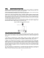
All electrical wiring to the boiler must be electrically bonded to ground in accordance with the
requirements of the authority having jurisdiction or, in the absence of such requirements, with the National
Electrical Code, ANSI/NFPA 70 or the Canadian Electrical Code Part I, CSA C22.1, Electrical Code.
Provide disconnecting means of sufficient rating within sight of the boiler. These heaters require an 115V,
60Hz supply. Depending on the pump used, a 15-amp breaker is usually sufficient.
Electrical connections must be made so that the circulator will operate before the gas valve can open. At
no time may the control system allow the burner to fire without water flowing in the system.
Use minimum 18-gauge conductor for 24-volt field wiring to boiler. Splicing of wires is not recommended.
Use sealed tight conduit suitable for outdoor use for outdoor installations. Use terminal strip provided
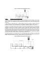
inside control panel for low water cut-off and remote controller. Refer to wiring diagram provided with
boiler.
5
MODULATION SEQUENCE
Models 300 through 600 are supplied with a modulating fan which pressurizes the space below the
combustion chamber and feeds air to the venturi connected to the air/gas mix tube.
Before the appliance can light off, the air proving switch must be closed and the pilot must be lit. The
blocked flue switch is normally closed and opens only under blocked air or blocked flue conditions. All
models are supplied with a single burner.
Each MicoFlame is supplied with the appropriate wiring diagram showing the sequence provided as well
as any special controls or options requested.
When converting multiple MicoFlame appliances to an external sequencing control each modulating
heater can be regarded as one stage. In this way the sequencer will lead/lag or rotate the boilers
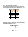
properly. One option (Mode 8 on the BTC 1) allows the remote controller to initiate and modulate the
boiler with a single 0-10V analog signal. Refer to Table 8 for details.
Pre-purge
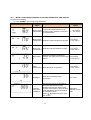
BTC 1 Modulation control activates the pre-purge cycle for 20 seconds before trial for ignition.
Ignition Trial
On proof of air flow, the air proving switch closes and energizes the ignition module. The module first
initiates a self check and then starts the pilot ignition sequence. The modulating sequence begins with the
modulating fan ramping down to ignition speed. The safety shutoff valve opens, which allows gas to flow
to the pilot burner. At the same time, the electronic spark generator in the module produces 10,000 Volt
spark pulse output. The voltage generates a spark at the igniter that ignites the pilot. If the pilot does not
light, or the pilot flame current is not at least, on average, 1.5 µA and steady, the module will not energize
the combination valve and the main burner will not light. The ignition module provides 100% gas shutoff,
followed by retry for ignition. If required (e.g. CSD-1) a module with lockout feature can be provided.
Main Burner
When the pilot flame is established, a flame rectification circuit is completed between the sensor and the
burner ground. The flame sensing circuit in the ignition module detects the flame current, shuts off the
spark generator and energizes the combination control which is a one to one air/gas ratio control valve.
As the modulating fan ramps up, gas input is adjusted accordingly to match the airflow. When the call for
heat ends, the valve is de-energized, and the fan modulates off.
4