1
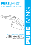
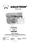
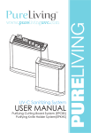
Ultrasonic Piezo Implant Surgery Service Manual >>> Surgystar DMETEC Co., Ltd SM-DM-S03 rev.0 1/21 page CONTENTS page 1. Check List 3 2. Model Name & Function 4 3. PCB Module Name & Function 4 4. Multi-Meter 5 5. Check Method 6 - 20 SM-DM-S03 rev.0 2/21 page 1. Index: check list No Problem Press ON/OFF switch, No power 1 Check Item 1. 2. 3. 4. 5. Adapter Connection Power Supply (100-240VAC, 50/60Hz) Power on/off switch Power on/off Noise Filter a. Fuse Power Part b. DC power a. Power Input 2 3 4 5 6 7 8 9 go to No. 5 1. LCD Cable Connection check 11,12,13,14 2. Main Board go to No. 5 Power Supply On, Error Message in Touch Panel 1. Touch Panel Cable Connection 2. Touch control 3. Main Board check 7 check 7,9 go to No. 5 Press Touch screen, Wrong displayed 1. Touch Control 2. Main Board check 7,8,9 go to No. 5 System Power Supply is displayed as Wrong 1.Power part Power on, LCD is not displayed with warning sound 2.Main board check 4-1,4-2, 4-3,4-4 go to No. 5 System temperature is displayed as Fail. 1.Temperature Sensor Control Part 2.Main board check 19 go to No. 5 System Fan is displayed as Fail 1.System FAN Connection 2.System FAN Control check 15,16 check 15,16 3.Main Board go to No. 5 1. Touch Panel Cable Connection 2. Touch Control Part check 7,8,9 check 7,8,9 3. Main Board go to No. 5 Piezo Module is displayed as Fail 1.Main CPU, Surgery CPU check 5, 21 2.Main Board go to No. 5 HP/TIP/Tuning is displayed as Fail 1.Tip tightened 2.Handpiece Cable Connection 3.Remained Water in the Handpiece 4.Handpiece Cable inside Line 5.Main Board go to No. 5 1.Foot Switch Connection 2.Defective Foot Switch 3.Foot Switch Control Part check 24 check 24 check 23 4.Main Board go to No. 5 1.Main CPU, Surgery CPU check 5, 21 check 1,2,3,4,4-1, 4-2,4-3,4-4 Touch System is displayed as Fail Press Foot Switch, No working Main Board is not working. 2.Power Supply 12 13 check 32 Power Supply check 3 check 4 check 1 check 2 check 4-1,4-2, 4-3,4-4 6. Main board 10 11 Check Method No Sound SM-DM-S03 rev.0 check check check check 26 29 30 31 3.Main Board go to No. 5 1.SYSTEM CONFIG SYSTEM CONFIG Menu 2.Main Board go to No. 5 3/21 page 14 Water leakage in coolant motor block during operation Water Tubing check 27,29,32 15 Coolant motor is not working during operation 1.Coolant Motor Cable Connection 2.Coolant Motor Control check 17 check 17 3.Main Board go to No. 5 1.SYSTEM CONFIG 2.LCD Control SYSTEM CONFIG Menu check 11,12,13,14 3.Main Board go to No. 5 1.Tip tightened check 26 2.Tip worn out or no water check 28 1.Handpiece Cable & Water Tubing Connection 2. Tip worn out or no water spary 3.Tip Tightened 4.Defective Handpiece 5.Main Board go to No. 5 16 17 LCD displayed screen is not clear or dark Weak Vibration Power No water spray in the tip 18 check check check check 29 28 26 31 19 Water leakage in the handpiece when stop the operation 1.Water Tubing check 32 20 Water Leakage between tip and handpiece connection 1.Tip Connection (tightened) check 26 21 Piezo Pumping Skip is displayed. 1.Program is O.K check 32 SM-DM-S03 rev.0 4/21 page 2. Item Name & Function Surgystar Main body Surgystar Parts - Foot Switch - Adaptor - Line Cord Surgystar Handpiece with cable - Handpiece with cable - Water connection Tubing -Saline Connection Tubing SM-DM-S03 rev.0 5/21 page Surgystar TIP Used with handpiece 3. PCB Module Name & Function Surgystar Mian Board - Vibration in Handpiece. - Menu in LCD Panel - Coolant motor control during operation SM-DM-S03 rev.0 6/21 page 4. Multi-Meter Multi-Meter Function Mark Indication Power OFF AC Voltage DC voltage mV voltage Resistor[ohm] Diode, short AC Ampere DC Ampere SM-DM-S03 rev.0 7/21 page 5. Check Item 1. Power Supply PCB Module Check 2 Check 3 Check 4 Check 1 Check 1 - Fuse Normal: short Abnormal replace fuse Check 2 - Jack2(DC in put) Normal: DC 24V SM-DM-S03 rev.0 8/21 page Check 3 – CON4(Power on/off switch) Normal: when power switch on, between pin 1 & 3, pin 2 & 4 are short Check 4 – DB48(Power Supply Noise Filter) Normal: when power switch on, between pin 1 & 3, pin 2 & 4 are short Check 4 – DB48(전 Power Supply Noise Filter ) Normal: when power switch on, between pin 1 & 3, pin 2 & 4 are short SM-DM-S03 rev.0 9/21 page Check 5 2. Power Control Board Check) Check 4-1 Check 4-2 Check 4-3 Check 4-4 Check 4-1 TP27 & TP45 Measure Normal: DC 5.0 ± 5%, Abnormal: check U15 Check 4-2 TP28 & GND Measure Normal: DC 36V ± 5%, Abnormal: check U17,Q6 SM-DM-S03 rev.0 10/21 page Check 4-2 TP28 & GND Measure Normal: DC 36V ± 5%, Abnormal : check U17,Q6 Check 4-3 TP31 & GND Measure Normal: DC 12V ± 5%, Abnormal : check U19 Check 4-4 TP29 & GND Measure Normal: DC -5V ± 5%, Abnormal: check U19 SM-DM-S03 rev.0 11/21 page 3. Main Board Check Check 12 Check 10 Check 7 Check 11 Check 13 Check 9 Check 5 Check 6 Check 14 Check 8 SM-DM-S03 rev.0 12/21 page Check 5 – LED 1 Normal: D1 is green signal (on/off) - Abnormal : check power supply (+5V)in U3, D1, U4, U2 - LED is no signal with sound: check D1 is broken - Check Pin 6 of U4 and Pin 20 of U20 is well connected - Check Y1,C14, C15 whether they are broken Check 7 – Touch Panel - 1 Normal: button is operated well Abnormal : - check touch panel is connected right direction - after touch panel is connected and in the press the touch panel, check TP5~TP8 & TP47 (GND),voltage will be DC 0.5 ~ 4.5V - Check 8 - Touch Panel - 2 When LCD silicon guide is out of touch panel and main body U3 Pin 27 by using pincet Check 9 - Touch Panel - 3 - - - SM-DM-S03 rev.0 Put silicon guide into the body - check pin 11 of U8 and pin 27 of U3 are connected rightly - check touch related parts are well connected and check U8 and U3 is well connected through PCB connection drawing. -if all parts are connected well, replace with new U3 part (there will be some possibility for defective U3) 13/21 page Check 10 -Display This means stand-by(ready) status and will be moved to main Manu(Surgery) soon. Check 11 -Display -1 U3 Pin 6 - - - if LCD cable is not connected, there will be long sound in short interval. This will be disappeared and well operated if LCD cable is connected. - check Contrast: -If too bright or too dark, adjust R15 (variable resistance), if R 15 is broken, replaced with new. -Check middle pin of R15 is DC -14.5V~15.5V under the LCD cable is connected. -In SYSTEM CONFIG Menu, when adjust level, check whether voltage of middle pin of R15 is changed. -If no voltage in R1,check pin 6 of U3 is well connected Check 12 -Display U3 Pin 5 - - U3 Pin 27 - -BackLight - -Check voltage in TP3(less 0.5~more 4.5V) -In SYSTEM CONFIG Menu, when adjust level, check voltage of TP3 is changed. -if there is signal in TP3 but backlight is not on, check parts of U7, Q2, Q3, R16, R18, whether they are broken and replaced with new. -if no signal in TP3, check pin 5 of U3 is well connected. -check R16, R18 is well connected with LCD cable Check 13 -Display - 3 - - SM-DM-S03 rev.0 -2 - Touch board problem: - If no display in screen with sound and well connected, there will be problem in touch board. This will be check touch program, then displayed. -Check touch board is well connected. -Check 100KOhm is connected with R22 and Pin 13 of U8 is connected with Pin 29 of U3. (refer to Check7~9) 14/21 page Check 14 Display - 4 - The trouble causes Memory, the Main CPU and Latch part connection problems. If you do not have any problem on the part of touch LCD, should make sure the circuit connection between Main CPU, memory and cable. First, make sure to mount a proper part. - Check that Oohm is equipped on Latch IC (U2) and memory (U1) and R5, except R6. - After everything has been properly equipped, look at the schematic and the DATA line connection, and each address must be verified. - Check the voltage changes on AD0 ~ AD6, nWR, nRD, CS, L_RST, LCD connector pins 15. - If more problems, check the U1, U2 part in order. Check 15 SYSTEM FAN -1 - J5 should be connected to the FAN. - In case of FAN suspended state, the voltage is above 3.0V. During operation is less than 0.5V. - You can check operation status through SYSTEM CHECK TEST & INIT menu by pressing the button. Check 16 SYSTEM FAN -2 - check whether J5 (back side) is properly connected to the FAN. - In case of FAN suspended state, the voltage of TP4 is above 3.0V. During operation is less than 0.5V. - You can check the operation status by pressing button of System check from Test&Init Menu. --In case of Fail. - Check whether the TP9 voltage changes. If does not change, make sure whether connected to pin #17. - Check the voltage change on U7 SM-DM-S03 rev.0 15/21 page #5, #6 pins. If not, check the connection or breakage of the R23, Q4, Q5, and U7. - Make sure the power is connected to FAN. #2 pin voltage of J5 (back side) should be 5V. - In case of FAN suspended state, the voltage of TP4 is above 3.0V. During operation is less than 0.5V. Check 17 Motor for Cooling Water. - Make sure motor cable is should be connected to CON2. - Pin #12 of U13 connected 5V; Pin #6 should be 24V. - Check the voltage on TP16 between 0.5V ~ 4.5V. - Make sure the voltage changes depending on the Menu. - R49 and U13 are connected to Check 19 System temperature checking pin #15. - Be sure the temperature sensor out to voltage. Temperature range is - In case of Cooling Motor is in between 0 ℃ and 100 ℃. Ex) ‘10mV per 1 ℃’, if current temperature is 24 suspended state, the voltage of #8 degrees, so it is about 240mV is measured on TP1. of U13 is below 0.5V. During The temperature can be found from the SYSTEM CHECK on the TEST & INIT operation is above than 4.5V. menu. - R52 and U13 are connected to In case of trouble, the pin #12. check whether Pins of U8IN is SHORT or OPEN. check C18, R17 is SHORT. TP1 should be connected to the PIN #57 of U3. replace U3. SM-DM-S03 rev.0 16/21 page Check 18 System Sound checking - There is sound for indicating an error message or touching the LCD, in case silence, should check system sound - Check the SYSTEM CONFIG sure to adjust the sound level should take place. -In order to determine the output voltage for sound can be measured at TP10. - Pin #8 of U10 is connected to 12V. - Check the various components or the connection status and replace the buzzer or the U10 part. Check 20 Piezo module checking - Check the communication is made properly between Main CPU and Surgery CPU. First of all, make sure the R128 is connected. Then check the voltage changes on Tp25 and TP26. Check R1, R2 is connected properly to 10Kohm. Check 21 Piezo Surgery Controller checking - 1 - Normal Status: the main board's power supply is normal, D18 flashing green - When it is not normal: check the +5 V power supply is supplied to U16, D18. - If LED is not blinking, check D18 is damaged. - Check Y2, C64, C65 is damaged. - - Foot switch press, Surgery will operate. - Foot switch does not work, and then instantly confirmed over the handpiece and drive components, make sure Surgery. The Q9, Q12, Q8, Q10, Q11, Q13, U20, U21 and is connected properly examined and tested to work. SM-DM-S03 rev.0 17/21 page Check 22 Piezo Surgery Controller checking - 2 * Note: Turn off the device before you check. (POWER OFF) - Normal case, TP41, TP42 is SHORT. Check 23 Foot Switch Checking - 1 Pressing the foot switch, depending on the type, TP14, TP15, TP19, TP21 has the voltage change. While pressed, the voltage is less than 0.5V. When you unpress switch, the voltage would be more than 4.5V. If the foot switch has not trouble on itself, check between ISO1 ~4 parts and accessories. Check 24 Foot Switch Checking - 2 Check the connection between foot switch and socket on the back If connected properly, check the foot switch according to ‘Foot Switch checking-1’ Check 25 Handpiece Cable Checking Handpiece cable connector Normal: OPEN SM-DM-S03 rev.0 18/21 page Check 26 Check the tip connection Release the tip and re-tighten by Torque-wrench. (Tighten tip until running idle.) Check 27 Check the cable and water tubing. Replace water tubing if handpiece cable or water tubing is leaking or damaged due to the long term using. Check 28 If tip wears, crack or blocked, the water does not come out. - Replace the tip if the handpiece cannot output the strong power due to aging tip. - In case there is message of ‘Piezo tuning error’, re-tighten the tip. If the message still goes on, replace the tip. - After using, make sure there shall not remain saline and debris in the handpiece. Otherwise saline could be stuck. Check 29 Check the connection between handpiece and water tubing. - Check the connection status of handpiece and Surgystar. - Check the connection status of water tube and cooling block. - Check the connection status of water tube and handpiece tube. SM-DM-S03 rev.0 19/21 page Check 30 Check water remaining in connector. Make sure no water remains in handpiece connector and main body connector. If there is water, dry it before using. Check 31 Check handpiece problem. If handpiece is not working, check the system with new handpiece to make sure problem on handpiece. Check 32 In case running water from the handpiece during no operation. Replace water tubing. Check 32 Piezo Pumping Skip. * No problem SM-DM-S03 rev.0 20/21 page Check 33 (Transformer check) 1. Check the adapter is connected device to and the power outlet 2. Sure to check the adapter is connected to the rated power 3. Normal: DC 24V by measuring multimeter as shown. SM-DM-S03 rev.0 21/21 page