1
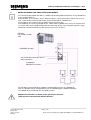
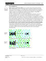
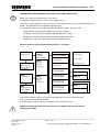
Industry Automation and Drive Technologies - SCE
Training Manual for Integrated Automation
Solutions
Totally Integrated Automation (TIA)
MODULE E11
Radio Frequency Identification (RFID)
with SIMATIC S7-300F-2 PN/DP and RF180C
TIA Training Document
Module E11
Status: 01/2010
RF180C
Page 1 of 65
Radio Frequency Identification (RFID) with SIMATIC S7-300F-2PN/DP and
Industry Automation and Drive Technologies - SCE
This manual was prepared for training purposes by Siemens AG for the project Siemens Automation Cooperates
with Education (SCE).
Siemens AG does not guarantee the contents of this document.
Passing on this document as well as copying it, using and communicating its contents is permitted within public
training and continued education facilities. Exceptions require the written permission by Siemens AG (Michael
Knust [email protected]).
Violators are held liable to pay damages. All rights -including translation- reserved, particularly if a patent is
granted, or a utility model or design is registered.
We wish to thank the Michael Dziallas Engineering corporation and the instructors of vocational schools as well
as all those who provided support during the preparation of this manual.
TIA Training Document
Module E11
Status: 01/2010
RF180C
Page 2 of 65
Radio Frequency Identification (RFID) with SIMATIC S7-300F-2PN/DP and
Industry Automation and Drive Technologies - SCE
PAGE
1
PREFACE .......................................................................................................................................................5
2
Notes regarding the usage of CPU 315F-2 PN/DP .....................................................................................7
3
Notes regarding the SIMATIC RFID components ......................................................................................8
4
RFID Fundamentals ......................................................................................................................................9
5
Starting up an RFID project with CPU 315F-2 PN/DP and RF180C ........................................................10
5.1
Setting Up a New Project .....................................................................................................................11
5.2
Configuring the Hardware ....................................................................................................................13
5.3
Assigning a Device Name ....................................................................................................................20
5.4
Inserting UDT Blocks and FB45...........................................................................................................22
5.5
Generating Data Blocks .......................................................................................................................23
5.6
Programming a Restart or Warm Restart ............................................................................................33
5.7
FC11 Function for a Command or Request .........................................................................................34
5.8
Basics of Entries at Command Block FC11 .........................................................................................36
5.9
Command String ..................................................................................................................................39
5.10
Basics of FB45 and DB45 ....................................................................................................................40
5.11
FB10 Reader_Control Program............................................................................................................51
5.12
FB1 Control Program ...........................................................................................................................55
5.13
OB1 Program Call ................................................................................................................................61
5.14
Variable Table STATUS_SLG_1..........................................................................................................62
5.15
Variable Table STATUS_SLG_2..........................................................................................................63
5.16
Symbol Table .......................................................................................................................................64
5.17
Block Folder .........................................................................................................................................65
5.18
DB49 Data View ...................................................................................................................................65
TIA Training Document
Module E11
Status: 01/2010
RF180C
Page 3 of 65
Radio Frequency Identification (RFID) with SIMATIC S7-300F-2PN/DP and
Industry Automation and Drive Technologies - SCE
The following symbols serve as a guide through this module:
Information
Programming
Sample Task
Notes
TIA Training Document
Module E11
Status: 01/2010
RF180C
Page 4 of 65
Radio Frequency Identification (RFID) with SIMATIC S7-300F-2PN/DP and
Industry Automation and Drive Technologies - SCE
1
PREFACE
Regarding its content, Module E11 is part of the instruction unit 'IT Communication with SIMATIC
S7’.
Fundamentals of
STEP7 Programmig
2 to 3 days
Modules A
Additional Functions of
STEP7 Programming
2 to 3 days Modules B
System Simulation
with SIMIT SCE
1 to 2 days Modules G
Programming
Languages
Industrial Fiedbus
Systems
Process
Visualization
2 to 3 days Modules C
2 to 3 days Modules D
2 to 3 days Modules F
Frequency Converter
at SIMATIC S7
2 to 3 days Modules H
IT Communication
with SIMATIC S7
2 to3 days Module E
Objective
In Module E11, the reader will learn how networking and data exchange between PLCs and RFID
components is set up.
As PLC, the CPU 315F-2 PN/DP and as Radio Frequency Identification (RFID), a SIMATIC RFID
system is used. The RFID components consist of the interface module RF180C (ASM) with
write/read device RF310R (Reader or SLG (write/read device)) and different mobile data systems
such as RF340T, RF350T, RF360T or ISO Moby D MDS D124 (transponder or MDS). PROFINET is
used for networking the PLC and the SIMATIC RF180C.
Module E11 shows in principle the procedure for the startup, based on a brief example.
Prerequisites
To successfully work through Module E11, the following knowledge is assumed:
•
•
How to handle Windows
Fundamentals of PLC programming with STEP7 (for example, Module A ‘Startup’ PLC
Programming with STEP7).
•
Fundamentals of network engineering (for example, Appendix V – Basics of Network
Engineering)
TIA Training Document
Module E11
Status: 01/2010
RF180C
Page 5 of 65
Radio Frequency Identification (RFID) with SIMATIC S7-300F-2PN/DP and
Industry Automation and Drive Technologies - SCE
Hardware and Software Required
1
2
3
4
5
PC, operating system Windows XP Professional with SP2 or SP3/Vista 32 bit Ultimate and
Business/Server 2003 SP2 with 600MHz (only XP)/1 GHz and 512MB (only XP)/1 GB RAM, free
disk storage approx. 650 to 900 MB, MS Internet Explorer 6.0 and network card
Software STEP 7 V 5.4
PLC SIMATIC S7-300 with CPU 315F-2 PN/DP and at least one digital Input and output module
Sample configuration:
- Power supply: PS 307 2A
- CPU: CPU 315F-2 PN/DP
- Digital inputs: DI 16x24V DC
- Digital outputs: DO 16x24V DC/0.5 A
SIMATIC RF180C IM (interface module)
RF310R or RF340R SLG (write/read device)
Different transponder MDSs (Mobile Data System)
of the type:
RF340T (8 KB)
RF350T (32 KB)
RF360T (64 KB)
ISO Moby D MDS D124 (112 bytes)
Ethernet connection between PC, CPU 315F-2 PN/DP and RF180C
2 STEP 7
1 PC
5 Ethernet Connection
cONNECTIONVerbindung
3 SIMATIC S7-300 with
CPU 315F-2 PN/DP
TIA Training Document
Module E11
Status: 01/2010
RF180C
4 SIMATIC RF180C (ASM)
with reader RF310R (SLG =
write/read device)
and transponder RF340T (MDS)
Page 6 of 65
Radio Frequency Identification (RFID) with SIMATIC S7-300F-2PN/DP and
Industry Automation and Drive Technologies - SCE
2
NOTES REGARDING THE USAGE OF CPU 315F-2 PN/DP
The CPU 315F-2 PN/DP is a CPU that is shipped with 2 integrated interfaces.
-
The first interface is a combined MPI/PROFIBUS DP interface that can be used at the
PROFIBUS DP as master or slave to connect distributed IO/field devices with very fast reaction
time.
In addition, it is possible to program the CPU here by means of an MPI or PROFIBUS DP
-
The second interface is an integrated PROFINET interface.
This allows for using the CPU as PROFINET IO controller to operate distributed IO
on PROFINET. The CPU can be programmed by means of this interface also!
Moreover, it is possible to use fail-safe IO devices on both interfaces.
-
Notes:
In module E11, the CPU 315F-2 PN/DP is used as the controller for the data exchange of a
SIMATIC RFID system on the PROFINET.
To run this CPU, a micro-memory card is required!
The addresses of the input and output modules can be parameterized at this CPU.
TIA Training Document
Module E11
Status: 01/2010
RF180C
Page 7 of 65
Radio Frequency Identification (RFID) with SIMATIC S7-300F-2PN/DP and
Industry Automation and Drive Technologies - SCE
3
NOTES REGARDING THE SIMATIC RFID COMPONENTS
The communication module RF180C is a module for operating RFID components at any controller by
means of PROFINET IO.
At the RF180C, up to 2 readers (SLG = write/read device) can be operated in parallel. The user can
start a command in parallel on two readers (FB 45 if operated on a SIMATIC S7)
The tag data is accessed by means of addressing the tag physically.
In the SIMATIC S7, FB 45 is provided for this. FB 45 makes available to the S7user an interface that
is easy to handle and is equipped with powerful commands (processing a complete tag with a single
command; command chaining; S7 data structures by means of UDTs).
Controller
For example, S7400
CPU
PROFINET IO cable
24V for RF180C and reader (SLG =
write/read device)
to additional
PROFINET IO stations
The RF180C is integrated into the hardware configuration by means of a GSDML file.
Then, the RF180C can be configured by means of HWConfig of the SIMATIC Manager.
The GSDML file is provided on the CD "RFID Systems“.
Additional information is available in the operating instructions
"RFID Systems Communication Module RF180C“.
TIA Training Document
Module E11
Status: 01/2010
RF180C
Page 8 of 65
Radio Frequency Identification (RFID) with SIMATIC S7-300F-2PN/DP and
Industry Automation and Drive Technologies - SCE
4
RFID FUNDAMENTALS
Radio Frequency Identification (RFID) makes it possible to automatically identify and localize
objects and living beings, and thus considerably facilitates recording and storing data. The RFID
system consists of the following: 1) a transponder that is located in the object or in the living being
and identifies it, and 2) a reading device for reading out the transponder ID. The reading device
includes a software (a micro-program) that controls the actual read process, and an RFID
middleware with interfaces to other EDP systems and data bases.
As a rule, a read device generates an electro-magnetic high frequency field with a short range,
preferably with induction coils. It is not only used to transmit data, but to also to supply the
transponder with power. Only if larger ranges are to be obtained are active transponders used that
have their own power supply. Usually, the frequency of 13.56 MHz is used (RF300, ISO). The reading
device (reader) generates a high frequency electromagnetic alternating field that illuminates the aerial
of the RFID transponder (RFID tag). As soon as the aerial coil enters the electro-magnetic field, an
induction current is generated in it. This current is rectified, and with it, a capacitor is loaded as short
time storage which, for the read process, provides for the power supply of the chip. For active tags,
an installed battery takes care of the supply. The micro-chip thus activated in the RFID tag decodes
the commands sent by the reader. This reader encodes and modulates the reply into the irradiated
electro-magnetic field through field weakening in the contact-free short circuit, or in opposition
reflection of the field that the reader transmitted. With this, the tag transmits its own unchangeable
serial number, additional numbers of the marked object, or other data that the reader polled. The
transponder itself does not transmit a field; it only changes the reader’s electro-magnetic
transmission field.
Readout
Station
Transponder switch open, aerial is on "Absorption“ (return value 0).
Readout
Station
Transponder switch closed, aerial is on "Reflect“, (return value 1).
(Source: Wikipedia)
TIA Training Document
Module E11
Status: 01/2010
RF180C
Page 9 of 65
Radio Frequency Identification (RFID) with SIMATIC S7-300F-2PN/DP and
Industry Automation and Drive Technologies - SCE
5
STARTING UP AN RFID PROJECT WITH CPU 315F-2 PN/DP AND RF180C
Below, the startup of an RFID project is described.
As SIMATIC S7-300 station, the CPU 315F-2 PN/DP is used.
In the CPU’s control program, a data structure has to be generated -by means of a function block call
(FB45)- with data blocks and embedded UDT data types.
In our example, it has to be possible to perform the following actions for each reader:
-
Writing data to the transponder (DB48 of the CPU to the MDS).
-
Reading the data from the transponder (MDS to DB48 of the CPU).
-
Reading the transponder data information (MDS to DB49 of the CPU).
-
Reading the reader status information (reader to DB50 of CPU).
The data structure of the German language UDTs is as follows:
FB45
for Reader 1
DB1
Multi-instance
DB of FB45
des FB45
FB45
for Reader 2
DB45
a UDT11
integrated
for each reader
UDT11
Byte 0 to
Byte 49
to Reader 1
UDT11
Byte 50 to
Byte 99
to Reader 2
DB47
Per commd UDT21
Write to MDS
Command 01
DB48
General data
Source data
Read from MDS
Command 02
Destination data
Read MDS status
Command 0B/01
DB49 MDS Status
UDT261
Read MDS Status
Command 0B/02
UDT271
Read reader status
Command 04 /01
DB50 Reader Status
UDT111
DB1
Multi-instance
DB of FB45
des FB45
Read reader status
Command 04/06
Reader diagnosis
UDT281
To generate the data structure, the required UDT data types have to be imported to the
Step 7 project and function block FB45.
A sample program with the blocks is provided on the CD "RFID Systems“.
Additional information about the data structure is available in the function manual
"RFID Systems FB45“
TIA Training Document
Module E11
Status: 01/2010
RF180C
Page 10 of 65
Radio Frequency Identification (RFID) with SIMATIC S7-300F-2PN/DP and
Industry Automation and Drive Technologies - SCE
5.1
Setting Up a New Project
1. The central tool in STEP 7 is the ’SIMATIC Manager’, which we call here with a double click.
→ SIMATIC Manager)
2. STEP 7 programs are managed in projects. We are now setting up such a project
(→ File → New)
3. Next, we are assigning the ’Name’ 'RFID_RF180C’ to the project (→ RFID_RF180C → OK)
TIA Training Document
Module E11
Status: 01/2010
RF180C
Page 11 of 65
Radio Frequency Identification (RFID) with SIMATIC S7-300F-2PN/DP and
(
Industry Automation and Drive Technologies - SCE
4. Highlight your project and insert an ’Industrial Ethernet Subnet’
(→ RFID_RF180C → Insert → Subnet → Industrial Ethernet).
5. Then, we insert a ’SIMATIC 300 Station’. (→ Insert → Station → SIMATIC 300 Station)
TIA Training Document
Module E11
Status: 01/2010
RF180C
Page 12 of 65
Radio Frequency Identification (RFID) with SIMATIC S7-300F-2PN/DP and
Industry Automation and Drive Technologies - SCE
5.2
Configuring the Hardware
6. With a double click, open the configuration tool for the ’Hardware’. (→ Hardware)
7. Open the hardware catalog by clicking on the symbol '
’. (→
)
Insert the ’Mounting channel’ with a double click (→ SIMATIC 300 → RACK 300
→ Mounting channel).
Note
A configuration table for configuring Rack 0 is displayed automatically.
TIA Training Document
Module E11
Status: 01/2010
RF180C
Page 13 of 65
Radio Frequency Identification (RFID) with SIMATIC S7-300F-2PN/DP and
Industry Automation and Drive Technologies - SCE
8. From the hardware catalog, we can now select all modules that are present in the actual rack and
insert them in the configuration table. To this end, we click on the name of the respective module,
hold the mouse key and drag it to a line in the configuration table.
We start with the power unit ’PS 307 5A’ (→ SIMATIC 300 → PS-300 → PS 307 5A).
Note
If your hardware deviates from the one displayed here, simply select the corresponding modules
from the catalog and insert them in your rack. The order numbers for the individual modules -that
are also inscribed on the modules- are displayed in the footer of the catalog.
TIA Training Document
Module E11
Status: 01/2010
RF180C
Page 14 of 65
Radio Frequency Identification (RFID) with SIMATIC S7-300F-2PN/DP and
Industry Automation and Drive Technologies - SCE
9. Next, we drag the ’CPU 315F-2 PN/DP’ to the second slot.
The order number and the version of the CPU are inscribed on the front of the CPU.
(→ SIMATIC 300 → CPU-300 → CPU 315F-2 PN/DP → 6ES7 315-2FH13-0AB0 → V2.6)
10. When entering the CPU, the following window appears. In this window, we do the following:
assign to CPU 315F-2 PN/DP an ’IP- address’, specify the ’Subnet screen form’ and select the
’Ethernet’ that has already been set up. Optionally, a ’Router address’ can be selected for
network-overarching communication. Confirm your entries with ’OK’ (→ IP address:
192.168.0.100 → subnet screen form: 255.255.255.0 → Ethernet(1) → Don’t use a router → OK)
TIA Training Document
Module E11
Status: 01/2010
RF180C
Page 15 of 65
Radio Frequency Identification (RFID) with SIMATIC S7-300F-2PN/DP and
Industry Automation and Drive Technologies - SCE
Notes regarding networking on the Ethernet (additional information is provided in Appendix V
of the training manual):
MAC address:
The MAC address consists of a permanent and a variable part. The permanent part ("Basic MAC
address") identifies the manufacturer (Siemens, 3COM, ...). The variable part of the MAC address
differentiates the different Ethernet stations and should be assigned globally unique. On each module,
a MAC address specified by the factory is inscribed.
Value range for the IP address:
The IP address consists of 4 decimal numbers in the value range 0 to 255, separated by a period; for
example: 141.80.0.16
Value range for the subnet screen form:
This screen form is used to establish whether a station or its IP address belongs to the local subnet,
or can be reached only by means of a router.
The subnet screen form consists of 4 decimal numbers in the value range 0 to 255, separated by a
period; for example: 255.255.0.0
The 4 decimal numbers of the subnet screen form have to contain -in their binary representationfrom the left a series of gapless values "1" and from the right a series of gapless values "0"..
The values "1" determine the area of the IP address for the network number. The values "0"
determine the area of the IP address for the station address.
Example:
Correct values:
255.255.0.0 Decimal = 1111 1111.1111 1111.0000 0000.0000 0000 binary
255.255.128.0 Decimal = 1111 1111.1111 1111.1000 0000.0000 0000 binary
255.254.0.0 Decimal = 1111 1111.1111 1110.0000 0000.0000.0000 binary
Incorrect value:
255.255.1.0 Decimal = 1111 1111.1111 1111.0000 0001.0000 0000 binary
Value range for the address of the gateway (router):
The address consists of 4 decimal numbers in the value range 0 to 255 separated by a period; for
example, 141.80.0.1.
Relationship of the IP addresses, router address and subnet screen form:
The IP address and the gateway address must differ only at those positions where an "0" is shown in
the subnet screen form.
Example:
You entered the following: for subnet screen form 255.255.255.0; for IP address 141.30.0.5 and for
router address 141.30.128.1.
The value for the IP address and the gateway address is to differ only in the 4th decimal number.
However, in the example, the 3rd position already differs.
In the example, we have to alternatively change:
- the subnet screen form to: 255.255.0.0 or
- the IP address to: 141.30.128.5 or
- the gateway address to: 141.30.0.1
TIA Training Document
Module E11
Status: 01/2010
RF180C
Page 16 of 65
Radio Frequency Identification (RFID) with SIMATIC S7-300F-2PN/DP and
Industry Automation and Drive Technologies - SCE
11.
Next, we are dragging the input module for 16 inputs to the 4th slot. The module’s order number
is located on the front. (→ SIMATIC 300 → DI-300 → SM 321 DI16x24VDC).
Note
Slot 3 is reserved for interface modules and remains empty for that reason. The module’s order
number is indicated in the footer of the catalog.
TIA Training Document
Module E11
Status: 01/2010
RF180C
Page 17 of 65
Radio Frequency Identification (RFID) with SIMATIC S7-300F-2PN/DP and
Industry Automation and Drive Technologies - SCE
12. Now we drag the output module for 16 outputs to the 5th slot. The module’s order number is
located on the front (→ SIMATIC-300 → DO-300 → SM 322 DO16x24VDC/0.5A).
Note
The module’s order number is indicated in the footer of the catalog.
13. Now, we have to change the PROFINET device name to PN IOx100.
Select ’PN-IO’ with a double click. (→ PN-IO,→ PN-IOx100,→ OK)
TIA Training Document
Module E11
Status: 01/2010
RF180C
Page 18 of 65
Radio Frequency Identification (RFID) with SIMATIC S7-300F-2PN/DP and
Industry Automation and Drive Technologies - SCE
14. Now, drag the PROFINET IO System (100) module tier toward the right and from the folder
PROFINET IO, insert the SIMATIC RFID module RF180C into the module tier by dragging it
there.
If module RF180C should not yet be selectable, it first has to be inserted by a data carrier, using
the menu "Options“ Install GSD files.
15. Then, double click on the inserted module and change the device name to RF180Cx110 and the
IP address to 192.168.0.110
16. By clicking on '
TIA Training Document
Module E11
Status: 01/2010
RF180C
’, the hardware configuration is saved and compiled.
Page 19 of 65
Radio Frequency Identification (RFID) with SIMATIC S7-300F-2PN/DP and
Industry Automation and Drive Technologies - SCE
5.3
Assigning a Device Name
17. First, highlight the module RF180C and then select, under the menu "Destination system“ and
under Ethernet Assign device name.
Note
A prerequisite for this is that the die PG/PC interface is set to TCP/IP and the PC’s network card is
configured correctly. For example, IP address 192.168.0.99, subnet 255.255.255.0 and router
address -.-.-.- (refer to Module E02)
18. Highlight the SIMATIC RFID module and then click on the button “Assign name“. Then close the
window.
TIA Training Document
Module E11
Status: 01/2010
RF180C
Page 20 of 65
Radio Frequency Identification (RFID) with SIMATIC S7-300F-2PN/DP and
Industry Automation and Drive Technologies - SCE
This is what the completed hardware configuration with the associated addresses looks like
19. By clicking on '
’ we can load the hardware configuration to the PLC. The operating mode
switch on the CPU should be on Stop ( →
).
20. Close hardware configuration.
TIA Training Document
Module E11
Status: 01/2010
RF180C
Page 21 of 65
Radio Frequency Identification (RFID) with SIMATIC S7-300F-2PN/DP and
Industry Automation and Drive Technologies - SCE
5.4
Inserting UDT Blocks and FB45
De-archive the library "RFID_FB45_UDT_Blocks“ from the template directory and open it.
Copy UDT11, UDT21, UDT 111, UDT261, UDT271, UDT281 and FB45 and insert them in the block
folder.
Close the library.
Note
Instead of the library RFID_FB45_UDT_Blocks, the sample program MOBY FB45 can be dearchived. The file FB45_V1_3.zip is available on the RFID Systems CD in the directory "Data“, subdirectory "FB45“.
TIA Training Document
Module E11
Status: 01/2010
RF180C
Page 22 of 65
Radio Frequency Identification (RFID) with SIMATIC S7-300F-2PN/DP and
Industry Automation and Drive Technologies - SCE
5.5
Generating Data Blocks
DB48 Write/Read Data
Here, the source data of a write request to the transponder is stored, or the destination data for the
read request from the transponder.
Generating DB48
Open DB48, set up 1024 bytes
Under Name, enter “Data“.
At Type Combined data, select (with the right mouse key) the ARRAY data format.
Enter 1..1024 within the brackets.
In the next line, select or enter BYTE.
Save and close DB48
TIA Training Document
Module E11
Status: 01/2010
RF180C
Page 23 of 65
Radio Frequency Identification (RFID) with SIMATIC S7-300F-2PN/DP and
Industry Automation and Drive Technologies - SCE
DB49 MDS Status Information
In DB49, the MDS status Information is entered.
The information is stored in a data block with a specified structure.
Read MDS status with Sub_Command 01according to UDT261 or Sub_Command 02 according to
UDT271.
Generating DB49
Open DB49 and insert UDT261 and UDT271
DB49 data view
The start address in DB49 is “0“ for Sub_Command 01 and “18“ for Sub_Command 02.
The data length is 18 bytes in both cases
TIA Training Document
Module E11
Status: 01/2010
RF180C
Page 24 of 65
Radio Frequency Identification (RFID) with SIMATIC S7-300F-2PN/DP and
Industry Automation and Drive Technologies - SCE
Save and close DB49
TIA Training Document
Module E11
Status: 01/2010
RF180C
Page 25 of 65
Radio Frequency Identification (RFID) with SIMATIC S7-300F-2PN/DP and
Industry Automation and Drive Technologies - SCE
DB50 Reader Status Information
The reader status information is entered in DB50.
Depending on the request, the information has to be stored in a data block with a specified data
structure.
Read reader status with Sub_Command 01 according to UDT111 or Sub_Command 06 according to
UDT281.
Generating DB50
Open DB50 and insert UDT111 and UDT281
Open DB50 and insert UDT111 for Reader_Status.
For Reader_diagnosis, insert UDT281.
TIA Training Document
Module E11
Status: 01/2010
RF180C
Page 26 of 65
Radio Frequency Identification (RFID) with SIMATIC S7-300F-2PN/DP and
Industry Automation and Drive Technologies - SCE
Data view of the Reader status in DB50 (UDT111) Byte 0 to 27
Data view of the Reader diagnosis in DB50 (UDT281) Byte 28 to 55
For Sub_Command 01, the start address in DB50 is "0“ Reader status information and
for Sub_Command 06 "28“ Reader diagnosis information.
The data length in both cases is 28 bytes.
Save and close DB50
TIA Training Document
Module E11
Status: 01/2010
RF180C
Page 27 of 65
Radio Frequency Identification (RFID) with SIMATIC S7-300F-2PN/DP and
Industry Automation and Drive Technologies - SCE
DB47 Request Data Block
The DB47 is set by means of the UDT11 in DB45.
In DB47, a UDT21 is embedded for each reader.
The request commands are then entered in the respective UDT21.
The data of the read/write request is then stored in DB48.
The reference to DB48 is assigned in UDT21 of DB47.
Generate DB47
Open DB47 and add UDT21 for each request
Open DB47 and for Reader1, insert the UDT21 five times by means of ARRAY format.
For Reader2, also insert UDT21 five times by means of ARRAY format.
Note
In our example, five request commands are possible for each reader or channel.
Thus, the UDT21 is embedded in DB47 10 times.
The commands or requests of the second reader start with address 50.
TIA Training Document
Module E11
Status: 01/2010
RF180C
Page 28 of 65
Radio Frequency Identification (RFID) with SIMATIC S7-300F-2PN/DP and
Industry Automation and Drive Technologies - SCE
Data View of DB47
(Starting with byte 50, the commands for Reader2 or channel 2 start)
Save and close DB47
TIA Training Document
Module E11
Status: 01/2010
RF180C
Page 29 of 65
Radio Frequency Identification (RFID) with SIMATIC S7-300F-2PN/DP and
Industry Automation and Drive Technologies - SCE
DB45 Reader Parameter Block
Each MOBY channel (reader) needs its own parameters. These are predefined in a data structure as
UDT 10 (with English comments), UDT 11 (with German comments) and UDT 14 (with Spanish
comments). This UDT has to be called for each MOBY channel in a data block. In UDT 11, different
variables are defined:
• INPUT parameters: The user has to enter these variables once during configuration (exception:
command_DB_number/command_DB_address). It is not necessary to change or poll these
parameters during the entire execution time.
Please note that when an INPUT parameter is changed, an init_run has to be performed before the
new setting takes effect (refer to chapter "Programming Restarts and Warm Restarts").
• Control bits: With these Boolean variables, the user starts his commands.
• Displays: The displays show the user the progress of his commands. Errors are easy to analyze.
• Internal FB variables: These variables are of no significance to the user. They must not be changed
by the application. Otherwise, malfunction and data corruptions would be the result.
Generating DB45
Open DB45 and insert UDT11 for each reader
In DB45, UDT11 is called for each reader
TIA Training Document
Module E11
Status: 01/2010
RF180C
Page 30 of 65
Radio Frequency Identification (RFID) with SIMATIC S7-300F-2PN/DP and
Industry Automation and Drive Technologies - SCE
Entries in DB45
The base address for the RF180C is 256 (refer to hardware), here to be entered at address 0.0 and
50.0
The selection of Reader1 has to be entered under address 2.0.
The selection of Reader2 has to be entered under address 52.0.
DB47 (request data block) is referred to in DB45.
The requests of the first reader have to be entered in DB47 starting with DBB0, here at address 4.0
and 6.0
The requests of the second reader have to be entered in DB47 starting with DBB50, here at address
54.0 and 56.0.
No other values are changed.
For the entries in DB45, take note that the DBs continue to be chained correctly.
Data view of DB45 to byte 33:
TIA Training Document
Module E11
Status: 01/2010
RF180C
Page 31 of 65
Radio Frequency Identification (RFID) with SIMATIC S7-300F-2PN/DP and
Industry Automation and Drive Technologies - SCE
Data view of DB45 starting with byte 34 (SLG = Reader)
Save and close DB45
Note
The inputs in the data block are entered as actual value.
Take note that when the data block is initialized or a general reset is performed on the CPU, the
actual values are overwritten with the start values of the data blocks.
Additional information about setting up the data structure with data blocks and about the
individual UDTs is provided in the function manual "RFID Systems FB45“.
TIA Training Document
Module E11
Status: 01/2010
RF180C
Page 32 of 65
Radio Frequency Identification (RFID) with SIMATIC S7-300F-2PN/DP and
Industry Automation and Drive Technologies - SCE
5.6
Programming a Restart or Warm Restart
A restart of the MOBYIM (interface module) is carried out by setting the variable "init_run".
With "init_run“, the IM and FB45 are re-parameterized and synchronized.
"init_run“ is necessary after the following:
• Switching on the SIMATIC (OB 100)
• Switching on the power supply for the IM
• PROFINET communication is interrupted
• An error indication by the variable "error_BUS"
• A transponder type change; for example from RF300 to ISO or vice versa
• Changing an INPUT parameter in DB45 (Reader_Parameter)
Generating OB100
Open OB100 and enter the program
Save and close OB100
TIA Training Document
Module E11
Status: 01/2010
RF180C
Page 33 of 65
Radio Frequency Identification (RFID) with SIMATIC S7-300F-2PN/DP and
Industry Automation and Drive Technologies - SCE
5.7
FC11 Function for a Command or Request
Before starting a MOBY command with "command_start“, we have to define it. For a simple
definition of a command, UDT 21 (German comments) is provided. UDT21 is embedded in DB47
multiple times.
So that not all inputs have to be carried out in DB47, here a block for one command or request is
generated.
It is then possible to call this block in the control program multiple times; for example for a command
string.
Generating Function FC11
Set up a new FC11 function.
Set up IN variables
Set up OUT variables
TIA Training Document
Module E11
Status: 01/2010
RF180C
Page 34 of 65
Radio Frequency Identification (RFID) with SIMATIC S7-300F-2PN/DP and
Industry Automation and Drive Technologies - SCE
Enter Networks 1 to 6
Request or command
Network 1
Network 2
Command
Sub_Command
Network 3
Data Length
Network 4
MDS start address
Network 5
DB number for data storage destination or source
Network 6
Destination or target address of the DB of data storage
Save and close FC11
TIA Training Document
Module E11
Status: 01/2010
RF180C
Page 35 of 65
Radio Frequency Identification (RFID) with SIMATIC S7-300F-2PN/DP and
Industry Automation and Drive Technologies - SCE
5.8
Basics of Entries at Command Block FC11
The values for DB47 are specified by means of the input variables of FC11.
One UDT21 is used for each request or command.
Data View of the UDT21
Command Overview
Command (hex)
Command
Normal
Chained*
01
41
Write data to MDS
02
42
Read data from MDS
03
43
Initialize MDS
04
44
Reader status
06
--
NEXT
08
48
END; end communication with the MDS
0A
4A
Aerial on/off
0B
4B
MDS status
*) Not all readers or IM modules support chained commands. Note the information in the MOBY
manuals for configuration, installation and service.
Writing data to the transponder
Command
Sub_command
length
address_MDS [hex]
DAT_DB [dec]
1 to 32767 *
0000 to FFFF
Pointer to the
Length of the
Starting with this
user data that
MSD data to be
start address, the
is to be written
written
data is written to the
to the MDS
(hex)
01
Comment
[dec]
-
MDS
Reading data from the transponder
Command
Sub_command
length
(hex)
02
TIA Training Document
Module E11
Status: 01/2010
RF180C
[dec]
-
address_MDS
[hex]
DAT_DB
Comment
[dec]
1 to 32767 *
0000 to FFFF
Pointer to the
Length of the
Starting with this
user data.
MSD data to be
start address, the
Here, FB45
read
data is read from
stores the
the MDS
MDS data that
Page 36 of 65
Radio Frequency Identification (RFID) with SIMATIC S7-300F-2PN/DP and
Industry Automation and Drive Technologies - SCE
was read.
Initialize Transponder
Command
Sub_command
length
(hex)
03
address_MDS [hex]
DAT_DB [dec]
Memory size of the
-
Comment
[dec]
00 to FF hex
-
value that is
MDS to be initialized
written to the
MDS
Read out Reader status
Command
Sub_command
length
(hex)
04
address_MDS [hex]
DAT_DB [dec]
Comment
[dec]
01 = status according to
Pointer to the
MOBY U/D or
UDT 110¹
result. The
RF300
02 = status according to
result is
MOBY U
UDT 120¹ (last
commands)
represented
with the
03 = status according to
MOBY U
corresponding
UDT 130¹ (error
indications)
UDT (refer to
sub_command
04 = status according to
)
UDT 140¹ (MDS in the
field)
MOBY U
05 = status according to
UDT 150 (communication
quality)
RF300
06 = status according to
UDT 280 (diagnosis data)
(In our example, we are using the German language UDT111 and UDT281 for RF300)
Command NEXT
Command
Sub_command
length
(hex)
06
address_MDS
[dec]
-
-
DAT_DB
[hex]
-
Comment
[dec]
-
NEXT: processing
this MDS is
completed
Command END
Command
Sub_command
length
(hex)
08
address_MDS
[dec]
00 = Processing
-
[hex]
-
with the MDS is
DAT_DB
Comment
[dec]
-
ANZ_MDS_present
is reset
ended
01 = Processing
TIA Training Document
Module E11
Status: 01/2010
RF180C
ANZ_MDS_present
Page 37 of 65
Radio Frequency Identification (RFID) with SIMATIC S7-300F-2PN/DP and
Industry Automation and Drive Technologies - SCE
pause with the
remains set
MDS¹
Switching the reader aerial on/off
Command
Sub_command
length
(hex)
0A
address_MDS
[dec]
01 = switch on aerial
-
DAT_DB
[hex]
-
Comment
[dec]
-
The command Aerial
02 = standby:
on/off can not be started
Switch aerial off
with command repetition
(refer to chapter
"Command Repetition)
09 = adjust aerial to
Only Reader 80 (MOBY
the environment (FFT)
F)
Transponder Status
Command
Sub_command
length
(hex)
0B
address_MDS [hex]
DAT_DB [dec]
Comment
Today’ s date
Pointer to
only MOBY U
(week/year) to
result. The
(refer to
calculate the life of
result is
chapter "The
the battery (for
represented
UDTs of
example, 1401 hex
with UDT 100
FB45“ )
Pointer to
RF 300
result. The
(refer to
result is
chapter "The
represented
UDTs of
[dec]
00 = status and
-
diagnosis
= 20th week of year
2001)
01 = type and write
-
-
protection status
02 = diagnosis data
-
-
with UDT 260
FB45“ )
Pointer to
RF 300
result. The
(refer to
result is
chapter "The
represented
UDTs of
with UDT 270
FB45” )
(In our example, we are using the German language UDT261 and UDT271 for RF300)
Notes
__________________________________________________________________________
__________________________________________________________________________
__________________________________________________________________________
__________________________________________________________________________
TIA Training Document
Module E11
Status: 01/2010
RF180C
Page 38 of 65
Radio Frequency Identification (RFID) with SIMATIC S7-300F-2PN/DP and
Industry Automation and Drive Technologies - SCE
5.9
Command String
The user configures the command string by storing a corresponding number of UDT 21 one after the
other in a DB. All commands that are strung together have to be of the "Command" type "4x". The
last command of a string has to be of the type 0x. With it, the FB 45 recognizes the end of a
command string.
Example of a command string in DB47
Four data records are to be processed by an MDS.
The command structure is stored in the request DB, as shown below.
The destination and source data of the MDS are stored consecutively in DB48.
Read MDS address 0000 hex length 600
Read MDS address 1000 hex length 100
Read MDS address 1200 hex length 1
Write MDS address 1200 hex length 1
Initial Value
Comment
Read command, another command follows
Read command, another command follows
Read command, another command follows
Write command, last command in string
Notes
__________________________________________________________________________
__________________________________________________________________________
__________________________________________________________________________
__________________________________________________________________________
TIA Training Document
Module E11
Status: 01/2010
RF180C
Page 39 of 65
Radio Frequency Identification (RFID) with SIMATIC S7-300F-2PN/DP and
Industry Automation and Drive Technologies - SCE
5.10
Basics of FB45 and DB45
FB45 accesses DB45. In DB45, a UDT11 is embedded for each reader.
Data view of the UDT11
TIA Training Document
Module E11
Status: 01/2010
RF180C
Page 40 of 65
Radio Frequency Identification (RFID) with SIMATIC S7-300F-2PN/DP and
Industry Automation and Drive Technologies - SCE
Input Parameters of the UDT11
The user has to enter these variables during configuration (exception: command_DB_number/
command_DB_address).
It is not necessary to change or poll these parameters during the entire execution time.
Please note that before the new setting takes effect, "init_run“ has to be performed after an INPUT
parameter is changed (refer to chapter "Programming Restarts and Warm Restarts").
Variable
IM Address
IM Channel
command_DB_
number
command_DB_
address
MDS Control
Description
IM’s logic base address. This address has to match the IM "start address“ in HWConfig of the SIMATIC
Manager. Please note that this address has nothing to do with the PROFIBUS address that is set at the
IM or the ET200M.
Number of the MOBY channel that is to be used for processing:
ASM Type
IM475, 452, 456,RF170C
IM 454, 754, 854
ASM 473, 850
Number of data block where the MDS command is specified
Address within the "command_DB“. The next MDS command starts
on this address. "command_DB_number“ and
"command_DB_address generate a data pointer to the next
command (refer to chapter "Configuration Scheme“).
Value Range
1,2,
1,2,3,4
1
These INPUT parameters can
be changed if ready = 1.
After a change of these
parameters, init_run does not
have to be performed
Please note:
The input parameters command_DB_number and command_DB_address are to be changed only if
ready = 1. After changing these parameters, init_run does not have to be performed.
MDS_control switches the attendance check or the MDS control on or off on the IM (refer to chapter
"Attendance Check and MDS Control“).
Value
0
ECC_mode
RESET_long
MDS Control
IM Type
Attendance check is switched
All
off. The variable
ANZ_MSD_present does not
indicate a valid value
1
Attendance check is switched
All
on. The MDS control is switched
off. The variable
ANZ_MDS_present indicates
an MDS in the transfer window
of a reader
2
Attendance check is switched
454
on. The MDS control is switched
on and happens by means of
the attendance check of the
MDS. The NEXT command has
to be sent to the IM after each
MDS processing.
Switches on the ECC mode on (true) or off (false). Take note that the ECC mode is permitted only for
MOBYI.
With the command init_run, all INPUT parameters are transmitted to the IM. For MOBY U/D or RF300
operation, this bit has to be set to true (MOBU_mode = 5)
Notes
Parameter “ASM_address“ value = 256 (refer to hardware configuration) _________________
Parameter “ASM_channel“ value = 1 for Reader1 _____________________________________
Parameter “ASM_channel“ value = 2 for Reader2 _____________________________________
Parameter “command_DB_number“ value = 47 for both readers _______________________
Parameter “command_DB_address“ value = 0 for Reader1 ____________________________
TIA Training Document
Module E11
Status: 01/2010
RF180C
Page 41 of 65
Radio Frequency Identification (RFID) with SIMATIC S7-300F-2PN/DP and
Industry Automation and Drive Technologies - SCE
Parameter “command_DB_address“ Value = 50 for Reader2 ___________________________
TIA Training Document
Module E11
Status: 01/2010
RF180C
Page 42 of 65
Radio Frequency Identification (RFID) with SIMATIC S7-300F-2PN/DP and
Industry Automation and Drive Technologies - SCE
Variable
Description
Setting the MOBY Operating
Value
Operating Mode
IM Type
Default
-; reserved for setting with switch
or GSD parameterization:
different interfaces without switch
under- stand under MOBY mode
= 0 the MOBY I_mode.
MOBY I or MOBY E (without MDS
507)
MOBY I with MDS 507
MOBY U/D or RF300 – without multi tag handling
Res. for MOBY U – with multi tag handling
All
Reserved for MOBY D or RF300 - with multi tag
handling (FB55)
MOBY F with MDS F1xx
MOBY F with MDS F4xx
MOBY F (reserved for MDS
To be noted:
MOBY_mode must only be changed after an IM is switched on
Scannung_time is the scanning time for the MDS 507 of MOBY I and MOBY V. For all other
MDS types, the value 00 can be used.here. The figure below shows the setting for the
scanning time (refer also to configguration manual for Reader 44/MDS 507):
Time value:00-3F
Time factor
Example: The result of a scanning time of 1 second = 81 hex for the parameter ABTA
(scanning time)
Notes
__________________________________________________________________________
__________________________________________________________________________
__________________________________________________________________________
__________________________________________________________________________
__________________________________________________________________________
__________________________________________________________________________
__________________________________________________________________________
__________________________________________________________________________
TIA Training Document
Module E11
Status: 01/2010
RF180C
Page 43 of 65
Radio Frequency Identification (RFID) with SIMATIC S7-300F-2PN/DP and
Industry Automation and Drive Technologies - SCE
Notes
Parameter "option_1“ value = 2 to reset the red flashing of the error LED at the reader with
“Init_Run” ______________________________________________________
__________________________________________________________________________
__________________________________________________________________________
TIA Training Document
Module E11
Status: 01/2010
RF180C
Page 44 of 65
Radio Frequency Identification (RFID) with SIMATIC S7-300F-2PN/DP and
Industry Automation and Drive Technologies - SCE
Variable
multitag
field_ON_control
field_ON_time
reserved
Description
MOBY U/D or RF300; maximum number of MDS processed in parallel in the field. Permissible
values: 1
MOBY U: BERO operating mode; aerial field is switched on/off automatically. The command
"Aerial ON/OFF“ is overlaid by the BERO operating mode.
00 hex
= Without BEROs; no reader synchronization
01 hex
= One or two BEROs;
The BEROs are logically ored. While a BERO is operated, the field is
switched on
02 hex
= One or two BEROs.
The 1st BERO switches the field on and the 2nd BERO switches the
field off. If there are 2 BEROs and one field_ON_time is parameterized,
the field is switched off automatically if the 2nd BERO does not switch
within the BERO time.
If no field_ON_time is parameterized, the field remains switched on until
the 2nd BERO is operated.
03 hex
= Activate reader synchronization by means of cable connection (refer to
manual for Configuration, Installation and Service for MOBY U)
MOBY D or RF300: 00 hex (reserved)
MOBY U: time for BERO operating mode (field_ON_control = 02)
00 hex
= Time monitoring is switched off. For field switch-off, the 2nd BERO is
needed.
01 hex .. FF hex
= 1...255s switch-on time for the Reader field
MOBY D: MDS type
00 hex
= I-code 1 (for example, MDS D139)
01 hex
= ISO MDS
RF300: 00 hex (reserved)
Reserved
Notes
Parameter “field_ON_time“ value = 0 for MDS type RF300 ___________________________
Parameter “field_ON_time“ value = 1 for MDS type ISO______________________________
__________________________________________________________________________
__________________________________________________________________________
__________________________________________________________________________
__________________________________________________________________________
__________________________________________________________________________
__________________________________________________________________________
__________________________________________________________________________
TIA Training Document
Module E11
Status: 01/2010
RF180C
Page 45 of 65
Radio Frequency Identification (RFID) with SIMATIC S7-300F-2PN/DP and
Industry Automation and Drive Technologies - SCE
Command and Status Word "BEST"
The control bits of FB45 are defined in the command and status word.
The command and status word with the variables is generated with UDT 11.
The variables and the associated relative addresses in UDT 11 are shown in the figure below.
Control bits:
The user starts his commands with these Boolean variables.
Relative address in UDT 10
Has to be set by the user
Must absolutely be polled by the
user
Optimal scanning bits
TIA Training Document
Module E11
Status: 01/2010
RF180C
Page 46 of 65
Radio Frequency Identification (RFID) with SIMATIC S7-300F-2PN/DP and
Industry Automation and Drive Technologies - SCE
Control bits from Bit0 to Bit7
Variable
Description
cancel
True =interruption of a current command or a command string. FB45 then sets the
variable ready.
MOBY U/D or RF300: the variable ‘cancel’ is not available. A command has to be
canceled with the variable init_run.
True = start of a command or a command string
True = command repetition: The command or command chain stored last in the IM is
reprocessed with the next MDS. However, command processing for the MDS is
started only after the MDS that was processed has exited the transmission window
(ANZ_MDS_present= 0) and a new MDS has entered the transmission window of the
reader (ANZ_MDS_present: 0 → 1).
command_start
repeat_ command
False = no command repetition, or command repetition is stopped after the command
that was started with the repeat command is processed. Please note that the user
has to reset this bit in order to stop command repetition. The result of the command
repetition is fetched by the use setting command_start.
Repeat_command is not reset automatically by FB45 after the command is
processed.
Init_run
IM_failure
FB45_active
ANZ_next
ANZ_reset
The commands init_run and cancel reset the variable repeat_command. This also
interrupts a command repetition in the IM. repeat_command can be set again by the
application with the next command_start. Handling of command repetition is described
in the chapter "Command Repetition“.
True = IM restart. In this case, FB45 is also reset and the IM re-parameterized. All
data and commands in the IM are lost. This bit has to be set in the restart OB (OB100)
for each MOBY channel or IM.
After a MOBY-IM fault, the error error_MOBY=0F is indicated to the user. The user
then has to perform an init_run.
Please note:
•
When loading a parameter data block from the programming device to the
SIMATIC, bit init_run is pre-assigned TRUE. The result is the automatic
execution of an IM restart.
•
The time to execute init_run is normally in the millisecond range. If there is
an error, this time may extend to 15s.
True = the IM failed. The user sets this bit in OB122 (refer to chapter "Programming
Module Failure“). FB45 then signals an error to the user (error_FB = 09) and
interrupts the current command. If the user does not program OB122, the PLC enters
the STOP mode if the IM fails.
FB45 is just processing a command. This variable is set when the command is started
(command_start=True) and remains active until
•
FB45 has received the last acknowledgement from the IM
•
The init_run bit was set
•
The cancel bit was set
•
The IM signaled an error
This bit is set if the command executed last was a NEXT command
This bit indicates that the command executed last was a RESET. The user started the
RESET command with "init_run“.
Notes
__________________________________________________________________________
__________________________________________________________________________
__________________________________________________________________________
__________________________________________________________________________
TIA Training Document
Module E11
Status: 01/2010
RF180C
Page 47 of 65
Radio Frequency Identification (RFID) with SIMATIC S7-300F-2PN/DP and
Industry Automation and Drive Technologies - SCE
TIA Training Document
Module E11
Status: 01/2010
RF180C
Page 48 of 65
Radio Frequency Identification (RFID) with SIMATIC S7-300F-2PN/DP and
Industry Automation and Drive Technologies - SCE
Control bits from Bit8 to Bit15
Variable
Description
ANZ_MDS_present
Indicates the presence of an MDS in the transmission window of the Read/Write MDS.
ANZ_MDS_present is indicated only if the user set the INPUT parameter
MDS_control.
Please note that when init_run is executed, the ANZ_MDS_present indication briefly
disappears even if an MDS stays permanently in the transmission window.
The command executed last was a command interruption (cancel).The bit is set if the
IM displays a cancel acknowledgement by means of the cyclical word (refer to chapter
"Cyclical Control Word between Master and MOBY IM“. Reset is automatic by starting
a new command.
Only MOBY I:
If the ECC driver is switched on (INPUT parameter "ECC mode“ = TRUE), the bit
indicates that the data read by the MDS was corrected. ANZ_ECC is not an error
indication since the data is OK. ANZ_ECC indicates that in the near future the MDS
memory that was just processed may completely fail.
Presently not assigned
This bit is of significance only if at MOBY I processing takes place with the MDS507.
It indicates an empty MDS507 dialog battery. For all other MDSs, this bit can take on
any state.
Only for MOBY I/V with RAM MDS
The back-up battery of the RAM MDS is below the threshold. Although it is still
possible to process several months at room temperature with the remaining capacity,
it is recommended to immediately change the battery or to replace the MDS if the
battery can’t be changed.
FB45 sets this bit if a command is concluded faulty. The error bit is the sum error bit
for all occurring errors. The exact cause for the error is located in the variable
error_MOBY, error_FB or error_BUS (refer also to chapter "Additional Indications“ or
chapter "Error Indications and Error Search“). Restarting the command resets the
error bit.
Ready indication: after ready = TRUE was indicated, the error bit = FALSE has to be
polled. This ensures that the command was processed without error.
ANZ_cancel
ANZ_ECC
reserved
LR_bat
battery_low
error
ready
Please note:
The ready bit does not have to be set for starting init_run or cancel.
Notes
__________________________________________________________________________
__________________________________________________________________________
__________________________________________________________________________
__________________________________________________________________________
__________________________________________________________________________
__________________________________________________________________________
__________________________________________________________________________
__________________________________________________________________________
TIA Training Document
Module E11
Status: 01/2010
RF180C
Page 49 of 65
Radio Frequency Identification (RFID) with SIMATIC S7-300F-2PN/DP and
Industry Automation and Drive Technologies - SCE
Additional indications
The displays indicate to the user the progress of a command. Error analyses are easy to perform.
Variable
IM_busy
command_rep_active
number_MDS
error_MOBY
error_FB
error_BUS
version_MOBY
Description
This bit is set when the IM processes a command. Normally, "IM_busy“ is inverted to "ready“.
IM_busy is indicated by the IM by means of the cyclical word (refer to chapter "Cyclical Control
Word between Master and MOBY IM“ under "IM_busy“). If processing takes place with the
automatic command start repeat_command, this bit indicates the processing of a new MDS with
the command that is to be executed.
The IM is just executing a command repetition. The bit is set as a response to the control variable
repeat_command. After init_run, FB45 first resets the command_rep_active; it is set again
delayed since FB45 first transmits the MOBY commands to the IM.
MOBY U/D or RF300:
The number of MDSs is indicated that are presently located in the transmission window.
If more than 15 MDSs are in the field, the display number_MDS stops at 0F hex.
The IM signaled this error. As a rule, this error is indicated also on the ERR LED on the IM
channel display (refer to chapter "Error Indications and Error Search“).
Error indication from FB45 (refer to chapter "Error Indications and Error Search“).
The transmission path between FB45 and the IM signals an error. As a rule, this is a PROFIBUS
error (refer to chapter "Error Indications and Error Search“). This error is indicated by the system
functions SFC 58/59.
Display of the firmware version of the MOBY IM. The value entered here is updated after every IM
power-up . It is ASCII encoded.
Example:
DBB26
31 hex
"1“
DBB27
30
hex
"0“
→ Version 1.0
Notes
__________________________________________________________________________
__________________________________________________________________________
__________________________________________________________________________
__________________________________________________________________________
__________________________________________________________________________
__________________________________________________________________________
__________________________________________________________________________
__________________________________________________________________________
All other UDT 11 variables are for internal FB use only.
The user must not change them at all.
TIA Training Document
Module E11
Status: 01/2010
RF180C
Page 50 of 65
Radio Frequency Identification (RFID) with SIMATIC S7-300F-2PN/DP and
Industry Automation and Drive Technologies - SCE
5.11
FB10 Reader_Control Program
Now, we are going to program the following in FB10: the control program for the control commands
of a reader, and the call of FB45.
In addition, the attendance time of the transponder is to be recorded.
Generating FB10
First, set up a new function block FB10.
Then, set up IN variables
Next, set up OUT variables
TIA Training Document
Module E11
Status: 01/2010
RF180C
Page 51 of 65
Radio Frequency Identification (RFID) with SIMATIC S7-300F-2PN/DP and
Industry Automation and Drive Technologies - SCE
Then, set up STAT variables
Next, set up TEMP variables
Networks 1 to 3
Reader block
Network 1
Network 2
Network 3:
TIA Training Document
Module E11
Status: 01/2010
RF180C
Command start
: Reset Reader
ISO mode
Page 52 of 65
Radio Frequency Identification (RFID) with SIMATIC S7-300F-2PN/DP and
Industry Automation and Drive Technologies - SCE
Networks 4 to 8
Network 4
RF300 mode
Network 5
Network 6
: Attendance time MDS at reader
Network 7
: Reader1 MDS time evaluaton
time evalu
ation
time
Network 8
: FB45 call
#call_fb45
Note regarding networks 7and 8:
The switch-on delay TON (SFB4) in Network 7 and the FB45 call in Network 8 are added as multiinstance. After insertion in the program, click on the block with the right mouse key and select
“Change to multi-instance call“.
Then enter the name of the multi-instance in the window (refer to NW7 or NW8 without #).
TIA Training Document
Module E11
Status: 01/2010
RF180C
Page 53 of 65
Radio Frequency Identification (RFID) with SIMATIC S7-300F-2PN/DP and
Industry Automation and Drive Technologies - SCE
Save and close FB10
TIA Training Document
Module E11
Status: 01/2010
RF180C
Page 54 of 65
Radio Frequency Identification (RFID) with SIMATIC S7-300F-2PN/DP and
Industry Automation and Drive Technologies - SCE
5.12
FB1 Control Program
It is now possible to generate the control program with the completed blocks.
Task:
In our sample program, two command strings with two requests each will be processed.
With the START_SLG1 (I0.0), the command chain of the first reader is executed.
First, the MDS status information will be read, and then a write command is carried out on Reader1.
With Reader1, we write 8 bytes that are stored in DB48 starting with DBB0 to the MDS. With the
RESET_SLG1 (I0.1), the error is reset if there is an error (LED at Reader1 flashes red) and a
“init_run command“ to reset the first reader is executed.
With the RF300_ISO (I02), switching between MDS types (for example RF360T) or ISO transponder
(for example, Moby D ISO) is to be carried out on the first reader (RF310R).
With the START_SLG2 (I1.0), the command string of the second reader is executed.
First, the MDS diagnosis information will be read and then a read command will be executed at
Reader2. With Reader2, we read 8 bytes from the transponder and then write them to DB48 starting
with DBB50.
With RESET_SLG2 (I1.1) the error is reset if there is an error (LED at SLG2 flashes red) and a
“init_run command“ is executed to reset the second reader.
In addition, the attendance time of the transponders is to be recorded on the readers.
Supplementing the symbol table
Symbol
Address
START_SLG1
RESET_SLG1
RF300_ISO
START_SLG2
RESET_SLG2
AWZ_SLG1
AWZ_SLG2
STATUS_SLG_1
STATUS_SLG_2
I
I
I
I
I
MD
MD
VAT
VAT
0.0
0.1
0.2
1.0
1.1
40
50
1
2
Data
Type
BOOL
BOOL
BOOL
BOOL
BOOL
TIME
TIME
Comment
Command start of Reader1
Reset Reader1 error
Value 0 = RF300, Value 1 = ISO
Command start of SLG2
Reset Reader2 error
Attendance time of transponder at SLG1
Attendance time of transponder at SLG2
SLG1 variable table
SLG2 variable table
Generating FB1
Set up a new FB1.
TIA Training Document
Module E11
Status: 01/2010
RF180C
Page 55 of 65
Radio Frequency Identification (RFID) with SIMATIC S7-300F-2PN/DP and
Industry Automation and Drive Technologies - SCE
TIA Training Document
Module E11
Status: 01/2010
RF180C
Page 56 of 65
Radio Frequency Identification (RFID) with SIMATIC S7-300F-2PN/DP and
Industry Automation and Drive Technologies - SCE
Setting up TEMP Variables
Network 1 to 2
FB10 is inserted as a multi-instance block.
TIA Training Document
Module E11
Status: 01/2010
RF180C
Page 57 of 65
Radio Frequency Identification (RFID) with SIMATIC S7-300F-2PN/DP and
Industry Automation and Drive Technologies - SCE
Network 3
TIA Training Document
Module E11
Status: 01/2010
RF180C
Page 58 of 65
Radio Frequency Identification (RFID) with SIMATIC S7-300F-2PN/DP and
Industry Automation and Drive Technologies - SCE
Network 4 to 5
TIA Training Document
Module E11
Status: 01/2010
RF180C
Page 59 of 65
Radio Frequency Identification (RFID) with SIMATIC S7-300F-2PN/DP and
Industry Automation and Drive Technologies - SCE
Network 6
Save and close FB1
TIA Training Document
Module E11
Status: 01/2010
RF180C
Page 60 of 65
Radio Frequency Identification (RFID) with SIMATIC S7-300F-2PN/DP and
Industry Automation and Drive Technologies - SCE
5.13
OB1 Program Call
Double click on OB1 in the project window, or open the object properties of OB1 and enter the
symbolic name and the symbol comment.
Open OB1 and call FB1 with DB1
Confirm the window with the query for generating DB1 by clicking on “Yes“.
Save and close OB1
We can now load the program into the controller and test it.
TIA Training Document
Module E11
Status: 01/2010
RF180C
Page 61 of 65
Radio Frequency Identification (RFID) with SIMATIC S7-300F-2PN/DP and
Industry Automation and Drive Technologies - SCE
5.14
Variable Table STATUS_SLG_1
TIA Training Document
Module E11
Status: 01/2010
RF180C
Page 62 of 65
Radio Frequency Identification (RFID) with SIMATIC S7-300F-2PN/DP and
Industry Automation and Drive Technologies - SCE
5.15
Variable Table STATUS_SLG_2
TIA Training Document
Module E11
Status: 01/2010
RF180C
Page 63 of 65
Radio Frequency Identification (RFID) with SIMATIC S7-300F-2PN/DP and
Industry Automation and Drive Technologies - SCE
5.16
Symbol Table
TIA Training Document
Module E11
Status: 01/2010
RF180C
Page 64 of 65
Radio Frequency Identification (RFID) with SIMATIC S7-300F-2PN/DP and
Industry Automation and Drive Technologies - SCE
5.17
Block Folder
5.18
DB49 Data View
TIA Training Document
Module E11
Status: 01/2010
RF180C
Page 65 of 65
Radio Frequency Identification (RFID) with SIMATIC S7-300F-2PN/DP and