1
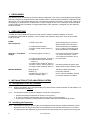
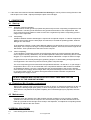
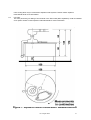
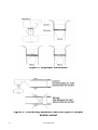
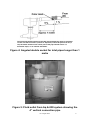
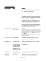
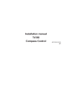
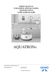
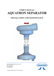
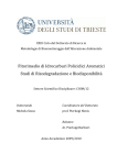
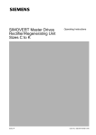
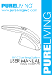
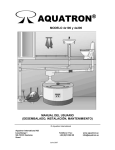
AQUAT RON
®
MODEL 4x300
USER’S MANUAL
(UNPACKING, INSTALLATION, MAINTENANCE)
© Aquatron International AB
Aquatron International AB
Mail address:
Box 2086
SE-194 02 Upplands Väsby
Sweden
Office address:
Lövängsvägen 8
Upplands Väsby
Sweden
1st of August 2002
Phone / Fax:
+468-590 304 50
+468-590 304 94
www.aquatron.se
[email protected]
1. UNPACKNING
The following parts are packed into the Bio Chamber: Separator, hose clip to fix the Separator parts together,
Wire-ring, a branch to be attached to the Bio Chamber outlet, connection pipes between the Separator outlet
o
and branch, 90 Coupler double bend socket connecting the Separator and branch, turning pole, a shovel for
the emptying of compost and a ventilation fan. For pitch changes of the 110 mm inlet pipe, a special angled
coupler double socket is provided. For height adjustments of the separator, a triangular tray with adjusting
knobs is provided.
2. PREPARATIONS
To install the AQUATRON toilet system you will need the following material in addition to the WC.
Components marked with an asterisk (*) are included in the shipment. Other items are to be purchased
locally if needed.
PIPES:
WC to Separator
4" Bend x 90º to WC
4” Coupler double sockets
4” Angled coupler double socket (*)
4” Pipes
Separator – Grey Water
sewage
MISCELLANEOUS
4” Connecting pipes, 2 items (*)
Amount depending on number of
Water Closets to be connected
Amount depending on installation
For 4 % change of inlet pipe pitch
Amount depending on installation
For the fluid outlet of the separator,
- for vertical connection, 75 cm,
- for horizontal connection, 80 cm
For connections
4” Coupler double sockets, 2 items (*)
o
4” Coupler double socket 90 bend,
2 items (*)
o
4” Coupler single socket 90 bend (*)
T-branch 110 mm / 50 mm socket (*)
o
2” Coupler single socket 90 bend (*)
Connecting the Bio Chamber drain
Single socket for Bio Chamber drain
Bark grinds (*)
Platform (*)
Ventilation fan, AC 230 V (*)
100 mm ventilation pipes
100 litres (2 bags at 50 litres)
For the Bio Chamber
For the 100 mm ventilation channel
For the Bio Chamber ventilation
3. INSTALLATION OF THE AQUATRON SYSTEM
3.1 Arrangement of the Bio Chamber
3.1.1
Position the platform firmly and horizontally, then place the Bio Chamber steadily on the platform. For
measurements see Figure 1.
3.1.2
The Aquatron system should be installed in a frost free compartment:
• optimal composting temperature is minimum 12° C (55° F);
• at vermi composting a temperature above 15° C (60° F) is recommended;
• if necessary, insulate the compartment and install a thermostat controlled electric heater.
3.2 Installing the Separator
3.2.1
2
Put together the upper and lower parts of the Separator unless they are already assembled. Check
that the Wire-ring is fully pushed down into the Separator neck and that the wires are not crossed.
The upper part of the Separator (Cyclone) should rest upon the Wire-ring. Tighten the hose clip just
1st of August 2002
as much as needed to keep the upper and lower parts of the Separator together. There must be no
space between the Cyclone and the Wire-ring, see Figure 2.
3.2.2
Place the triangular height adjustment tray on top of the Bio Chamber. Position the separator on top
of the tray and with the separator fluid outlet facing towards the perimeter of the Bio Chamber. Turn
the inlet of the Cyclone towards the pipe coming from the Water Closets. Check that the Cyclone
rests firmly on the Wire-ring and tighten the hose clip.
3.3 Pipe installation
3.3.1
Use 4” pipes between WC and Separator.
NOTE! Only WC should be connected to the inlet of the Aquatron Separator.
Separate pipes should be used for sewage from bath, kitchen, laundry etc. If
these pipes are to be connected, it should be done after the Aquatron system.
3.3.2
The Separator should be connected to a 4” double socket.
NOTE! The Separator must be horizontal and its vertical line (see Figure 2) perpendicular to the Bio
Chamber. The inlet pipe must be fully inserted into the socket, see Figure 3.
3.3.3
The horizontal distance between the WC and the Separator must be minimum 1 metre and that last
metre (closest to Separator) should be pitched at 5% (5 cm), see Figure 4. At further distances the
earlier part of the pipe should have a 1% horizontal slope, or as national standards. If needed, use
the special 4 % angled coupler double socket in order to achieve the pitch transition, see Figure
4.(NOTE! Turn the colour mark of the angled coupler double socket downwards).
Furthermore, check that the inclination of the inlet pipe is smooth and that there are no depressions
where fluid waste may gather.
3.3.4
The ventilation fan should be connected to the 100 mm attachment on top of the Bio Chamber and
further to a separate vent channel. The ventilation fan should be connected to a grounded AC 230 V
electrical outlet.
NOTE! The ventilation must have a separate vent pipe extending over the roof
and must not be connected to the other sewer ventilation of the house, as this
may cause problems with odour and flies.
3.4 Fluid outlet pipe installation
3.4.1
For the pipes between the fluid outlet of the separator and the Grey Water sewage, there are two 4”
connecting pipes included in the delivery. The 75 cm pipe is for the vertical connection and is
connected to the horizontal connection pipe (length 80 cm) by the 90 degree bent double coupler
socket see figure 5. To this connection pipe is also connected the drain outlet from the Bio Chamber
o
(2” diameter) by the 2” Coupler single socket 90 bend and a branch. See figure 6.
3.4.2
The outlet should be firmly attached to the supporting Aquatron 4x300 platform.
3.4.3
One 110 mm diameter Water Seal must be installed before the connection to the regular sewer in
order to prevent odours from the sewer system to enter the toilet/composting system.
3.5 Flushing test
Ask someone to flush the WC with water only and check how much water is entering into the Bio Chamber. If
correctly installed, when flushing with water only, a maximum of 0.5 decilitres should go that way.
If too much water enters into the Bio Chamber there are two explanations
1. If the water enters the Bio Chamber at the beginning of the flushing the velocity of the incoming fluid is
too high and the pitch is too large – adjust (decrease) the pitch of the inlet pipe.
1st of August 2002
3
2. If the water enters the Bio Chamber at the end of the flushing the velocity of the incoming fluid is too low
and the pitch is too small – adjust (increase) the pitch of the inlet pipe.
4. COMPOSTING
4.1 Start up
4.1.1
Drainage of the Bio Chamber:
Spread 25 litres of Bark grinds layer (Note! Not peat moss) into each composting compartment of the
Bio Chamber. The bark grinds should be evenly spread at the bottom of the compartments. Add
some compost from the garden in order to insert micro-organisms. By this the composting process
will get a more rapid start.
4.1.2
Composting:
A balance between Carbon and Nitrogen is required for an optimal compost. In a latrine compost the
Carbon comes mainly from the toilet paper and saw-dust, if inserted as sprinkling powder, while the
Nitrogen is in the faeces.
In the Aquatron systems a good Carbon-Nitrogen balance is achieved when using normal amounts of
toilet paper. If the compost, having a correctly installed Separator, still is wet; the reason might be too
little Carbon. Then sprinkle some saw-dust over the compost.
4.1.3
Vermi composting:
To accelerate the composting process and to effectively reduce the volume (reduction with approx.
90% of original volume), earthworms may be added (Eisenia Foetida, also called Dung Worm or Red
Wiggler; or an equivalent specimen). The worms should be added after a couple of weeks of usage
Compost worms can normally be bought in gardening shops or in stores selling ecological products
and equipments. The worms may also be found in garden compost heaps.
The vermi composting process works best at temperatures between +12 and 25° C. In year usage a
temperature above +15° C is recommended in the compartment where the Bio Chamber is installed.
At temperatures below +10° C the composting process and the activities of the worms is slowing
down and their ‘food supply’ will last longer which may be an advantage in houses which are unused
for a longer period of time. The worms will migrate between the Bio Chamber compartments
depending on the supply of ‘food’.
THE BIO CHAMBER MUST BE INSTALLED IN A FROST FREE AREA FOR THE
SURVIVAL OF THE COMPOST WORMS!
4.2 Emptying a Bio Chamber compartment
Remove the compost using a shovel but leave a layer of approx. 5 centimetres thickness. By this you
will leave the drainage layer (bark grinds), in which a major part of the worms stays, intact. As an
alternative the compartment is emptied completely and a new drainage layer is prepared, see item
4.1.1.
4.3 Maintenance
Regularly check the drainage of the Bio Chamber and the consistency of the compost. If needed
sprinkle some saw-dust over the compost. Also check that the paper in the Bio Chamber does not
build up a pyramid since that might cause a stop in the Separator; if so adjust the composting section
side-ways or switch to the next section.
5. SPECIAL SOLUTIONS
5.1
4
Urine Sorting (Urine diversion):
1st of August 2002
Urine sorting WCs may be connected to Aquatron toilet systems. Please contact Aquatron
International AB for more information.
5.2
UV Units:
UV Units (accessory) for killing of the bacteria in the fluid outlet (after separation) could be installed
as an option. Please contact Aquatron International AB for more information.
Figure 1: Aquatron 4x300 installation measurements
1st of August 2002
5
Figure 2: Separator installation
Figure 3: Connecting Separator and inlet pipe in coupler
double socket
6
1st of August 2002
The horizontal distance between the WC and the Separator must be minimum
1 metre and that last metre (closest to Separator) should be pitched at 5% (5
cm). At further distances the earlier part of the pipe should have a 1%
horizontal slope, or as national standards.
Figure 4: Angeled double socket for inlet pipes longer than 1
metre
Figure 5: Fluid outlet from Aq 4x300 system showing the
4“ vertical connection pipe
1st of August 2002
7
Connection of 50 mm drain from the 4x300 Bio Chamber to the horizontal
pipe from the Aquatron Separator (coming from right) before the connction to
the Water Seal (direction towards left).
Figure 6: Connecting the Bio Chamber drain to the pipe from
the fluid outlet of the Aquatron Separator
8
1st of August 2002
6. ERROR CHECKLIST
TYPE OF ERROR
CAUSE
MEASURE
1. Wet bio-bed
- Bad drainage
Check that the drainage holes are not blocked and that
the drainage layer is according to the manual, see item
4.1.1, Drainage of the Bio Chamber.
- Too much water
in the Bio Chamber
Check that the Separator was installed horizontally and
that its vertical line is perpendicular to the Bio Chamber,
See Figure 2.
Check that the Wire-ring is positioned correctly and that
the wires do not stick to the inside of the the Separator
neck. The wires should be slightly bent towards the
middle of the Separator neck, see Figure 2.
Check that the cyclone is fully pushed down into the
Separator neck and it rests firmly on the Wire-ring.See
item 3.2, Installing the Separator, and Figure 2.
Check pitch of the inlet pipe. At too large pitch, fluid
enters the Bio Chamber at beginning of the flushing; at
too low pitch, fluid enters the Bio Chamber at the end of
the flushing. See item 3.5, Flushing Test.
2. Odour in the room
- Wet bio-bed
See above.
- Wrong ventilation
The ventilation pipe is too short, it does not extend over
the roof. The ventilation is coupled together with the other
sewer ventilation of the house. Backflow? See Installing
the Bio Chamber, item. 3.1.2. NOTE: A vacuum-valve
must not be used.
Check the waterseal to assure that no odour is coming
from the sewer system.
3. Odour when windy
- Air is pressed into
the ventilation
The ventilation pipe does not extend high enough
above the roof. It must be lengthened.
Mount a vane on the ventilation pipe.
4. Stoppage in the
Separator
- A too high pyramid
of paper has been built
up in the Bio Chamber
Turn the active section slightly side-ways or switch to
the next section if needed.
- The wires in the Wirering of the Separator
are bent or crossed
Straighten the wires.
- The inlet of the
Separator is not fully
inserted into the socket
Adjust, see Figure 3.
5. Stoppage in the
fluid outlet of
the Separator
- The flushing water is
entering the Separator
at too high speed
The pipe between WC and Separator has a too
large inclination. See Pipe Installation, items 3.2,
3.3 and 3.5.
6. Flies in the
Bio Chamber
- Wet bio-bed
See item 1 and 2 above; spary the inside of the
Bio Chamber with an appropriate insecticide.
1st of August 2002
9
7. MAINTENANCE/HANDLING INSTRUCTION FOR AQUATRON 4x300
7.1 Drainage of the Bio Chamber
Spread 25 litres of Bark grinds (Note! not peat moss) into each of the Bio Chamber composting
compartments. Add some compost from the garden to insert micro-organisms. By this the composting
process will get a more rapid start.
7.2 Composting
A balance between Carbon and Nitrogen is required for an optimal compost. In a latrine compost the
Carbon comes mainly from the toilet paper and saw-dust, if inserted as sprinkling powder, while the
Nitrogen is in the faeces.
In the Aquatron systems a good balance between Carbon/Nitrogen is achieved when using normal
amounts of toilet paper. If the compost, when having a correctly installed Separator, is still wet; the
reason might be too little Carbon. Then sprinkle some saw-dust over the compost.
When using too much toilet paper there is a risk of building-up a ‘waste pillar’ which may reach up to
the Separator. See item 7.5, Maintenance/Monitoring of the Bio Chamber below.
7.3 Vermi composting
To accelerate the composting process and to effectively reduce the volume (reduction with approx.
90% of original volume), earthworms may be added (Eisenia Foetida, also called Dung Worm or Red
Wiggler; or an equivalent specimen). The worms should be added after a couple of weeks of usage
The vermi composting process works best at temperatures between +12 and 25° C. In year-round
usage a temperature above +15° C is recommended in the compartment where the Bio Chamber is
installed. At temperatures below +10° C the composting process and the activities of the worms is
slowing down and their ‘food supply’ will last longer which may be an advantage in buildings which are
unused for a longer period of time. The worms will migrate between the Bio Chamber compartments
depending on the supply of waste.
THE BIO CHAMBER MUST BE INSTALLED IN A FROST FREE AREA FOR THE
SURVIVAL OF THE COMPOST WORMS!
7.4 Emptying the Bio Chamber
When emptying a section in the Bio Chamber, remove the compost using a shovel but leave a layer of
approx. 5 centimetres thickness. This way you will keep the drainage layer (bark grinds). At extreme
workload conditions or if the composting conditions are unfavorable, further composting might be
needed.
7.5 Maintenance/monitoring of the Bio Chamber
Check regularly the drainage of the Bio Chamber and the consistency of the compost. If needed
sprinkle some saw-dust over the compost. Also check that the paper in the Bio Chamber does not
build up a pyramid which reaches up to the Separator, since that might cause a stop in the Separator;
if so adjust the composting section slightly side-ways or switch to the next section.
10
1st of August 2002