1
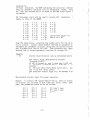
Table of Contents
PAGE
1..
Operator Instructions
Signal Search Simplex Mode
a.
Enhanced Vox Simplex Mode
b.
Half Duplex Mode
c.
Full Duplex Mode
d.
General Description
e.
f. Notice Concerning FCC approval
g. Abbreviated Mobile Commands Chart
1
2
2
3
4
6
8
Installation Considerations
Half Duplex
a.
Full Duplex
b.
Signal Search Simplex
c.
Enhanced Vox Simplex
d.
e. MRTI Grounding and Lightning Protection
9
10
12
13
15
Set-up and Interfacing
a. RIMX Switch Setting
b. RIMX Optional Input
c. RIMX Input/Output
d. RIMX Input/Output Specifications
OTX Switch Settings
e.
16
16
17
17
18
Level Setting
Transmitter Audio Level Setting
a.
Carrier Detect Adjustment
b.
c. Receiver Levels
20
20
21
5.
Installation Checklist
22
6.
System Self-Test
23
7.
Circuit Description/Theory of Operation
RLM-3 Registered Line Module
a.
RIMX Radio Interface Module
b.
OTX System Processor Board
c.
d. MRTI Block Diagram
e. MRTI Interconnect Diagram
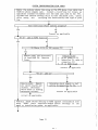
System Trouble Shooting Flow Chart
f.
25
25
26
29
30
31
2.
3.
4.
8.
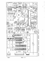
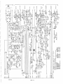
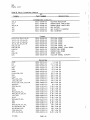
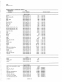
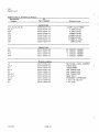
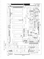
Circuit Drawings
a. RLM-3
Board Layout
Schematic
Parts List
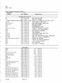
RIMX
b.
Board Layout
Schematic
Parts List
c. OTX
Board Layout
Schematic-’
Parts List
41
41
42
43
44
45
48
49
50
I
9.
PAGE
Table of Contents (continued)
Options (included as applicable)
A. E155AB/TDN6908
Programmable Variables Memory
1.
2.
B.
E375AA/T0N6893
Enhanced Vox Module
1.
2.
3.
4.
5.
C.
B-i
B-i
B-2
B-2
B-3
Installation
Circuit Description
Board Layout (OSVX)
Schematic
Parts List
E376AA/TDN6894A
Full Duplex Module
1.
2.
3.
4.
5.
0.
Variables (parameters) modification procedure---A-i
A-3
Installation
C-i
C-i
C-2
C-2
C-3
Installation
Circuit Description
Board Layout (FDMX)
Schematic
Parts List
E377AA/TDN6895A
Multi-function Utilities
Installation Procedures
1.
2.
3.
4.
5.
6.
7.
8.
9.
10.
ii.
12.
13.
14.
15.
16.
17.
-
Description
and
0-i
Automatic Station Identifier
Security/Executive Override Code Maintenance----D-3
D-3
Multi-digit Mobile access and/or release
Adjustable “signal search” Frequency & duration
D5
times
D-5
Comprehensive Toll Restrictions
D-6
Mobile Signalling Start
Control of External Devices Using the Security
0-6
Code
Land-line Priority with Selective Signalling----D-7
D-8
Variable Length Touch-codes to land line
0-9
Emergency Call Direct Acces
Regeneration
During
Inhibiting Pseudo Touch-Code
0-9
Mobile Dialogue
0-10
Special Mobile Signalling Control
a. High frequency ringing to mobiles
b.
Loud ring to mobiles
c. Multiple ringing to mobiles
0-10
Variable Mobile Inactivity Timer
0-11
Attendant Connect Control
0-11
Land-line Caller Connect Control
D-12
Land-line Message/Hailing Timer
0-13
Variable Overall Access Timer
II
C
G.
PAGE
Table of Contents (continued)
E378AA/TDN6896A Auto Dial I ( 9 number storage) and
E379AA/TDN6897A Auto Dial II (99 number storage)
1.
2.
3.
4.
5.
H.
G-i
G-3
G-5
G-5
G-6
E38OAA/TDN6898A
Selective Signalling of Mobiles (Touch-Code or twotone sequential)
1.
2.
L.
Operator Instructions
Installation
Board Layout (ADLX)
Schematic Diagram
Parts List
Operator Instruction
Installation
H-i
H-i
E38iAA/TDN6899A
Mobile Control of External Functions
1.
2.
3.
4.
5.
Operator Instructions
Installation
Board Layout (ORCTX-i)
Schematic Diagram
Parts List
L-i
L-i
L-5
L-5
L-6
E382AA/TDN6900A
Consolette Sub-fleet Control From Mobile
(Binary Switch Format)
i.
2.
3.
4.
5.
Operator Instructions
Installation
Board Layout (ORCTX-2)
Schematic Diagram
Parts List
L-3
L-3
L-5
L-5
L-6A
E383AA/TDN69OiA
Motrar Sub-fleet Control From Mobile
(i of 4 switch format)
i.
2.
3.
4.
5.
M.
Operator Instruction
Installation
Board Layout (ORCTX-3)
Schematic Diagram
Parts List
L-4
L-4
L-5
L-5
L63
E384AA/TDN69O2A
iA2 Key Telephone System Annunciator
1.
2.
3.
4.
5.
Operator Instruction
Installation
Board Layout (KSAX)
Schematic Diagram
Parts List
III
M-i
M-i
M-2
M-2
M-3
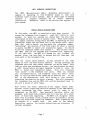
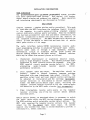
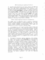
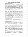
MRTI OPERATOR INSTRUCTIONS
Telephone Interconnect) is
The
MRTI (Microprocessor Radio
different
modes to work with
four
capable of operating in
these
types of systems
Each
of
different types of radio systems.
mobile
operating
different
set
of
slightly
a
requires
section
that
applies
to
Therefore, refer to the
instructions.
your system.
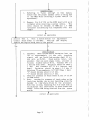
Signal Search Simplex Mode
To
In this mode, the MRTI is installed at your base station.
push the * button on your
access the telephone line (connect),
encoder. In about two seconds you should hear the dial tone,
interrupted by short bursts of squelch noise. These short bursts
are sample intervals during which the MRTI is searching for your
transmitter signal and are heard only by the mobile radio users.
When dial tone is heard, you may enter the telephone number,
“stretching” the duration of the first digit for about a second
to enable the MRTI to detect your transmitter signal. You should
This second * tells
follow the telephone number with another
the MRTI that you are finished with telephone line signalling.
If you omit this, the MRTI will assume you are finished six
seconds after the last digit is entered and will then open the
voice path to the telephone line.
.
When the called party answers, you may converse in the same
manner as with the base station operator. You may interrupt the
telephone party but they cannot interrupt you and be heard. Each
time you push your microphone button, you should pause for about
a half second before you begin speaking in order to allow the
This will eliminate
MRTI to detect your transmitter signal.
When you release
“lost words” to the telephone line party.
your microphone button, the telephone party will hear a short
beep to tell him when he may speak and be heard by you
At the
of the conversation, push the It button on your encoder,
end
stretching the duration for about a second. This will disconnect
the telephone line and the MRTI will confirm discocrnect back to
you with a series of short beeps.
This covers the basic operation of the signal search mode.
Optional control signalling should be handled in the same manner,
always stretching the first control digit in order to be
recognized by the MRTI.
Many hand-held portable radios are
equipped with Touch-Code encoders that will only put out a short
The MRTI will recognize these
burst of Touch-Code signalling.
units with no problem if the transmit button is pressed a second
before the Touch—Code signalling commences. Then, signalling may
Now refer to the General
be entered at a normal rate.
Description section for further instructions and discussion of
optional equipment.
Page 1
(
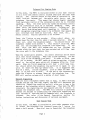
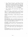
Enhanced Vox Simplex Mode
the MRTI is installed either on your base station
In this mode,
or on a wire-line remote control located away from the radio base
feature unique to this mode of operation is the
The
station.
and the
the mobile radio party,
cross lock-out between you,
This means that whoever begins speaking
telephone line party.
first maintains control of the conversation until he is finished
Then,
the other party may speak and maintain control
speaking.
Then,
the
of the conversation until he is finished speaking.
t?locking out” the
other party may speak and maintain control,
The
first party from being heard until speaking is finished.
MRTI recognizes signalling tones to be different than speech and
for
busy tone, etc.,
will interrupt such tones as dial tone,
Typical operation is as follows:
mobile control.
After a short delay, you
Press the * button on your encoder.
When it
should hear the dial tone for about 2 seconds duration.
You should follow the
enter the telephone number.
drops out,
tells the MRTI
This second
telephone number with another ‘.
If you
that you are finished with telephone line signalling.
the MRTI will assume that you are finished six
omit
this,
seconds after the last digit has been entered and will then open
the voice path to the telephone line.
When the called party answers, you cannot interrupt and be heard
you may
When they finish speaking,
until they finish speaking.
In order to allow time
then talk to the telephone line party.
the MRTI sends an attention-getting ticking
for you to answer,
sound to the called party which will disappear after you first
reply. When you finish speaking he will hear a short beep tone.
You should inform the telephone line party not to speak to you
It is suggested that
until he hears the beep (go-ahead) tone.
such as “when you hear the
concise statement,
this be a short,
At the end of the conversation,
beep it is your turn to talk”.
The
press the II button to release (hang up) the telephone line.
MRTI will confirm release with a series of short beeps.
Network Signalling
or make a dialing
When you dial a telephone number that is busy,
mistake and get the fast busy signal, the MRTI will determine the
repetitive signalling condition and will allow you to hear a few
Then when the MRTI
seconds of the telephone network signalling.
interrupts the signalling you may respond with the II button to
The MRTI will continue to alternate
release the telephone line.
between two seconds of transmitting the repetitive signalling and
five seconds of awaiting mobile commands until the telephone is
Now refer to the General Description section for
released.
further instructions and discussion of optional equipment.
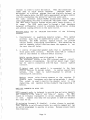
Half Duplex Mode
the MRTI is installed at your radio repeater site.
In this mode,
To access the telephone line (connect),press the * button for
When dial tone is heard,dial the telephone
about a half second.
Page 2
“stretching” the first digit for about a half second in
number,
You
order to allow the MRTI to detect your transmitter signal.
should follow the telephone number with another
This second
tells the MRTI that you are finished with telephone number
If you omit this,
signalling.
the MRTI will assume you are
finished six seconds after the last digit is entered and will
then open the voice path to the telephone line.
.
When the called party answers, you may talk to them in the same
manner as you would to your base station operator or another
mobile except that you will be able to interrupt the telephone
line party but he cannot interrupt you and be heard.
Each time
the MRTI
you finish speaking and release your microphone button,
will send a short beep tone to the telephone party to inform them
that you are finished speaking.
At the end of the telephone conversation, press the II button for
about a half second to release (hang up) the telephone line. The
MRTI will confirm release with a series of short beeps.
Full Duplex Mode
In this mode,the MRTI is installed at your radio repeater site.
outstanding feature of this mode is
The
that
telephone
conversation may be carried on simultaneously in both directions
as with standard home or office telephones.
To access (connect)
the telephone line,
button on your Touch-Code
press the
encoder.
When dial tone is heard,
enter the telephone number.
You should follow the telephone number with another
This
second * tells the MRTI that you are finished with telephone
number signalling.
If you omit this, the MRTI will assume you
are finished six seconds after the last digit is entered and then
open the voice path to the telephone line.
.
When the telephone line party answers,
you may converse in the
usual manner. At the end of the conversation, press the # button
to release (hang up) the telephone line.
The MRTI will confirm
release with a series of short beeps.
Now refer to the General
Description section for further instructions and discussion of
optional equipment.
Page 3
(
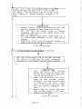
GENERAL DESCRIPTION
(Common to all modes of operation)
The
previous
sections have covered the
mobile-originated
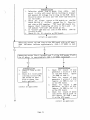
telephone call. The telephone caller originated call proceeds in
two different manners, depending on installed options.
If
special information (security code,selective signalling code,
trunking format, etc.) is required to initiate mobile signalling,
refer to the applicable option section in this manual for
operational details.
Special Instructions Apply
Yes
No
Refer to Section (s)
When the telephone caller dials the MRTI telephone number, the
MRTI detects ringing on its line (as indicated by flashing
decimal point of display on OTX processor board). After ensuring
that the channel is available (carrier detect and PTT sense LED
must be off, located on RIMX board
or absence of receive audio
Indicated in test 5 by an
(or noise) in audio vox mode.
extinguished decimal point of display on OTX processor board),
the MRTI transmits
one three-second ring tone.
To answer
the call, the mobile operator presses * on his encoder after the
ring tone ceases.
The MRTI will access the telephone line and
conversation may proceed as outlined in the previous sections.
When the conversation is over, the mobile operator sends a II to
release the telephone line. The MRTI will confirm release with a
series of short beep tones.
This completes instructions on the
basic MRTI telephone call originated from a land telephone.
The MRTI has a number of standard convenience features including:
1.
Re-dial of the last telephone number dialed.
2.
“Flash”
(**).
signal.
(Applicable on certain PBX equipment).
This allows the mobile user to regain in-house dial
tone without releasing and reaccessing the patch.
(call
transfer, etc.).
(*11*).
3.
Answer if called. (*11* before access). Will access the
telephone line only if an incoming call is waiting.
(Special
application).
4.
The end of telephone number signalling time is announced by a
short beep after which the voice path is enabled to/from the
telephone line.
5.
The MRTI can share a telephone line with a standard telephone
set.
This can eliminate the need for a separate telephone
line dedicated to the MRTI.
6.
MRTI telephone line busy signal. When a mobile user attempts
to access the MRTI telephone line and the line is off-hook
(in use by a line-sharing telephone set, etc.), the MRTI will
Page 4
The line may be
return a busy signal to the mobile user.
accessed in this condition by the busy override code. (***).
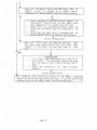
There are many standard switch-selectable features including:
7.
Ring signalling to mobiles initiated after first or fourth
ring fourth ring feature allows an attendant to answer calls
on a line sharing telephone set (as discussed in 5 above)
before the mobiles are alerted.
8.
An attendant can
Yes or No.
Attendant control of MRTI:
initiate or forward calls to the mobile users via a touchline-sharing telephone set by dialing the
code equipped,
(#*).
attendant access code.
9.
MRTI
Yes or No.
Toll (long distance) restriction:
the
digit
of
the
first
entered
as
disconnects when 1 or 0 is
telephone number.
10.
Transmitter private line signal disable: On command only or
In either case, the
choose one.
automatic on access
This feature allows use of
on/off commands are functional.
the MRTI without disturbing other mobile users in the
In the latter condition, the private line signal
system.
may be commanded back on in order to involve another mobile
user in the telephone conversation.
-
Tx PL tone on
Tx PL tone off
=
(
*111
=
Yes or No.
11.
Call origination from mobile users:
12.
Call origination from telephone line:
13.
Three-minute overall access timer:
14.
Emergency override of three-minute access timer: Yes or No.
Override code = *** (or security code, if applicable, refer
to Section D).
15.
Access elapsed time coded tones:
1 minute
2 minutes
=
=
On or Of f.
On or Of f.
one short beep.
two short beeps.
Also, if the three-minute timer is on:
2-3/4 minutes
release.
16.
=
Yes or No.
(as in
13).
one tick every 2 seconds until
3
minute
Yes or No.
Release after 60 seconds of mobile inactivity:
If mobile activity timer is on, “ticks are sent 15 seconds
Reception of a mobile signal will
prior to disconnect.
reset the mobile inactivity disconnect timer.
Page 5
Associated with the standard features are Touch-Code command
These
signals utilizing the , It, and 1 buttons on your encoder.
outlined
in
the
the
manner
in
be
entered
should
digit
the
first
“stretching”
MRTI Operator Instruction Section,
Some examples follows:
where applicable.
*11*
*1*
* 111
11*
Access telephone line.
Redial last number dialed.
Overrides line busy.
override 3 minute overall timer.
After access:
called
answer
(special
if
access:
Before
application).
“flash” as applicable.
After access:
Transmitter PL tone on.
Transmitter PL tone off.
By attendant, Touch-Code telephone allows attendant to
initiate ring signalling to mobile user(s).
NOTICE
equipment contains one or more
This IAI telephone interconnect
IAI Model RLM-3 telephone interface circuit cards which have been
approved by the Federal Communications Commission for connection
to the public-switched telephone network under part 68 of the FCC
rules and regulations.
The following information is supplied to ensure user
with the regulations.
compliance
1.
The Model RLM-3 telephone interface circuit card may not
used with party lines or coin lines.
2.
protective
or
connecting terminal equipment
Customers
before
such
shall,
network
circuitry to the telephone
telephone
of
notice
company
to the
give
connection is made,
made,
is
to
be
the particular lines to which such connection
FCC
the
and
shall provide to the telephone company
registration number and ringer equivalence of the registered
terminal equipment or registered protective circuitry.
3.
The customer shall give notice to the telephone company upon
final disconnection of such equipment or circuitry from the
particular lines.
4.
the customer
When telephone line trouble is experienced,
shall disconnect the registered equipment from the telephone
is
equipment
registered
if the
to
determine
line
is
if
and
the registered equipment
malfunctioning,
be
shall
the
use of such equipment
malfunctioning,
discontinued until the problem is corrected.
5.
The telephone company may make changes in its communications
operations or procedures, where such
facilities, equipment,
Page 6
be
action is reasonably required in the operation of its
business
and is not inconsistent with FCC rules
and
regulations.
If such changes can be reasonably expected to
render any customer’s terminal equipment incompatible with
telephone company communications facilities,
or require
modification or alteration of such terminal equipment,
or
otherwise materially affect its use or performance,
the
customer shall be given adequate notice, in writing, to allow
the
customer an opportunity to maintain
uninterrupted
service.
6.
It is required by FCC regulations that repair of the Model
RLM-3 shall be accomplished only by the manufacturer or by
their authorized agent.
7.
All Models RLM—3 shipped in equipment bearing the appropriate
FCC registration label are equipped with plugs that mate with
USOC
the
type RJ11C interface connectors supplied by
telephone company.
8.
The FCC registration number for the IAI Model RLM-3 interface
circuit card is BC288J-68921-VP-N.
The ringer equivalance is
O.3b.
(
WARNING
This equipment generates, uses,and can radiate radio frequency
energy and if not installed and used in accordance with the
instruction
manual,
may
cause
interference
to
radio
communications.
It has been tested and found to comply with the
limits for a Class A computing device pursuant to Subpart J of
Part 15 of FCC Rules which are designed to provide reasonable
protection
against such interference when operated
in
a
commercial environment.
Operation of this equipment in a
residential area is likely to cause interference in which case
the user at his own expense will be required to take whatever
measure may be required to correct the interference.
Page 7
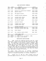
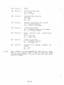
ABBREVIATED MOBILE COMMAND CHART
Note:
All multidigit control functions must be entered with
maximum of 1 second interdigit time.
a
STANDARD MRTI
*
access telephone line
release telephone line
#
**
redial last number called
overrides line busy
= 3 minute timer disable
after access
*11* before access = answer if called (special applications)
(momentary on-hook to regain dial
= “flash”
after access
tone where applicable)
#*
attendant access code
*1* TX PL tone on
*111 TX PL tone off
E381/TDN6899 Mobile Control of External Functions Option
*N* function on where N is one of 7 functions N = 3-9
*N# function off
E377/TDN6895 MULTI-FUNCTION UTILITIES OPTION
n*
mu]tidigit access code N = 1-4 digits
multidigit release code N = 1-4 digits
#N
*O#N executive override code N = 1-6 digits
overrides a variety of programmed restrictions
E378/T1JN6896 OPTION CONTROL (9 NUMBER AUTO-DIAL I)
*1 MRTI dials stored telephone number 1
*9 MRTI dials stored telephone number 9
E379/TDN 6897 OPTION CONTROL (99 NUMBER AUTO-DIAL II)
*01 MRTI dials stored telephone number 01
*99
MRTI dials stored telephone number 99
AUTO DIAL TELEPHONE NUMBER ENTRY FROM MOBILE
(MRTI must not be accessed)
*0* auto-dial programming command followed by:
L* telephone number memory location (1 = 1 or 2 digits as
followed by:
applicable)
to be stored (N = 1-16 digits) at memory
number
N. .N telephone
(*
entered
as a telephone number digit causes
location L
followed by:
auto-dialing)
1.25 second pause in
*ji
number to be stored
telephone
causes
command:
memory store
at memory location L
II reset to start over (anywhere in the sequence)
-
.
-
E380/TDN6898 SELECTIVE MOBILE SIGNALLING OPTION
*ll#N revertive (mobile-to-mobile) call where N is mobile
code in 1, 2, 3, or 4 digit-format.
Page 8
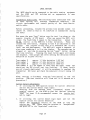
paging
INSTALLATION CONSIDERATIONS
MODE DISCUSSION
The MICROPROCESSOR RADIO TELEPHONE INTERCONNECT system provides
Half duplex, full duplex,
four basic operational mode options.
Basic operation
signal search simplex and enhanced vox simplex.
and interfacing requirements are discussed as follows:
HALF DUPLEX
simplex mobiles and/or portables). This mode
(Duplex repeater
is used when the MRTI interfaces the telephone line(s) directly
to the repeater in a radio system utilizing standard simplex
control station(s), mobiles and/or portables. When the telephone
line has been accessed for land line and mobile conversation, the
repeater transmitter is keyed continuously for the duration of
The MRTI automatically adjusts the
the telephone conversation.
levels in both the mobile to land-line and land-line to mobile
audio paths within a 15 db range.
-
The radio interface module (RIMX) incorporates receive audio
input programming switches to establish “ballpark” input levels.
Receive audio input is through a high impedance, balanced
differential circuit to eliminate hum and noise pickup and
Repeater receiver
adverse loading affects on the audio source.
audio may be taken from several places as follows:
1.
(Preferred) discriminator or quadrature detector output,
This method provides audio
prior to high frequency rolloff.
Also, the
unaffected by level controls within the repeater.
RIMX squelch circuit provides carrier detect to the MRTI,
circuit
squelch
receiver
model-to-model
eliminating
performance variations.
2.
The amplifier should be
Local speaker audio amp output.
loaded to prevent frequency response problems
properly
The
associated with some transformer type output circuits.
amplifier output level and local squelch control setting must
be adjusted at installation and the settings maintained.
Carrier detection in this method is switch selected for
either the RIMX carrier detect logic input, utilizing the
repeater receiver squelch circuits or for the receive-audio
vox detection by the MRTI audio circuits (not recommended).
3.
Other intermediate
receiver utilizing
described above.
receive audio source on the repeater
one of the two carrier detect methods
Mobile carrier detect, as mentioned above, is necessary to switch
the audio paths within the MRTI during telephone conversation.
The
The RIMX provides switch selectable carrier detect options.
MRTI also examines the repeater receive private line decoder
On carrier
output via the P.L. Detect logic level input.
squelch only systems this input is switch-disabled to provide a
continuous P.L. detect condition.
Page 9
This PTT signal keys
MRTI PTT output connects to “repeater PTT”.
the repeater transmitter without disabling the repeater receiver
audio circuits.
MRTI transmit audio output is also balanced to provide hum and
noise immunity and connects to the repeater exciter audio input.
The output is virtually transparent to circuit impedances of 600
ohms or less allowing connection or disconnection of the MRTI
without affecting normal repeater audio levels.
disable) a relay closure is
P.L. Stripping,
(transmit P.L.
This feature is on/off-controllable by a mobile
provided.
command and may be switch-programmed to operate on access.
Release always resets this function.
Monitor,
prior to
is used
monitor
mobiles).
a relay closure is provided to disable receiver P.L.
ring signalling in applications where receive audio vox
to detect mobile activity (as discussed previously,
to
also operates during standard ring signalling
Auxiliary receiver logic level and audio vox input also provided
for use in systems requiring a separate monitor receiver to
monitor the channel prior to ring or selective signalling.
FULL DUPLEX
Operation in
(Duplex repeater, duplex mobiles and/or portables).
This mode
this mode requires the FDMX module (E376/TDN6894).
d-line
obile
mobile-to-lan
and
features simultaneous land-line-to-m
accessed
for
been
has
telephone
line
.
When the
conversation
keyed
is
,
repeater
transmitter
the
conversation
telephone
The
continuously for the duration of the telephone conversation.
automatically
circuits
MRTI audio measurement and gain control
standardize the mobile-to-land-line audio path, while the FDMX
module audio circuits maintain a uniform average land-line-toThe FDMX also features an electronic hybrid
mobile audio path.
circuit which maintains a high quality audio path.
The radio interface module (RIMX) incorporates receiver audio
input programming switches to establish “ballpark” input levels.
The MRTI auto-level circuits further adjust audio levels within a
The RIMX audio input is through a high impedance,
15 db range.
balanced differential circuit to eliminate hum and noise pick up
Repeater
and adverse loading effects on the audio source.
receive audio may be taken from several places as follows:
1.
(preferred) discriminator or quadrature detector output,
This method provides audio
prior to high frequency rolloff.
Moreover,
unaffected by level controls within the repeater.
the RIMX squelch circuit can be utilized, simplifying overall
installation.
Page 10
2.
The amplifier should be
Local speaker audio amp output.
properly
loaded to prevent frequency response problems
The
associated with some transformer-type output circuits.
amplifier output level and local squelch control setting must
be adjusted at installation and the settings maintained.
Carrier detection in this method is switch selected for the
RIMX carrier detect logic input, utilizing the repeater
receiver squelch circuits or for the receive-audio vox
detection by the MRTI audio circuits (not recommended).
3.
Other intermediate
receiver utilizing
described above.
receive audio source on the repeater
one of the two carrier detect methods
Mobile carrier detect,
as mentioned above,
is necessary for
function
control
and for mobile timer reset and control
recognition.
The RIMX provides switch selectable carrier detect
options.
The MRTI also examines the repeater receiver private
line decoder output via the PL detect logic level output.
PL Detect logic level input.
On carrier squelch only systems
this input is switch-disabled to provide a continuous PL detect
condition.
MRTI PTT output connects to “repeater PTT”.
This PTT signal keys
the repeater transmitter without disabling the repeater receiver
audio circuits.
MRTI Transmit Audio output is also balanced to provide hum and
noise immunity and connects to the repeater exciter audio input.
The output is virtually transparent to circuit impedances of 600
ohms or less allowing connection or disconnection of the MRTI
without affecting normal repeater audio levels.
PL Stripping,
(transmit PL disable) a relay closure is provided.
This feature is on/off-controllable by a mobile command and may
be switch-programmed to operate on access.
Release always resets
this function.
Monitor,
to ring
used to
monitor
mobiles).
a relay closure is provided to disable receiver PL prior
signalling in applications where receiver audio VOX is
detect mobile activity.
(as discussed previously,
also operates during standard ring signalling
to
Auxiliary Receiver logic level and audio VOX is provided for use
in systems requiring a separate monitor receiver to monitor the
channel prior to access, ring, or selective signalling.
Page 11
SIGNAL SEARCH SIMPLEX
(Simplex base station, Simplex mobiles)
This mode is used when the MRTI interfaces the telephone line to
a standard Simplex base station.
When the telephone line is
accessed for land-line and mobile conversation, the base station
is keyed and taken down for short mobile-carrier sampling
intervals, typically 20 milliseconds in duration every half
second. Optional programming can select sample durations from 15
to
100 milliseconds at a sample rate of one every
250
milliseconds to one every 2.5 seconds. When mobile carrier
is
detected the transmitter is held down for an additional 350
milliseconds for receiver PL detection.
If the PL signal is
detected, the transmitter is held down until the loss of either
carrier detect or FL detect.
Upon loss of a valid mobile
carrier, the transmitter again begins its previous sampling.
The radio interface module (RIMX) incorporates receive audio
input programming switches to establish “ballpark” input levels.
The MRTI audio measurement and gain control circuits further
“auto level” the mobile to land-line and land-line to mobile
audio paths within a 15 db range. Receive audio input is through
a high impedance, balanced differential circuit to eliminate hum
and noise pickup and adverse loading effects on the audio source.
Receive audio is obtained as follows:
1.
Discriminator or quadrature detector output, prior to high
frequency rolloff. This method provides audio unaffected by
audio level controls.
Moreover, the RIMX squelch circuit
provides carrier detect, eliminating model-to-model receiver
squelch circuit performance variations.
2.
Other receive audio interface configurations are possible
utilizing the base station squelch circuits for carrier
detection but are not recommended.
Base station transmit-to-receive recovery time must be less
than 15 milliseconds for this mode, as is the case in most
recent equipment.
Optional programming (as
previously
discussed) is available for station equipment not meeting
this requirement.
FL Detect logic level input connects to the receiver private
line decoder output.
On carrier squelch systems this input
is
switch-disabled to provide a continuous PL
detect
condition.
MRTI PTT to one of the following:
1.
On private line squelch base stations
(Preferred) Mike PTT.
this
requires the disabling of reverse burst timing while
the MRTI is operating the transmitter.
The MONITOR relay
closure is operated (closed) during access in this mode of
Page 12
The monitor
operation in order to facilitate this function.
relay contacts connect to a point which disables the PTT
delayed-off function and yet allows the private line encoder
to operate.
2.
A PTT point on the base station transmitter that does not
In some
activate the delayed-off (reverse burst) function.
the point designated DELAYED PTT satisfies this
cases
condition.
The MRTI PTT sense function, used to detect “station busy,”
“station ID required”, is incorporated into the PTT output.
Therefore, the station PTT source chosen should operate when
the transmitter is keyed from base mikes, desk sets or other
sources.
Transmit audio output is also balanced to provide hum and noise
1
immunity and connects to the base station “mike high and mike b’
The MRTI output is virtually transparent to circuit
inputs.
impedances of 600 ohms or less. Jumpers that keep the base
microphone or desk set handsets “hot” should be cut.
PL stripping,(transmit p1 disable) a relay closure is provided.
This feature is on/off-controllable by a mobile command and may
be switch-programmed to operate on access. Release always resets
this function.
The Monitor relay is
Reverse burst disable relay closure.
operated during access and provides a relay closure for disabling
Also, operates
the delayed PTT function on P.L. stations.
during standard ring signalling.
ENHANCED VOX SIMPLEX
(Simplex base station, Simplex mobiles/portables) used in high
interference environments where signal search simplex is not
feasible or in applications where mobile carrier is not directly
i.e., repeater control stations or remote control
available,
in this mode requires the E375/TDN6893
Operation
points.
This mode features negative response time
Option.
Enhanced VOX
VOX operation on, land-line audio utilizing digitally delayed
This eliminates “lost words” from the
audio.
transmit
telephone party while maintaining apparent instant VOX response
that
also are audio processing circuits
Featured
time.
automatically adjust the VOX circuits thresholds for background
noise and detects the presence of land-line signalling such as
dial tone, busy tone, etc.
Initially,
The mode of operation is standard cross-lockout VOX.
land-line,
the
from
or
mobiles
the
from
with no audio detected
in
station
the
with
base
condition
the MRTI is in the idle
out
lock
will
direction
either
VOX detected audio from
receive.
the other direction. Receive audio from the mobile maintains the
Land-line speech maintains the transmit
receive condition.
condition. Land-line signalling is allowed to proceed for a few
Page 13
(
Then the transmitter is
seconds in order to alert the mobile.
Landline audio
is
taken down to allow mobile response.
maintained at a uniform average level and digitally delayed on
the OSVX module while the MRTI audio measurement and gain control
circuits standardize the mobile-to-land-line audio path.
The radio interface module (RIMX) incorporates receive audio
input programming switches to establish “ballpark” input levels.
The MRTI audio circuits further adjust audio levels within a 15
The RIMX audio input is through a high impedance
db range.
balanced differential circuit to eliminate hum and noise pickup
and adverse loading effects on the audio source.
Receiver Audio
sources:
may
be
obtained from either
of
the
following
1.
This method
Discriminator or quadrature detector output.
provides audio that is unaffected by audio level controls.
Moreover,
the RIMX internal squelch circuit can provide
carrier detect, simplifying installation. This method may be
set
used on repeater control stations where the repeater is
for zero turn-off delay.
2.
A source of squelched speaker audio that is unaffected by
Receiver audio VOX is normally
front panel level controls.
used in this method to indicate mobile act.ivity.
Mobile carrier detect used with method 1, above.
The preferred source is the RIMX internal squelch circuit.
the carrier detect logic input
Under special circumstances,
station squelch
may be used in conjunction with the base
circuits.
is connected to the base
PL detect used with method 1,
station receiver PL decoder output.
In carrier squelch only
a
systems,
input is switch-disabled to provide
this
continuous PL indication.
Monitor output relay closure connects to the receiver PL
disable input (necessary only when using methods 2 above).
This output is used to monitor the channel prior to ring
signalling,
and operates during standard ring signalling to
mobiles.
MRTI PTT CONNECTS TO MIKE
PTT.
MRTI transmit audio is balanced to provide hum and noise immunity
The MRTI
’ and “mike b’
t
t inputs.
and connects to the “mike hi
output is virtually transparent to circuit impedances of 600 ohms
or less.
Jumpers that keep the microphone or desk-set handsets
hot” must be cut.
PL stripping (transmit PL disable).
A relay closure is provided.
This feature is on/off-controllable by a mobile command and may
be switch-programmed to operate on ac:cess. Release always resets
this function.
Page 14
MRTI Grounding and Lightning Protection
To provide ground reference for the logic inputs to the MRTI and
to enable the extensive lightning and surge protection in the
MRTI,
the MRTI must be ground bonded to the associated radio
or larger,by connection
equipment through the supplied #12 wire,
to the bolt marked EARTH GROUND on the MRTI rear panel and to the
The connection to the radio frame should
radio equipment frame.
be to bright metal that is a part of the radio proper such as an
internal side rail, the connection marked GROUND on the newer
series of base stations or by removing one of the antenna
connector screws and using a lug of the correct size on products
This grounding should be extended to the
such as MAXAR, MOXIE.
ground utilized by the telephone company’s surge protector
installed on the phone line(s) used by the MRTI.
General System Lightning Protection Considerations
The damage done by lightning is due to potential differences
developed between equipments, between equipment and the power
between equipment and the outside telephone line and
source,
Two things are
finally between equipment and, earth ground.
damage.
imperative if we are to minimize lightning
All equipment at a site should be bonded frame-to-frame with
1.
This common ground should be bonded
adequately sized conductor.
to the utility entrance ground cable and the telephone entrance
Bear in
if different from the utility entrance ground.
ground,
like
not
mind that lightning is essentially r.f. and as such does
this
as it “sees”
long leads and will not tolerate sharp bends,
If a tower is used it is essential that the
as a high impedance.
At a site
common ground system also be bonded to the tower.
where these various components are encountered (tower, utility
telephone ground) it is suggested that #6 bare copper be
ground,
used as a minimum.
The degree of insurance against lightning, after bonding,
2.
is almost directly related to the RESISTANCE of the earth ground
All grounds connected in parallel contribute to
(s) used.
lowering the net ground resistance (tower, utility, telephone, if
For “hot” sites (sites where lightning is known to
independent).
regularly cause damage) it is well to use multiple ground rods
spaced several feet apart and bonded together with #6 or better
wire.
If soil is sandy or rocky the local utility company can
usually provide excellent advice if their engineering office is
contacted relative to the local methods used to obtain a low
engineering
ground.
Many times these utility
resistance
departments will measure your site effective ground resistance
with their specialized equipment, if approached in the right way.
Remember the potential of lightning is what does the damage and
the lower the lightning
the lower the ground resistance,
potential.
Page 15
(
Set-up and Interfacing
RIMX (RADIO INTERFACE MODULE)
Switch Settings
All of the MRTI inputs and outputs connected to the radio station
The base receiver-related
equipment are located on the RIMX.
switch programmable to
circuits
are
logic
input
audio and
The
requirements.
accommodate the various operating mode
following is a description of switch functions.
on for private line systems
off for carrier squelch systems
SW1
FL Detect
SW2
carrier detect select:
on for external squelch circuit
off for internal squelch circuit
SW3
carrier detect logic
direction (SW2 on)
on for carrier
off for carrier
SW4
enable
=
=
on for FL detect
PL
detect input
logic direction (SW1 on) o.ff for PL detect
toward ground
toward + supply
=
=
toward ground
toward + supply
SW5
RX audio lvl select:
below)
(see
on selects low level input
off selects high level input
SW6
RX audio de-emphasis
select:
(see below)
on selects no de-emphasis
off selects 6db/octave de-emphasis
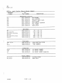
Receiver audio level requirements
Receive Audio Source
high level disc./detector
low level disc./detector
high level speaker audio
low level speaker audio
SW5
off
on
off
on
SW6
off
off
on
on
level from receiver:
(1000hz tone deviated 4khz)
5db (.45 vac)
approx.
approx. -20db (.08 vac)
approx. +10db (2.5 vac)
5db (.45 vac)
approx.
-
-
Examples of low level detector audio are MAXAR 80 and FLEXAR base
High level discriminator/detector audio
station receivers.
from MICOR base/repeater, ri DISC INPUT or MITREK base, buffered
detector audio.
-
OPTIONAL INPUTS
Auxiliary Receiver Audio
This input is not level-programmable and requires a nominal input
level of 0db (.78 vac).
Alternate for
Auxiliary Receiver Carrier Indicator Logic input.
above. Used in applications requiring monitor receivers.
Logic low = carrier.
Patch Inhibit Logic input.
land-line signalling.
A logic-low
Page 16
disables
mobile
and
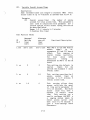
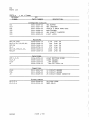
RIMX INPUT/OUTPUT INTERFACE
p12
pin 1
pin 2
color
brn
red
function
TX PL disable (stripping)
TX PL disable return
I or 0
relay output
relay output
pin 3
pin 4
org
yel
monitor (or reverse burst disable)
monitor return
relay output
relay output
pin 5
gm
PTT ground (return)
relay output
pin 6
blu
receiver carrier indicator
logic input
pin 7
pin 8
vio
gry
receiver audio return
receiver audio high
linear input
linear input
pin 9
wht
PTT (and PTT sense)
relay output
pin 10 blk
receive PL detect
logic input
pin 11 tan
pin 12 pnk
transmit audio return
transmit audio high
linear output
linear output
P11
pin 1
pin 2
brn
red
optional functions
auxiliary receiver audio low
auxiliary receiver audio high
linear input
linear input
pin 3
org
patch inhibit
logic input
pin 4
yel
aux. receiver carrier detect
logic input
p13
pin 1 black
pin 2 red/bik
pin 3 black
power supply input
d.c. negative(-)
d.c. positive (+), 10.5-16v/a.c. input
a.c. input, 18 vac nominal
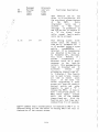
INPUT/OUTPUT SPECIFICATIONS
RIMX contains the lightning protected logic and linear
The
input/output signal circuits and the power supply for the MRTI.
the exception of the receiver carrier indicator logic
With
input, all logic level inputs are protected 5-volt CMOS Schmitt
l level of 3.5 volts
t
trigger type and will accept input logic Hhi
The carrier
and a maximum logic “lo” level of 1.5 volts.
indicator logic input has an adjustable switching threshold with
a range of +.03 volts to +11.7 volts with a maximum hysteresis of
0.5 volts at the 6-volt threshold level. This input also accepts
logic high levels in excess of 100 volts.
differential
balanced
inputs are
in
linear
audio
The
configuration to minimize cross-talk and hum. The transmit audio
output is in balanced transformer, dc isolated configuration.
outputs are 0.5 amp dry relay closures which are
The
protected against burn-out by 10 ohm or 2.7 ohm fusing resistors.
Page 17
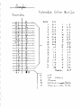
OTX SWITCH SETTINGS
Additional system programming is accomplished by 16 switches
the OTX processor board as follows:
SWITCH
Section 1
SW1
-
SW1
SW1
-
-
on
Auxiliary receiver channel monitor mode:
on = audio VOX (receive audio)
of f = logic level input
Section 2
Channel monitor source:
on = main receiver
off = aux. receiver
Section 3
Main receiver carrier indicator source
= RIMX squelch/logic level input
on
off = audio VOX (receive audio)
receive
when in the off position,
Note:
audio is used as the source for carrier
indication i.e.
(the MRTI detects that the
mobile is transmitting by the presence of
RIMX/logic level (SW1-3 ON)
receive audio).
is recommended in all cases even when the
Enhanced VOX Option is installed, unless it
is not possible to obtain an input from the
receiver discriminator or a logic level input
from the squelch detector in the receiver,as
in installations directly to a remote control
is
receiver
the actual
where
console
inaccessible.
SW1
SW1
SW1
-
-
-
Section 4
Toll restriction
restrict
on
off = no restriction
Section 5
Signalling to switched network
= Touch-Code
on
off = rotary
Section 6
Mobile call origination
=yes
on
off = no
(refer to Page G-3, Parameter 96)
SW1
SW1
-
-
Section 7
Switched network (land-to-mobile)
call origination
=yes
on
no
off
Section 8
Duplex/simplex select
full duplex
= half duplex,
on
off = simplex
Page 18
SW2
SW2
SW2
SW2
SW2
SW2
SW2
SW2
-
-
-
-
-
-
-
-
Section 1
Option
Section 2
Access time coded tones
= tones
on
off = no tones
Section 3
60-second mobile inactivity
disconnect
on
=yes
off =no
Section 4
Emergency three-minute timer override
on
= can be overridden
off = cannot be overridden
Section 5
3-minute access timer:
on
= automatic release after 3 minutes
off = no 3-minute release
Section 6
Mobile signalling
calls)
on
= first ring
off = fourth ring
Section 7
Transmit PL stripping
= automatic on access
on
off = on command only
Section 8
Attendant (line
control
=yes
on
off = no
start.
sharing)
(land-to-mobile
telephone
set
Upon completion of switch programming,
press the red t1
reset”
button.
This causes the MRTI to ?Iread?? the switches and change
the program appropriately. This must be done every time a switch
setting is changed.
Page 19
LEVEL SETTING
The MRTI should now be connected to the radio station equipment
and the RIMX and OTX switches set as appropriate to user
specifications.
Transmitter Audio Level The following tests associated with the
TX level setting will indicate transmitter modulator
IDC
circuit performance and overall quality of the land-line-tomobile audio.
-
Before proceeding, disable the private line encoder output (or
remove PL reed) so that no PL code/tone is transmitted during
the tests.
Now press the gray “test” button once for test 1 as shown on the
numeric display of OTX board.
After one second the MRTI will
output the Touch-Code II signal to the transmitter.
Adjust the
TX LVL control on the RIMX for 3.0 khz deviation.
Press and
release the test button, stepping to test 8 as indicated on the
display.
The purpose of this test is to determine IDC circuit
The MRTI will output a sequence of
level set and performance.
nine tones numbering 0 to 8 on the display.
The sequence may be
stopped at any tone by pressing the red “reset” button during
that tone interval.
Pressing the reset button again will resume
the sequence. With proper IDC level setting the deviation levels
should be as follows (w/o PL).
Tone number 0
approx. 1.3 khz deviation ( 697 hz)
Tone number 7
approx. 2.5 khz deviation (1633 hz)
Tone number 8
approx. 4.5 khz deviation (2000 hz)
Tone number 8 is 5 db higher in level than the other tones and
should put the IDC circuit just into limiting.
If these levels
are not closely duplicated, it will be necessary to readjust the
transmitter IDC level and check the modulator circuit tuning (if
any).
After testing is finished, step the “test button” to the off
position.
(The test condition will “time out” in 15 minutes as a
precaution.)
Carrier Detect Adjustments
1. If utilizing the RIMX squelch circuit forcarrier detection
and not the carrier detect logic input:
Starting from the maximum level (clockwise) adjust the
squelch control on the RIMX so that the desired quieting
level (at least 10 db recommended) causes the carrier det.
LED to light.
2.
If utilizing the carrier detect logic input
squelch circuit for carrier detection:
Adjust the threshold control on the RIMX
carrier det. LED lights when the receiver is
and goes off in the “squelched” condition.
Page 20
and
not
the
so that the
“unsquelched”
Receiver Levels
1. If utilizing the discriminator/detector output:
No level setting necessary apart from RIMX switch settings.
2.
(
If utilizing speaker audio source:
Adjust the internal volume control (where applicable, such as
wire-line remote consoles) for a level of +10 db (2.5 vac) or
alternately -5 db (0.45 vac) (see RIMX Set-up and Interfacing
section) with a 1000 hz tone, deviated 4 khz into the
receiver.
Level setting complete.
(
Page 21
INSTALLATION CHECKLIST
1.
Connect MRTI to radio station.
2.
Check for proper grounding and lightning protection.
3.
Set switches on RIMX board.
(refer to RIMX Switch Settings)
4.
Set switches on OTX board.
(refer to OTX Switch Settings)
5.
Installation level checklist
set TX deviation to
Punch up test 1.
a.
3 khz (no FL tone)
6.
Insure 4.5
khz deviation.
b.
Punch up test 8-tone 8.
c.
Carrier detect/squelch adjustment.
d.
Receiver Audio:
Discriminator/detector source; no level
Check setting of SW5
setting necessary.
and SW6 on RIMX.
set volume control
Speaker audio source;
for +10db (2.5 vac) or -5db (0.45 vac)
while receiving 1000 hz @ 4 khz deviation
(SW5 and SW6 on RIMX set accordingly).
Enter option parameter data where applicable
(refer to Options section of this manual).
Page 22
SYSTEM SELF-TESTS
The self-contained tests are invoked and controlled by the test
and reset buttons on the OTX processor board.
Each time the
test button is depressed,the next test is selected.
The test
number is displayed for 1 second upon entry into test before the
test is started.
This allows entry into any test without
activating other tests.
Each time the test or reset buttons are
depressed, the test timer is reset.
If and when the test timer
reaches 15 minutes,
the MRTI will revert to the normal idle
condition, ready to handle communications.
1.
Level Set/Check to Transmitter and Switched Network.
Touch
code “II” is generated and sent to the transmitter and
switched network amplifiers at the reference level.
The
transmitter is keyed and the SN is accessed.
This test is
used to adjust and/or check the level to. the associated
transmitter.
The transmitter is adjusted to +-3 kc deviation
If the switched network line is 600
(in a 5 kc system).
ohms,
the level to the SN will be -10 dbm +- 1.5db.
The
decimal point on the LED display indicates the state of the
patch inhibit input, lighting when at logic low.
2.
Transmitter and SN Linearity/Touch-Code Decoder Test.
This
test effectively tests most of the linear circuits in the
MRTI.
The transmitter is keyed, the sn is accessed and TX PL
disable is activated.
The tone generators generate touch?I*H,
code “1” to “0”,
and “It” at 8 levels from -18 db to +5
db,
3 db steps (with respect to reference in test 1).
The
tones are sent to the phone line and the transmitter.
The
Touch-Code decoder is fed from the phone line (effectively)
and its output displayed on the LED display.
The display
decimal point displays “data valid”.
Therefore, with the
phone line unterminated, the display should show all 8 levels
of all tones except ““ and “It” which cannot be displayed
(although the decimal point will indicate “data valid”).
The
reset button will slow the test.
The second reset
will
freeze the test, and the next reset will resume the test.
3.
Receiver to SN Test.
This test may be used to test mobile
Touch-Code encoders, distortion, etc.
The SN is accessed and
the monitor function is activated.
The audio path from the
receiver through the variable gain stage, to the switched
network is established.
The Touch-Code decoder is fed from
the receiver,
and its output displayed on the LED display.
When the decimal point is on, Touch-Code data valid is
indicated. The audio path is autoleveled by the processor to
test the firmware.
4.
Switched Network to Transmitter Test.
This test tests SN
autoleveling.
The transmitter is keyed, the SN accessed and
the audio path from the sn through the variable gain stage to
the transmitter is established.
The Touch-Code decoder is
driven from the sn and displayed on the display.
SN VOX
(processor determined) is indicated by the decimal point.
Page 23
5.
Tests audio paths from the
Receiver to SN Signalling Test.
The sn is
receiver to the SN and Touch-Code decoder.
accessed and the audio path from the receiver, through the
variable gain stage, to the sn is enabled (when not receiving
The Touch-Code decoder is
telephone number signalling).
The
driven from the receiver and displayed on the display.
decimal point is on when RX VOX (processor determine) is
detected.
6.
Tests the audio and logic inputs
Auxiliary Receiver Tests.
from an auxiliary receiver. The sn is accessed, the audio
path is established from the auxiliary receiver through the
The
variable gain stage to the sn (Multiline L1158A only).
decimal point indicates auxiliary receiver logic low input if
SW1, Section 1 is off or auxiliary receiver VOX if SW1,
Section 1 is on. Also tests contacts of switches 1 and 2 of
With all switches on, A “1” should be
the OTX board.
Afterward, each switch may be exercised to test
displayed.
for proper operation, observing that the displayed “1”
extinguishes only when an individual switch is turned
completely off.
7.
Tests the MRTI ability
Non-accessed Switched Network Test.
to monitor activity on its telephone line when not accessed.
The transmitter is keyed and the audio path is established
from the non-accessed telephone line through the variable
gain stage to the transmitter when “off hook” is detected by
The
The decimal point “on” indicates off hook.
the MRTI.
Touch-Code decoder is driven from the non-accessed SN and
Ringing on the non-accessed SN is
displayed on the display.
indicated by the flashing of the decimal point.
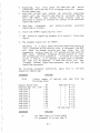
8.
Single tones are
Single Tones to the Transmitter and SN.
sent to the transmitter and switched network at 0 db (with
respect to reference in test 1) except for tone #8 (+5 db).
The sn is accessed and the transmitter keyed; each tone is .5
Reset freezes the test and a second reset resumes
seconds.
The tone number is displayed on the display. The
the test.
decimal point on indicates PL/DPL logic input or carrier
indicate.
0
1
2
3
4
5
6
7
8
9.
=
=
=
=
=
=
=
=
=
697
770
852
942
1209
1336
1477
1633
2000 at +5 db
This test position is used to modify parameters in the
optional NVRAM. Refer to the section “Parameter Modification
Section A, for
Procedure” in the Option E155/TDN6908,
details.
Page 24
CIRCUIT DESCRIPTION
/
THEORY of OPERATION
RLM-3 Registered Line Module
The RLM-3 interfaces the public switched telephone network to the
MRTI control module. It is registered with the FCC under part 68
It provides a very high degree of
of the FCC regulations.
isolation from lightning type impulse voltages on the telephone
lines when properly installed and grounded in the radio system as
The
detailed in this manual under “lightning protection.”
limiting
RLM-3 also provided the time averaged signal power
limiting
out-of-band
signal
circuitry
as
well
as the
chracteristics required by FCC regulation for registration under
the most demanding device category regulation (“VP”).
The LIM-1 module on the RLM-3 monitors dc and ac voltages on the
telephone line, converting them to levels and signals usable by
the OTX control module.
Pin 4 of the RLM-3 outputs switched
network audio (accessed or not accessed) at the same level as
seen on the telephone line.
Additionally, the dc level is logic
high when the PSTN voltage is below approximately 17 volts and
logic low when the PSTN voltage is above approximately 17 volts.
This indicates to the OTX control module when the line is in use
by another party (or defective).
Pin 3 of the RLM-3 outputs
voltage
logic high when the
on the PSTN exceeds approximately 65
volts and logic low below 65 volts.
The OTX module uses this
information to detect ringing on the PSTN(after checking the
period of several transitions to insure the signal being received
is ring and not dial pulses).
The OTX module accesses and pulse dials the telephone line
applicable) by putting logic low on pin 5 of the RLM-3.
(if
RIMX Radio Interface Module
The RIMX interfaces the radio system (remote, microwave channel,
Additionally, the input power
etc.) to the OTX control module.
is converted to the voltages required by the system. A very high
degree of immunity to lightning type impulses is achieved in the
design. and layout of the RIMX.
Power for the MRTI is supplied through a transformer that is
plugged into a receptacle external to the MRTI. This transformer
inherently provides a large amount of protection from impulses
and surges. Also powered by external D.C. thru P11, pin 1 and 2.
A.C. input 18v nominal. D.C. 1O.5-16v.
Additional thyristor protection is provided on the RIMX and is
very effective when the MRTI is installed and grounded in the
radio
system as detailed in this manual under “Lightning
Protection.
IC1 is the constant frequency, pulse-width controlled switching
D21 provides
regulator control element for the 5-volt supply.
the
switching
mode
for
the
system.
1C2
is
failure
protection
regulator for the -6 supply.
Page 25
and logic
Logic outputs to the radio are through relay closures,
inputs from external sources are through high impedance (200k)
Audio output to the radio transmitter is through an
inputs.
isolation transformer, driven by a variable gain amplifier stage.
Audio inputs from the receiver and optionally an auxiliary
balanced,
channel monitor receiver, are via high impedance,
differential inputs.
PL detect input from radio (if applicable) can be set to respond
or disabled for carrier squelch
to positive or negative inputs,
applications.
or audio VOX
a logic level input is required for receiver carrier
If
switches can select either polarity, and a threshold
indication,
control adjusted to respond to small or asymmetrical swing
Indicator LEDs are included to monitor input and output
signals.
and
installation
simplifying
considerably
states,
logic
subsequent trouble shooting.
sources
audio
for high level/low level
compensates
SW5
flat
selects
SW6
and
etc.)
(discriminator, quadrature detector,
rolloff
6
db/octave
or
output
circuits)
response (from audio
(taken from radio detector). The internal squelch control is set
for 10-20 db of quieting, when used.
OTX System Processor Board
The OTX control board can be broken down into functional
as follows:
blocks
1.
Digitally controlled audio gain stage consisting of ICs 36,
The processor can select the gain stage input
35, 34 and 33.
via 1C36 and route the gain stage output to various locations
Processor control of 1C34 controls the gain of the
via 1C33.
and 1C35B comprise a high pass
1C35A ,
function block.
1C35 converts the CMOS
p1, etc.
filter to eliminate hum,
ladder network in 1C35 to a variable gain function.
2.
Tone Generator 1 and 2
The programmable timer module (PTM) IC11 produces square
waves at the required frequency under firmware control.
These square waves are converted to triangle waves by
Ground reference is guaranteed by
transconductance amp 1C22.
Peak value is
and 1C25.
1C24,
of
and
E
inverters F
peak value
This
1C26D.
and
C49
1C25A,
1C24D,
determined by
output at
digital
The
1C27.
comparator
is applied to step
wave by
sine
step
20
a
to
converted
the step comparator is
controlled
Processor
network.
associated resistor
the
Low pass
IC3OD and 1C29C.
amplitude is provided by IC3OC,
and 1C31
wave
sine
the
in
filter 1C29C removes the steps
Tone
circuits.
various
to
distributes the resultant output
off
rolls
filter
pass
low
generator 2 is the same except its
frequency.
at a higher (-3db at 2500 hz)
Page 26
3.
4.
Peak Reading Voltmeter Circuit
Processor controlled input to the voltmeter is via 1C38.
Range select is controlled by 1C39 and amplifier 1C42C. This
signal is rectified by the precision rectifier circuit of
1C42D and 1C42A.
This dc level is compared with the voltage
generated by counter 1C40 and associated 1R-2R resistor
network, in comparator 1C42B. The comparator output controls
clock generator 1C43C.
The processor selects an input, sets
the range,
and resets the counter.
When an ac signal is
detected, the counter counts up to the peak value of the
signal.
The processor will then read the counter output and
respond as required.
Switches Network Amplifiers
IC41A mixes the various signal sources in a summing amplifier
configuration.
This summed signal drives the switched
network line through driver IC4C.
Signals from the switched
network are amplified by IC4B and distributed as necessary.
IC41D amplifies the signal from the nonaccessed switch
network, and IC21E detects the associated logic level.
5.
Transmitter Summing Amplifier
Signals from the various sources are
IC41D and sent to the RIMX.
summed
in
amplifier
6.
Touch-Code Decoder
Touch-code decoder 1C20 is time shared on the various inputs.
The processor selects an input for the decoder via 1C37 and
reads the results.
7.
Mic. non-buss related circuits
A. Display decoder
1C18 decodes and drives the LED display in
processor commands.
8.
response
to
B.
Programming Switches
Switch
bank SW1 is continuously available to
the
processor
for
reading while switch bank
SW2
is
multiplexed with display information and tone generator
amplitude signals. Therefore, to read SW2, the processor
reconfigures the associated lines as inputs,
reads the
switches, and restores the line as outputs.
C.
Reset and test switches.
These switches cause interrupts to the processor and the
processor responds as required.
System reset is not
generated by the reset button.
System Reset Circuitry
Power up (C6 being discharged) causes processor IC1O to be
initially reset.
Upon charging,
IF
the reset is removed.
the unregulated supply on the RIMX drops below 15 volts,
(power fail),
1C43A and 1C43D cause NNI (non-maskable
interrupt) to occur first, causing the processor to go into a
Page 27
)
non-volatile RAM protection routine.
Then system reset is
exerted.
When the system is operating normally, interrupts
are generated every 5 milliseconds on the IRQ line (short,
negative
pulses every 5 milliseconds).
It has
been
established
that anything that upsets normal processor
operation (such as inadvertently shorting data lines, induced
pulses from external sources, etc.) will cause the IRQ pulses
to change drastically in frequency.
IC3C and associated
parts keep reset from occurring as long as IRQ pulses are
present.
When lost, the system will automatically reset and
attempt restarts until successful.
9.
Processor Bus Related Functions
A. Chip select decoder
1C2 decodes the addresses generated by the processor and
enables the appropriate ROM, RAM, PIA or PTM.
B.
NVRAM (optional)
IC1
provides 256 four-bit bytes
nonvolatile random access memory.
of
shadow
-
type
C.
Processor
IC1O is the microprocessor which controls the MRTI
System.
The 3.58 mhz clock signal is derived from the
Touch-Code decoder 1C20 which is crystal controlled.
D.
Parallel Interface Adaptors
PIAs, 1C12, 13, 14, 15 and optionally 16, 17 are 20-line
devices which can be programmed by the processor such
that each line can be an input readable by the processor
or a latched output.
Most of the inputs and outputs of
the processor are through these PIAs.
E.
Programmable timer module
IC11 is a three-section timer module that times the 5
millisecond interrupts, and generates the square waves
for tone generators 1 and 2.
F.
Read Only Memories
)
The MRTI processor program is contained in read only memory
(ROMs) and is field replaceable (socketed) as necessary.
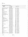
Basic firmware is contained in one or more ROMs so marked,
and optional firmware, (autodial, multi-function utilities
or selective signalling) is contained in other ROM(s) also
designated.
A 2-letter designation indicates the supplied
firmware as follows:
BSC
UT
AD
SS
-
-
-
-
Basic MRTI firmware,
functions
Multifunction Utilities
Autodial 1
Selective Signalling
Page 28
required
-
-
-
for
all
Option E377/TDN6895
Option E378/TDN6896
Option E380/TDN6893
MRTI
0
-u
RIUX
RLM
PIAI—PA6
I
ING
HES
4MM
L
DER LAY
H
IAI
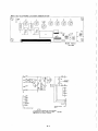
010995
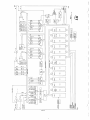
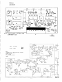
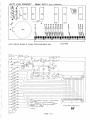
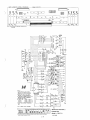
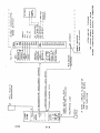
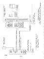
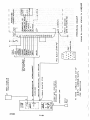
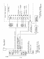
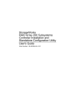
MRTI
BLOCK DIAGRAM
P11
I
I
I
I
2
LJJI3
El
P13
LIGHTNING
PROTECTION
RLM
IN
1>MRI
I
‘WALL
I
IPLUGI
JI2 OUTSIDE PINS ARE
KEYED(PLUGGED)J12 I
PIN NO.:p12 PIN NO.
PLUS I
12
P12
J12
I
LIGHTNING
PROTECTION
RIMX
J6
P6
CABLETOAUXILLARY CABLE TO RADIO
RECEIVERANOPATCH
INHIBIT(WHEN REQUIRED)
I
I
I
I
Jil OUTSIDE PINS
ARE KEYED(PLUGGED
JII PIN NO.=PII PIN NO.
PLUS I
o
0
II
I
P1
JI
I
I
I
j
OTX
BOARD
P2
1
1J21
I
NOTE
ADLX
HW
8685
CABLES SLIDE OUT OF
CHASSIS SLOTS FOR
SERVICING
33
J3 37 KEY PIN
IS BLOCKED
J9 12 KEY PIN
IS BLOCKED
JI OUTSIDE PINS AREKEVED (PLUGGED)
JI PIN NO.: P1 PIN NO. PLUS I
FDMX/OSVX
BOARD
I
f
P8
J8
I
CABLE TO
OPTIONS
I
I
USOC
Ei RJIIC MALE
TELEPHONE LINE
I
[
F
P7J
JACK
P9 TO OPTIONCABLE
OR CIRCUIT BOARD
TEST/MONITOR
IN TERCONNEC T DIA GRA M
J6 OUTSIDE PINS ARE KEYED OEARTH GROUND
TERMINAL POST
(PLUGGED) J6PIN NO.: P6PIN
NO.PLUSI
,I2
MR TI
SYSTEM TROUBLESHOOTING-FLOW CHART
Remove the modular phone line plug on the OTX phone line cable from
the RJ11c phone company jack.
Connect a touch-tone (or rotary, as
applicable) standard telephone into the same jack used by the MRTI.
originate and receive several calls to test the phone line, central
office setup, etc.
verifying the functionality and type of phone
line.
(a
I
Does Substitute Phone operate properly?
Yes
No
Correct as applicable
1
EE
“PS ok’
t
I
LED on RIMX board on?
Yes
No
I
I
I
Is there 12 to 24 VDC across C9?
Yes
No
Remove power and disconnect
J6 from RIMX P6. Restore
LPower.
1.
2.
3.
Possibilities
No AC power to T3
Defective T3, cable or
connector J13
Fl on RIMX Blown
correct as applicable
I
“PS ok”
LED on?
I
Remove power. Remove
all option boards and
recheck. Determine
which board is drawing
excessive, current.
Determine which supply is def
ective by measuring +5, B+, -6.
correct as applicable
correct as applicable
I
I
Carefully check switch setting on RIMX against installation notes
and/or “RIMX” radio interface module switch settings in this
[janual or installation guide, as applicable.
I
Page 31
I
Are RIMX switches correct?
Yes
correct and retest
Activate test 1 (refer to HDescription of TestsH Section 6 of
this manual for details).
I
Does the MRTI respond to test and
reset buttons?
r
Yes
1.
2.
3.
4.
5.
Processor not running
possibilities
Carefully check that program ROM(s) and address prom
are present, inserted in their sockets properly, and
are of the same software series (number and letter
marked on ROMs).
Check that processor 1010 is properly inserted and
seated in its socket.
Check that DTMF decoder 1C20 is properly inserted
and seated in its socket (1C20 generates the clock
signal for IC1O).
Check for presence of clock signal (895 KHZ) at pin
39 of 1010 with X10 lo cap probe of oscilloscope.
Check for presence of 5 millisec interrupt pulses at
R49 test loop with X10 lo cap probe of oscilloscope.
correct as applicable
Does test 1 lite the PTT and PTT sense LEDs?
Yes
No
1.
possibilities
RIMX to OTX cable defective, not seated, etc.
check for logic low at Pin 13, 1C7 on the RIMX
board.
If low, and PTT LED not on, check IC 7
LED,
etc.
If logic hi,
suspect OTX board,
Connector, etc.
correct as applicable
)
Page 32
q________________________________
E rD0es
I
Test 1 key the transmitter?
No
1.
2.
3.
possibilities
is properly
Check that J12 (radio cable connector)
connected to P12 on the RIMX.
Check connection of white (PTT) and green (PTT return)
wires to radio PTT circuits.
With the white (PTT) wire temporarily disconnected
from the radio, measure the resistance between the
white and green wires in the MRTI radio cable (should
be less than 15 ohms)
correct as applicable
C
Does test 1 deviate the transmitter approximately 3 khz?
No
Yes
1.
2.
3.
possibilities
is properly
Check that J12 (radio cable connector)
connected to P12 on the RIMX board.
Check connection of pink (transmit audio hi) and tan
(transmit audio low) wires to radio mike circuit.
Measure between the pink and tan wires with an AC
meter.
Normally, about .165 vac will deviate the
transmitter about 3 khz.
(this value is for incircuit measurements.
Since the MRTI transmit audio
circuits are normally bridged across the radio mike
circuit,
open circuit measurements will be much
higher). This level can be adjusted with the ??TX LVLI?
pot R503 on the RIMX board.
correct as applicable
TDoes the voltage across tip and ring of the telephone line on
the RLM board drop from about 48 volts to less than 17 volts
when test 1 is activated as indicated by the t
off hook” LED on
the RLM board coming on?
Yes
No
Page 33
1.
2.
3.
4.
possibilities
Reset
Defective phone line or phone line cable.
in
display)
(nothing
button
patch to idle with reset
and measure DC voltage tip to ring on the RLM board.
Should be about 48 volts and “off hook” LED should be
out (on hook).
Check for proper inputs to LIM module on the RLM
Short tip
ground Pin 1).
board (B+ Pin 4, +5-Pin3,
“Off hook LED should lite.
and ring on RLM together.
Remove short (restoring 48 volts to Pin A and B of
LIM module) “off hook” LED should go out.
check Q4
If “access” LED does not lite on OTX board,
circuit on OTX.
Check Q2, Qi, Ki circuits on RLM board.
correct as applicable
Measuring across tip and ring on the RLM board with an AC meter,
does the meter indicate approximately -10db (.25 VRMS) in test
1?
F
No
Yes
Measuring across Pins 6 (ground) and 7 of the RLM header P7 with
the AC meter, is approximately -8db (.31 VRMS) indicated?
No
Yes
1
1
1.
2.
possibilities
Check Fl fuse on RLM
board.
Check IC 2 voice power
limiting circuit (VR1
LED turned on hard
with no phone line
Audio applied).
1.
2.
3.
correct as applicable
4.
possibilities
Check for output of tone
generator 1 at pin 3 of 1C31
(approx
on the OTX board.
.44 VRNS in test 1).
Check for output of tone
generator 2 at pin 3 of 1C32
(approx .44 VRMS in test 1)
on the OTX board.
for output of SNS
Check
Amplifier at Pin 1 of 1C41
(approx .56 VRNS in test 1)
on the OTX board.
Check for output of phone
line driver and at pin 8 of
1C4 (approx .56 VRMS in test
1) on the OTX board.
correct as applicable
I
Page 34
Remove the modular plug from the phone company jack. Start
Test 2.
The LED display should show the numbers 1 thru 0
and 2 blank segments (*and# not displayable) in sequence.
This test exercises most of the linear circuits on the OTX,
RIMX and RLM boards (refer to “System Self-Tests” section
of
this
manual for details).
Monitor the
radio
transmitter for presence of the test 2 tones. Monitor the
telephone line for presence of the tones.
I
I
Is test 2 normal?
r
Yes
I
I
Reconnect Modular v1u
correct as applicable
Determine the source of receiver audio in this system.
(Normally,
speaker
audio in trunked control
station
applications and remote console interface applications only.
Most other installations use audio (and detect carrier) from
the radio discriminator/detector).
1
Does this system use discriminator/detector audio as
source?
I
audio
I
Yes
No
I
Go to Soeaker Audio Procedure”
Does the “carrier det” LED on the RIMX lite
receiver is receiving a 20db quieted signal.
Yes
when
the
No
11
Normally, squelch is detected by the squelch circuits
internally on the RIMX board.
Is squelch detected
internally in this system?
Yes
I
No
Referring
to
RIMX schematic
and
RIMX
input/output specifications, troubleshoot as
applicable.
Page 35
I
1.
Measure across the gray (RX audio hi) and: violet (RX
audio lo) wires from the radio cable where they are
attached to the radio with a high impedance
AC
voltmeter or oscilloscope.
With no RJ signal into
the receiver (measuring squelch noise),
the meter
should read about .45 VAC (high level discriminator
output) or about 80 millivolts AC (low level detector
output).
Check the RIMX switch settings to ensure
proper settings for this installation (refer to the
“RIMX radio interface module switch settings” in this
manual).
2.
With a 10db quieted signal injected into the
receiver,
set the control T502 on the RIMX to just
illuminate the “carrier det” LED (refer to “Level
Setting” in this manual).
Check 1C5,
1C6,
1C4,
1C8,
1C9 circuits for proper
operation.
3.
correct as applicable
With radio receiving a system mobile, is the “PL det”
(in non-PL systems,
FL LED is on all the
LED on?
time).
)
N
1.
2.
3.
possibilities
Check setting of RIMX switches.
Ensure system ground between MRTI and radio is in
place.
Measure where the black (RX PL detect) wire from the
radio cable is connected to the radio with a DC
voltmeter or oscilloscope (PL systems only).
When
PL is being received,
the opposite logic level
should be seen from that of not receiving PL (logic
thresholds
greater than 3.5v = high, less than 1.5
volts = lo).
-
correct as applicable
Speaker Audio Procedure
Activate Test 3.
Transmit Touch Codes from a system
mobile (or equivalent). Does the LED display show the
decoded digits from the mobile,
and the display
decimal point indicate digit valid when receiving
modulation from the mobile?
Also, advance to Test 5,
does display decimal point indicate RX VOX when
receiving modulation from the mobile?
I
Yes
o
Page 36
1.
2.
possibilities
Referring to “Level setting” in this manual,
ensure that the proper speaker level is being sent
to the MRTI while receiving a system mobile (or
equivalent).
Measure Pin 8 of 1C6 on the RIMX board with an AC
This
voltmeter while receiving a system mobile.
level should be between .45 VRMS and 1.4 VRMS
(processor autoleveling will compensate over this
range).
correct as applicable
T Activate
transmit
With a system mobile (or equivalent)
Test 3.
Does the LED display
Touch Codes to the MRTI.
mobile?
indicate the digits being sent by the
No
Yes
1
1.
2.
3.
possibilities
Carefully check system mobile deviation (set max
overdrive
IDC to approximately 4.8 khz with
and set Touch Code encoder digit #5 to 3
signal,
Check mobile twist, with
khz with no PL/DPL.
encoders that can send single tones, proceed as
disable mobile TX FL. Transmit 697 (1 &
follows:
Deviation should be about ±
2 buttons both down).
Now transmit 1477 (3 & 6 buttons both
1 khz.
Deviation should be about ± 2.2 khz (6
down).
db/octave TX pre-emphasis, 1477/697 times 1 khz).
11 should deviate about ± 3.5 khz.
j
1t
tilfi should deviate about + 2.7 khz.
Check for presence of Touch Codes at Pin 14 of 1C4
on RIMX board.
testing for presence of touch codes on the
Note:
touch-tone decoder can be very deceiving since the
decoder is time-share driven by the processor.
With this in mind, examining Pin 9 of 1C20 with an
oscilloscope will show bursts of Touch Codes with
steady Touch Code being received from the system
mobile.
correct as applicable
Page 37
Activate test 4. If the E375/TDN6893A Enhanced VOX Module,
or
E376/TDN6894A, Full Duplex Module, is in place, test 4
will route the telephone audio through the module audio
or
If
E375/TDN6893A
the transmitter.
to
circuits
test 4 will route the
E376/TDN6894A is not present,
telephone line audio through the variable gain stage to the
Using a Touch-Code telephone (or other Touchtransmitter.
impress Touch Codes on the telephone line.
Code source),
Note:
The LED indicator will show the decoded digits.
sustained, high level tones (greater than -10 DB) on the
phone line will cause the voice power limiting circuit on
the RLM board to open the audio path to the MRTI until the
Voice or momentary bursts (such as Touch
audio is removed.
Does tI
Codes) will not cause this switching to occur.
LED display show the decoded digits?
)
No
Yes
1.
2.
possibilities
Measure between pins 6 (ground) and 7 of the RLM header
P7 with an AC voltmeter while tones or audio are on the
phone line.
Measure between “linear ground” loop on OTX board and
Pin 7 of IC4 with the AC voltmeter while tones or audio
on the phone line.
correct as necessary
r
Is the audio on the telephone line being transmitted to
the system mobile (or equivalent) at a normal, compressed
or autoleveled amplitude (delayed about .5 seconds if
option 2 is present)?
No
Yes
1.
2.
3.
4.
ps sib i lit ies
Check pin 2 of P1 on the OTX board for presence of the
telephone audio.
or
VOX
module)
(enhanced
If
E375/TDN6893A
E376/TDN6894A (full duplex module) is present, check
for output of module audio at Pin 7 pf P1 on the OTX
board.
If E375/TDN6893A or E376TDN6894A is present, check for
logic lo at Pin 1 of P1 on the OTX board (SNB on).
If E375/TDN6893A is present, check for logic lo at pin
VOX).
2 of P2 on the OTX board (sample
If E375/TDN6893A and E376/TDN6894A are not present,
check for telephone_line audio at Pin 7 of 1C4.
-
5.
correct as applicable
Page 38
Activate test 7. Dial the telephone number of the MRTI
from another phone and phone line to allow the MRTI to
see ringing.
Does the decimal point on the LED flash
during ringing to indicate processor recognition of
ring?
Yes
1.
2.
3.
4.
possibilities
Measure between tip and ring connectors on the RLM
board for presence of ring voltage (60-100 VAC).
The
“off hook” LED normally glows at
reduced
brightness (duty cycle of ring signal) during ring.
Check “off hook” LED.
With high impedance scope probe, check header Pin 3
for square waves exceeding 2.6 volts peak during
ringing.
Scope Pin 2 of 1C21 on the OTX board for presence of
square waves during land-line ringing.
correct as applicable
F
I
No
Is this system a trunked system?
4)
I
Yes
Does the “carrier detect” LED on the RIMX light when
the station is keyed from the local microphone?
( indication of “mic enable” from the radio processor)
Yes
1.
2.
3.
possibilities
setting of
Check
switches
RIMX
against the installation instructions
for the radio being used (especially
“carrier det direction”, etc.
Check with DC voltmeter the point
where the blue (receiver
carrier
indicator) wire from the radio cable
is connected to the radio.
Cause
audio to be received and verify that
the logic level is changing at this
point.
Ensure that the ground connection
from the MRTI cabinet to the radio
Frame is securely made.
correct as applicable
Page 39
•
Does the “PL detect” LED on the RIMX light when the
“patch”
button
is pressed on a system
mobile?
(indication of “patch enable” from the radio processor)
\
Yes
No
1.
Check settings of the RIMX switches against the
installation instructions for the radio being
used (especially “P.L. detect direction” etc.
Check with a DC voltmeter the point where the
black wire (PL detect input) is connected to the
radio.
Verify that the logic level is changing when the
mobile “patch” button is operated and released.
2.
3.
correct as applicable
Does the “TX PL strip” LED light and the point
the brown wire (patch status) from the radio
connects to the radio,
go from logic high to
low?
(
where
cable
logic
r
)Yes
No
1.
)
2.
possibilities
Go to Test 2 and check operation of the TX PL
strip relay.
The resistance between the brown
and red wires in Test 2 should be less than 15
ohms.
Check the interface to the radio processor
system.
correct as applicable
r
This completes basic functional testing of the MRTI.
Carefully
compare the switch settings of Switch 1 and 2 on the OTX board with
the definitions in this manual under “OTX Switch Settings”.
Page 40
Other Possibilities
1.
2.
3.
4.
If your unable to resolve the problem by following the
then refer to the System Self -Tests”
preceding flow chart,
Every input and output can be tested
section of this manual.
using these procedures.
Ensure that the orange “inhibit” lead is not accidentally
grounded, inhibiting the MRTI (see test 1).
Ensure that the ground lead from the MRTI to the radio is in
place and electrically sound.
To ensure that option programming (multi-digit access, multi
selective signalling, etc.) is not causing
digit release,
disconnect power and remove
seemingly defective performance,
all option ROM(s),(labeled with one or more of the following
2-letter designation; UT, AD, SS.) leaving only basic ROM(s)
BSC.)
(Labeled with the following 3-letter designation;
If correct performance is obtained, reinstall ROMs
Retest.
(parameter)
and check NVRAM programming (see “variables
and other
modification procedure” under E155/TDN6908A
applicable option sections.
Page 40-A
NOTE CIRCUIT BOARD IS SHOWN FROM
COMPONENT SIDE
103163
RLM—3
IAI
VRI
AUDIO
HI
TIP
AUDIO
LO
ACCESS
PWR SPL
RETU RN
NOTES
I. Arrows up go to B+
2. Arrows down go to reference.
3. Copocitors ore in mlcroforads,
resistors ore in ohms, Unless noted
4
+9—15V IN
OFF HOfr<
4.
0
Indicotes
screw terminol.
RING
DETECT
PT
PAGE 41
IAI
PARTS LIST
RLM—3 LINE INTERFACE MODULE
REFERENCE
IAI
SYMBOL
PART NUMBER
IC1
1C2
Zi
INTERGRATED CIRCUITS
3301—10055—00
3301—10006—00
3301—10044—00
DESCRIPTION
QUAD OPERATIONAL AMPLIFIER
QUAD FET INPUT OPERATIONAL AMPLIFIER
PROGRAMMABLE ZENER DIODE
D4,D5
D2,D3
D6
Dl
D7
Di ODES
3302—20008—00
3302—20003—00
3302—20005—00
3302—20001—00
3302—20014—00
SILICON DIODE
4.7 VOLT ZENER DIODE
18 VOLT ZENER DIODE
SILICON DIODE
ZENER
R35
Ru
R12
R21
R9
R7
R3,25
R26,R27
R20,33
R22,R23
RB
Ri
R34
R13
R2,4,5,6,15,16
R17,18,28,29,30,36
R14
R31
R1O,R24
R19
R32
RES I STORS
3303—03300—10
3303—06800—10
3303—01001—10
3303—01201—10
3303—01801—10
3303—02201—10
3303—03301—10
3303—06801—10
3303—01002—10
3303—01202—10
3303—01502—10
3303—02202—10
3303—03902—10
3303—04702—10
3303—01003—10
3303—01003—10
3303—01203—10
3303—04703—10
3303—01004—10
3304—04992—10
3303—02701—10
330
680
1K
1.2K
1.8K
2.2K
3.3K
6.8K
10K
12K
15K
22K
39K
47K
lOOK
lOOK
120K
470K
1MEG
49.9K
2.7K
Cl ,C2
C3,C4
C5,C9,C1O
C7
C8
Cli
LED 1
C6
CAPACITORS
3306—35900—00
3306—11030—00
3306—01003—00
3306—44704—00
3306—41004—00
3306—02700—00
3306—00750—00
3306—41505—00
073184
PAGE—42
1/4W
1/4W
1/4W
1/4W
1/4W
1/4W
1/4W
1/4W
1/4W
1/4W
1/4W
1/4W
1/4W
1/4W
1/4W
1/4W
1/4W
1/4W
1/4W
1/4W
1/4W
5%
5%
5%
5%
5%
5%
5%
5%
5%
5%
5%
5%
5%
5%
5%
5%
5%
5%
5%
1%
5%
.1MFD TUBULAR
.O1MFD DISC
.1MFD CERAMIC
4.7MFD/20 VDC TANTALUM
1MFD/35 VDC TANTALUM
270 PF CERAMIC
LED
15MFD/20V TANTALUM
(
C
IAI
PARTS LIST
RLM—3 LINE INTERFACE MODULE
REFERENCE
IAI
SYMBOL
PART NUMBER
DESCRIPTION
L1,L2,L4
L3
COILS
3307—00010—30
3307—10000—00
1.2MH CHOKE (DC RESISTENCE 15)
CHOKE ASSEMBLY (DC RESISTENCE APPROX 5)
Q1,Q4,Q5
Q2,03
ThANSI STORS
3309—44010—00
3309—44030—00
NPN
PNP
LIM1
S1,S2
VR1
Fl
F2
RiOl
Ti
Ki
P7
MI SCELLANEOUS
3312—10000—00
3312—20000—10
3312—42000—00
3312—10125—00
3312—12500—00
3305—05001—00
3308—03873—00
3310—00008—00
3311—10007—20
LINE INTERFACE MODULE
TRANSIENT SUPPRESSOR
OPTO—ISOLATOR
1/8 A FUSE
1/4 A FUSE
5K POT
AUDIO COUPLING TRANSFORMER
RELAY
7 POS -‘EADER
021684
PAGE —42A
TRANSISTOR
TRANSISTOR
w
m
G)
>
-o
(J)
CD
-a
-
-
R9
Ru
R13
8
R33
1
C2
R31
R17
RIS
R21
D8
R49
R43
-
Fl
4215
F
I
S21
SI
I
I
I
—ie—
D2
R76
°_
R7j3
w
w
033
--
C2 3
...RIOO
0IR
R
C22 97
R94
C2 I
:°_fl_
)T
1
R
R98 TEST
R96
—CR93
.—0R92
—0R91
(
÷
-L
34
D04
R109 RIIO
I
120
D25 R79
024
023
R82I
CI9
-1I•-
CI8 -fl-- L
R
89 -*C 29
R
8
TORe
R8l0I
83
c,
1
C26
027* I I
CI7*
R85
R
Rj4? 0186
D26,*,I
I
R
IC I
-v
O—---0RI08
D22 RIO7
C 25
1341 T -41C36
RQj.. -H-
T
0
E
C35 -II
RI35
R 504
PS
1C2
I
C40 RI42
IRI45
I
--
R144
\R298
C4I+_____
-II- ‘‘-‘I
°I
0
j
C44
;L
--
C42-j-
#D38
—0RI43
RI4,.80I
0—
RI39
R137
—0RI36
I
RI3
—ll—C39
I
I
+AYè43
-II-.
C45
:1
7
71
0 1
3
ol
RI2I
-i--0
QI
130
“_.-;‘;D——
--
SI..’
t
’
2
0
D3
L’
ji
R116
RII7
R118
R119
RJQ
034
LEO9
LED8
LED
LED
LED5,H4
R
IC4 1
I IOI R103 R104
R0 —0 0—
029
CI4I
‘°24_...RIO5
JC30(+\/,
i
—
R503
R63
R2
°CI3 IC6
68
CI2
1R67
SWS
SW5
SW4
SW3
SW2
ii.i__
RIMX-B
-
TEST pr.
TI
R41
R502
R501
g2
R f
0-
R52
MODEL
1
dO
-
-
-
0—
R39
06
*LED4
C4J..LJ...L
7
T’”
032
LEDI
D30 -*•
R 36—O
LED
2
031
R37 —0
LED®
i
--‘---II- _
.Q
1
3
ce
K3
K2
I L’
R26
R28
R30
R3 2
R2 2
R6
RB
RIO
R12
R14
RIS
T1
:=
i:
RADIO INTERFACE MODULE
3
P13
—
-
-
-
-
-0-- i.L
CI
-
- R5
P12 - .i_
R3O
RP
RIO
- R27
—0
-fl!!
R34
—
12
-,-
4
P11
RO
01
-J
0
0
rr
4
9
IS
20
3
I
2
9
LNRGND
LOG GND
LOG GND
RX.AIJD.
14
-%
pe
5.IOV sIPS
6
I
2
3
4
5
T
point
C24
6103
L3
OI
1K
C22
033
101<
6(02
221<
P91
2.21<
R142
38
-
,.C4I1
8100
121.01<
-
8137
jiOi
331<
1
2301
-
896
68K
TI
D2I(
FUNCTI ON SW ITCHES
SWI PL,OET. ENABLE
SW2 CARR.DETECT
SWS CAPR. IND. DIP.
5W4 PL. DET. DIR.
SW5 RX.ALID.LVL.
SW6 PS SOD. OE-EMPHASIS
I
OFF
CARP. SQUELCH
RIMX SQUELCH
TOWARD SUPPLY
HI. LVL. INPUT
DE-EMPH, ENABLE
ON
PL. SQUELCH
CARP. INDICATOR
TOWARD GND
LO.LVL. INPUT
FLAT RESPONSE
R95
697
56K
C39
470
4
-a g I46
1129
I1
470
P124
Alj P130
I00
I P
(0.01<
—
A
P128
ioo
I 470(2
036
2.941<
029
I
03
C43
H
C341+
C32
1000
..JL
I+
R78
FR99
lOOK
P104
001
I
039
181<
Rl2743
D35
r
021
CAPACITOR VALUE IN MFD UNLESS STATED OTHERWISE
- OHMS
RESISTOR
• INDICATE CONNECTION T0+5V
-6V,
+
C29,C42,C45 (DECOUPLING CAPACITORSIARE NOT SHOWN
6106
21
(TX LEVELI
6503
io5
t1Ii
I
P140
101<
10K
121K
(or 9.101<)
144
tR
391<
(0.0K
+
07
020
43I20c44I
D26
I47
t-’
Toot
CAR. DET
NOTES
LED5
R114 820
RI33
470
037
879
4.7K
+I1.2V or +9.SV (DC BATT. oppIioOIiono)
Rl39
AUX.RX.AUD.I0 4
INH.INPUT
AUX.CARR. 16
17
IS
3
TX. AU 0
PL DET.
PTTSENS. (3.
TX.PL.DIS.
MON.
SYNC
PWR PAIL
-
8
—6V
B-I
6
+5V
45V
err
Cl
821<
R98
LI
i J_
J
01
-
13
CR
jOO:OK
I
R72
821<
+
821<
CI3
r
500
R59
22
0
882
84i
:2
TX.PL. ST
P36
MON
1
8+
I
030
R35
LEO)
(0
3
7
K1
1<2
656
rL
Test pain
R
fvL1
5W5
421M
LED4
P.S.OK
331<2
I
4
R39
P53
015
lOX
T
2001<
461
013
12
P47
-
05
2006
fb
.0027
200K
2001<
P23,24
8+
89,10
2001<
RIlI
200 K
00K
R3I,52
2
1
06
8+
(37 649
10K
0
!
101<
.0011
101<
200 OKR50
20006
PACH. (NH
4.76
LEDS
2KR4 0
8+
5
12
14
P11
—.
AUX.RX.AUD.
INS. INPUT
A U X. C A R 8
MAIN PX.
MID.
RX.CARR
TX.AIJ0
PL GET
RADIO PTT
-I2
INPUT
SUPPLYI
P0WE
MONITOR
AC
.1 ‘. 1
J
TX PL STRIP
3
8
+
471<
RD32
R4
8
331<
k
1
T1
56611
681 D27
220
—
_.___.______j
EARTH
TIOOPF
GND
.
2211<
—
R83
.16
_’
__—__r+__I
4
j
C6DI6
.1
885
IS
22068
C12
I
AUX CARP
36
-.
cI*
r
.0O0I
AR P. 0 16
3K6
C4S
rL
R73
681<
6+
2
4.7
I
j
1
_[
04
II
__j
R504
I) o r+ 2
500) ADJ.
AIRTI RADIO INTERFACE
MODULE
MODEL R/MX—B
82.56
14
ROT
aJ
886 3
j]70PF •
S W2
CARP. DET
SOURCE
o
II
7
I80 2W
R122
W
2
60h/
(000
8
034
35± 33
82
6
jli2I
:
(2)
Rt
CT f
2
i--—--EARTH
—-—85
—i——i--—
’
2
D23
I-I
IAI
PARTS LIST
(
RIMX—B RADIo INTERFACE MODULE
IAI
SYMBOL
IC1,2
IC3
1C4,5,6
1C7
IC8
1C9
PART NUMBER
INTERGRATED CIRCUITS
3301—10008—00
VOLTAGE REGULATOR
OPERATIONAL AMPLIFIER
3301—10058—00
OPERATIONAL AMPLIFIER
3301—10006—00
HEX BUFFER
3301—10037—00
HEX SCHMITT INVERTER
3301—10028—00
HEX INVERTER
3301—10039—00
D1,2,3,4,5,6,7,8,9,
10,11,12,13,14,15,
16,17,18,27,28,29,
30,31,32,33,37,39
D22,23,25
D34,35,36
D19,20
D21
D26,38
D24
DI ODES
3302—20008—00
3302—20008—00
3302—30008—00
3302—20008—00
3302—20006—00
3302—20002—00
3302—20004—00
3302—20009—00
3302—20010—00
3302—20015—00
R131
R3
Ri, 2
R82
R78
R120
R119, 128,129
RB 1
R142
R94, 124,130,
133,138,150
R114, 115, 116, 117, 118
R103,67
R33,34, 121
R6 9
R143
R40, 59 , 63, 91,
R35 , 36, 37, 38 , 93
101,113
R112
R39 , 68, 79, 80,
R84
R99
R43, 45, 46, 47, 49,
51,53,55,57,58
64,65,66,102,
126,140,141
R70 , 72, 95, 98
RESI STORS
3303—00010—10
3303—00027—10
3303—00100—10
3303—00220—10
3303—00270—10
3303—00470—10
3303—01000—10
3303—02200—10
3303—03900—10
3303—04700—10
3303—04700—10
3303—08200—10
3303—01001—10
3303—01201—10
3303—01501—10
3303—01801—10
3303—02201—10
3303—03301—10
3303—03301—10
3303—03901—10
3303—04701—10
3303—05601—10
3303—06801—10
3303—01002—10
3303—01002—10
3303—01002—10
3303—01002—10
3303—08201—10
011184
DESCRIPTION
PAGE 45
SILICON DIODE
SILICON DIODE
SILICON DIODE
SILICON DIODE
SILICON DIODE, 2A
SILICON DIODE, HIGH SPEED
PROTECTION ZEER
PROTECTION ZENER
ZENER DIODE
SILICON DIODE, SCHOTKY
1
2.7
10
22
27
47
100
220
390
470
470
820
1K
1.2K
1.5K
1.8K
2.2K
3.3K
3.3K
3.9K
4.7K
5.6K
6.8K
10K
10K
10K
10K
8.2K
1/4W
1/4W
1/4W
1/4W
1/4W
1/4W
1/4W
1/4W
1/4W
1/4W
1/4W
1/4W
1/4W
1/4W
1/4W
1/4W
1/4W
1/4W
1/4W
1/4W
1/4W
1/4W
1/4W
1/4W
1/4W
1/4W
1/4W
1/4W
5%
5%
5%
5%
5%
5%
5%
5%
5%
5%
5%
5%
5%
5%
5%
5%
5%
5%
5%
5%
5%
5%
5%
5%
5%
5%
5%
5%
(
IAI
PARTS LIST
RIMX—B RADIO INTERFACE MODULE
IAI
REFERENCE
PART NUMBER
SYMBOL
DESCRIPTION
R139
R41, 111,105
R48
R90, 106
R92
R4,89, 134
R71 ,97,
R73,96
Ri 35
R5,6,7,8, 17,18,19,
20,21,22,23,24,25,
26,27,28,29,30,31,
32,100,104
R62
R42,44
R127
Ri 23
R83
Ri 22
R85 , 86 , 87, 88
R137
R136, 145
Ri 44
Ri 10
R74
R9 10,11,12,13,
14,15,16,77
R109
R107, 108
R50, 52 , 54 , 56
75,76
RESISTORS
3303—01502—10
3303—02202—10
3303—02702—10
3303—03302—10
3303—03902—10
3303—04702—10
3303—05602—10
3303—06802—10
3303—08202—10
3303—01003—10
3303—Q1003—10
3303—01003—10
3303—01003—10
3303—02203—10
3303—01004—10
3303—00820—20
3303—05600—20
3303—00016—40
3303—01800—40
3304—02211—10
3304—02941—10
3304—01002—10
3304—09091—10
3304—06812—10
3304—08252—10
3304—01003—10
3304—01003—10
3304—01213—10
3304—01503—10
3304—02003—10
3304—02003—10
15K
22K
27K
33K
39K
47K
56K
68K
82K
lOOK
lOOK
lOOK
lOOK
220K
1M
82
560
.16
180
2.21K
2.94K
10K
9.09K
68.1K
82.5K
lOOK
lOOK
121K
150K
200K
200K
R50i
R502,504
R503
POTS
3305—05001—00
3305—05000—00
3305—01004—00
5K
500
lOOK
LED 1,2,3,4,5,6,7,8,9
C22
C16, 19,41,8
C37
C12, 13,18,21,5,6
28,36,40,47,
C23 , 24 , 27, 44
C1,2, 3, 7, 17,26,
29,35,38,39,42,45
CAPACITORS
3306—00750—00
3306—00220—00
3306—01000—00
3306—04710—00
3306—01001—10
3306—01001—10
3306—01002—00
3306—01003—00
3306—01003—00
LED
22PF
100PF
470PF
.001 MF
.OO1MF
.01 MF
1MF
1MF
073184
‘AGE 46
1/4W
1/4W
1/4W
1/4W
1/4W
1/4W
1/4W
1/4W
1/4W
1/4W
1/4W
1/4W
1/4W
1/4W
1/4W
1/2W
1/2W
2W
2W
1/4W
1/4W
1/4W
1/4W
1/4W
1/4W
1/4W
1/4W
1/4W
1/4W
1/4W
1/4W
5%
5%
5%
5%
5%
5%
5%
5%
5%
5%
5%
5%
5%
5%
5%
5%
5%
5%
5%
1%
1%
1%
1%
1%
1%
1%
1%
1
1%
1%
1%
CERAMIC
CERAMI C
CERAMI C
CERAMI C
CERAMI C
CERAMI C
CERAMIC
CERAMI G
IAI
PARTS LIST
RIMX—B RADIO INTERFACE MODULE
REFERENCE
SYMBOL
IAI
PART NUMBER
DESCRIPTION
Cli, 14, 15,25,30
C9,i0
C43
C31
C33
C48
C32
C34
CAPAC LTORS
3306—26110—00
3306—44704—00
3306—48204—00
3306—52206—10
3306—51007—00
3306—42707—00
3306—51007—10
3306—41505—00
.OO5MF POLYSTYRENE
4.7MFD/2OVDC
8.2MFD/35VDC
22OMFD/16VDC
1000MFD/16VDC
2700MFD/3OVDC
1000MFD/6.3VDC
15MFD/2OVDC
P6
P12
P11
P13
CONNECTORS
3311—10020—00
331 1—10012—00
3311—10004—00
3311—10003—10
20
12
4
3
Li
L2, 3
Ti
Qi , 4
MISCELLANEOUS
3307—00010—20
3307—00099—40
3308—03974—00
3309—44010—00
02
Q3,5,7
Ki ,2,3
3309—41820—00
3309—41720—00
3310—00191—00
S1,2
SW 1
33 12—10000—10
Fl
3312—11500—00
011184
3312—01006—00
PAGE 47
CIRCUIT
CIRCUIT
CIRCUIT
CIRCUIT
HEADER
HEADER
HEADER
HEADER
SWITCHING CHOKE ASSEMBLY
CHOKE BEAD
TRANSFORMER
NPN TRANSISTOR
NPN TRANSISTOR
PNP TRANSISTOR
REED RELAY
TRANS I ENT SUPPRESSOR
6 PST DIP SWITCH
i.5A FUSE
(
0
Model
OTXC
MRTI SYSTEM PROCESSOR
--
--
---
m
G)
0
4
Model
OTXC
MRTI SYSTEM PROCESSOR
---
-
-
--
--
---
N
P3
BUS EXTENSION?
MEMORY EXPANSION
P133—
CAl
4
R4
iONS
C3ITEST
RS1i:L.
lox> .0I
r
IJJRESET
PIA3— CB1
SW. REB SYNC
AC
RIM X
(RADIO
I NTERFACE
MODULE)
DC
PTT
MON
CARRIER DET
Pt. DPL DET
PTTSENS
PATCH INHIBIT
TX.PL DIS
AUX REC LOG
IGC GND
TO/FRM
RADIO
LNR BND
AIJX X A4I0
RX AUDIO
TX AUDIO
EARTH
GROUND
EARTh
as
TONE GEN I
10
9
B
7
I’
a
5
4
.00I
p9
PTM—0I
OPT1
2
15
13
14
20
7
>-
‘a
Pie
PT>—o 17
>-
50K
L.
L.
P179
50 K
-RITB
—6
N OTES
I CAPACITOR VALUES IN MFD UNLESS STATED OTHERWISE
OHMS
2 RESISTOR
3 DIODES ARE IN914
4 TRANSISTORS ARE 2N4401
INDICATE CONNECTION 1045
5
INPUT
6 —<
OUTPUT
7
—
•
m
FROM
P6
C74
J1o
IL
—+19
8 23
)- 822
6+
—121
)—CV
825
LOGGD>’
LNRGND> 124
BLANK 12
+5
>—
>_-
P257
4.7K
SYSTEM PROCESSOR
TEST?
MONITOR
OTX-C
MODEL
8685
S 0 Denotea colder dot Jompar. (come crc plated Ic)
9 Inside pin no., refer to 24 pin RON,, ootside pin no.o refer to 28 pin ROMo.
PAGE 49
IAI
PARTS LIST
OTX—C SYSTEMS PROCESSOR BOARD
REFERENCE
SYMBOL
Id
IAI
PART NUMBER
DESCRIPTION
INTERGRATED CIRCUITS
3301—10003—00
3301_10062_**
NON—VOLATILE RAM
READ ONLY MEMORY
**WHEN ORDERING REPLACEMENT PART INCLUDE SUFFIX NO. MARKED ON ORIGINAL PART
1C3,43
3301—10022—00
QUAD SCHMITT NAND GATE
1C4,29,35,41
3301—10029—00
QUAD OPERATIONAL AMPLIFIER
1C6,7,8,9
3301—10004—00
READ ONLY MEMORY
1C10
3301—10034-00
MICROPROCESSOR
IC11
3301—10036-00
PROGRAMMABLE TIMER
1C12,13,14,15,17
3301—10035—00
PARALLEL INTERFACE ADAPTOR
IC18
3301—10024—00
DISPLAY LATCH AND DECODER
IC24
3301—10028—00
HEX SCHMITT INVERTER
IC2O
3301—10061—00
DTMF DECODER
1C22,23
3301—10005—00
TRANSCONDUCTANCE AMPLIFIER
IC25,30
3301—10013—00
QUAD ANALOG GATE
1C26,42
3301—10006-00
QUAD FET INPUT OPERATIONAL AMPLIFIER
1C27,28
3301—10009—00
ANALOG TO DIGITAL CONVERTER
1C31,32,33,36,37,38,39
3301—10020—00
ANALOG MWTIPLEXER
1C34
3301—10001—00
DIGITAL TO ANALOG CONVERTER
IC4O
3301—10025—00
4 BIT BINARY COUNTER
IC2A
4601—10113-00
HEX QUAD NAND
IC21
4601—10112—00
HEX SCHMITT TRIGGER
1C2
R260
R258
R21
R2,99,100,101,102,
R103,104,105
R64,70,253,254
R236
R255,256
R237
R26
R1,49,135,136,137,257
R138,139,140,172
R242,243
R228
R108,111
R3,4,5,6,23,24,25,27
R28,29,30,31,32,33,34
R35,36,37,38,39,40,41
R42,43,44,45,46
R51,54,55,57,59,60,61
R63,66,67,69,98,115
R119,120,121,122,123,
R124,125,126,127,128
072784
RESI STORS
3303—00220—10
3303—02700—10
3303—06200—10
3303—08200—10
3303—08200—10
3303—01001—10
3303—01501—10
3303—02201—10
3303—02701—10
3303—03301—10
3303—04701—10
3303—04701—10
3303—04701—10
3303—05601—10
3303—07501—10
3303—01002—10
3303—01002—10
3303—01002—10
3303—01002—10
3303—01002—10
3303—01002—10
3303—01002—10
3303—01002—10
PAGE—50
22
270
620
820
820
1K
1.5K
2.2K
2.7K
3.3K
4.7K
4.7K
4.7K
5.6K
7.5K
10K
10K
10K
10K
10K
10K
10K
10K
1/4W
1/4W
1/4W
1/4W
1/4W
1/4W
1/4W
1/4W
1/4W
1/4W
1/4W
1/4W
1/4W
1/4W
1/4W
1/4W
1/4W
1/4W
1/4W
1/4W
1/4W
1/4W
1/4W
5%
5%
5%
5%
5%
5%
5%
5%
5%
5%
5%
5%
5%
5%
5%
5%
5%
5%
5%
5%
5%
5%
5%
I-.
01
1
-4
N
-4
0)
o
N
•
01
0
-
•
0
-
N
c
N
•
-
cii
N
(J
-
N
NO
4-4
01N
•
()J
ro
‘-
oO’-
-o
•
01
•
•
•
•
•
I-’
—JLJ
•
.-‘--‘
01N
0.N‘-
•
01
•
•
o
*
(71
o
(J
-—
1.-N
-
OU1
N
-
4O
-
bJ
‘-‘
-4-
O3
-
‘O1
-Is’--
N i0O
-
ON
j0O’
JJbJ
-4
—-
cn-
0D000N00Jc,JN
coor
r-o
x@- *
•
01•••
-.JCDN
NNJ-N
-oro(o
01
(IJ
N00••
(J
•
•
N
•
( (J N-.
01
••
N
ONO
01\D
‘
NN.
•
.4.
•
-4-
•
)-
I-
i-a
I
1.
I
1
1
I
1
I
1
i
I
1
I
1.
I
I
i-.
1
I
1
I
I
1
I
i-’
I
l
I
1
I
1
I
I
i-
I
1
I
1
I
1
I
1
I
I
I-
I
I-
I
1
I
I
i--i
I
1
I
I-
I
1
I
i-
C
i-
I
.
I
t-
I
I
F
l
I
I
I
1
1
1
i-.
1
1
1
1’
•
1
-4DD(ON01N00•
1
1
:
1’
1
1
1
:
i
1
1
I
1
:
I—
I—.
I-.
I-a
1
:
-
i-a
i--
i-a
1
1
I-.
1.-0100100010101000101010100010101010010100101C01010101
1
•
000000000000000000000000000000000000000000000
I
I
01ONNN0001.-ON0000000000000000000000000000000
I
I
I
I
I
I
I
I
I
I
I
I
I
I
I
I
I
I
I
C
I
I
I
I
I
I
I
I
I
I
I
I
I
I
I
I
000000000000000000000000000000000000000000000CM
0000o0000000ooo0000000000000000000000000ooooom
N
01
N
-
LJ
N
N
I-’
-
•
N
N
I-.
NO
-.j-
oaoN
oo0).D-
j j j
>
0
H
z
0
-U
H
i-i
n
(1)
ci
m
cr
m
Z>
C
U
0
>
CD
0
0
(I)
(1)
0
fl
m
(11
mm
FZ(fl
flH
om-<
CJ)
I
-<flC)
cnm
H
H
(11
fl
CM
-
IAI
PARTS LIST
UTX—C SYSTEMS PROCESSOR BOARD
IAI
REFERENCE
SYMBOL
PART NUMBER
DESCRIPTION
R107,113
R177
R173
R90,91,176,218,
R220,222,224,226,246,
R248
R180,250,251
R178, 179
R174,175
R212
R214
RESISTORS
3304—05622—10
3304—06812—10
3304—07502—10
3304—01003—10
3304—01003—10
3304—01003—10
3304—01213—10
3304—01503—10
3304—02003—10
3304—02943—10
3304—01004—10
DISPLAY
LED1
C28
C33,34
C9,35,36
C23,24,25,26,30,71
C21,22,37,38,39,40,
C41,42
C2,3,7,15,77
C29,31,32,46,48,50
C4,5,6,8,11,12,13
C14,16,17,20,27,43,44,
C47,49,51,52,54,
C72,73,74
C1,75,76
C77
CAPACI TORS
3306—00740—00
3306—00750—00
3306—00220—00
3306—01000—00
3306—02700—00
3306—01001—00
3306—26110—00
3306—26110—00
3306—01002—00
3306—01002—00
3306—01003—00
3306—01003—00
3306—01003—00
3306—01003—00
3306—41004—00
4606—01002—20
7 SEGMENT LED DISPLAY
LIGHT EMITTING DIODE
22PF CERAMIC
100PF
CERAMIC
270PF CERAMIC
.OO1MF
CERAMIC
POLYSTYRENE
.OO5MF
.OO5MF
POLYSTYRENE
.O1MF CERAMIC
.O1MF CERAMIC
.1MF
CERAMIC
.1MF
CERAMIC
.1MF CERAMIC
.1MF
CERAMIC
1MF TANTALUM
.O1MF POLYESTER
IC1,20 SOCKET
IC2 SOCKET
1C6—9 SOCKETS
IC1O SOCKET
P1
P2
P3A,P3B OPT
P4,9
OPT
OPT
J5
P6
J7
P8
OPT
J10
MLC,1C6,8,9 SOCKET
CONNECTORS
3311—30018—00
3311—30016—00
3311—30024—00
3311—30040—00
3311—10010—00
3311—10007—00
3311—10015—00
3311—10025—00
3311—20025—00
3311—10020—00
3311—20007—00
3311—10011—00
3311—60000—00
3311—30028—00
18
16
24
40
10
7
15
25
25
20
7
11
4
28
072784
PAGE-52
56.2K
68.1K
75.0K
lOOK
lOOK
lOOK
121K
150K
200K
294K
1M
1/4W
1/4W
1/4W
1/4W
1/4W
1/4W
1/4W
1/4W
1/4W
1/4W
1/4W
1%
1%
1%
1%
1%
1%
1%
1%
1%
1%
1%
PIN IC SOCKET
PIN IC SOCKET
PIN IC SOCKET
PIN IC SOCKET
CIRCUIT HEADER
CIRCUIT HEADER
CIRCUIT HEADER
CIRCUIT HEADER
CIRCUIT BOARD CONNECTOR
CIRCUIT HEADER
CIRCUIT BOARD CONNECTOR
CIRCUIT HEADER
CIRCUIT MODLLAR FEMALE CONNECTOR
PIN IC SOCKET
IAI
[
PARTS LIST
OTX—C
SYSTEMS PROCESSOR BOARD
02,3,4,5
Q,23,4
Xl
SW1,2
PUSH BUTTON, TEST
PUSH BUTTON, RESET
Li
MISCELLANEOUS
3302—20008—00
3309—44010—00
3312—00100—00
3312—01008—00
3312—71000—00
3312—72000—00
3307—00099—00
SILICON DIODE
NPN TRANSISTOR
3.58MHZ CRYSTAL
8 PST DIP SWITCH
SPST P.B. SWITCH, GRAY
SPST P.B. SWITCH, RED
CHOKE, BEAD
(
080184
PAGE 53
//
I,
Option E155/TDN6908
Programmable Variables Memory
Non-Volatile RAM (NVRAM)
Variables (parameters) modification procedure.
All MRTI options that use the NVRAM as parameter storage are
enabled,disabled, and/or programmed using the following parameter
modification procedure:
1.
(preferred method) A standard Touch-Code telephone equipped
with a modular-type plug inserted into JiO, the test jack
located in the lower right-hand corner of the OTX processor
board.
(The MRTI should be viewed from the rear of the
chassis.) Power for the telephone is supplied by the MRTI.
The installer should ascertain proper Touch-Code operation of
the phone by a simple listen test before proceeding.
2.
A mobile or portable radio equipped with a DTMF pad or
This method
encoder can also be used to load parameters.
requires that the MRTI be first installed and basically
operational before the options can be programmed.
3.
The MRTI can also be programmed from an external telephone,
two telephone lines are required, one for the MRTI and a
second line from the test telephone that will be used for
parameter storage and modification.
After connecting the MRTI to the first telephone line, dial
into that line from another DTMF (Touch-Code) telephone from
the second line.
If you are programming an L1158 multiline
MRTI, the line “1” should be the one connected to the phone
line in order to do the parameters modification.
After the
telephone number of the MRTI is dialed, but before
ring
begins, depress
the gray test button located on the OTX
board repeatedly until test 9 is indicated,
processor
allowing the MRTI to access the line, completing the audio
path from the test phone through the switched network (local
PBX or PSTN) to the MRTI.
It requires one second of time
after test 9 is selected before the telephone line is
actually seized.
As soon
Any one of the above three mentioned sources will work.
as the MRTI detects the first Touch-Code digit, it will disable
the other input ports.
Depress the gray test button located on the OTX processor board
This will
repeatedly until “9” is indicated on the LED display.
set the MRTI to receive Touch-Code digits from one of three
possible programming ports.
Next, dial “1490,” the parameter access code.
If you should
misdial the code, the MRTI will revert to test “1”.
If this
After
occurs, restart the test using the above procedure.
dialing the access code, any parameter may be examined and
changed.
To “open” a parameter location, dial the parameter
A-i
The number stored at that location will
number followed by a .
To change the displayed
be displayed on the LED display.
parameter, dial the number you wish to store in that location or,
to display the next parameter without changing the displayed
To “close” a parameter location, dial
parameter, dial another .
a II which will blank the display. At this time, another location
may be opened as described above or, you may exit the routine by
dialing a second II.
This will cause any new parameters to be
stored in the shadow memory.
If the reset (red) button is pushed
while in this routine,
any parameter changes made while in the
routine will be cancelled, with the old values being restored. A
couple of examples follows:
To
change
parameter
1.
Push test button until “9” is displayed.
2.
Dial “1490” on Touch-Code encoder.
3.
Dial “08*” on Touch-Code encoder.
be
displayed.
4.
Dial “7”.
displayed.
5.
To examine parameter 10, dial
6.
To close these locations, dial
7.
To check parameter 8, dial 08*.
8.
To close and store the new parameter, dial
To
change parameters 23 through 29 to “9876543”:
1
Using the test button on the OTX board, select test 9.
2.
Dial “1490” on the Touch-Code encoder.
3.
Dial “23*” on the Touch-Code
23 will be displayed).
4.
Dial “9876543”.
After each digit is entered,
parameter at the next location will be displayed.
5.
Dial
6.
Dial “23*” to open and check the numbers just
will be displayed.
7.
Dial
“
8.
Dial
“
The
08 from 3 to
next
7:
The old parameter “3” will
parameter
It II
“
9)
will
be
II.
“7” is displayed.
#11.
encoder (the old
“It” to close these locations.
“.
(parameter
parameter in
the
old
Displai will blank.
input.
The numbers entered will be displayed.
to close and store the new parameters.
A- 2
(
or # (and in
In certain special cases it is necessary to store
some cases, 4th column digits) in a parameter location; i.e. as a
The
digit of a Touch-Code selective signalling unit code number.
procedure is as follows:
1.
obtain the closed
In the parameter entry routine,
parameter condition indicated by a blank display.
2.
Dial
3.
Now dial either the * or It to be stored in that
The display will step to and display the next
location.
parameter location.
4.
Dial
5.
To check the location in which the * or II was entered,
The
then dial
dial the parameter location number,
display will be blank if * was entered into that
location or a blank and a decimal point if It was entered
into that location.
“
“,
then the parameter location number.
“II” to ??closeH the location.
The display will blank.
.
6.
Dial “lilt” to close and store the information in the non
volatile shadow memory (NVRAN).
Recap:
in a parameter location:
To enter
Dial “*NN”.
(NN = 1 or 2 digit parameter location
number).
To enter 11 in a parameter location, dial *NNII,
= 1 or 2 digit parameter location number).
(NN
Installation
position on the OTX
If an IC socket is not present in the ICl
processor board, install the socket supplied with the field install
socket.
Carefully insert the NVRAN IC in the IC1
kit.
A- 3
Option E375/TDN6893
Enhanced VOX Module Model OSVX
Installation
To install the OSVX, remove the power and remove the top.
Push
the OSVX onto the mating board connectors P1 and P2 on the OTX
board until the connectors lock together.
Install the two “Peel
and Stick” rubber bumpers on the inside front panel to align with
the 2 blank spots over each connector on the OSVX.
Power up the
MRTI and test for operation.
Reassemble the cabinet.
No
adjustments to the OSVX are required.
Circuit Description
Phone line audio enters the OSVX on pin 2. of Ji.
1C28 C and D
make up a high pass filter to eliminate hum, rumble, etc.
The
output of this filter is sent to MRTI for decoding etc.
Through
IC8A to J1-8.
This filtered signal is also sent through a
processor controlled gate (IC17D) to the compressor circuit
consisting of 1C20 and 19.
The compressor control voltage generated by IC2OD and C is peak
sampled by IC2OB and applied to storage circuit C41.
It is also
valley sampled by 1C15 B and C. The output of IC15C is a voltage
representation of the lowest signal level (background).
The
differential between this background level and peak level is used
as the VOX signal.
With little or no differential, a steady
state, non—voiced signal is indicated and the VOX drops out. VOX
decay is established by timer 1C16.
Repetitive signals (busy, fast busy, line off hook, etc.) are
detected by comparing the voltages on C23 and C24.
These
capacitors are alternately charged by a constant current from Q2
with the charge period being the length of time the signal is
present.
If the voltages are within the design limits,
it
indicates that the signal durations were the same.
This voltage
match clocks counter IC 11. When 5 occurrences of matches signal
duration occur, repetition is asserted (J2-4).
Filtered, compressed audio is also sent to the audio delay
circuit.
IC 1 is a continuously variable slope delta modulator
which digitizes the input audio into a serial bit stream.
The
clock, 1C7 generates about 128 khz, the bit rate.
The digital
signal stream is delayed for .5 seconds by being stored in
Dynamic Random Access Memory IC 6 organized as 64K,
1 bit words.
Counters IC 2 and 2A are cascaded to give the 16 bit count
required and multiplexers IC 4 and 4A provide the address
multiplexing necessary.
The output bit stream is sent to CVSD
demodulator IC 3 which reconstitutes the delayed audio.
This
method
provides
excellent audio fidelity which
is
non
temperature sensitive.
The delayed audio is routed through
processor controlled gate IC 17B to J1-7.
B-i
C
________
________
____________________________________
________________________________________
_______
_______________
SC OR
RI
02
CDC3C400
—o
C22
llllJ
lCD
22
03
oioo<ç
+13
LEEI
fl
RI])
DII
1
II
ICN1
053
0)2
+t+1111
60
45 47
0
43
6
R4OR
52
00
—
417
(CEO
IC 12
10211 22
+20
_________I
-U-
2
DI
I
;h I
ICDA
COO
ITTC076I
1+50
I.$
COO
----
402
99±±
ICR
IC4
J
RIO
C27
—H I—-- i—I F—j— —H H—
—1
06
05
ICR
RIB
RIO
IC?
+2
C23
04
07
OR
C26
o
4
+1+11+11 ???+t+
+9
CR
0 O—1F-iL—0
0—-fl- 1012
CI
I 0
04
Tr
+
6
CS
OR
2522
I 4 2 3
RIO
0)4
RID
IC 14
CII
Ic4A
MRTI SYSTEM
NOTE CIRCUIT SOARS IS SHOWN FROM COMPONENT SIDE
MODEL OSVX
JICUL
08201965
+ 5
I
I-HO
0)8
RIO
F—,
H+ Li
01
+14
IT
300
13
100 PT
013
I
I
IODPF
1+22
I
I
+5+
t
J)KI4
121
I
CL
fIR
I
12
II)
--
IRK
2.0 K
+2
11.4
02
03
R7
6
II
7
12
12
13
0)2
00
2)
01
144)
22
23
1011
7
44
3.301
(4
05
3
02
03
25
is
o
+2+3
5
7
00
3
44
3
+
+
‘a
1+
II
13
12
0
13
IO]
5
10
2+
II
+ 12
NO
J2-I
j544
I +5 LINEAR
101
i:
102
INS
+12
4
El_f
fT_OJIN
+40
LI+ CAR
I
IO_J
02
(24)
RI
+5
‘0
0
3
4 3 0 N
100101 102103 012 2
El
02)0
(21
02
CU
200 201 202 233
II
12
13
14
i+T .01
+
+5
14
0
20
4+5+
COO
14)
..zL___-j
13
RI
10
8
04
+70
047
330
4
1I
047
2
I
+
+
10+
RIG
615
.047
CL
T°
20
03
10
)____I
5
%J)_—_____S
-_J
f
4
0
1047
000
+
Al
5
+5+
I
13.30.0+
02
CAN
40
H
+5+
O
—
IS
3
I
+2
TO
+3
+2
22
23
00
—R+JI-I0
02
14
2
13
4
12
6)1
8
A
O
7
C3H
1÷
+5+ LOGIC
2+3
J2-A
202
20)
2+0
—
LOG) C
14
+ 0+
+5+
.
7
L.
2)4
IS
+
0241)0
1+
2
101)4
C41
36020
:0M07
1)7)
007
lOGE
20
0)3
07)
053
553
TO
2—2
+38
100
:
116)70
050
04
+
++;-
+oI
—
3
C
220
N
14
2
+++
120
002
828
072
3806
0
12
IO
07
027
03
074
10
I
220
+
120
026
T000I
060
I
04
06
21.1
120
12
+2)
-+J2—N
MRTI
SYSTEM
I
2
020
I
J2
0)0
1÷520
10.00
-
—
6
030
+3+
13
14 ++::
024 3 N
[0
10
15
+2+
22PF
472
070
100
+34
+ J) —M
+37
2-20
00+
033
220
+3+
2
13
+32
1000
02
1000 —
+
OD2
+23
•oOS
j.o JI2
COO COO
o
C33 .o0.1jEl__I
C27
065
::R
2206
080
040
43
2
077
6401 2000
330
042
lOOK
+
10
R
2
053
CI
03
2
•oos
20
+
DII
047
005
120
.1 1
0)02
4
1210
228
14
04)
+:
12
2
3)2
22000)
10
0)5
—
470
100 04+470
13
-
0)00
HOLO—OFF/+AMPLE—000
27+PF
N
:
-
:
5
-
100
CAPACITOR +0140 IN OFO ONLES+
RESISTOR
I
OHMS
• INDICATE CONNECTION 70+120.
4
MV
4
5 0)000+400 IN+14
—
6 TRANSISTORS ARE 20640)
+ C23,C20 MOST SE WITHIN 4%
1(11
— RMO
0)03
0+ iIOR
ED)
6-2
0020)083
STATES
IAI
PARTS LIST
(
ENHANCED VOX MODULE
IAI
REFERENCE
PART NUMBER
SYMBOL
OSVX
—
IC1,3
1C2,2A
1C4,4A
1C5
1C6
IC7
1C8
1C9,15,18,20
IC1O
IC11
1C12
IC13
1C14
1C16
1C17
1C19
INTERGRATED CIRCUITS
SLOPE DELTA A TO D CONVERTER
3301—10007—00
DUAL BINARY CDLNTER
3301—10027—00
MULTIPLEXER
3301—10026—00
HEX SCHMITT INVERTER
3301—10028—00
64 K BIT MEMORY
3301—10033—00
TIMER
3301—10030—00
QUAD OPERATIONAL AMPLIFIER
3301—10029—00
QUAD FET INPUT OPERATIONAL AMPLIFIER
3301—10006—00
ANALOG GATE
QUAD
3301—10013—00
DECODED COUNTER
3301—10014—00
DUAL D FLIP FLOP
3301—10012—00
QUAD NOR GATE
3301—10010—00
HEX INVERTER
3301—10017—00
DUAL TIMER
3301—10031—00
ANALOG MULTIPLEXER
3301—10021—00
TRANSCONDUCTANCE AMPLIFIER
3301—10005—00
D1,2,3,4,5,6,7,8,9,
D10,11,12,13,14
DI ODES
3302—20008—00
3302—20008—00
R36, 60,61
R58
Ri 1, 12
R23, 57, 70, 90
P33
R13, 23,37,38,59,69,74
Ri5, 103,104
R1,2,6,7, 14,77
RiB, 24
R22,56, 100,114
R5 8
P20,21
R32,34,55
R58, 65, 66, 67, 68, 82,
R83, 91,92
P16
P39,48,86,87,52
P94
R5, 10
P49,50,51
R53,62,76
R30
R84 ,85
RESISTORS
3303—04700—10
3303—08200—10
3303—01001—10
3303—01001—10
3303—01201—10
3303—02201—10
3303—02701—10
3303—03301—10
3303—03901—10
3303—04701—10
3303—08201—10
3303—01002—10
3303—01002—10
3303—01002—10
3303—01002—10
3303—01801—10
3303—01202—10
3303—01502—10
3303—01802—10
3303—02202—10
3303—02202—10
3303—03302—10
3303—03902—10
180383
DESCRIPTION
PAGE
B—3
SILICON DIODE
SILICON DIODE
470
820
1K
1K
1.2K
2.2K
2.7K
3.3K
3.9K
4.7K
8.2K
10K
10K
10K
10K
1.8K
12K
15K
18K
22K
22K
33K
39K
1/4W
1/4W
1/4W
1/4W
1/4W
1/4W
1/4W
1/4W
1/4W
1/4W
1/4W
1/4W
1/4W
1/4W
1/4W
1/4W
1/4W
1/4W
1/4W
1/4W
1/4W
1/4W
1/4W
5%
5%
5%
5%
5%
5%
5%
5%
5%
5%
5%
5%
5%
5%
5%
5%
5%
5%
5%
5%
5%
5%
5%
IAI
PARTS LIST
OSVX
ENHANCED VOX MODULE
REFERENCE
IAI
SYMBOL
PART NUMBER
—
DESCRIPTION
R72
R64
R4,9
R101
R102,108
R71
R31
R73
P35
R54
R63
R3,8
R75
R27,29
R47
P26,28,44
R40
R41,42
R45,46
P43
RES I STORS
3303—04702—10
3303—06802—10
3303—01003—10
3303—01003—10
3303—01003—10
3303—01503—10
3303—02203—10
3303—06803—10
3303—08203—10
3303—01004—10
3303—02204—10
3303—01005—10
3303—05602—10
3304—01002—10
3304—08252—10
3304—01003—10
3304—01213—10
3304—01503—10
3304—02003—10
3304—06812—10
LED 1, LED 2
C29,38,51
C22
C37
C15
C27,33, 34,35
C25,30,31
C1,2,5,6,8
C3,4,7,9
C20,21
C36,44,50,52
C14
C23,24,28, 32, 39,40
C42
C26,41
CAPAC I TORS
3306—00740—00
3306—00220—00
3306—01000—00
3306—02700—00
3306—01001—00
3306—26110—00
3306—01002—00
3306—04702—00
3306—01003—00
3306—01003—00
3306—01003—00
3306—01003—00
3306—41004—00
3306—44704—00
3306—41505—00
LIGHT EMITTING DIODE
22PF CERAMIC
100PF CERAMIC
270PF
CERAMIC
.OO1MF
CERAMIC
.OO5MF POLYSTYRENE
.O1MF CERAMIC
.047MF
CERAMIC
.1MF CERAMIC
CERAMIC
.1MF
. 1MF
CERAMIC
.1MF
CERAMIC
1MF/35V TANTALUM
4.7MF/20V TANTALUM
15MF/20V TANTALUM
02,3,4,5,6
J1
J2
MISCELLANEOUS
3309—44010—00
3311—20012—00
3311—20007—00
NPN TRANSISTOR
12 CIRCUIT BOARD CONNECTOR
7 CIRCUIT BOARD CONNECTOR
180383
PAGE
B—4
47K
68K
lOOK
lOOK
lOOK
150K
220K
680K
820K
1M
2.2M
1OM
56K
10.0K
82.5K
lOOK
121K
150K
200K
68.1K
1/4W
1/4W
1/4W
1/4W
1/4W
1/4W
1/4W
1/4W
1/4W
1/4W
1/4W
1/4W
1/4W
1/4W
1/4W
1/4W
1/4W
1/4W
1/4W
1/4W
5%
5%
5%
5%
5%
5%
5%
5%
5%
5%
5%
5%
5%
1%
1%
1%
1%
1%
1%
1%
Option E376/TDN6894
Full Duplex Module Model FDMX
Installation
Remove power and remove top cover.
Push the FDMX board Ji onto
Install the “Peel
the OTX P1 until the connectors lock together.
and Stick” rubber bumper on the inside front panel to align with
Power up the MRTI and
the blank space over the Ji connector.
check for proper operation.
Circuit Description
Audio from the switched network is input to the FDMX via pin 2 of
This audio is buffered and sent to the compression circuit
Ji.
The
and the electronic balance circuit through summing amp IC4A.
other input to the balance circuit is the audio from the MRTI
driving the switched network.
This audio is phase shifted about
90 degrees by 014 and fed to comparator IC2A. When the amplitude
from the MRTI is adequate, IC2A gates audio from summing amp IC4A
driving optical isolator VR1
in a synchronous rectifier fashion,
in the direction to cancel the audio that has been phase shifted
by the reactance of the switched network appearing at IC4A.
Audio from the MRTI is also fed to buffer 101-B which drives
comparator 1C23.
IC2B drives audio gate IC3C in synchronous
rectifier fashion when the amplitude of audio from the MRTI is
adequate.
This voltage drives VR2 which varies the amplitude of
the signal driving the switched network in a direction to cause
The result is a high
cancellation of the signal at 104 pin 1.
This
degree of transhybrid isolation of the signal at Ji pin 8.
resultant signal is high pass filtered to eliminate hum and
rumble and compressed by 1C6,
5 and 4.
The processor gates this
audio path on and off via Qi.
C-’
FDMX
LAYOUT
C3
RICI
R3
Il.
C4
C5
II
II
Rh
C6
C2R5 R6
R7
J-Io--.—
R9
Ta
1C2
.
r
.
R44 C14
RIO
1C3
DI
1C4
.
R3 4
R31
Q_R35Ir1
I CI
R41 R40
32
U UR
O—R36
C13 I I
Q__
.*— I I
R37
R33
1
R29
R28
R26
J2”JJ
R30
T R27
2
LHCI
R25
D2
NOTE CIRCUITBOARDIS SHOWN FROM
COMPONENT SIDE
41ce1
R2
21 T
C9
11
R48
0—
do
R47
JI
T C7
R24 R22 D3
II
r’
R18
1C6
R46
R3R2
R19
iR2O
R12 R14
[•
.
R17
i.
ii
R8
CQ
R15
cD
iai
10011982
MRTI
Model
SYSTEM
FDMX
NOTES
CAPACITOR VALUE IN MED UNLESS
2 RESISTOR
OHMS
3 DIODES ARE IN 914
2N4403
4 QI IS
5 CT AND C12 ARE NOT SHOWN
C- 2
IAI
PARTS LIsT
FDMX
—
(
FU..L DUPLEX MODULE
REFERENCE
SYMBOL
IC1,4
1C2,6
IC3
1C5
IAI
INTERGRATED CI RCUITS
QUAD OPERATIONAL AMPLIFIER
3301—10029—00
QUAD FET INPUT OPERATIONAL AMP
330 1—10006—00
QUAD ANALOG GATE
3301—10013—00
TRANSCONDUCTANCE AMPLIFIER
3301—10005—00
R36
R1,5
R27,28
R42
R24,43
R26,47
R23,46
R25
R22
R32,33,34,37,39,40
R44,45
R15,19
R35,41
R16,17,18,20,29
R3,6
R70
R31,48
R21,30
R12,13
Rh
R7
R8,9,10
R14
RESI STORS
3303—01000—10
3303—03300—10
3303—04700—10
3303—06800—10
3303—01001—10
3303—01201—10
3303—04701—10
3303—08201—10
3303—01002—10
3303—01002—10
3303—01002—10
3303—01202—10
3303—01502—10
3303—02202—10
3303—02702—10
3303—03302—10
3303—04702—10
3303—01004—10
3304—04752—10
3304—06812—10
3304—08252—10
3304—01003—10
3304—01213—10
C8
C15
Cli
C3 , 4., 5,6
C10,21
C1,2,13,14,20
C7,12
C9
CAPAC I TORS
3306—00220—00
3306—01000—00
3306—02700—00
3306—26110—00
3306—01002—00
3306—01003—00
3306—41004—00
3306—44704—00
D1,2,3,4
Qi
Ji
VR 1 , 2
180383
DESCRIPTION
PARTS NUMBER
MI SCELLANEOUS
3302—20008—00
3309—44030—00
3311—20012—00
3312—41000—00
PAGE
C—3
100
330
470
680
1K
1.2K
4.7K
8.2K
10K
10K
10K
12K
15K
22K
27K
33K
47K
1M
47.5K
68.1K
82.5K
lOOK
121K
.
1/4W
1/4W
1/4W
1/4W
1/4W
1/4W
1/4W
1/4W
1/4W
1/4W
1/4W
1/4W
1/4W
1/4W
1/4W
1/4W
1/4W
1/4W
1/4W
1/4W
1/4W
1/4W
1/4W
5%
5%
5%
5%
5%
5%
5%
5%
5%
5%
5%
5%
5%
5%
5%
5%
5%
5%
1%
1%
1%
1%
1%
22PF CERAMIC
100PF CERAMIC
270PF CERAMIC
OO5MF POLYSTYRENE
.O1UF CERAMIC
.1MF CERAMIC
1MF/35V TANTALUM
4.7MF/20V TANTALUM
SILICON DIODE
PNP TRANSISTOR
12 CIRCUIT BOARD CONNECTOR
OPTO ISOLATOR
(
Option E377/TDN6895
Multi-Function Utilities
The MRTI multi-function utilities is a collection
routines, which in connection with the required
provide the following functions:
I.
II.
III.
IV.
V.
VI.
VII.
VIII.
IX.
X.
XI.
XII.
Automatic station identifier
Security/executive override code maintenance
Multidigit MRTI access and/or release
Adjustable “signal search” frequency and duration times
Comprehensive toll restrictions
Mobile signalling start
Control of external devices using the security code
Land-line priority with selective signalling
Variable length Touch-Codes to land-line
Emergency call direct access
Inhibiting
dialogue
XIV.
XV.
XVI.
XVII.
I.
pseudo Touch-Code regeneration
during
mobile
Special mobile signalling control
A.
B.
C.
XIII.
of firmware
E155/T0N6908,
High frequency ringing to mobiles
Loud ring to mobiles
Multiple ringing to mobiles
Variable mobile inactivity timer
Attendant connect control
Land-line caller connect control
Land line message/hailing timer
Variable overall access timer
Automatic Station Identifier
Description
Up to ten digits of any combination of letters and numbers
can be field programmed using the parameter modification
routine described under option E155/TDN6908 in this manual.
The identifier can be enabled or disabled,
set to identify
every 15 or 30 minutes (if a station PTT has occurred in that
time) and at the end of each phone patch (on release), or
every 15 or 30 minutes only.
D- 1
Installation:
If field installed,
the ROM containing the utilities software
should be carefully installed into its designated socket,
being
sure that the notched end is as shown on the OTX board layout in
this manual.
The following chart will be used to convert SID
numbers to store in the NVRAM.
1=01
2=02
3=03
4=04
5=05
6=06
7=07
8=08
9=09
0=10
a= 11
b=12
c13
d14
e15
f=16
g17
h18
i19
j =20
k21
1=22
m23
n=24
o=25
p=26
q=27
r=28
s29
t=30
u
v
w
x
y
z
=
=
=
=
=
=
characters
to
31
32
33
34
35
36
end-of-word pause
end of ID = 00
=
37
Using the table above, establish the number pairs for the ID you
wish to install.
Install these numbers starting at parameter 01,
one number per parameter location, using each successive location
until finished with ‘end of ID” (00).
(The processor will ignore
anything left in unused parameter locations up through 20).
Parameter
01-20
Station identification code as determined above
SID control digit determined as follows:
Starting with 0:
If SID is turned on add 1, else add 0 (SID off)
If SID every 15 minutes add 2,
else add 0 (30
minutes)
If SID also after every phone patch add 4,
else
add 0 (no SID after patch)
The resultant control digit will be between 0 and
7
21
When properly stored, check for proper operation
Example:
to install “DE (pause) ABC12 SID on, every 15 minutes
(if station ptt occurred in that time) and after every phone
patch, the parameters would be set as follows:
01=1
02=4
03=1
04=5
05 = 3
06=7
07=1
08=1
09=1
10=2
11 = 1
12=3
13=0
14=1
15=0
16=2
17 = 0
18=0
D-2
19
=
don’t care
20
=
don’t care
21
=
7
II.
Security/Executive Override Code
The security code may be used to:
1.
Access patch from a mobile even though SW1 Section 6 on
the OTX board is set for no mobile access.
2.
Override 3 mm. timer with
off.
3.
Override toll restrictions.
4.
If so programmed,
selective mobile signalling from an
attendant and/or land-line caller can require the
security
code
as a prefix
Selective
(requires
Signalling option, E380/T0N6898).
5.
If so programmed,
attendant and/or land-line caller
direct access can require the security code as a
prefix. Refer to Section D, XIV and XV.
6.
Operate external devices (for example,
enabling a
repeater) whenever the security code flag is set (the
monitor relay is used as the control relay).
Refer
to Section D, VII, (Control of External Devices using
the Security Code).
even if SW2 Section 4 is
The security code reception flag is reset during every
disconnect. The normal procedure for the priviledged mobile
is to dial the security code prior to accessing the patch
(*01/N where N is the stored security code).
This will set
the “security code received” flag which will remain up until
the MRTI is next disconnected.
The security code may also
be entered after the MRTI accesses the telephone line.
Installation:
The security code is entered into the NVRAM using the
procedure
detailed under Option E155/TDN6908 parameter
modification procedure.
The following defines the applicable locations.
Parameter
22
23-28
Function
Number of digits in security code (0-6)
The security code
III. Multi-Digit Mobile Access and/or Release Description
Multi-digit access and/or release codes are useful primarily
in systems where more than one MRTI can be simultaneously
accessed by a mobile.
Also, multi-digit access and release
can help prevent non-system mobile access to the MRTI (nQte
that
the security/executive override
described
code,
elsewhere is used primarily to override restrictions placed
oti system users and land-line callers).
D-3
Installation:
The parameter modification procedure as described under Option
is used to
E155/T0N6908 (Non-Volatile RAM) in this manual,
install the applicable parameters.
Parameter
42
Number of digits in the multi-digit
This numbermay be
access prefix.
from 1 to 4 (0 disables the multidigit access prefix)
it may be desirable to allow
Note:
a * sent by a mobile to bypass the
multi-digit access prefix if a landline call is waiting (ring signalling
If this function
heard by mobile).
is desired, add 4 to thThumber of
in the multi-digit access
digits
The resultant number to be
prefix.
entered in Parameter 42 will be from
5 to 8 (corresponding to 1 to 4
digits respectively, in the multidigit access prefix)
Parameter
43-46
Multi-digit access prefix (the processor
unused parameters)
ignores
47
Number of digits in the multi-digit release suffix
48-51
Multi-digit release suffix (the processor ignores
unused parameters)
Examples:
1.
If Parameter 42=3, 43=1, 44=2, 45=3, 47=2, 48=4, and
495, then the MRTI would respond to system mobiles
as follows:
123* would be used to originate a call or answer
a waiting land-line caller. #45 would be used to
release the telephone line.
2.
If Parameter 42=7, 43=1, 44=2, and 453, then the
MRTI would respond to system mobiles as follows:
123* would be used to originate a call.
123* could be used to answer a waiting land-line
caller or * could be used to answer a waiting
land-line caller in response to ring signalling
from the MRTI. Note that if ring signalling had
not been sent or the processor determined that
the land-line party was no longer waiting, the
MRTI will not respond to a
D-4
IV.
Adjustable “Signal Search” Frequency and Duration Times
Description:
The standard signal search frequency is 2 per second or
every 1/2 second. The standard signal search duration is 20
If these times are not adequate (slower
mnilliseconds.
transmitter relays, etc., they may be adjusted to suit the
individual requirements in the following ranges:
Frequency
Duration
-
-
4 per second to every 2.5 seconds.
15 milliseconds to 100 milliseconds.
Installation:
The frequency is stored as a two- digit number at locations
Determine the number of 25-millisecond periods in
54-55.
For example, if a frequency of 1
the required frequency.
second is desired, the numbers would be 40. Install them at
E155/TDN6908
locations 54-55 as described under Option
“Parameter Modification Procedure”.
The duration is stored as a two-digit number at locations
52-53. Determine the number of 5-millisecond periods in the
For example, if a duration of 40
required duration.
milliseconds was required, the numbers would be 08.
Install them at locations 52-53 as described under
E155/TDN6908 “Parameter Modification Procedure”.
N)
Parameter
52-53
54-55
Option
Two digit number of 5 millisecond periods in
the signal search sample duration
Two digit number of 25 millisecond periods in
the signal search frequency
When properly stored, check for proper operation.
V.
Comprehensive Toll Restrictions
Description:
Up to 4 different prefixes of up to 4 digits may be
restricted. Additionally up to 2 numbers or prefixes of up
to 9 digits may specifically be allowed even though they
contain a restricted prefix (such as 1411 for information,
etc.). When a number is determined to be restricted and not
stored as an allowed number, the MRTI disconnects the phone
line.
Installation:
The control digits and numbers are entered as described
Modification
“Parameter
Option
E155/TDN6908
under
The
following chart shows locations and
Procedure”.
definitions:
D-5
Parameter
56
57-60
Number of digits in restrict prefix 1 (0-4)
(0 disables this restrict prefix)
Restrict prefix 1
61
Number of digits in restrict prefix 2 (0-4)
62-65
Restrict prefix 2
66
Number of digits in restrict prefix 3 (0-4)
67-70
Restrict prefix 3
71
Number of digits in restrict prefix 4 (0-4)
72-75
Restrict prefix 4
76
Number of digits in allowable No 1 (0-9)
(0 disables this allowable slot)
77-85
Allowable Number 1 or Prefix 1
86
Number of digits in allowable No 2 (0-9)
87-95
Allowable Number 2 or Prefix 2
After installing and storing the numbers in the
memory, test all functions for normal operation.
VI.
shadow
Mobile Signalling Start
Description:
This feature is used when standard 1st or 4th
ring
signalling start is not adequate for system requirements.
Land-line originated calls will ring from 1-9 times as
programmed, before mobile signalling is initiated.
Installation:
The parameter modification routine as described under Option
E155/ TDN6908 in this manual is used to install the control
digit.
Parameter
99
Number of rings before start of mobile
signalling.
(1-9) if 0, OTX SW2Section 6 determines number of rings.
VII. Control of External Devices using the Security Code
In some installations,
it is desirable to operate external
devices, whenever the security code has been entered by the
mobile user.
One example of such an application would be enabling
disabling a repeater in multiple repeater site systems.
D-6
or
(VII. cont’d.)
Provision has been made in the MRTI through control of the
monitor relay in systems where the monitor relay is not
necessary for normal MRTI operation.
This function should
not be used in installations where receive audio is used
as the mobile carrier indicator,
that is SW1 Section 3 is
off. (See OTX Switch Settings)
Installation:
Refer to VIII, Parameter 100.
Note 1:
The security code flag is set whenever the
security code has been entered by the mobile user either
prior
or
after
accessing
the
MRTI.
(See
Security/Executive Override Code in this section of this
The security code flag is reset after every
manual.)
disconnect.
VIII.
Land-line Priority with Selective Signalling
(Applicable with single line Model L1159A
Selective Signalling Option installed)
only.
With
Certain telephone and PBX systems generate only a short,
fixed-length D.T.M.F.
burst. In order to reduce the burst
length required from the caller telephone,
provision has
been made to give the land-line port priority,
example
ignore the other input ports and “look” at only the landline port during entry of selective signalling digits,
rather than time-sharing the DTMF decoder in the MRTI.
Enabling this feature allows the MRTI to respond to DTMF
bursts as low as 5Oms from the land-line port during
entry of selective signalling digits.
-
Installation:
The parameter modification routine as described under
Option E155/TDN6908 in this manual is used to install the
control digit.
Note:
Parameter 100
functions.
They are:
1.
2.
is
also
used
with
two
other
Alteration of auto dial pause length (see
Section G of this manual)
Control of External Devices using the Security
Code. Refer to Section D, VII.
Whenever control of the monitor relay with the security code
is needed,
in addition to any of the other two functions,
the control parameter digit entered for each function should
be added together,and the resultant digit is entered in
Parameter 100 as the control digit.
D- 7
Parameter
100
Add 0
Add 1
Add 2
Add 4
-
-
-
-
No control of external function with
the monitor relay when the security
Normal 1.25 second
code flag is set.
Auto-Dial
length (refer to
pause
No land-line
Section G).
Option
priority when selective call digits
are being entered.
Operate monitor relay when security
code flag is set.
Increase Auto-Dial pause length to 8
seconds (refer to Section G)
entering
when
priority
Land-line
(currently
digits
call
selective
L1159AModel
only on
available
enginnering for specifics)
contact
(refer to Section H)
The resultant of the preceding operations is the
100 control digit and will be from 0 to 7.
IX.
Parameter
Variable Length Touch-Code Tones to Land-Line
Description:
This function allows the length of the Touch-Code tones sent
to the land-line during land-line signalling (dialing a
phone number) to be varied to compensate for slow tone
This function is only
receivers in the central office.
(not
Touch-Code tones are being sent
when
operable
The default value of
applicable during rotary signalling).
0 will cause standard land-line signalling; the first tone
250 milliseconds and successive tones 100 milliseconds. All
tone off times are 100 milliseconds.
Installation:
The parameter modification routine, as described under
Option E155/ TDN6908 in this manual, is used to install this
parameter.
Parameter
127
Variable length Touch-Code tones to land
The number of 50 millisecond periods
line.
1-9 = 50
in each Touch-Code tone, range,
milliseconds to 450 milliseconds tone on time
(tone off time always 100 milliseconds).
D-8
X.
Emergency Call Direct Access
Description:
When this feature is enabled, a caller or attendant that has
dialed into the MRTI (and been answered by the MRTI) and is
waiting, (channel busy, another call, no mobile answer,
declare an emergency and be immediately
can
etc.),
connected to the radio by sending a full three second
The MRTI will recognize the long *, say “Connecting (or
“conferencing”, as applicable) emergency call on line (x)”,
(This will occur even if
and gate on conversational audio.
Therefore, a mobile user talking may
the channel is busy.
not hear the connect message.) This feature is available
only on L1158 multiline. Refer to XI for installation.
XI.
Inhibiting Pseudo Touch-code Regeneration During Mobile
Dialogue
The enabling of this feature prevents the regeneration of
Touch-Code
tones (or possible pseudo Touch-Codes) and
consequently the muting of the audio path from the receiver
to land-line for 6 seconds following a received Touch-Code
digit.
The use of this function requires the mobile user to depress
a second * immediately following the entry of the telephone
number dialed (normal procedure).
)
function
this
The
use
of
note:
Precautionary
land-line
the
Touch-Codes
to
excludes the regeneration of
when mixed mode revert to Touch-Code is utilized with the
However,
auto-dial Option E378/TDN6896 or E379/TDN6897.
Touch-Codes from the mobile are passed to the switched
network and should not present any problem when the receiver
Operation under weak
is receiving a fully quieted signal.
See Section G
signal conditions may prove unreliable.
Controlling Land Line Signalling Mode, of this manual.
Installation:
The parameters are entered into the NVRAN
under Option E155/TDN6908 in this manual.
Parameter
143
as
described
Starting with 0;
enable emergency call direct access,
a. To
add 1, else add 0 (emergency call access
(Refer to X for description)
disabled).
b. To prevent the regeneration of TouchCode tone or possible pseudo Touch-Codes)
and consequently the muting of the audio
path from the receiver to land-line for 6
Touch-Code
following a valid
seconds
The resultant parameter
digit, add 4.
will be 0 to 5.
D-9
XII.
Special Mobile Signalling Control
Description:
This feature is used when standard ring signalling (ring
once for 3 seconds standard 390hz1430hz ring tone at
reference level) is inadequate for system requirements.
The ring frequencies may be changed to 800hz/840hz in
situations where standard ringing signals are difficult to
hear.
Additionally,
the ring tone may also be increased
about 6 db if desired.
In radio services that allow
multiple rings to the mobile,
this parameter can be
programmed to cause ring or selective signalling to be
repeated every 8 seconds (if the rf channel is clear)
NOTE:
In many applications below 800mhz,
the maximum allowable
mobile signalling, as prescribed by FCC regulations,
is
one time for no more than 3 seconds.
Therefore, be sure
that regulations applying to this system are not violated
before programming this parameter to allow
multiple
signalling sequences.
Installation:
The parameter modification routine as described under
Option E155/TDN6908 in this manual, is used to install the
control digit.
Parameter
159
Function
Mobile Signalling Control Digit
Control digit determination starting with 0,
To change standard ringing tone (390hz/430hz)
a.
to a high frequency tone (800hz/840hz), add 1,
else add 0.
b.
To increase the amplitude of the ringing tone,
add 2,
else add 0 (does not affect selective
signalling tones).
c.
To cause ring (or selective) signalling to be
repeated every 8 seconds, add 4, else add 0.
The resultant control digit will be from 0 to
7.
XIII.
Variable Mobile Inactivity Timer
Description:
The standard mobile inactivity timer is set to 60 seconds
Section 3 on the OTX board on).
(SW2,
This parameter can
set the mobile inactivity timer from 32 seconds to 4
minutes 48 seconds in 32-second increments.
When SW2,
Section 3 on the OTX board is off,
the mobile inactivity
timer is completely disabled.
D-10
Installation:
The parameter modification procedure detailed under Option
E155/TDN6809 is used to install this parameter.
Parameter
191
Mobile inactivity timer
the number of 32
second periods of mobile inactivity allowed
before disconnect.
If set to 0, the standard
1 minute mobile inactivity is used.
-
NOTE:
The following direct access control parameters 239 and 255
provide access control to attendants and/or land-line
callers.
FCC regulations concerning this kind of operation
vary depending on type of service, accessability,
etc.
Therefore, be sure that regulations applying to this system
are not violated before programming these parameters to
value that would allow direct access to attendants and/or
land-line callers.
XIV.
Attendant Connect Control
The attendant connect control adds attendant control of
the MRTI to
the standard mobile control in all non
trunking systems.
Mobile users may be addressed verbally,
following mobile signalling in an attendant originated
call.
The attendant also has the ability to release the
telephone line with “1I” command.
See XV for installation.
XV.
Land-Line Caller Connect Control
Description:
The land-line caller connect control adds caller control of
the MRTI to the standard mobile control and attendant
control in all nontrunkingsystems.
Like attendant control
above, mobile users may be addressed verbally,
following
mobile signalling (ring or selective
signalling,
as
appropriate),
in a land-line caller originated call.
The
land-line caller also can cause the MRTI to release by
jf command (if his phone is Touch-Code
sending the tt
equipped.
IF not, the MRTI can be released by a mobile or
will time out, depending on how the timers are set).
Installation:
The parameter modification routine,
as described under
Option E155/TDN6908 in this manual,
is used to install the
control digit.
Parameter
239
Attendant direct access ccrntrol parameter
0 = no attendant access control
1 = automatic connect after mobile signalling
2 = requires * from attendant
to connect
after mobile signalling
1 1
D-
Parameter
239 (cont’d.)
3
=
column
“A”
an
requires
(fourth
to
Touch-Code
from attendant
digit)
connect after mobile signalling.
If the security code is required from the
access
direct
is
attendant
before
possible, add 4 to one of the above
numbers.
The resultant parameter will be
from 0 to 7
Parameter
255
Land-line caller direct access control parameter
0 = no land-line caller access control
1 = automatic connect after mobile signalling
*
to
from land-line caller
2 = requires
connect after mobile signalling
3 = requires an “A” (fourth column Touch-Code
digit) from land-line caller to connect
after mobile signalling
If the security code is required from the
land-line caller before direct access is
possible, add 4 to one of the above
numbers.
The resultant parameter will be from 0
7
to
In MRTI systems that have been programmed for direct access
as described above, it may be desirable to place additional
timing restrictions on these land to mobile calls that have
been initiated without supervision by mobiles or control
points.
These restrictions have been designed to conserve
air time and are controlled by parameters 207 and 223.
XVI.
Land-Line Message Hailing Timer
Description:
Provides a timed interval for paging or addressing a mobile
of up to 45 seconds.
Parameter
the number of 5
207
Land-line message/hailing timer
access
direct
periods allowed from
second
(immediately following mobile signalling) until
disconnect occurs (or a system mobile carrier is
detected, as described below) range 1-9 = 5 sec
45 sec.
0 disables this timer
-
-
D-12
XVII.
Variable Overall Access Timer
Description:
Adds extended timed call length to standard MRTI overall
access timer of up to 9 minutes in systems that allow it.
Parameter
the number of minutes
223
Overall access timer
allowed for total access time. This parameter is
also used in conjunction with parameter 207 to
provide special direct access timing restrictions
as described below.
Range, 1-9 = 1 minute to 9 minutes
0 disables this timer
-
Timer Function Table:
OTX
SW2-5
1. off
Message!
Hailing
timer
(207)
don’t care
Alternate
over-all
timer
(223)
don’t care
)
Functional Description
When SW2-5 on the OTX board (3
minute
is
off,
timer)
parameters 207 and 223 have no
removes any
effect.
This
overall timing
restriction,
but
does
allow
mobile
inactivity
timing
as
determined by SW2-3 on the OTX
board.
2.
on
0
0
This setting also defeats the
special
timers
but
does
provide the standard 3 minute
overall timer.
3.
on
0
1-9
This setting overrides the 3
timer
and
minute
overall
provides 1 to 9 minutes of
overall access time.
4.
on
1-9
0
This
setting allows direct
access calls only the amount
of time set by parameter 207
(5 to 45 seconds). Non-direct
3
calls will have
access
access
minutes
of overall
time.
This setting can be
used to configure the MRTI as
a
paging system where the
would
direct access caller
have only 5 to 45 seconds to
give a voice message before
disconnect.
D-13
OTX
SW2-5
Message!
Hailing
timer
(207)
Alternate
over-all
timer
(223)
Functional Description
This function can be
used
alone or in conjunction with
the non-direct access features
of
the
MRTI.
Mobile
originated
calls
can
be
allowed
by
OTX
switch
settings.
If parameters 255
and 239 are set to require a
or
“A” for direct
access
calls, normal land to mobile
calls can be allowed.
5.
on
1-9
1-9
This setting allows
direct
access calls the amount of
time set by Parameter 207
(5
to 45 seconds) unless a system
mobile
transmission
is
detected.
If no transmissions
are detected in the time set
by Parameter 207,
disconnect
will occur.
However,
if a
system
transmission
is
detected (such as a mobile
response
to the
land-line
caller),
this message/hailing
timer is disabled and
the
alternate
overall
timer
is enabled,
(Parameter 223)
allowing an overall time of 1
to 9 minutes.) This function
can be used to help conserve
air time on direct
access
calls.
If the land -line
caller originating a direct
access call does not reach the
desired
mobile and
either
neglects to send a “II” to
release the MRTI,
or does not
have a Touch-Code phone,
the
MRTI would remain
accessed
until
one of the standard
timers timed out.
With this
function set, that time can be
limited from 5 to 45 seconds.
The
command from a system mobile (if enabled by SW2-4 on
OTX board being on) has the effect of turning SW2-5 off only
the duration of the current access.
D-14
the
for
Option E378/TDN6896A
Option E379/TDN6897A
_j>
-
-
Auto Dial I (9 number storage) and
Auto Dial II (99 number storage)
AUTO DIAL OPTIONS
Auto-Dial Description
The MRTI Auto-Dial options allow storage of often used telephone
numbers.
15-digit
E378/TDN6896A allows storage of up to 9,
numbers.
Option E379/TDN6897A includes an expansion memory board
16-digit numbers.
(ADLX) and allows storage of an additional 90,
the
The numbers are stored in nonvolatile memory, that is,
numbers are remembered even during power outages.
Auto-Dial
number entry by mobiles may or may not be allowed as programmed
by the installing technician.
Also a security code may be
required
prior to auto-dial use if so programmed by the
installing technician. Additionally, the auto-dial options allow
a mobile operator to control the mode of land-line signalling
(Touch-Code or rotary). A special mixed” mode set by the mobile
operator can allow a mixture of rotary and Touch-Code as
described below.
OPERATOR INSTRUCTIONS
1. Using Auto-Dial
To use the MRTI Auto-dial feature,
simply dial * and the autodial location number (1 to 9 for Option E378/TDN6896A and 01 to
99 for Option E379/TDN6897A).
This auto-dial command may be
issued while the MRTI is idle,
or after the MRTI has been
accessed.
In either case,
if a number is stored in that
location,
the MRTI will automatically dial the number, pausing,
if necessary,
between numbers (to allow for specific equipment
requirements).
EXAMPLES:
*01 will cause the number stored in location 1 to be dialed.
*
1
will cause the same number in location 1 to be dialed.
*28
will cause the number stored in location 28 to be dialed
(if E379/TDN6897A is included in this MRTI).
If commanding auto-dial from a location that is empty or the
appropriate option has not been included for the location
requested, you will receive no response from the MRTI.
2.
Storing Numbers in the Auto-Dial Memory
To store auto-dial numbers, proceed as follows:
MRTI must be idle (not accessed)
a.
Dial *0* puts MRTI in auto-dial entry mode
b.
Dial the location number,
(1-9 Option E378/TDN6897A)
(1-99 Option E379/TDN6897A)
followed by a * (end of location number)
c.
Dial the number to store (up to 16 digits)
d.
Dial *j/ (store command)
G-1
EXAMPLES:
*0*
2* 9481490*11
will store the number 948-1490 in Location 2.
2. ** 34* 1 8 0 0 5 5 5 1 2 1 2 *11
will store the number 1-800-555-1212 in location 34.
1.
To cause a 1.25 second pause between numbers being auto-dialed,
where the pause is desired (it is counted as one of the
enter a
16 digits).
Note:
Refer also to Parameter 100,
paused length
this section for
increased
EXAMPLE:
*0* 9* 9* 1 9 0 1 5 2 6 5 2 6 1 #
would store in location 9, and when auto-dialed, would
dial 9 (possibly outside line), pause 1.25 seconds
(allowing equipment to respond), and then dial 1-901526-5261.
where the
To cause a revert-to-touch code, enter
revert is desired (the revert-to-Touch-Code mode must
See
be in effect when entering a revert code.
“controlling land-line signalling mode” below. After a
revert command, additional *s only cause additional
pauses.
EXAMPLE:
** 7 87**1901**5551212 *11
would store in location 7 and, when autodialed, would
Touch-Code
87 (possible accessing a
dial
pulse
responsive line), pause 1.25 seconds, then Touch-Code
dial 1-901, pause 2.5 seconds, then Touch-Code dial
555-1212.
When the mixed mode is in effect, revert to Touch-Code
The
dialing numbers.
can also be used when manual
*
by
followed
pause
second
and
2
by
a
revert is caused
the required Touch-Code digits.
Manual Entry Example:
1. dial * (accesses MRTI)
2. dial 87* (pulse dials 87, then reverts)
3. pause 2 seconds or more (defines revert command)
4.
dial 5551212 (Touch-Code dials 5551212)
The redial command will redial
including the revert.
the
last
sequence,
Any time while in the auto-dial entry mode, you may reset to
start over by dialing a 11 as long as it is not preceded by a *
1
(*11 is the store command).
After the initial *0* command,
If the entry
minute is allowed to complete the auto-dial entry.
does not conform to the proper format, disconnect beeps will be
heard when the mobile unkeys.
G-2
3. Clearing an Auto-Dial Location
Entering a new auto-dial number at a location will automatically
clear the old number. To empty a location, proceed as follows:
dial *0* (location number) *
EXAMPLES
1. *0* 4* * will clear location 4
2. *0* 73* * will clear location 73
Controlling Land-Line Signalling Mode
a. Programming to default mode (mode determined by Switch 1
Section 5 on the OTX board. Units are shipped with this
mode set)
1. dial *0* (put MRTI in Auto-Dial entry Mode)
2. dial 0* (specifies signalling mode entry)
3. dial 0 (specifies default mode)
4. dial *11 (store command)
b. Programming to Touch-Code signalling mode
1. dial *0*
2. dial 0*,
3. dial 1 (specifies Touch-Code mode)
4. dial *11
c. Programming to Rotary with revert-to-Touch-Code mode
(mixed mode)
1. dial *0*
2. dial 0*
3. dial 2 (specifies rotary with revert-to-Touch-Code)
4. dial *j
Note:
This dialing mode parameter is stored in Parameter 175,
bits 2 and 3 and can be accessed via the standard parameter
modification routine.
The following defines Parameter 175, if
direct modification is desired.
4.
starting with 0
1. If existing parameter is odd, add 1,else add 0
(multiline terminology parameter)
2. If Touch-Code mode add 2, else add 0
3. If mixed mode, add 4, else add 0
4. If steps 2 and 3 are 0 then default mode is
result)
the
INSTALLATION
(If the ROM containing the Auto-Dial firmware is being field
installed,
it may be necessary to install the supplied socket in
Carefully install the ROM in its
its designated position.
designated socket ensuring that the notch is oriented as shown on
the OTX board layout).
If the ADLX board is supplied (Option E379/TDN6897) it may be
necessary to install the supplied Header(s) at the p3 location on
Ensure that the locking Ramp is as shown on the
the OTX board.
OTX board layout and the key pin 27 is missing.
The Auto-Dial control parameter in the NVRAM controls access
on/off etc. The procedure to modify this parameter to change the
option is described in the “Parameter Modification Procedure”
G-3
PARAMETER
96
AUTO DIAL CONTROL DIGIT:
If disabled add 1, if enabled add 0
(allows auto-dialing even if mobile access is
disabled)
If mobiles not allowed to enter/delete autodial numbers, add 2 else add 0
If security code required to use auto-dial,
add 4.
Else add 0.
For Example:
Parameter 96 = 0
Auto-dial enabled, mobiles can store autodial numbers, no security code required.
Parameter 96 = 6
Auto-dial enabled,mobiles cannot change autodial numbers, security code required prior to
each
use of auto-dial (utilities option
E155/TDN6895 required to support security
code).
Variable Auto Dial Pause Length
Occasionally,
it is necessary to lengthen the normal pause
between numbers being auto-dialed when using some long distance
services such as MCI, SPRINT, etc.
to allow for system response.
In such cases, provision has been made to alter the pause length
to 8 seconds.
Parameter
100
Note:
Auto Dial Control Digit
Add
0
Add
2
-
-
normal 1.25 sec.
length
auto dial
pause
increase auto dial pause length to
8 seconds
Parameter 100 is also in the multi-function and selective
signalling options (see sections D and H of this manual).
In such cases,
the control digit should be added with any
other parameter 100 functions.
For example:
If selective signalling is installed and
Parameter 100 has been loaded with a 4 (land
line priority when selective call digits are
entered) and it is also necessary that the
auto dial pause length be increased to 8
seconds, the resulting control digit to be
installed in Parameter 100 would be 6.
G-4
AUTO DIAL MEMORY
Model ADLX
(P/O TDN6897A)
DI
+
—,59
oJ j
0— fi
2
ç
j
°D2
R6
-*
RIIII
I
[JRTh1
IC6
1C5
1C4
---
--
1C3
9
1
8
U
I I I
1C2
ici
C3
----
+
R
--
RRRRRRRRRRR
11111112222
34567890123
+
0
R
2
5
RRR
222
678
I
III
34567890123
NOTE CIRCUIT BOARD IS SHOWN FROM COMPONENT SIDE
5
0503 I983
12
28
29
30
4
SI
20
9
8
17
16
IS
14
3
22
23
24
NOT ES
I. ALL 10S ARE POWERED BY VBB EXCEPT IC! WHICH IS POWERED
BY 5V SOURCE
2.MODEL
ADLX-HW-I HAS 73 AUTOOCAL NUMBERS IIC2)
ADLX-HW-2
(1C2 AND 1C3)
99
3. CAPACITOR VALUE IN MFO UNLESS STATED OTHER WISE
4. RESISTOR
OHMS
INDICATE CONNECTION TO V
89
I0
II
3
PAGE
G—5
Auto-Dia/Mernory Model ADLX
678
Option E380/TDN6898
Selective Signalling of Mobiles in Touch-Code or Two-tone
Sequential
Operator Instructions
1. A landThe selective signalling feature may be operated by;
line caller that has a Touch-Code telephone (or other means to
An in-plant caller that has a
2.
generate Touch-Code tones).
Touch-Code phone (or other means to generate Touch-Code tones) on
A Touch-Code equipped
the same telephone line as the MRTI.
Parameter modification will
mobile (revertive signalling).
determine which of these are allowed (any, all, or none).
1.
The
The caller dials the MRTI number.
Land-line caller.
MRTI will answer (1st or 4th ring as determined by SW2
Section 6) and acknowledge with a short beep. The caller has
6 seconds to begin entering selective signalling numbers
When the proper
after hearing the first short beep tone.
security code,
the
prefaced
by
received,
are
number of digits
a second
option
(requires
E377/T0N6895A)
if so programmed
has
seconds
six
If
the
heard.
be
will
acknowledge beep
been
not
have
digits
number
of
proper
expired and the
entered, one of two things will occur, depending on parameter
programming (Parameter32).
(a.) The caller will be disconnected or
(b.) The MRTI will send a simulated ring signal for
If the caller is not
any mobile to answer.
is sent, the time
signalling
and
ring
disconnected
the MRTI
before
respond
mobile
to
allowed a
determined
is
line
telephone
the
from
disconnects
by Parameter 29.
2.
After a telephone conversation
An in-plant caller attendant.
is established on the same telephone line used by the MRTI,
the attendant dials /1* on his Touch-Code telephone or
The MRTI will access the line and respond with a
encoder.
The attendant then sends the appropriate numbers for
beep.
After monitoring the channel, the MRTI
selective signalling.
sends the selective tones and then leaves the telephone line
When
the signalled mobile responds by
(disconnects).
accessing the MRTI, the conversation can begin.
3.
Mobile Caller (Revertive)
A mobile can selectively signal another mobile using the
The mobile dials the code ##
revertive feature of the MRTI.
After
and the appropriate numbers of the desired unit.
send
the
will
the MRTI
testing for channel activity,
Selective Signalling Sequence.
Installation
If the ROM containing the selective signalling firmware is being
carefully insert the ROM in its designated
field installed,
socket ensuring that the notch is oriented as shown on the OTX
The ROM containing selective signalling will be
board layout.
It may also be
marked on the gummed label with the letters “SS”.
H-i
(
C
combined with other firmware options and in such cases there will
(The Multibe the appropriate additional markings on the label.
function Utilities Option will be designated with the letters UT,
and the Auto-Dial Option will be designated with the letters AD.)
FUNCTION
PARAMETER
Time allowed for mobile to answer land-line caller
Parameter is the number (1-9)
before disconnect.
Range:
of 16-second periods in the answer time.
(Minimum of
16 seconds to 2 minutes, 24 seconds.
16 seconds must be used.)
29
V
parameters,
the following three
In
different numbers of input digits may be
required in each of the three selective
call initiation methods (land-line call,
mobile to mobile, and attendant).
30
Number of digits required from land-line caller
(0-4) (if 0, the same code will be sent every time
without any digits from caller).
97
Number of digits required from a mobile
revertive (0-4) (if 0, the same number
parameter 30)
98
Number of digits required from an attendant (0 to
4) (if 0, the same number as is in parameter 30)
31
Number of times to signal (1-3) (does not apply
If set to
attendant or revertive calls.
If
selective signalling will be turned off).
PL stripping is desired during signalling, add
else add 0.
The resultant signalling control digit will be
7.
32
Vfl
Revert/Security Control Digit
The revert/security control digit is
by the following procedure:
mobile
as in
to
0,
TX
4,
1-
established
Starting with 0:
A.
If revert to ring signalling after 6 seconds
without receiving proper numbers, add 1, else
add 0 (disconnect after the 6 seconds).
If security code required from land-line
B.
callers, add 2,else add 0 (no code required.)
C.
If security code required from attendant, add
4, else add 0 (no code required).
The resultant of the preceding three operations is
the revert/security control digit and will be from
0 to 7.
H- 2
Access control digit
The access control
following procedure:
Starting with 0:
A. If accessible by
add 0.
B.
If accessible by
C. If accessible by
33
digit is established
land-line ring,
by
the
add 1, else
attendant, add 2, else add 0.
mobile, add 4, else add 0.
The resultant of the preceding three operations
is the access control digit and will be from 0 to
7.
Type of selective signalling
1 = Touch-Code (DTMF) signalling
2 = two-tone sequential signalling
34
The following parameter definitions apply only
(DTMF) signalling:
Touch-Code
to
FUNCTION
PARAMETER
This parameter is the
Touch-code outpulse timing:
number (1-9) of 50-millisecond periods in the touchcode digit and interdigit time.
Range: 50 ms on, off to 450 ms on, off.
NOTE: The maximum allowable mobile signalling time as prescribed
by FCC regulations is three (3) seconds except in certain
to
Since it is possible
emergency service applications.
configure Touch-Code selective signalling so as to exceed the
three-second requirement, it is recommended that the number of
digits and digit timing parameters be established to conform to
this regulation.
35
36
Number of digits in the preamble: (0
37-41
Touch-code preamble:
For example, if the
follows:
29
35
41
=
=
=
6, 30
2, 36
5
=
=
3, 31
5, 37
=
=
-
parameters were
6, 32
9, 38
=
=
3, 33
8, 39
=
=
5)
set
7, 34
7, 40
=
=
up
as
1,
6,
The following conditions would be established:
1.
The mobile used would have approximately 1-1/2 minutes (96
seconds) to respond to a land-line call before the landline
caller was dumped.
2.
The MRTI would accept three digits from the land-line caller.
If the caller does not enter the digits within 6 seconds the
MRTI will send simulated ring signalling instead of selective
signalling.
H- 3
(
3.
4.
mobile
occur twice for land-line and
will
Signalling
operate
(revertive) calls and the TX PL stripping relay will
during signalling.
Land-line callers must preface the selective signalling
digits with the security code (part of utilities Option,
Upon receipt of the security code an
E377/ TDN 6895).
additional 6 seconds is allotted for receipt of the selective
signalling digits.
and
selective
mobile-to-mobile
5.
attendants
Land-line,
signalling is allowed.
6.
Touch code (DTMF) signalling will occur.
7.
The selective signalling preamble will contain 5
digits.
8.
The preamble digits will be “98765”.
Touch-Code
if a caller sends selective signalling digits of
Therefore,
“321”, (prefaced by the security code, if necessary) the MRTI
will check for channel activity and when clear, key the
transmitter with no tones for .375 seconds and then send the
“98765321” formatted 100 milliseconds of tone,
DTMF tones,
If dialed by a land-line
100 milliseconds of no modulation.
if no response is heard after 15 seconds,
caller or mobile,
A land-line caller will hear
the code will be repeated.
and will hear the
“ringing” between signalling sequences,
signalling sequences.
definitions
The following parameter
sequential signalling;
2-digit number of
following table;
General Encode Plan
modified gen. enc. plan
code plan B
code plan C
code plan D
code plan E
code plan F
code plan G
code plan H
code plan J
code plan K
code plan L
PARAMETER
37
two-tone
FUNCTION
PARANETER
35-36
to
only
apply
=
=
=
=
=
=
=
=
00
01
02
03
04
05
06
07
08
09
10
11
desired
code
Code Plan M
N
“
“
H
P
=
Q
=
R
S
“
“
“
T
“
U
“
“
“
V
W
“
“
Y
“
“
GE Code Plan
=
“
“
“
“
FUNCTION
1st (MSD) digit of 2-tone prefix
(if parameter 30 is less than 3)
H-4
from
plan
=
=
=
=
=
=
=
=
=
12
13
14
15
16
17
18
19
20
21
22
23
the
PARAMETER
FUNCTION
38
2nd (NSD) digit of 2-tone prefix
(if parameter 30 is less than 2)
39
3rd (LSD) digit of 2-tone prefix
(If parameter 30 is 0 which will
cause the same 2-tone code to be
sent every time.)
40
Group Call Timing Control Digit
(Group call timing is defined as
follows; when tone a = tone b
then the signalling tone is sent
8 seconds.)
The group call timing control
digit is established as follows:
starting with 0
A.
to enable group call timing
for land-line
originated
calls add 1, else add 0.
B.
to enable group call timing
for
attendant originated
calls add 2, else add 0.
C.
to
enable
group
call
timing
for
mobile
originated
(revertive)
calls add 4, else add 0.
(
The resultant control digit
will be from 0-7.
41
B tone length.
Varies the
length of the B tone from 1
second to 9 seconds
as
follows:
0
standard 2-second B
tone
1-9 = length,
in seconds,
of the B tone
For example if parameters were set as follows:
30 = 2,
34 = 2,
35
1, 36 = 2, 37 = 4, 38, 39 don’t care, 40
4, and 41 = 3
-
The
1.
2.
3.
4.
conditions set would be as follows:
2 digits accepted from caller
2 tone sequential signalling
code plan M selected
4 would be the 1st (hundreds) digit of cap codes
(continued)
H-S
=
(conditions cont’d.)
5.
6.
group call timing would be enabled
revertive calls
A tone = 1 second, B tone = 3 seconds
on
mobile-to-mobile
if a caller dialed 79” as the selective signalling
Therefore,
digits,
the MRTI would send the two-tone sequence (1 second A
tone, 3 second B tone) corresponding to cap code 479 of code plan
M (A tone = 470.5hz, B tone = 524.6 hz).
If a mobile wishing to dial a group of other mobiles entered 55
as the selective signalling digits the MRTI would send 8 seconds
of B tone (422.1 hz).
NOTE:
the maximum allowable mobile
In many applications below 800 MHZ,
is three (3)
regulations,
FCC
by
prescribed
as
time,
signalling
to this
applying
regulations
that
sure
be
Therefore,
seconds.
40
parameters
and/or
programming
before
violated
system are not
for
more
mobiles
signal
MRTI
the
to
cause
41 to values that would
than the allowed time.
H-6
Lu
F
LU
I-fl
,1
4
4
4
‘-4
-
-
‘l
N N N N
0
z
LU
F-U
<C
0
C
0 N
OLD
0
ic
0 ‘-C
0lNDN4-U)U)tfD
NUDNrU)N-0
NNDN)D%OO0
I
4-4
‘3 If
N’3NON.-i4-)ON
OIfDDD
DUL1O<
Ju,NL)rqLoLr-0
0
-4
r 4
Nrn-0
U
C
or-r
U)
F
-4
‘3
-4
4:
LuLu
zz
I
C)
CC
F-F
N NOON-N0NNN
0
Lu
D
U
I
C
4:
a’N4-N)NIc)tntf)
-J
-J
4:
z
I
0
4:
I
C)
>0
z
Lu
U
>
-4
I
0
Lu
-J
Lu
(1)
Lu
z
4:
-J
-4
CC
-“(flU)
U-
I—
U
C
0
Lu ZDOc(flF-D>>-Lu
02
1)
4-’
z
DD
4-Na’4-N0O00
F
Lu
D
C
Lu
‘9
zzzzzzzzzzz
LuW
00
rx
Lu
z
4-4
0
CC
U-U
Lu
‘9
F
1-n
‘-I
-I
C
U
C
C)
NND
0
<02
z
F-
NNDO
I—
C’JLfla’NDN
NNJ0N--4tOht)L)
<DD
100
0
‘—CD CD
NDuNNNNN
r’)4-1flNNON0NO
Lu
oJ
4-NND0U)aJ0’0’
D
-4
z
z
Lu
<F-F
z
or
D_ 4:
-4
U
D
C
00
CD
I—I
a’4N0N)NNN
z
C
I-I
30
zz
1
4-4
ON)0NOr()-i
Lu
-4
F-
F-F
4-4
—
F-U
(flZ
DN4-4--N-N
4-’
—
30
4-0NUD-4N0NNN
F
4-4
‘31-3
4-C’JQ-0U)LDLf)
C
Lu
F-
Lu r-4)
r,-)
-4
F
o -NOO--4
0000000000-4-4
4:
0
II
Lu 00
3
01-flU)
0 Lu Lu
F-F
4-N
(9
a’ 4-4-NNNN)rfl-l4-Lr)
NNU))00
U)U)NNNN))4-V)
Lu
0
0
If) U)
C)
-
-
4
4
U
4:
0 ‘-0
-4-4
N ‘-C) N N N 0
-4
-
‘-‘
0U)’-00
‘-0 ‘—4 ‘3 ‘-0
4—4
If)
_4
F
‘—4
‘9 I) U)U)0L()0Ic)
4-4
3
rc) 4IL
C
OOU)4-—4’-0U)U)U)
NNNNr—4-44
F
4-U)
‘-4
a’0O4-N4-NNN
‘9
3
N NNNNNNrnrnrn4-4-Ln
NNNNNN-4-4-’
F
U-)
-l
4—’
N)U)0N
-4
_4
‘-I
C 0a’N-irlN0NNN
_4
_4
_4
_4
_,
.-,
_I
_1
,-l
.-4
.-4
.l
4
.4
-
.4
4
rI
-4
,-I
_I
,-4
0 C’jCJ<<<<<<<<<<
zzzzzzzzzz
orooo
—4
C)
z
z
U
4:
Q.
Lu
zc
HL!
100983
-J uz
0 ZW0ULuW’3IJ
<a:IC)
UJCD
4NDcZ1flF4J
LU
U zo
C UJC
C) LD
UJUJUJ
CD CD CD
PAGE
H7
Option E381/TDN6899
Mobile Control of External Functions
Module Model ORCTX-1
Operator Instructions
The E381/TDN6899 remote control option allows up to seven (7)
independent control functions, on-off controllable from the
mobile.
The mobile operator may open and close gates or doors,
or turn lights on and off etc.
For instance, entering a *4*
control command from your mobile or portable causes function 2 to
“turn on”.
Enter A *4# and function 2 “turns off”.
The table
below describes the control function commands.
*3*
*3#
II
function 1
function 1
function 1
turns on
turns off
turns off at every patch disconnect
*4*
*4#
function 2
function 2
turns on
turns off
*5*
*5jf
function 3
function 3
turns on
turns off
*9*
*9#
function 7
function 7
turns on
turns off
Functional Description
The ORCTX-1 features seven (7) independent 1/2 amp (resistive)
relay closures controllable by the *n* commands described above.
The first relay features a revertive function that
opens the
relay automatically on every patch disconnect. The relays 2 to 7
remain in the last state commanded. AC power interruption to the
patch resets all relays to open.
Installation
The ORCTX-1 module plugs into P9 on the OTX board.
P9 is
repeated on the ORCTX-1 board to allow access to the P9 functions
by other options.
The relay closure cable connecting to P121 on
the ORCTX-1 board leaves the patch chassis through the large
“option” slot on the chassis rear panel.
The snub-bushing
provided on the cable slides into the slot, affording strain
relief. The cable conductor functions are as follows:
L- 1
P121 PIN
1
2
3
4
5
6
7
8
9
10
11
12
13
14
15
Cable color
black
white
red
green
orange
blue
white/black
red/black
green/black
orange/black
blue/black
black/white
red/white
green/white
blue/white
L-2
FUNCTION
relay closure
relay closure
relay closure
relay closure
relay closure
relay closure
relay closure
relay closure
no connection
relay closure
relay closure
relay closure
relay closure
relay closure
relay closure
1
return 1
2
return 2
3
return 3
4
return 4
5
return 5
6
return 6
7
return 7
Option E382/TDN6900
Consolette Subfleet Control from Mobile
Module Model ORCTX-2
(Binary Switch Format)
Operators Instructions
The ORCTX-2 module allows the mobile operator to remotely control
the fleet/subfleet switch selection on the base station.
For
example,
by entering the *3* control sequence,
you
may
effectively select “subfleet 1” on the radio front panel switch.
You now have control of the radio fleet/subfleet switch and may
select one of seven (7) sequential switch selections from your
mobile by entering the Touch-Code commands as described at the
bottom of this page.
Control is returned to the base station
switch only after you enter either *N# or # (patch disconnect)
command.
Functional Description
The E382/TDN6900 option provides mobile selection of seven (7)
sequential fleet/subfleet selections on trunked base stations via
4 bit binary format. Relays on the ORCTX board simulate the base
station front panel (sub)fleet switching only and do not alter
the code plug options within the trunking micro-computer system.
This option features a jumper programmable binary adder function
that allows the seven *N* command selections to be HmovedI
anywhere in the 16 fleet/subfleet selection scheme.
The ORCTX
takes control of the base station (sub)fleet selection upon entry
of a *N* command (n = 3-9) and reverts control back to the base
station front panel switch when the patch disconnect signal is
received.
The revert function also occurs when the *N# command
is received, allowing the revert function to occur without
dropping the telephone line party.
The command functions are:
*3*
*4*
*5*
*6*
*8*
*9*
*N#
If
)
(sub)fleet selection 1
II
H
2
I?
H
H
3
H
It
H
4
It
It
H
5
H
It
H
6
H
It
H
7
returns control to base station switch where N = 3-9.
returns control to base station switch and disconnects
telephone party.
Installation
The ORCTX-2 module plugs into P9 on the OTX board. P9 is repeated
on the ORCTX board to allow access to the P9 functions by other
options.
The fleet/subfleet control cable connecting to P122 on
the ORCTX board leaves the patch chassis through the large
option” slot on the rear of the patch chassis. The snub-bushing
t
‘
provided on the cable slides into the slot affording strain
relief.
Refer to the INSTALLATION MANUAL for specific base
station interface details.
L-3
Option E383/TDN69O1
Motrar Fleet or Subfleet Control from Mobile
Module Model ORCTX-3
(1 of 4 Format)
Operators Instructions
The ORCTX-3 module allows the mobile operator to remotely control
the fleet/subfleet switches on the base station. For example, by
entering the *3* control sequence you effectively press the tAH
You now have control of the
button on the radio front panel.
radio fleet/subfleet buttons and may effectively “press any
Touch-Code
button” remotely from your mobile by entering the
page.
this
commands as described in the table at the bottom of
after
you
Control is returned to the base station buttons only
enter either *N# or II (patch disconnect) command.
Functional Description
The E383/TDN69O1 option provides mobile selection of up to four
(4) trunked control station fleet/subfleet selections via 1 of 4
Relays on the ORCTX-3 board simulate the base
unique format.
station front panel (sub)fleet switching only and do not alter
the code plug options within the trunking micro-computer system.
ORCTX-3 takes control of the base station (sub)fleet
The
entry of a *N* command (n= 3-9) and reverts
selection upon
control back to the front panel switches when the disconnect
The revert function also
signal is received from the mobile.
occurs when the *Nfi command is received from the mobile, allowing
the revert function to occur without dropping the telephone line
party.
The command functions are:
*3*
(sub)fleet A
“
*4*
B
“
“
*5*
c
‘?
‘‘
*6*
D
“
*7* to *9*
“
A (all switch lines open)
*N1t returns control to switches where n3-9.
returns control to switches and disconnects telephone
II
party.
Installation
P9 is
The ORCTX-3 module plugs into P9 on the OTX board.
repeated on the ORCTX-3 board to allow access to the P9 functions
by other options. The fleet/subfleet control cable connecting to
P122 on the ORCTX-3 board leaves the patch chassis through the
The snub
large “option” slot on the rear of the patch chassis.
bushing provided on the cable slides into the slot affording
Refer to the INSTALLATION MANUAL for specific
strain relief.
base station interface details.
L-4
__________________________
_____________
_______________
_______
________________
______________
____
_____________
___________
______
_______
________
_________
____________________________
______________
_________________________________
MR TI REMOTE CON TROL / TRUNK/NC
LEO?
(7
812
c
KU
—O
RID
ICR
IC?
CR
[11j1j1UBCD
0) 213111
I
ID
III III II
RR RB RR BR
I 122222
7890
2
LESS
LEDU
RIl
I
Model ORCTX
II
P121 [ID
P122
LEO4
FDA
LTIT’TI.
(5
CO
LED3
1C8
1C9
I
1C3
IC4
1C5
ABCDEFGHI
j
LEO2
® ®
R29 Rl4
II1*l*
I______________
lOP
I
I
LEDI
®RI5 ®RI6
II
I
1(2
I
El
I
I
I
C2T IIRlRlRIRIR1
1II16I713I41SI
11I 111111 125
I__________________________________________________
ICII
+
j
RI
91
‘CI
1C2
.IJ
TTTTTIITTIT_ITTTTTTTT1TTTT
CI
D7
D6
DS
4
ij
25
NOTE CIRCUIT BOARD IS SHOWN PROM COMPONETSIDE
03171983
‘CL
(7)
L_7
2
ID2 oI
03
__:J
IOK’Sjt
A
*
L!1
I(8)
Lb0
01
5
02111
3
Al
A2
A3
A4
I
Q3I
81
10
82
83
SI
S2
53
S4
II
12
13
4
zr
B4
I51
+12
>iC6
IOOPF
2
RI
R
15
27K
06
22J
P80
S
i
4
P3p
IpBI
R5
8 4.W
P6
1pB2
I
I
I
I
5 4..W..
FSA
JUMPERS
—
-
+12
-.
12
A2
15
2.71<
02
01
D
P11 D7
5
10
oo
JjC2
RSpI
101<
LED7
13
A
R2
Al
111I7
PB3
1
7 4—.W
)
(9)
A0
11111116
B
CI
I
LED6
14
1-12
13
2.7K
IOOPF
65
D6
2
6
12
LED5
LED4
+12
2.71<
P9A
4K4
I2t4
LED3 +12
l2 ‘I5
IO
I
r* 4
I ‘-_-___t I
R9
271<
C43
100
8
8
2.7K
2
K
03
RI4
I
4
1
_______if._
2
44,t9+l
I
Ipr
VI )YIY2
zo
t
14
•
.
.
3
33
za’
—
3
L_____.
2
8 4
IOOK’Si
P21
__.
14
lOOK
l0ISL
•
RI7
j
4
6[H
5
RIB
P22
P19
R23
f—..
6
.
.
.
.
.
.
.
.
.
9. IOP(INPUT/OUTPUTPROGJJUMPEPs ARE FOR SPAPPLICATIONS
FIXED FREQ. REVERT, ETC.
L- 5
f
R28
PI22
P24
R20
8<9
.
.
WI
liii
N XIX2X3
1
IICIIIC2IIC3IIC4IIC5IIC6IIC7IIC8IIC9IICIOIICII
•
•
•
2
A
7. C5 (.1 MFD) IS NOT SHOWN
ORCTX-I
ORCTX-3
ORCTX-2
.3
lop JUMPERSt
>
8.j
4
I Ii
iDI+I2
L+ i ii
9DI II III
9
NOTESI
I. CAPACITOR VALUE IN MFD
UNLESS STATEDOTHERWISE
2. RESISTOR VALUE IN OHMS
UNLESS STATEDOThERWISE
INDICATE CONNECTION 70+5 V
3.
UNLESS STATED OTHERWISE
4. DIODES ARE 1N914
5. 7 RELAY NC
MODEL ORCTX-I
SYNTOR
MODEL ORCTX-2
MOTRAR
MODEL ORCTX-3
6-CS IN FOR MOTRAR TRUNKING
ONLY
I
I
4K2I
02
P15
6
8 8
J
.
REMQTECONTROL/
TRUNK/NC
Model ORCTX
0371983
Dl
II
IAI
PARTS LIST
I
ORCTX-i
REMOTE CONTROL MODULE
IAI
REFERENCE
PART NUMBER
SYMBOL
IC1,10
IC2,11
IC9
DESCRIPTION
INTERGRATED CI RCU ITS
3301—10037--CO
HEX BUFFER
3301—100i7—00
HEX INVERTER
3301—10023—00
8 BIT LATCH
R9
R11,12,13,14,15,16,29
R2,3,4,5,6,7,8,25,26,
R27,28
Ri
R17,18,19,20,21,22,
R23,24
RESISTORS
3303—01001—10
3303—02701—10
3303—01002—10
3303—01002—10
3303—02702—10
3303—01003—10
3303—01003—10
LED 1,2,3,4,5,6,7
C2,4
C3,5
Cl
CAPAC I TORS
3306—00750—00
3306—01000—00
3306—01003—00
3306—41004—00
LIGHT EMITTING DIODE
100PF CERAMIC
.1MF CERAMIC
1MF/35V TANTALUM
P121
P9A
J9
CONNECTORS
3311—10015—00
3311—10025—00
3311—20025—00
15 CIRCUIT HEADER
25 CIRCUIT HEADER
25 CIRCUIT BOARD CONNECTOR
Dl ,2,3,4,5,6,7
K1,2,3,4,5,6,7
MISCELLANEOUS
3302—20008—00
33 10—00 19 1—00
SILICON DIODE
REED RELAY
180382
PAGE
L—6
1K
2.7K
10K
10K
27K
lOOK
lOOK
1/4W
1/4W
1/4W
1/4W
1/4W
1/4W
1/4W
5%
5%
5%
5%
5%
5%
5%
1
IAI
PARTS LIST
REMOTE CONTROL MODU_E (BINARY FORMAT)
ORCTX—2
IAI
REFERENCE
PART NU’IBER
SYMBOL
IC1
1C3
IC4
1C5
1C6
1C7
1C8
)
DESCRIPTION
INTERGRATED CIRCUITS
t—EX BUFFER
3301—10037—00
HEX INVERTER
3301—10017—00
TRIPLE 3 INPUT GATE
3301—10015—00
MULTIPLEXER
3301—10026—00
HEX SCHMILT INVERTER
3301—10028-00
FULL ADDER
3301—10011—00
QUAD LATCH
3301—10045—00
R9
R14,15,16,29
R3,4,5,6,7,8,25,26,
R27,28
R17,18,19,20,21,22,
P23,24
RESI STORS
3303—02702—10
3303—02701—10
3303—01002—10
3303—01002—10
3303—01003—10
3303—01003—10
LED 1,2,3,4
C4
C3,5
CAPACITORS
3306—00750—00
3306—01000—00
3306—01003—00
LIGHT EMITTING DIODE
100PF CERAMIC
.1MF CERAMIC
P122
P9A
J9
CONNECTORS
3311—10010—00
3311—10025—00
331 1—20025—00
10 CIRCUIT HEADER
25 CIRCUIT HEADER
25 CIRCUIT BOARD CONNECTOR
Dl, 2, 3,4
K1,2,3,4
MISCELLANEOUS
3302—20008—00
3310—00 19 1—00
SILICON DIODE
REED RELAY
180382
PAGE
L—6A
27K
2.7K
10K
10K
lOOK
lOOK
1/4W
1/4W
1/4W
1/4W
1/4W
1/4W
5%
5%
5%
5%
5%
5%
IAI
PARTS LIST
)
ORCTX—3
—
1 OF 4 FORMAT
REFERENCE
SYMBOL
Id
1C3
IC4
1C5
1C6
1C9
IAI
PARTS NUMBER
DESCRIPTION
INTERGRATED CIRCUITS
3301—10037—00
HEX BUFFER
3301—10017—00
HEX INVERTER
3301—10015—00
TRIPLE 3 INPUT NAND GATE
3301—10026—00
MULTIPLEXER
3301—10028—00
HEX SCHMITT INVERTER
3301—10023—00
8 BIT LATCH
R14,15,16,29
R2,3,4,5,6,7,8,25,26,
R27,28
R1,9
R17,18,19,20,21,22,
R23,24
RES I STORS
3303—02701—10
3303—01002—10
3303—01002—10
3303—02702—10
3303—01003—10
3303—01003—10
LED 1,2,3,4
C2,4,6
C3,5
Cl
CAPACITORS
3306—00750—00
3306—01000—00
3306—01003—00
3306—41004—00
LIGHT EMITTING DIODE
100PF CERAMIC
.1MF CERAMIC
1MF/35V TANTALUM
P122
P9A
J9
CONNECTORS
3311—10010—00
3311—10025—00
3311—20025—00
10 CIRCUIT HEADER
25 CIRCUIT HEADER
25 CIRCUIT BOARD CONNECTOR
Dl,2,3,4
K1,2,3,4
MISCELLANEOUS
3302—20008—00
33 10—00 19 1—00
SILICON DIODE
REED RELAY
180383
PAGE
L-6B
2.7K
10K
10K
27K
lOOK
lOOK
1/4W
1/4W
1/4W
1/4W
1/4W
1/4W
5%
5%
5%
5%
5%
5%
Option 384/TDN6902
Key Telephone System In-use Annunciator
Module Model KSAX
Description
The KSAX key system annunciator module provides a line-busy
A relay
indication for certain standard key telephone systems.
closure via the standard USOC RJ12C telephone interconnect lights
up the button associated with the phone patch telephone line.
the
gives the users of accompanying telephone sets
This
indications that the phone patch has accessed the telephone line.
Installation
On
The KSAX module plugs directly into J9 on the OTX board.
systems with other J9 options, the P159 cable plugs into the P9a
extension plug on the other option.
(Example: P9A on the ORCTX
In this case, the KSAX module mounts on the #4-40
board)
standoff s on the top cover-inside, directly above and parallel to
the RLM-3 board, with the earth ground and telephone cables
leaving the board toward the rear panel.
Connections are as
follows:
Screw Terminal
Connects To
earth ground
A
Al
T
R
Ti
Ri
earth ground lug inside rear panel
black lead on RJ12C cable
yellow lead on RJ12C cable
green lead on RJ12C cable
red lead on RJ12C cable
T (tip) on RLM-3
R (ring) on RLM-3
The earth ground and telephone connections, should be routed away
from all other cables and circuit boards. The Ti, Ri cord should
be tie-wrapped to the RLM-RIMX earth ground wire.
P151 -Connections provide 2 amp dry relay contacts for nontelephone
applications where the KSAX module provides
an
isolated, multi-purpose relay operation on phone patch access.
Pin II
P151
1
2
3
4
Relay Contact
normally closed
normally open
keyed blank
common
)
M- 1
___
___
_
1
MR TI KEY TEL EPHONE SYSTEM A NNUNC/A TOR
CABLE
TIE
A
EARTH
GND
L1
L2
1
S2LJ
Si
C2
LEDI
51
Ki
®
DI
11 1 ITT
a.
rj
23
(TIITT TI TTITTTTI
J9
6 5 4 3 2 1
1]CI
123
P159
D L
DE1[J
RR
I2!S
Model
KSAX
06211983
—
23
10 b
L2
+5V
A
LEOIP
P80
!fTh3
01
R4
PB4
(I)
CLR
‘I
RI
S2
Dl
EARTH
GND
f I’
R3
470
Si
LI
R7
f-12V
22
Al
02
10K
R6
R2
_L
—L
ci
GND
25
R1
Ti
+5V
4 4—
+12V
3 4—
>41
2#
B LAN K
5 4—
GND
6 4—
>11
BLANK
Alternate output
note 1
P159 Alternate input
NOTES.
1. Li, L2, SI, S2, are deleted when P1I Is Installed.
2. CapacItors are in mfd., resistors ore in ohms.
3.
Indicates screw terminal connection.
0
M-2
06201983
P151
IAI
PARTS LIST
KSAX
KEY SYSTEM ANNUNCIATOR
REFERENCE
IAI
SYMBOL
PARTS NUMBER
DESCRIPTION
Ri
R3
R2,7,9,11
R6
RES I STORS
3303—01001—10
3303—00470—10
3303—01002—10
3303—04702—10
1K
470 OHM
10K
471<
Cl
LED 1
C2
CAPACITORS
3306—01002—00
3306—00750—00
3306—41004—00
.01
LIGHT
1MF
Qi,2
TRANSISTORS
3309—44010—00
NPN
J9
P151
P159
S151
S159
CONNECTORS
331 1—20025—00
3311—10004—00
3311—10006—00
3311—40004—10
3311-40006—00
25
4
6
4
6
IC 1
Dl
Li, 2
Ki
S1,2
MISCELLANEOUS
330 1—100 12—00
3302—20001—00
3307—00010—30
3310—00215—00
3312—20000— 10
062383
PAGE M—3
1/4W
i/4W
1/4W
1/4W
5%
5%
5%
5%
CERAMIC
EMITTING
CERAMIC
DIODE
TRANSISTOR
CIRCUIT BOARD CONNECTOR
CIRCUIT HEADER
CIRCUIT HEADER
POSITION CONNECTOR
POSITION CONNECTOR
DUAL D FLIP FLOP
SILTCON DIODE
PROTECTION CHOKE
RELAY
SURGE SUPPRESSOR
W?€e ika iia.’
INSTALLATION MANUAL FOR
MICPROCESSOR RADIO TELEPHONE
INTERCONNECT
L1158 and L1159
This manual
Equipment:
contains
installation information for
the
following
Radio
V
Mitrek Consolette
Maxar and Moxy
Maxar 80 Base
Micor RCB Repeater
Flexar
Repeater
T1600 Series Remote
MSR 2000 Series Base
MSF 5000 Series Base
INSTRUMENT ASSOCIATES, INC.
CONTENTS
N
/1
Page
Mitrek Consolette
Signal Search Simplex Mode
3
9
Enhanced VOX Simplex Mode
MaxarandMoxy
8
Maxar8OBase
12
Micor RCB Repeater
16
FlexarRepeater
18
T1600 Series Remote
20
MSR 2000 Series Base
21
MSF5000SeriesBase
21
COPYRIGHT
1985
Last Revised
Revision B
AUG
BY lAl
1985
INSTRUMENT
ASSOCIATES, INC.
These instructions are categorized by operational mode as discussed in the
section of the MRTI Instruction
detailed “Installation Considerations:
recommended, method of connection to the
Manual and reflect the normal,
“Installation
IT is recommended that you read the
base station.
ConsiderationsH section to familiarize yourself with MRTI operation and to
answer any questions regarding the short form procedures.
General installation procedures for installation in any radio equipment are
covered in detail in the accompanying MRTI Instruction Manual.
If any of the following options are included in this MRTI,
Note:
parameter modification (described in Section A of the instruction manual)
may be necessary to enable/disable a particular function.
1.
E377AA/T]JN6895A Multifunction Utilities
(contained in ROM firmware marked “UT)
Shipped with all optional functions
Refer to Section D of the
turned off.
instruction manual.
2.
E378AA/TDN6896A E379/TDN6897A Auto-dial
(contained in ROM firmware marked “AD”)
Shipped with all Auto-dial functions
Refer to Section G of the
enabled.
instruction manual.
3.
Selective Signalling
E38OAA/TDN6898A
(contained in ROM firmware marked “SS”)
Shipped with all Selective Signalling
Refer to Section H
Options disabled.
of the instruction manual.
The importance of proper grounding for logic reference and
IMPORTANT:
lightning protection cannot be over-emphasized. Therefore, a copy of “MRTI
Grounding and Lightning Protection” is included as the first page of these
a very high
When installed utilizing the methods outlined,
instructions.
degree of surge and lightning protection is provided both to the MRTI and
companion equipment.
Page 1
MRTI Grounding and Lightning Protection
To provide ground reference for the logic inputs to the MRTI and to enable
the extensive lightning and surge protection in the MRTI, the MRTI must be
ground bonded to the associated radio equipment through the supplied #12
wire, or larger, by connection to the bolt marke’d EARTH GROUND on the MRTI
rear panel and to the radio equipment frame.
The connection to the radio
frame should be to bright metal that is a part of the radio proper such as
an internal side rail, the connection marked GROUND on the newer series of
base stations or by removing one of the antenna connector screws and using
a lug of the correct size on products such as MAXAR, MOXIE. This grounding
should be extended to the ground utilized by the telephone company’s surge
protector installed on the phone line(s) used by the MRTI.
General System Lightning Protection Considerations
The damage done by lightning is due to potential differences developed
between equipments, between equipment and the power source, between
equipment and the outside telephone line and finally between equipment and
earth ground.
Two things are imperative if we are to minimize lightning
damage.
1. All equipment at a site should be bonded frame to frame with adequately
sized conductor.
This common ground should be bonded to the utility
entrance ground cable and the telephone entrance ground,
if different from
the utility entrance ground.
Bear in mind that lightning is essentially
R.F. and as such does not like long leads and will not tolerate sharp
bends, as it “sees” this as a high impedance.
If a tower is used it is
essential that the common ground system also be bonded to the tower.
At a
site where these various components are encountered (tower, utility ground,
telephone ground) it is suggested that #6 bare copper be used as a minimum.
2.
The degree of insurance against lightning, after bonding,
is almost
directly related to the RESISTANCE of the earth ground(s) used.
All
grounds connected in parallel contribute to lowering the net ground
resistance (tower, utility, telephone,
if independent). For “hot” sites
(sites where lightning is known to regularly cause damage) it is well to
use multiple ground rods spaced several feet apart and bonded together with
$6 or better wire. If soil is sandy or rocky the local utility company can
usually provide excellent advice if their engineering office is contacted
relative to the local methods used to obtain a low resistance ground. Many
times these utility engineering departments will measure your
site
effective ground resistance with their specialized equipment, if approached
in the right way. Remember the potential of lightning is what does the
damage and the lower the ground resistance, the lower the lightning
potential.
Page 2
MITREK CONSOLETTE
MRTI Signal Search Simplex Mode
Interconnection between the MRTI and the base station can be made via the
In most
accessory terminal strips TB1 and TB2 on the rear of the chassis.
applications, there are several spare terminals available for special
interfacing in addition to the standard functions provided.
MRTI Signal Search Simplex Mode
Install the following modifications/additions to the base station utilizing
spare screw terminals on TB1 and TB2.
available
at
1.
RX Detected Audio
Run a wire to DETECTED AUDIO
solder strip TB4-5,6.
2.
P.L. Detect
Run a wire to SQUELCH DISABLE on the MITREK
Set up the P.L.
transmitter-receiver board.
squelch”
“or
for
circuit output
detect
P.L.
deck).
the
on
out
operation.
(JU1, JU2
add
a
present,
NOT
If. the busy light kit is
to
DISABLE
SQUELCH
5.6k, 1/4w. resistor from
ground.
3.
P.L. Stripping
Run a wire to the CD (code disable) stake pin
on the P.L. deck.
4
Reverse Burst Inhibit
Run a wire to the P.L. deck as follows:
Tone
to E3 stake pin.
digital P.L. deck:
+
R22.
P.L.deck: to junction of R18
Now connect the MRTI P12 interconnect cable to TB1 and TB2 as follows:
P12 Cable Color
brown
red
orange
yellow
green
violet
gray
white
black
tan
pink
Earth Ground
To
designated
TB2-4
designated
TB2-4
TB2-4
TB2-4
designated
TB2-5
designated
TB2-6
TB2-7
spare
spare
spare
spare
Function
TX P.L. stripping
ground
reverse burst inhibit
ground
ground
ground
RX detected audio
PTT
P.L. detect
mike low
mike high
Run the supplied #12 (or larger) wire from the EARTH GROUND
terminal on the MRTI to the base station chassis ground.
This wire must be as short as practical, not coiled, and
fastened securely to the base station chassis.
Connection complete.
Page 3
RIMX Switch Settings:
SW1
SW2
SW3
SW4
SW5
SW6
on (private line system, off for carrier squelch)
off
don’t care
off
off
off
OTX Switch Settings:
SW1
SW1
SW2
Set the switches as follows:
section 2
section 3
section 1
Set the OTX switches as follows:
on
on
off
All other switches are programmed as applicable to system requirements.
Refer to the OTX Switch Settings section in the MRTI Instruction Manual,
then go to the Level Setting section.
Page 4
j
m
C
—
P73o-4—
—
,wTc,ONAJEcT (5oPPL,E1)
CHA55,
II4t3VIVTb
STC1I
lIGHTNING PROTEC,T/OAJ, LOGIC 6fl’R’V
mvL77cONDuTOR
WALL.. PLUGIN
TRANSF0P.M R
MALE
Fog
SERVICING
NOTE
CF48LES SLIDE oUT oP
f R rz CHFSS!5 SLOTS
‘‘
LINE
C.ABLE WITH (JSOC. R.T11
(F4ODULA) MALE (5’pP1.JE-o)
,
*
TELEPHONE
*
U
c,g,w
LJ
T
1
RI
PIz-r
I R1M
I 8oq.D
I
r
U!5S/
LI!5q
D
I
..
r.a
8Lcsk
8RowA)
TAN
PINK
\AJI4 IrE
V 10 I-E-T
GREEN
‘1 E LLD’3)
RED
0$
0’
010
07
0’
0;
0.
Øz
Øi
1-SI
Øio
0’
0’
-07
-05
-0’
02
03
07
T82
R.EV.
>-
-
COAJSO1-TT
eqs
Se’G.,VL. S&RC14
iir&q c.pL/NG
-
BUAS.r
(wI. iuor 5cJppL1ED)
FOI
-4
—
—
—
ME
5rAr-,c,v
To
I
I
L1f5f/L115
4(
Df,qC,fr-.AM
T54—5,
- - + sqoLcI4
-
Ifl4p
-
I
I
r
r-——
I
3TR’’&
1
HI
1-0
C.ONSOLETT&
,TATIOAJ
fNh
Derec.Tog.
R.x
P.
>-
MIC-
(e11
GQOUiUD
qsE
1
8
fliTg&k
CHASS5
F——
L__
&ALTI4 cg-ov,vc
fI(TRkF(
#12 8Lcg.
CloSi To Kb
oMP*T( 5EWtTh’ EAfSTMi
r,r,oA’ O.ØT/0FJS
—
*LD SP-a’
MITREK CONSOLETTE
Enhanced VOX Simplex Mode
I
Install the following modifications/additions to the base station utilizing
spare screw terminals on TB1 and TB2.
1.
RX Detected Audio
Run a wire to DETECTED AUDIO available at solder
strip TB4-5,6.
2.
P.L. Detect
Run a wire to SQUELCH DISABLE on the MITREK
Set up the P.L.
transmitter-receiver board.
detect circuit output for “or squelch” operation.
If the busy
JU2 out on the P.L. deck).
(JUl in,
1/4w,
light kit is NOT present, add a 5.6k,
resistor from SQUELCH DISABLE to ground.
3.
P.L. Stripping
Run a wire to the CD (code disable) stake pin
the P.L. deck.
on
Now connect the MRTI P12 interconnect cable to TB1 and TB2 as follows:
P12 Cable Color
brown
red
green
violet
gray
white
black
tan
pink
Earth Ground
To
designated spare
TB2-4
TB2-4
TB2-4
designated spare
TB2-5
designated spare
TB2-6
TB2-7
Function
TX P.L. stripping
ground
ground
ground
RX detected audio
PTT
P.L. de,tect
mike low
mike high
Run the supplied #12 (or larger) wire from the
EARTH GROUND terminal on the MRTI to the base
This wire must be as short
station chassis ground.
as practical, not coiled, and fastened securely to
the base station chassis.
that transmits PL/DPL
If this is a control station in a repeater system,
it is necessary that the repeater be set
during transmit turn off delay,
for zero turn-off delay.
(See note 1 below.)
RIMX Switch Settings:
SW1
SW2
SW3
SW4
SW5
SW6
Set the switches as follows:
on (private line system, off for carrier squelch)
off
don’t care
off
off
off
)
Page 6
-j
OTX Switch Settings:
SW1
SW1
SW2
section 2
section 3
section 1
Set the OTX switches as follows:
on
on
off
All other switches are programmed as applicable to system requirements.
Refer to the OTX Switch Settings section in the MRTI Instruction Manual,
then go to the Level Setting section.
Notes:
1.
Repeater
transmit
installations.
turn-off
delay
in
repeater
control
station
station
When
the MRTI is being installed in a control
it is necessary to ensure that the
controlling a repeater,
repeater does not stay on the air after the control station
unkeys.
If the MRTI detects carrier (and PL/DPL, if applicable)
after unkeying the control station,
it will erroneously be seen
In systems that require PL/DPL and
as a mobile transmission.
retransmit (not generate) the PL/DPL signal (such as most
community repeaters), no problem will be encountered since
Some repeater
carrier only will not be seen as a system mobile.
stations have a jumper for turn-off delay but many of them will
delay turnoff more than a second even though the “0” position is
selected.
In these cases, reducing the timing capacitor to a
much smaller value will produce the required results (for
example,
changing Cli on a MICOR repeater TLN4662A squelch gate
module from 68UFD to 4.7UFD).
2.
60-Second Mobile Inactivity Timer.
In the Enhanced VOX Simplex Mode, the land-line caller cannot be
interrupted by the mobile (until the 30-secçnd
timeout).
Therefore,
it is possible for the mobile to hear the warning
ticks and not be able to reset the inactivity timer because the
land-line party is talking.
Therefore,
it is recommended that
the mobile inactivity timer be disabled (SW2-Section 3 on the
OTX board turned off) in Enhanced VOX Simplex systems.
If the
mobile drives out of range,
the three-minute access timer will
prevent the MRTI from staying accessed indefinitely (SW2-Section
5 on the OTX board turned on).
Page 7
m
I
1
U
GHN
*
F4L&
‘‘
STUO
L.c,&/C. RE7UP-Aj
(SUPPMEtJ
?g. SER.V1C.IAIG
SL!D OUT OP
ct-issis SLOTS
C$5LE
LiNE
mRTi
oT
TEL.EPNOA1€
WITI4 05OC cjiic
(MoDuR..) tIAL (SUPP4S’&1)
fqoo,uTE-D
LIGWTAJIAIG P€oTEc-TfoW,
INrERF,4c.e
IALL.. PL-uc,.-/N
7AJ3 POME P.
MULTI ONDUc.Tc.
-C.MA,5IS
-‘
*
C.LE
P.D
L1
R’
I
8omAP i
LM
T
1
r
L_ ___i
RIMx
L7.’SS/
L1!5 ,
D
I
(5oPPtJe)
‘72
Øio
0’
0
01
0’
0’
0#
01
02
T8 I
0’
Os
-Q
—05
—0’
01
0z
0’
-0#
T8Z
STI(IPPIFXP
ci4455’ S
>-
p
FOP-
I
J
>Th DeT-TOR.
>--—
PL. D&TkCT
MIC. III
PTT
MIC LO
GoNb
-1
—-,
AlC&)
Vox
C-OSoLE-TT&
EN
/tioD
OIASL.E
T84--5,
—.f.
PS. DcJ(
STT/oii 70 L115/4J1S,
SiMpL
INTLC.A8,jA,& D/P.aR M
(irn ,vor 5OPPLieZ)
M/TAE
J.
I
Ap.rb9 &,ou,vt,
5ThTIOAI OPT(6AS
Pkr/8IE
WITH 6YISTPdG
T6M IAItIS
CHOS&N ro 86
TO OMUSD
T87 o- T8a
&R.p’v
13 L p
13oWbJ
p/AJK.
TA Psi
‘An4rr
J1OL&T
R&D
PlLD SPJCL
MITgEr..• CoAIscjL-ETrE
8Me TAT/OFJ
MAXAR and MOXY Bases
(characterized by all pins in the cable connector being the same size)
Install the
utilizing
necessary.
following modifications/additions to the base
supplied
the
female
connector
pins
station
where
1.
RX Detector Audio
Run a wire from UlO, Pin 6, to J601-13 (wire
for meter 2 may be in Pin 13 of J601 and
possibly could be rerouted and used for this
function).
2.
TX PL Disable
Run a wire from the PL/DPL code disable
Pin CD or TD on the PL/DPL deck to J601-3.
3.
PL Detect
tone PL (reed type)
(TRN6177C and
similar)
Locate and remove the soldered-in JU4O1 and
install a 100k 1/4w resistor in its place (NOTE:
there
are two JU401s shown on
the
board
pictorial.
The correct one for this function is
the one in series between U401 Pin 13 and Q409
base.
This resistor allows Pin 13 of U401 to
swing between detectable logic levels).
Remove
C428 and replace it with a 1 MFD capacitor,
observing polarity.
Run a wire from U401 Pin 13
to J601, Pin 10 (wire for meter 1 may be in Pin
10 of J601 and possibly can be rerouted and used
for this function).
tone PL (reedless
type
(TRN4237A and
similar)
Run a wire from U401, Pin 28, on the PL deck to
J601, Pin 10 (wire for meter 1 may be in Pin 10
of J601 and possibly can be rerouted and used for
this function).
digital PL:
(TRN62O7A and
similar)
Run a wire from U301, Pin 7, on the DPL deck to
J601, Pin 10, (wire for meter 1 may be in Pin 10
of J601 and possibly can be rerouted and used for
this function).
reverse burst
disable
(Necessary for signal search mode only.)
4.
tone PL (reed type)
(TRN6I77C and
similar)
Remove the lead on the PL deck that comes from
3601, Pin 1 (PL on-off from hang-up box) and
solder it to Q406 base.
Solder the supplied .01
MFD RF decoupling capacitor between base and
emitter of Q406.
Connect JU4O1 to HD (note:
there
are
two JU4O1s shown on the
board
pictorial.
The correct one for this function is
the one that grounds the emitter of Q409 when
connected to Pin HD.)
Page 9
tone PL (reedless
type) (TRN4237A
and similar)
Remove the lead on the PL deck that comes from
J601, Pin 1 (PL on-off from hang-up box) and
Remove the lead on
solder it to U401, Pin 36.
Pin 2 (hang-up
from
J601,
that
comes
PL
deck
the
box ground) and solder it to the junction of C414
Remove R421 on the FL
and R408 on the FL deck.
deck (between U401, Pin 7, and Pin 26). Solder
the supplied diode into the JUl02 holes on the
main circuit board, (close to squelch control)
with the cathode toward mic PTT.
digital FL:
(TRN62O7A and
similar
Remove the lead on the FL deck that comes from
J601, Pin 1 (on-off from hang-up box) and solder
it to Q312 base. Connect JU302 to Pin D.
The monitor
switch.
function is now via the front panel and/or desk mike
monitor
Now connect the MRTI J12 radio cable to the base station P601 connector
follows, utilizing the supplied male connector pins, as applicable.
Pin 601 Pin #
6
6
6
6
Color
red
green
violet
tan
as
Function
TX PL disable return
PTT return
RX detector return
TX audio return
Twist the above listed leads together and solder to a short wire lead.
Then strip a small section on the black power lead close to the connector.
Neatly, solder the short lead from the returns to the stripped section of
the black power lead.
pink
gray
brown
black
white
orange
yellow
5
13
3
10
8
1
2
TX audio (mic hi)
RX detector audio
TX PL disable
RX FL detect
push to talk
reverse burst inhibit
reverse burst inhibit return
The orange and yellow lead (reverse burst inhibit and return)
Note:
be connected only in the signal search mode.
Earth Ground
need
Run the supplied #12 black ground wire from the MRTI EARTH
This wire
GROUND terminal to the base station chassis.
must be as short as practical, not coiled, and connected
securely to the base station chassis.
If this is a control station in a repeater system, that transmits PL/DFL
during transmit turn-off delay, it is necessary that the repeater be set
(See note 2 below.)
for zero turn off delay.
Connection complete.
Page 10
Set the switches as follows:
RIMX Switch Settings:
SW1
SW2
SW3
SW4
SW5
SW6
on (private line system, off for carrier squelch)
off
don’t care
DPL
on-tone (reed), off-tone (reedless) off
on
off
-
OTX Switch Settings:
section
section
section
section
SW1
SW1
SW1
SW2
2
3
8
1
Set the OTX switches as follows:
on
on
off
off
Refer to
All other switches are set as applicable to system requirements.
the OTX Switch Settings section in the MRTI Instruction Manual and then go
to the Level Setting section.
Notes:
1.
MAXAR Quadrature Detector Adjustment can cause receiver response time
This can adversely affect MRTI
problems,
especially in DPL systems.
The following
operation, especially in the Signal Search mode.
procedure will ensure the shortest possible receiver PL/DPL response
time and is the procedure currently being used on all MAXAR, MDXI and
MAXAR 80 radios being shipped from the factory.
a.
b.
c.
d.
e.
Transmit into a 50-ohm load at 13.8v
Note meter 2 (Quadrature output)using a high impedance DVM
(may be necessary to measure on the radio circuit board if the
meter 2 wire was used in the MRTI installation).
Dekey the radio.
Inject a 10.7000mhz signal into the I.F. of the MAXAR radio.
Adjust the Quadrature coil (L18 or L23) for a meter 2 reading
as measured in step 2 plus or minus 0.1 volts DC.
This procedure reduces or eliminates the pulse to the PL/DPL deck caused by
the difference of Quadrature voltage between transmitting and receiving an
Note that a mobile transmitting off frequency can
on-frequency signal.
cause the same problem.
2.
Repeater
transmit
installations.
turn-off
delay
in
repeater
control
station
When the MRTI Is being installed in a control station controlling a
repeater,
it is necessary to ensure that the repeater does not stay on
If the MRTI detects carrier
the air after the control station unkeys.
(and PL/DPL, if applicable) after unkeying the control station, it will
In systems that require
erroneously be seen as a mobile transmission.
PL/DPL and retransmit (not generate) the PL/DPL signal (such as most
community repeaters), no problem will be encountered since carrier only
Some repeater stations have a
will not be seen as a system mobile.
jumper for turn-off delay but many of them will delay turn off more
Page 11
In these
than a second even though the “0” position is selected.
cases, reducing the timing capacitor to a much smaller value will
produce the required results (for example, changing Cli on a MICOR
repeater TLN4662A squelch gate module from 68UFD to 4.7UFD).
3.
60-Second Mobile Inactivity Timer.
In the Enhanced VOX Simplex Mode, the land-line caller cannot be
interrupted by the mobile (until the 30-second timeout). Therefore, it
is possible for the mobile to hear the warning ticks and not be able to
reset the inactivity timer because the land-line party is talking.
Therefore, it is recommended that the mobile inactivity timer be
disabled (SW2-Section 3 on the OTX board turned of f) in Enhanced VOX
If the mobile drives out of range, the three-minute
Simplex systems.
access timer will prevent the MRTI from staying accessed indefinitely
(SW2-Section 5 on the OTX board turned on).
Page 12
w
1’
a
Li
U5OC.
1W77C
-)(- NOTE
RJT?C
Il L&
FOR
P..ETORAF
5IO7—5
Our ot
L,q5(5
SSJD
LOGIC
SERLLUCING
CI48LES
IYRTI
TELEPHONE 1-./N
(MoDvR) IAL& (suPPL/E!)
LI) IT,ti
#
WIg,,vC, SID&
45’
7?
10 11 12
13 14 75
I’IAXA*/MOX’/
Pof
8Lc (SUPPI-/E4)
GRR’1
BLACK
WI4IT
PINK
MA’xA/MOX’1
—
—
4
—
—
CONTIOL
SThqT(ON
Tc’
rD/cD
LUIS/L1737
U1O-6
DCODR
.PL
DIAGR..411.1
(t.ii Nor SUf’PL fEZ?)
ATH GgOUND
—
J
CH/455/S
—
—
—
REV. 8osr itr4. &rupJJ
4 c,c.sr
Rv Bugsi
P1_ 0c
codvroL_ STT(ON
uasr ,,.iIJidsT
IAITCFt8LJN&
I
1415
12
11
c?
7
‘
L_±
3
P601’
L.
I
A+
BROWN
A-
Y&LLOW
TAN
VIOLET
RED
FIELD
123
ía
OA#IVGE %ND ‘/EL.LOaJ
FOP. S1G?./AL 5AC
MOL OIVLq -X--
/NTEcoNNcc.T
P,WTEC.TIOAI,
.Tog
CHASSIS MOUFJTELD Sf/I)
LIGHTAUN&
C$81.E
*
D
WALL PLLI&—/N
TRANSFORMER
MAXAR 80 Bases
pins A and B).
(characterized by 2 large power pins in the cable connector,
Install the
utilizing
necessary.
following modifications/additions to the base
pins
connector
female
supplied
the
station
where
1.
RX Detector Audio
Run a wire from UlO, Pin 6, to J601-6 (wire for
meter 2 may be in Pin 13 of J601 and possibly
could be rerouted and used for this function).
2.
TX PL Disable
Run a wire from the PL/DPL code disable
or TD on the PL/DPL deck to J601-3.
3.
PL Detect
tone P.L (reed type)
(TRN6177C and
similar)
Locate and remove the soldered-in JU401 and tone
PL (reed type) install a lOOk 1/4w resistor in
there are two JU4O1s shown on
its place (Note:
The correct one for this
the board pictorial.
function is the one in series between U401, Pin
This resistor allows Pin 13
13, and Q409 base.
logic
U401 to swing between detectable
of
1 MFD
a
with
it
levels). Remove C428 and replace
from
wire
a
Run
y.
capacitor, observing polarit
4.
U401 Pin 13 to J601, Pin
tone PL (reedless
type) (TRN62O7A
and similar)
Run a wire from U401,
type J601, Pin 4.
Pin 28,
on the PL deck to
digital PL:
(TRN62O7A and
similar)
Run a wire from U301,
J601, Pin 4.
Pin 7,
on the DPL deck to
reverse burst
disable
(Necessary for signal search mode only.)
tone PL (reed type)
(TRN6177C and
similar)
Remove the lead on the PL deck that comes from
J601, Pin 1 (PL on-off from hang-up box) and
Solder the supplied .01
solder it to Q406 base.
MFD RF decoupling capacitor between base and
Connect JU4O1 to ND (note:.
emitter of Q406.
board.
two JU4O1s shown on the
are
there
n is
functio
this
for
The correct one
pictorial.
when
of
Q409
r
the one that grounds the emitte
connect to pin ND).
4.
-
Pin CD
j
j
)
j
Page 14
J
tone PL (reedless
type) (TRN4237A
and similar)
Remove the lead on the PL deck that comes from
J601, Pin 1 (PL on-off from hang-up box) and
solder it to U401, Pin 36.
Remove the lead on
the PL deck that comes from J601, Pin 2 (hang-up
box ground) and solder it to the junction of C414
and R408 on the PL deck.
Remove R421 on the PL
deck (between U401, Pin 7, and Pin 26). Solder
the supplied diode into the JUl02 holes on the
main circuit board, (close to squelch control)
with the cathode toward mic PTT.
digital PL:
(TRN62O7A and
similar)
Remove the lead on the PL deck that comes from
J601, Pin 1 (on-off from hang-up box) and solder
it to Q312 base. Connect JU302 to Pin D.
The monitor
switch.
function is now via the front panel and/or desk mike
monitor
Now connect the MRTI J12 radio cable to the base station P601 connector
follows, utilizing the supplied male connector pins, as applicable.
Pin 601 Pin 11
B
B
B
B
Color
red
green
violet
tan
as
Function
TX PL disable return
PTT return
RX detector return
TX audio return
Twist the above listed leads together and solder to a short wire lead.
Then strip a small section on the black power lead close to the connector.
Neatly, solder the short lead from the returns to the stripped section of
the black power lead.
5
6
3
4
8
1
2
pink
gray
brown
black
white
orange
yellow
TX audio (mic hi)
RX detector audio
TX PL disable
RX PL detect
push to talk
reverse burst inhibit
reverse burst inhibit return
Note:
the orange and yellow leads (reverse burst inhibit and return) need
be connected only in the signal search mode.
Earth Ground
Run the supplied #12 black ground wire from the MRTI EARTH
GROUND terminal to the base station chassis.
This wire
must be as short as practical, not coiled, and connected
securely to the base station chassis.
Page 15
_______________________________
that transmits PL/DPL
If this is a control station in a repeater system,
the repeater be set
that
necessary
is
delay,
it
turn-off
during transmit
note
2
below.)
(See
delay.
off
for zero turn
Connection complete.
SW1
SW2
SW3
SW4
SW5
SW6
H
Set the switches as follows:
RIMX Switch Settings:
on (private line systems, off for carrier squelch)
off
don’t care
DPL
on-tone (reed), off-tone (reedless) off
on
off
-
OTX Switch Settings:
section 3
section 8
section 1
SW1
SW1
SW2
1
Set the OTX switches as follows:
on
off
off
Refer to
All other switches are set as applicable to system requirements.
then go
and
Manual
Instruction
MRTI
the OTX Switch Settings section in the
to the Level Setting section.
Notes:
1.
MAXAR Quadrature Detector Adjustment can cause receiver response time
This can adversely affect MRTI
especially in DPL systems.
problems,
The following
especially in the Signal Search mode.
operation,
procedure will ensure the shortest possible receiver PL/DPL response
MOXY and
time and is the procedure currently being used on all MAXAR,
MAXAR 80 radios being shipped from the factory.
a.
b.
c.
d.
e.
Transmit into a 50-ohm load at 13.8v
Note meter 2 (Quadrature output)using a high impedance DVM
(may be necessary to measure on the radio circuit board if the
meter 2 wire was used in the MRTI installation).
Dekey the radio.
Inject a 10.7000mhz signal into the I.F. of the MAXAR radio.
Adjust the Quadrature coil (L18 or L23) for a meter 2 reading
as measured in step 2 plus or minus 0.1 volts DC.
This procedure reduces or eliminates the pulse to the PL/DPL deck caused by
the difference of Quadrature voltage between transmitting and receiving an
Note that a mobile transmitting off frequency can
on-frequency signal.
cause the same problem.
2.
transmit
Repeater
installations.
turn-off
delay
in
repeater
control
station
When the MRTI Is being installed in a control station controlling a
it is necessary to ensure that the repeater does not stay on
repeater,
If the MRTI detects carrier
the air after the control station unkeys.
Page 16
(and PL/DPL, if applicable) after unkeying the control station, it will
In systems that require
erroneously be seen as a mobile transmission.
PL/DPL and retransmit (not generate) the PL/IJPL signal (such as most
community repeaters), no problem will be encountered since carrier only
Some repeater stations have a
will not be seen as a system mobile.
jumper for turn-off delay but many of them will delay turn off more
In these
than a second even though the “0” position is selected.
cases, reducing the timing capacitor to a much smaller value will
produce the required results (for example, changing Cli on a MICOR
repeater TLN4662A squelch gate module from 68UFD to 4.7UFD).
3.
60-Second Mobile Inactivity Timer.
In the Enhanced VOX Simplex Mode, the land-line caller cannot be
interrupted by the mobile (until the 30-second timeout). Therefore, it
is possible for the mobile to hear the warning ticks and not be able to
reset the inactivity timer because the land-line party is talking.
Therefore, it is recommended that the mobile inactivity timer be
disabled (SW2-Section 3 on the OTX board turned off) in Enhanced VOX
If the mobile drives out of range, the three-minute
Simplex systems.
the MRTI from staying accessed indefinitely
will
prevent
timer
access
board
turned on).
(SW2-Section 5 on the OTX
Page 17
1’
(34
-‘
0
8OIR.O
jpp
PT3fl-—
g’
—
U
&.N
*
C.SsI5
-
JTSD
STUD
CABLE-S SLJD& OvTOF
f1T! CHASSIS SLOTS
FO/ SERVI€/N&
NOTE
TELEPWONE LiNE
RJ71CMALE
INTERCONNECT
MoDe OWLY
WHITE
(0
1L
13 1# 75
17
4. ‘
123
P601
,-M5S’$
_;_
!NTRCABL.IN&
DI4gAM
egr-i eRovio
(w,* NOrSQPPLIEO)
)0
PTT
-,
p
CD/Ta
L1151,/L115?
v1o.-
.PL- DLCOe.
.
1ft-XAR O C.0NTgOL.. STA-TION TO
1
/
I.AJI,I(.J& SIbE
I
J_
15
11-
13
12
LL
10
7
4L)DIo
1
IZX
Pt- PSrcr
kEV. 5U$T 1rn4, P.EfliAI.J
PL 5T(PPIN&
IAJ.
MA) ARaOL
OwrRoL ST131(ON
REVg5i Bugsr
fWIC- HI
I
1’
P601’J601
PiMi.
A+
c,
BRQWW
YELLOW
0P1J6E
C,REEN
V 10 LeT
TAIq
RED
PILO
S PL-. IC. S
A-
#12 a-,qc- (svPp-/O)
—..--4’
pj YELLoW
for. IC’p.4PsL hPiI.C.H
L?&I-tTNINCy P,OTCTIO/J, LOGIC. ETuN
(suPPL/n)
/1tILT/CQWDUCTCR
CPBLE WITH USOC. RJI7C.
(I”IODUL_PiR) 1’1A1.E (S(IPPLID)
D
LJ
IT
r •kii
1
I 6oAP-
LE
I
I
1.. 115$,?
L115’l
LID
WALL PLLIC’-iN
TRPJq5 FOR NER
MICOR RCB REPEATER
MRTI Duplex and-Half-duplex Modes
To facilitate easier installation and servicing, the screw terminals (TB3)
It is
should be utilized for connection of the MRTI P12 interface cable.
holes
the
into
soldered
be
should
suggested that the following jumper wires
ends
adjacent to the screw terminals rather than wrapping the jumper
jumpers:
around the terminals. Install the following
1.
2.
3.
4.
screw
screw
screw
screw
function
To
From
terminal
terminal
terminal
terminal
PL stripping
Ri disc.
exciter input
P.L. indicator
J5 pin 9
sta cont Pin 21
F1—PL Pin 22
J2-1O
#9
1113
#15
1117
(In order to use the P.L. stripping function, a jumper must also
be installed from P701 on the P.L. encoder board to P964 on the
transmitter interconnect board. This jumper is also used with the
paging P.L. defeat option.)
Installation of P12 Interface Cable
screw
screw
screw
screw
screw
screw
screw
screw
screw
Red
green
violet
tan
brown
gray
white
pink
black
Earth Ground
Function
To
Cable Color
terminal
terminal
terminal
terminal
terminal
terminal
terminal
terminal
terminal
#1
#1
#1
#1
119
#13
1114
#15
#17
P.L. stripping return
PTT return
RX audio return
TX audio return
P.L. stripping
RX disc audio
Repeater PTT
TX audio
P.L. indicator
Run the supplied #12 (or larger) wire from the EARTH GROUND
terminal on the MRTI to the base station chassis ground.
This wire must be as short as practical, not coiled, and
fastened securely to the base station chassis.
Connection complete.
(continued)
Page 19
RIMX Switch Settings:
SW1
SW2
SW3
SW4
SW5
SW6
on (private line systems, off for carrier squelch)
off
don’t care
off
off
off
OTX Switch Settings:
SW1
SW1
SW2
Set the switches as follows:
section 3
section 8
section 1
Set the OTX switches as follows:
on
on
off
All other switches are set as applicable to system requirements.
Refer to
the OTX Switch Settings section in the MRTI Instruction Manual and then go
to the Level Setting section.
)
Page 20
-J
-j
‘N
0
*
SI-IDE-
OF
SLOTS
0CJT
N.Ti CH45SIS
FoR SEgvIc.MG
C...PrBL-&S
NOTh
LI
TEL-EP14ONE LINE
CF4BL-& V.J1T14 USO. ,j11C.
(MoDuL) ,i14l. (5uppL.IEO)
*
R€D
STLJ
k
MoVNTL7
TURPJ.
CHASSIZ
AUJi-LA.’4 fNTEP(ONNEcr
(AviuL5L-E ON EUEST)
i.JKrNlNG PRoTEC.TIoN, t-OGIC.
—{
P.X
PtUOIO .e
GOLJMb
uw
1
c*A.
AUY RXAUDiO
AUX
(w’ R
—
B1ACI<
WHITE
PJK
GR’/
BROWN
TAW
V/Oi_kT
REJ
I
I
I
©
—
Ri
—
DI3-
!‘
-
—
-
12-70
P/Al 22
Fl-FL
Pm 21
OIV.
:7,5-?
• SrA.
-
CI4A5$,5
7b LU58/LT75?
I(AGRJM
LfJ’
INTLuIJ3
P4ON ITO
(?,CE-Iu€g.
(JHeE OlRD)
A.UXI LLR’f
ezø4q55I5
€___
-
C.CJP,IT.OI..
TC.NIIB7A
REPATEJ
:;
7,
ij;
-
GdUJD
-0
TB.3
flhltc’f Fz8
—cs
1
•zfriZ 51Jk!’ (sLJPPc-IEb
EAYR
M VLTIC-c’NDUCTOR IPJTE,.CONA/IEC)T (suPPLJE)
*
*
R,)11c.
qJ1
M
G.RM
LR
:
I
I
‘T
P1SEI+
I
&oAgo
1
LII5$/
L ft 5
WALL PLUG-/N
TRANS FOR f’IER
FLEXAR RPTR
Install the following modifications/additions to the Flexar repeater
utilizing the supplied connector pins. Fema1e pins are used on J801. Wire
colors specified match MRTI cable wire colors,and if followed may assist in
any future service.
1.
RX Detector Audio
2.
PL Detect
Run a gray wire from J801 (metering socket) Pin 1
to P901 (receiver chassis plug) Pin 1 (male. pin).
Run another gray wire from J901 Pin 1 (female
pin) on the receIver chassis to UlO Pin 6
(detector audio output).
Run.a black wire ftoih J801 Pin 9 positiOn to P901
Pin 2.(male pin).
‘‘
Run another black wire from J901 Pin 2 (female
pin) on. the receiver chassis to 11401 Pin 13 on
Locate and remove the soldered in
the PL deck.
JU4O1 and install a 100k, 1/4w resistor in its
place. (Note: there are two JU4O1s shown on the
The correct one for this
board pictorial.
function is the one in series between U401 Pin 13
and Q409 base.) This resistor allows- Pin 13 of
11401 to swing between detectable lOgic levels.
MFD
C428 and replace it with a 1
Remove
capacitor, observing polarity.
tone PL (reed type
TRN6177 and similar)
-
tone PL (reedless
type TRN4273A:and
similar)
Run another black wire from J901 Pin 2 (female
pin) on the receiver chassis to U401 Pin 28 on
the PL deck.
digital PL
(TRN62O7A and
similar)
Run another black wire from J901 Pin 2 (female
pin) on the receiver chassis to U301 Pin 7 on the
PL deck.
-
-
3.
TX PL Strip
-
•
-
4.
TX Audio
-
-
-
Locate the yellow wire running from J701 Pin 10
Cut this wire
the filter bracket terminal 10.
off at the filter bracket and install a male pin
Insert the pin into J801 Pin 2
on the free end.
This is a spare wire that terminates
position.
at J601 on the transmitter chassis in the Flexar
housing.
Run another yellow wire from J601 Pin
10 position (may already be present) to the
cathode side of CR120 on the exciter chassis
(schematic reference point 57).
Run a pink wire from J801 Pin 4 position to the
previously vacated filter bracket terminal 10.
connect a pink
On the REPEATER CONTROL BOARD,
from J20’
lead in series with -a 1 meg resistor:
Pin 10, clipping the resistor leads to 1/2 inch
and soldering the resistor to 112 Pin 9. Use heat
shrink, or other “spaghetti” to insulate the wireend of the resistor.
-
Page 22
)
5.
6.
PTT
Run a white wire from J801 Pin 5
terminal 8 of the filter bracket.
position
Install male pins on the MRTI J12 radio cable and insert them into
plug body (Motorola p/n 15-80315A40) as follows:
Color
Gray
Black
Pink
White
Brown
Yellow, Green,
Violet, Tan, Red
to
a
Function
Plug Pin Number
Rec. audio
1
PL detect
9
transmit audio
4
PTT
5
TX PL strip
2
ground
6
ground
6
This plug mates with J801.
7.
Earth ground
(and logic return)
Run the supplied #12 black ground wire from the
MRTI
EARTH GROUND TERMINAL to the repeater
chassis frame.
This wire must be as short as
practical, not coiled, and connected securely to
the chassis.
Connection complete.
RIMX Switch Settings:
SW1
SW2
SW3
SW4
SW5
SW6
on (private line systems, off for carrier squelch)
off
don’t care
on-tone, reed. off-tone, reedless.
of f-DPL
on
off
OTX Switch Swettings:
SW1
SW1
SW1
Set the switches as follows:
section 2
section 3
section 8
Set the OTX switches as follows:
on
on
on
All other switches are set as applicable to system requirements.
Refer to
the OTX Switch Settings section in the MRTI Instruction Manual and then go
to the Level Setting section.
Page 23
OAP.D
r°±
P13
IN CJ’.455(S
SRUIL1
--—
t
R C..A*A t.P4D.
Pe(
Pbux
AS
P’ot
.1
3
2
15
13
(4.
11
IL
8
7
L
I
I
1
L___J
F(LT-R
AS
p
—
Z
—
f
I
ar(AcIceT
FIrEI.
—i-1-
I
I
cUpssis
C,
WTCABLIA)G DIN3RRM
FLMp. iEPET
L.11E8JL1159
RACT
V(EJJ FP4M
38O1 5iiE
DETAIL.
4:]
AUDIO
_G.OU?±D
TX
—
ATE 1o
:°1II
AuOio
PS- riP
X
—.7;;!-;
—
P801 Jo1
(soaapuei)
Pi-TE4 ,RIJAJD
——
UcA
Wif(7
Pf4J
goUJIJ
TA&
vior
REJ
‘ftLL 0 J
RED
(R& Nor 5U6O)
AUX FAOtlTORI
REcE(\JER I
I
(vø.P
—
DE
I.-
SI
51-165-I--
4
___
I
(
10 tilL
13 14 15
78?
5 ‘
1 3
PGTLM
SL.ors
M L.E
CI.* A%iAIL.
Or. AIG’*sr
LOG(C-
I
(Su ppI.,*o)
(GI4TN(NG pFoTK.:TioiJ,
Tic,.JNØ.cr
C AIIDIo 14i
U
L)SOC.
S-INs
1
!NTE&COISJNCT
AU..L.fi.R1t
,‘wS-TILONDUCro,
1 MooT
:4<
TELPIOAJ(
CAbI.
GAJ RIB
LWJ
I
I
8o*AD
1
Di
i..1159
L. 115/
PLU6’-IJ
WALL
TR)1NSFORNeR
oPo, SUPPJD
ri—
1
I
L__ j (wim
* MoTe:
CABLS SL.IDE OUT of
N
÷
T1600 Series Remote Interfacing
In this mode of operation, the MRTI normally operates in the Enhanced
Simplex Mode. The MRTI must be equipped with the E375/TDN6893 Enhanced
Receiver audio is used as the receiver carrier source.
Option.
exception is in full duplex applications when the 4-wire audio kit
In such installations the MRTI would require
installed on the remote.
E376/TDN6894 Full Duplex Option.
VOX
VOX
The
is
the
Connect the MRTI radio cable to the remote as follows:
Radio Cable Interfacing
Color
Grey
Violet
Pink
Tan
White
Green
Orange
Yellow
Blue
Brown
Red
#12 black ground
Function
Receive audio hi
Receive audio lo
Transmit audio hi
Transmit audio lo
Push to talk
Push to talk return
Monitor (rec. PL disable)
Monitor return
Receive carrier indicate
Transmit PL disable
Transmit PL disable return
Logic/lightning ground
Terminal
13
12
28
27
15
1
19
1
n.c
n.c
n.c
1
RIMX Switches
SWI
SW2
SW3
SW4
SW5
SW6
off
(carrier squelch)
don’t care
don’t care
don’t care
off
(hi level speaker audio)
on
(no de-emphasis)
N
OTX Switches
SW1-1
SW1-2
SW1-3
SW1-4
SW1-5
SW1-6
SW1-7
SW1-8
SW2-1
SW2-2
SW2-3
SW2-4
SW2-5
SW2-6
SW2-7
SW2-8
don’t care
on
off
user determined
as required
normally on
normally on
off
n.a.
as required
normally on
as required
normally on
as required
n.a.
as required
Level Setting:
The remote should be set to provide +lOdbm output measured at the 8ohm hot
Also,
output with any Touch-Code digit from a properly adjusted mobile.
Manual.
Instruction
MRTI
refer to LEVEL SETTING in the
Page 25
1
Important Note:
The line input level to the remote should be adjusted to
the minimum level that will provide satisfactory receive volume.
(at the
knee of compression and no more)
Excessive input sensitivity or too high an adjustment of the receive line
input level potentiomet’or will result in an increase in effective line
noise and/or hum, possibly causing improper operation of the MRTI cross
lock-out VOX feature.
,1
During final tests, a check should be made by setting up the MRTI for Test
5 (refer to System Self-Tests section of MRTI Manual) and ascertain the
decimal point is extinguished when not receiving a mobile signal and is
illuminated with the presence of receive audio.
1
MSR 2000 Series
Installation to these model stations require the
supplied phone patch interface option kits.
use
of
the
Motorola
Model It C719AC-SP (for Repeater Installation)
Model II C719AD-SP (for Base Station Installation)
Installation instructions are supplied with the kits.
MSF 5000 Series
Base/Repeater Stations
Installation to these model stations require the use of
supplied Model C719-AB-SP phone patch interface option kit.
instructions are supplied with the kits.
the Motorola
Instàllatioñ
)
Page 26
ABBREVIATED MOBILE COMMAND CHART
Note:
All multidigit control functions must be entered with
maximum of 1 second interdigit time.
a
STANDARD MRTI
*
access telephone line
release telephone line
#
**
redial last number called
overrides line busy
***
= 3 minute timer disable
after access
*11* before access = answer if called (special applications)
regain dial
= Hflashl! (momentary on—hook to
*#)
after access
tone where applicable)
#*
attendant access code
*1* TX PL tone on
1# TX PL tone off
E381/TDN6899 Mobile Control of External Functions Option
*N* function on where N is one of 7 functions N = 3-9
*NII function off
E377/TDN6895 MULTI-FUNCTION UTILITIES OPTION
n*
multidigit access code N = 1-4 digits
multidigit release code N = 1-4 digits
#N
*O#N executive override code N = 1-6 digits
overrides a variety of programmed restrictions
E378/TDN6896 OPTION CONTROL (9 NUMBER AUTO-DIAL I)
*1 MRTI dials stored telephone number 1
*9 MRTI dials stored telephone number 9
E379/TDN 6897 OPTION CONTROL (99 NUMBER AUTO-DIAL II)
*01 MRTI dials stored telephone number 01
*99
MRTI dials stored telephone number 99
AUTO DIAL TELEPHONE NUMBER ENTRY FROM MOBILE
(MRTI must not be accessed)
*0* auto-dial programming command followed by:
L* telephone number memory location (1 = 1 or 2 digits as
followed by:
applicable)
ne
number to be stored (N = 1-16 digits) at memory
N. .N telepho
location L (* entered as a telephone number digit causes
followed by:
1.25 second pause in auto-dialing)
ne number to be stored
telepho
causes
*11 memory store command:
n
L
at memory locatio
# reset to start over (anywhere in the sequence)
-
.
-
E380/TDN6898 SELECTIVE MOBILE SIGNALLING OPTION
*11//N revertive (mobile-to-mobile) call where N is mobile
code in 1, 2) 3, or 4 digit-format.
Page 27
paging
(
r’
•.r-’
I’—
rj
‘
r
I
rCTh
t
-
1
r
1
t
‘1
)
I
9)
1’
oooooo
I
E
%
I
iii
—
-
—
.1.
tvOO
0 Q
Ui
4O7
—
Co
—
- ‘
—
-—
Qi .R’
—
Jcui—O.Q,%’
—
1
—
o)O-oo
IL, 0” CU CL’ CL CA)
—
40
0
—
—0
—
—
,-) .)
U’
—
,_,
—
Q_’
p
—
—
—
9-O-D
)
—
o
000000o
QuJJ±1
/
Q
ci
k
/icrr\JLL
Co
&___
i
5_____
c,
‘1
7
—
8
)
-
0
/
0
/
to a$
co
L13
4,/
“S
?,/(,
47
1
19
50
51
c
c
(c1
0&o
________
tr
(Ty &ji.
o_
C)
.t —>
53
P
q
5
0
‘5
1
5
r
m
-TaL
‘cc
/
Lio
L
m
/
sc
f
()
0
o
0
p
?i
0
‘5Q
*1
LIA
(o4)
‘
(
‘1’
5•
‘c
-‘7
‘p
(,c?
70
0
(ô)
Pca#Lv.
(ôq)
71
7;
7.:4
71
oLL
7(
(oq)
77
7
8o
Si
82
‘1
iL i
1
cL
—
4
8
a’
6
85
8
/
Loa(q)
C)
$7____
2B
89
N
-o
9
c
,c&L
0
G
q
9/
q
/
)a
___
/
c,,iLnt c je
(cçq O
/
i
00
-L P
1 P.ItL
A
t
O
I
0
0
&c43L
2i
GO
-
(1Vt (L€o-A--
cu3O &Vo
1
PO
LIZ
7
VO1LCLL L
0=
I 0O
C
‘00 ..r
I
o
oc
c
)O,-yyt
I
IQ
/
o
G
(0
fi
EX[
Loee
\L
• po_
o
qo/q
8oo/o
-
o
-
a
LL-
PJAj
Gc4
0-fl
rv-Jv\
0=
-
cc’±
LJL C cL
c!Z
OL
x’ iE
J -t
1
c
0
o
\kO
=
,.t
*
-
I
IeAAS
A9LLA
___
___
cL*)J
a07
L
u)-5
Ii
otJ
0
1LdSL
3
N4
xii(
0
‘y
q
LL
0
OI
0
cc I
-
JA.LLW
/Z
&
N
4
—r
_____
/
p
24
o
p.
3
97
‘3
9
wjJ.t
V\JiL
o
CC,
cD
fYftciO
a
cc)
Po
c..
&cL -ri
I
I
0:
•
f\
it
-
o-U
‘-.&
i
LkbA
a
COS
“-
.4,,,,
ii
,)
ir) 1
,9J1a4
,
00
,J1
P1’I
\
Q
R
17
Ec
Oc2,
-r
-o
Eo7
‘1
L LI
0
5
0
(__
-.
/o
O< S
MST
i
Js
°4i
o-niLOK
Ls
I
110
cL
j
t:Lc
C
L
Lf
cw.oLL
4
AtJi
LL 4ms
L+
3
tAO