1
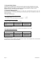
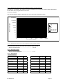
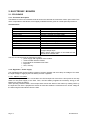
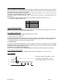
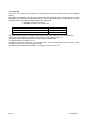
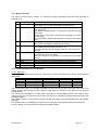
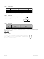
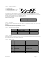
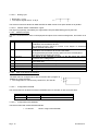
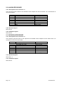
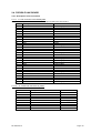
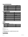
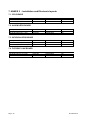
TECHNICAL MANUAL MASTER PCA NT 0850 Rev.0 TABLE OF MODIFICATIONS Information in this Technical manual only refers to devices belonging to the Master PCA. q File reference : ............ .............................NT 0850 q Revision date : ..........................................May 1999 q Applicability from serial N°........................16230001 Date Revision number Pages Modifications May 1999 rev AO All Creation Please note: No responsibility whatsoever can be taken by Fresenius Vial S.A for any fundamental change to product specifications (specifications, performance ratings, etc.) made by non-company technician. Small repairs may be carried out by the appropriate maintenance team, at the discretion of the end user and subject to his or her responsibility. We nevertheless recommend that service personnel first attend a training course organised by Fresenius Vial S.A. It is possible that this document contains errors or typing mistakes. Changes may be made at regular intervals, for inclusion in subsequent editions.. Thank you for your understanding. COPYRIGHT © 1998 by Fresenius Vial S.A. This technical manual may not be reproduced in whole or in part without the written consent of Fresenius Vial S.A. Fresenius Vial S.A. - head office : Le Grand Chemin - 38590 Brézins (FRANCE) - With directory and suprevision board, capital : 90128000 F - SIREN Grenoble B 408 720 282. NT 0850 Rev.0 NT 0850 Rev.0 TABLE OF CONTENT 1. OVERVIEW....................................................................................3 • • • • • 1.1. General description .................................................................................... 3 1.2. Block diagram ............................................................................................. 3 1.3. Precautions before use .............................................................................. 3 1.4. Internal safety features............................................................................... 4 1.5. Technical characteristics ........................................................................... 4 1.5.1. Device characteristics .......................................................................................... 4 1.5.2. Biological specifications ....................................................................................... 7 1.5.3. Mechanical characteristics ................................................................................... 7 1.5.4. Dimensions / Weight ............................................................................................ 7 1.5.5. Electrical characteristics...................................................................................... 7 1.5.6. Electronic characteristics...................................................................................... 7 1.5.7. Master PCA Operator’s Guide.............................................................................. 7 1.5.8. Components used for manufacturing .................................................................. 7 1.5.9. Compliance .......................................................................................................... 7 1.5.10. Registrations cards............................................................................................. 7 2. ELECTRONIC BOARDS ..............................................................8 • 2.1. CPU BOARD ................................................................................................ 8 2.1.1. Functional description .......................................................................................... 8 2.1.2. Regulation - Power supply.................................................................................... 8 2.1.3. Watch dog ............................................................................................................ 9 2.1.4. Communication modules.................................................................................... 10 2.1.5. Error message................................................................................................... 12 2.1.6. BUS I2C ............................................................................................................. 14 2.1.7. Master/ Pilot link ................................................................................................. 15 2.1.8. Command inputs and visualisation..................................................................... 15 2.1.9. Description of connectors................................................................................... 19 2.1.10. Electronic layout ............................................................................................... 21 2.1.11. Installation layout.............................................................................................. 21 • 2.2. ALARM LEDS BOARD............................................................................... 22 2.2.1. Description of the connector J1.......................................................................... 22 2.2.2. Electrical layout - ................................................................................................ 22 2.2.3. Installation layout................................................................................................ 22 • 2.3. INFUSION LEDS BOARD .......................................................................... 22 2.3.1. Description of the connector J1.......................................................................... 22 2.3.2. Electronic layout . ............................................................................................... 22 2.3.3. Installation layout................................................................................................ 22 • 2.4. FLEXIBLE LINK BOARD ........................................................................... 23 2.4.1. Description of the connectors............................................................................. 23 2.4.2. Electronic layout . ............................................................................................... 24 2.4.3. Implantation layout ............................................................................................. 24 3. CONFIGURATIONS, CALIBRATIONS AND CHECK .................24 • 3.1. Configurations .......................................................................................... 24 3.1.1. Configuration EPROM ........................................................................................ 25 3.1.2. Flash EPROM configuration ............................................................................... 25 • • 3.2. Calibrations ............................................................................................... 25 3.3. Check ......................................................................................................... 25 3.3.1. Electrical safety tests.......................................................................................... 25 3.3.2. Integrated tests................................................................................................... 25 3.3.3. Test mode .......................................................................................................... 25 NT 0850 Rev.0 Page : 1 4. REPLACING SUB-ASSEMBLIES............................................... 29 • • • • 4.1. Replacing the electronic circuit boards................................................. 29 4.2. Dismounting the support ......................................................................... 29 4.3. Replacing the flexible circuit ................................................................... 29 4.4. Replacing the handle ................................................................................ 29 5. MAINTENANCE .......................................................................... 30 • • • • 5.1. Cleaning and disinfecting ........................................................................ 30 5.2. Storage ....................................................................................................... 30 5.3. Servicing .................................................................................................... 30 5.4. Regular inspections - Preventive maintenance ..................................... 30 5.4.1. Before using checking ........................................................................................30 5.4.2. Preventive maintenance .....................................................................................30 5.4.3. Internal historical saving battery .........................................................................31 6. ANNEX 1 : ILLUSTRATED PARTS LIST ................................... 33 • 6.1. Traceability ................................................................................................ 33 6.1.1. Introduction.........................................................................................................33 6.1.2. traceability table..................................................................................................34 • • 6.2. General view .............................................................................................. 36 6.3. Mechanical parts list ................................................................................. 37 6.3.1. Aluminium support..............................................................................................37 6.3.2. Front panel .........................................................................................................37 6.3.3. cover...................................................................................................................38 6.3.4. Locker.................................................................................................................38 • 6.4. Electronic parts list ................................................................................... 39 6.4.1. Programmation pass ..........................................................................................39 6.4.2. Control and command ........................................................................................39 6.4.3. Electronic............................................................................................................39 6.4.4. Patient hand switch ............................................................................................39 6.4.5. Connectors .........................................................................................................39 7. ANNEX 2 : INSTALLATION AND ELECTRONIC LAYOUTS .... 40 • • • • 7.1. CPU BOARD............................................................................................... 40 7.2. ALARM LEDS BOARD............................................................................... 40 7.3. INFUSION LEDS BOARD .......................................................................... 40 7.4. FLEXIBLE LINK BOARD ........................................................................... 40 8. ADDENDA AND INFORMATIONS............................................. 41 9. USEFUL ADDRESSES ............................................................... 43 Page : 2 NT 0850 Rev.0 1. OVERVIEW 1.1. General description Information in this document only refers to devices belonging to the Master PCA. No responsibility whatsoever can be taken by Vial Medical for any fundamental change to product specifications (specifications, performance ratings, etc.) made by non-company personnel. Routine repairs may be carried out by the appropriate maintenance team, at the discretion of the end user and subject to his or her responsibility. We nevertheless recommend that Maintenance personnel first attend a training course organised by Vial Medical. The symbol visible on the condensed instruction guide of the device, recommends the Operator Guide should be completely read, in accordance with the EN 60 601-1 Standard. 1.2. Block diagram 1.3. Precautions before use Please consult Operator’s guide NT 0850 Rev.0 Page : 3 1.4. Internal safety features The Master PCA is equipped with a continuous functions inspection system activated as soon as the Master is switched ON. Any failure or anomaly in the procedure is immediately detected. Nevertheless, qualified staff of your organisation or our After Sales Service should always be notified in case of abnormal functioning ( see useful addresses, chapter 9 ) 1.5. Technical characteristics The Master PCA is controlled by a keyboard and a rotary knob. The parameters input by the user, the infusion parameters, and parameters describing the instrument status may be visualised by means of a graphic LCD screen. 1.5.1. Device characteristics 1.5.1.1. Accuracy on average delivered flow rate. q Accuracy of the ............................................................... ± 1 % q Accuracy on the internal diameter of the syringes ..........± 2 % 1.5.1.2. Average accuracy on the bolus This table is valid for a Pilot Anæsthésia or a Pilot C. Syringe BD PLASTIPAK 20 cc BD PLASTIPAK 50 CC Volume 0,2 ml à 0,8 ml 0,2 ml à 2 ml < - 0,2 % < - 0,15 % average error Used tubing: SE 1400 S These measurements are performed in compliance with PrEN60 601-2-24 comply. 1.5.1.3. Bolus volumes and flow rates Syringe BD PLASTIPAK 20 cc BD PLASTIPAK 50 CC Volume 0,2 ml to 10 ml 0,2 ml to 30 ml Injection duration Flash to 15 min Flash to 15 min Minimum flow rate 0,8 ml/h 0,8 ml/h Used tubing: SE 1400 S The maximum flow rate is limited by the performances of Pilot C and Anæsthesia. See connected Pilot operator's guide to know the flow rate limitation. Page : 4 NT 0850 Rev.0 1.5.1.4. Exactness and accuracy of the displayed values of massic flow rate According to concentration and massic flow rate, the Master PCA rounds the result of volumic flow rate at the first lower value programmable on the Pilot. Conversion diagram : The following diagram allows to determine the error versus the programmed value 100000000 10000000 Massic flow rate (µg/h) 1000000 1% 100000 2% 10000 5% Max f low rate 1000 Min f low rate 100 10 1 0 .1 1 10 100 1000 10000 100000 Conc entration (µg/ml) 1.5.1.5. Exactness and accuracy of the displayed mass values of bolus As for the massic flow rate, the mass of the bolus is under rounded. q Error on bolus mass........ ................................ < - 0,5 % 1.5.1.6. Accuracy on time q Error on the locking time. ................................ < 1s 1.5.1.7. Syringes list 50cc / 60 cc B-D Perfusion • B-D Plastipak • Braun Omnifix 20 cc 50cc / 60 cc Fresenius P Spritze • • Sherwood Monoject • • • Ivac • Braun Perfusor • • Map Gliss LL • Didactic line France • Map Pic indolor • Didactic Perfusion • Terumo • Dispomed • Tutoject type T • Dipomed type P • Zeneca PFS • Fresenius Injectomat • NT 0850 Rev.0 20 cc • • Page : 5 1.5.1.8. Pressure limit The selection values of the pressure limit threshold are changeable by configuration from the key board.(See operator’s guide of the connected Pilot for the operating procedure and the display accuracy). The threshold values or the pressure limits applied by default are the ones programmed on the Pilot. 1.5.1.9. Pressure management q Occlusion pre-alarm and alarms. q Disconnection / pressure drop alarm. 1.5.1.10. Occlusion alarm delay according to the infusion flow rate Correspondences tables between occlusion alarm delay and programmed flow rate for three selectable pressure limits in three pre-adjuted threshold mode. These tables shows obviously that it is very interesting to choose, as soon as possible, the lowest alarm threshold to get the short test alarm delay. The variable threshold mode allows to select continuously the best adapted value. Syringe Flow rate Low limit 300 mmHg Medium limit 500 mmHg High limit 900 mmHg Bd Plastipak 50 cc 1 ml/h 16’20 30’25 49’50 5 ml/h 3’40 5’19 11’30 1 ml/h 6’20 12’35 17’45 5 ml/h 45’’ 1’45 3’05 Bd Plastipak 20 cc 1 bar = 750 mmHg = 1000 hPa Used tubing: SE 1400 S 1.5.1.11. Bolus volume at occlusion ending. When occlusion is detected, the anti-bolus system is activated. By measuring the pressing dynamic strength, the reduction of the bolus at occlusion ending is performed according to the specific characteristics of each selectable syringe. This principle allows to much reduce this bolus whoever the flow rate and the alarm threshold adjustment be. Syringe Bd Plastipak 50 cc Bd Plastipak 20 cc Flow rate Low limit 300 mmHg Medium limit 500 mmHg High limit 900 mmHg 1 ml/h < 0,1 ml < 0,2 ml < 0,2 ml 5 ml/h < 0,1 ml < 0,2 ml < 0,2 ml 1 ml/h < 0,1 ml < 0,1 ml < 0,1 ml 5 ml/h < 0,1 ml < 0,1 ml < 0,1 ml 1 bar = 750 mmHg = 1000 hPa Used tubing: SE 1400 S q Note : The bolus reduction at occlusion ending is signalled by the alarm LED. Page : 6 NT 0850 Rev.0 1.5.2. Biological specifications Infusion liquid only comes into contact with the syringe and associated disposable. 1.5.3. Mechanical characteristics The mechanical system consists of an aluminium support hinged to the front casing. The electrical connections and installation are effected by pushing the Pilot backwards into the support (see the Master PCA Operator’s Guide). The casing is then lowered and locked onto the Pilot. On the button side two holes to insert fixing screws are available. 1.5.4. Dimensions / Weight • • • • Height : Width : Depth : Weight : 135 mm 370 mm 240 mm 1.9 kg approximately 1.5.5. Electrical characteristics The Master PCA is powered from a Pilot syringe pump. The power supply characteristics are as follows : • Power supply : 5.4V to 7.2V DC. • Max. consumption : 180 mA. • Max. power consumption : 1.3 W. 1.5.6. Electronic characteristics The Master PCA comprises the following electronic subassemblies : • CPU circuit board. • LCD graphic display. • Alarm LED circuit board. • Infusion LED circuit board. 1.5.7. Master PCA Operator’s Guide The Master PCA Operator’s Guide included operating cautions is available on request from our Customer Service. 1.5.8. Components used for manufacturing q Case................................Polycarbonate/ABS alloy q Control button .................Polyacetal q Fixing handle...................Polyamide q Protection hood...............Polycarbonate q Support ...........................Polyurethan painted aluminium q Keyboard.........................Polyester q Labels .............................Polyester 1.5.9. Compliance See Operator' s guide 1.5.10. Registrations cards Registration information is available upon request from our After Sales Service NT 0850 Rev.0 Page : 7 2. ELECTRONIC BOARDS 2.1. CPU BOARD 2.1.1. Functional description The Master PCA CPU circuit board is built around on the 80C320 microcontroler used in open mode. This micro is equivalent to the 80C32, but its slightly modified structure gives an overall speed improvement. Characteristics EPROM FLASH EPROM RAM EEPROM WATCH DOG INTERNAL CLOCK LED Driver Keyboard Driver Display T6963C integrated controller. Attachments RS 232 PC/ Master PCA. Power Supply 256 Ko 521 Ko 128 Ko saved by a battery 2 Kbytes for the instrument’s configuration MAX 691 resetable and safety RAM PCF 8583P addressable by IC bus 16 LED' s max 16 keys max. 128 x 64 pixel screen graphics Manual adjustment of contrast RS TTL Master PCA / Pilot RS 232 option Continuous from 5.4 V to 7.2 V, includes regulator of slight voltage drops. Battery power safety system for the RAM and the internal clock 3.6V 60 mAh. The CPU circuit board has the following functions : • power supply and regulation of the module. • communication with the module. • link module for the Master PCA/ Pilot . • keyboard. • CPU, memory. • 2.1.2. Regulation - Power supply The regulation/power supply module consists of a linear regulator with a low drop out voltage of for which the input voltage is supply by the Pilot battery and then regulated. 2.1.2.1. ON/OFF command The ON/OFF key of the device is connected to the CD ON input line of the Pilot. A short press on this key switch on the power supply of the Pilot. Then, the Pilot battery supplies the necessary energy to the Master PCA (mains or battery). When pressing ON/OFF button, the microprocessor knows the status of the button by reading TOFF by the input line from U24. It prepares the switch off mode and sends the command to turn off the voltage to the Pilot using RS 232 interface from the Pilot. Page : 8 NT 0850 Rev.0 2.1.2.2. Protection of the power supply In case of breakdown of power supply, the Pilot battery provides the necessary energy to the two devices. When the Master PCA is switched off, an internal battery saves the RAM in order to keep patient’s history, and the internal clock continues to be supplied. The battery is recharged when the device is in use. When the instrument is not in use, the minimum life expectation for a fully charged battery is 2 months. The battery voltage of the Pilot is present on the connector subD 15 points J2, connecting the Pilot to the Master PCA. • the minimum supplied voltage which does not provoke the resetting of the device is 5.1 V. • the maximum supply voltage is 7.2 V . J2 Description 6 VBAT 14 VBAT 5 GND 13 GND 2.1.2.3. Pre-alarms and alarms Alarms and pre-alarms are identical to those of the Pilot. The alarm status parameters of the Pilot is transmitted via the RS 232 interface to the Master PCA. 2.1.2.4. Battery voltage levels This voltage is measured at the battery terminals lead of the Pilot. • pre-alarm : 5,8 V min / 6,0 V max. • alarm : 5,6 V min / 5,8 V max. The voltage drop between the input of the instrument’s regulator and the battery is due to the internal fuse of the Pilot and various connections between. This voltage drop is 0.5 V max. for a current of 350 mA. • the battery voltage of the Pilot can be measured inTP4 2.1.3. Watch dog The watch dog manage the RESET line, the rising voltage of VP of the circuit voltage Vp to safety (RAM, INTERNAL CLOCK), the switching of the CE line of the RAM to keep the integrity of the data in the RAM in case of drop of the power supply is broken. The voltage V.P. is supplied by the battery BT1. The timer is activated by the signal WDOG generated by the output socket comprised of circuit U22 ( 2.1.3.1. Voltage of Power Supply the signal RESET is activated for a standard voltage value, after regulation, of : 4,65 V ± 0,15 V. 2.1.3.2. Resetting • maximum reset time of WDOG : 100 ms. 5.00 V 4. 65 V • activation of signal RESET : 200 ms. 0V • power supply voltage = 5.00 V ± 0.25 V. Res et WDOG T < 1 0 0 ms T < 1 00 ms NT 0850 Rev.0 Page : 9 2.1.4. Communication modules The CPU circuit board has 3 serial interface plug. Connection socket for the Master PCA/ Pilot . • RS 232-1 plug. • RS 232-2 plug (optional). 2.1.4.1. Plug socket for the Master PCA/ Pilot Series linking TTL of full duplex communication between the Pilot and the CPU. 2.1.4.2. Communication Master PCA/ Pilot Two-directional series link TTL Transmission data speed : 4800 Baud set value 31250 Baud by software configuration Transmission data format : 1 start bit 7 data bit 1 even parity bit 1 stop bit The signals are found on the male connector SubD 15 points J2 (connection Master PCA/ Pilot). J2 2 10 3 Description RXD Pilot TXD Pilot GND power supply 2.1.4.3. RS 232-1 connector This connector is used for several types of communication. 2.1.4.3.1 Connection PC/ Master Bi-directional series data RS 232-1 Bus Transmission data speed : Transmission data format : Page : 10 4800, 9600, 19200 Baud selectable in configuration menu 1 start bit 7 data bit 1 even parity bit 1 stop bit NT 0850 Rev.0 2.1.4.3.2 Communication Master/ Printer This mode is permanently available when the instrument is being used to print histories. Bi-directional link RS232 : Transmission speed : Transmission format : 9600 Baud 1 start bit 8 data bit 0 parity bit 1 stop bit The control of flux is carried out by a hardware link between the DTR pin of the printer to the RTS pin 8 of the Master PCA. • When the RTS pin is at + 12 V, the Master PCA considers that the printer is ready to receive some text. • When the printer is not connected, the RTS pin is set to - 12 V ; and the PCA therefore sends no text. The socket signals for the 3 modes of communication are found on the female connector SubD 9 points J7. J7 Description 2 RXD 3 TXD 7 CTS 8 RTS 5 GND 2.1.4.4. RS 232-2 connector (Optional) The unused series link RS 232 is reserved for future extensions. The socket signals are found on the female connector sub D 9 points J6. J6 2 3 7 8 5 NT 0850 Rev.0 Description RXD TXD CTS RTS GRD Page : 11 2.1.5. Error message During the process of linking between the Master PCA and the Pilot . The following types of breakdown are detected and displayed on the LCD display screen. Three types of messages are displayed: q Alarms: Code 10 Description Low battery Variable state bit 10 11 Wrong position of the syringe bit 4 12 Empty syringe bit 9 14 Disengagement bit 7 15 Syringe head bit 5 16 Occlusion bit 6 18 Dose limit reached bit 14 19 Wrong position of the syringe bit 13 22 Occlusion memory bit 2 23 Battery alarm 25 Flange detection q Recoverable errors They allow to continue to use the device after their detection. Code 01 Description Rotation control 32 Displacement control (on one segment) 52 Displacement control(during slack adjustment) 72 Displacement control (on total length) 82 Displacement control (versus flow rate) Page : 12 NT 0850 Rev.0 q Locking errors The locking errors, worst, allow only to switch off the device by the ON/OFF to release. Code 40 Description Pilot E2prom 50 Pilot ADC 60 syringe parameters 70 Motor frequency 03 Pilot communication 13 Absent Pilot 23 Link to pilot closed 33 Reception 43 Transmission 53 No answer from Pilot 63 Bad Pilot answer 73 Bad Pilot type 83 Bad Pilot version 93 Master activation mode 14 period verification 24 Rotating direction check 34 Motor period check 15 Ram Master (internal) 25 Ram Master (external) 35 EPROM Master 45 E2prom Master 55 Internal clock 65 LCD Ram 75 Uarts 16 Date / time verification 26 Date / time comparison 46 Bad records history 18 Infusion maximum value reached 28 incorrect language file 48 Volume control on motor impulse 58 Flow rate control on motor impulse 68 Stop check 78 Maximum duration NT 0850 Rev.0 Page : 13 2.1.6. BUS I2C The I2C bus is a series bus synchronous in communication with the internal clock and the EEPROM memory. With regard to overlapping memory space between the two peripherals and to the fact that they are not addressable simultaneously, a single clock CLK I2C ensures the synchronicity of data transfer, two lines of transfer make sure of the exchange between each peripheral. • EEPROM : 2 Kbytes 24C16 U13 • INTERNAL CLOCK : PCF 8583 P U21 Line of communication CLK : clock generated by the microprocessor SDA EEPROM : line Bi-directional exchange SDA HORO : line Bi-directional exchange Socket U22.19 P 1.0 P 1.1 The clock is built around the circuit PCF 8583. It provides the day of the year, the month and hour. Voltage Vp of the battery BT1 ensures it is functioning via the RESET circuit, U11. The system clock is generated by quartz X3 with frequency 32,768 kHz. The signal frequency of HORO is 1 Hz. A frequency control is carried out by an internal timer of the microprocessor and the value is then compared to the run time read by the bus CLK I2C. -6 Any differences are detected immediately. The frequency must be 1 Hz ± 10 . Page : 14 NT 0850 Rev.0 2.1.7. Master/ Pilot link The linking connector Pilot / Master, J2, carries the logical information other than that described in paragraph 2.4. . J2 1 Name MAINS LED 9 ON KEY 11 BUZZER 4 OPTO MOTOR 12 OFF KEY 6 14 5 13 VBAT VBAT GND GND Function The Pilot tells the Master PCA that the supply is connected. The battery is in use when the signal is at logical level 1. The ON button on the front panel is connected in parallel with that of the Pilot. The Master’s ON/OFF button is connected to the input CD ON of the Pilot. A short push of the button provokes the switching-on the Pilot power supply. The Pilot battery supplies the necessary energy to the Master PCA. The Master PCA uses the Pilot’s buzzer. The buzzer is activated by setting this line to zero. This signal is sent from the Pilot towards the instrument and then redirected towards the input pin U1-16 . This line generates an impulse with each turn of the motor from the Pilot This signal tells the Master PCA that the Pilot has received a command to turn off the voltage. This line changes to logical level 1 to prepare for the voltage turn-off. This line provides the energy supply from the Pilot battery. This line provides the energy supply from the Pilot battery. — — 2.1.8. Command inputs and visualisation 2.1.8.1. Keyboard The keyboard is organised as a matrix of 4 lines and 4 columns. The role of each button is described the table below : column 0 column 1 column 2 column 3 line 0 ENTER (Rotary knob) line 1 line 2 line 3 ENTER (keyboard) ALARM SILENCE PRIME NEW PATIENT START DISPLAY HISTORY STOP The two ENTER buttons are operated separately but have the same effect. The diodes D2 to D5 act to protect against short circuiting of the outputs of U26 when two buttons of the same line are pressed simultaneously. The columns are activated for a logical level 0 by writing in U26 at address $1000. The status of each button for lines 0 to 3 is read by a logical level 0 from the time of activation through reading the buffer U33 at address $2000. The ON/OFF button is connected to the input CD ON of the Pilot via the flexible plate link (see Flexible plate link). The ON/OFF button is activated by a logical level 0. The status of the ON/OFF button is known by the CPU by reading one of the inputs of U5 set at the address $2800. NT 0850 Rev.0 Page : 15 2.1.8.1.1 Written register U26 D0 D1 D2 D3 Address $5000 COLUMN 0 COLUMN 1 COLUMN 2 COLUMN 3 Set to zero at the RESET J11-5 J11-6 J11-7 J11-8 Active to 0 The data are reproduced at the outputs of U26 by a upright front on U 26-11. Only one column is activated at a time. 2.1.8.1.2 Writing cycle • Time between two successive readings : 5 ms • Time kept at logical level 0 : 5 µs • Refresh period : 20 ms. U26.2 U26.5 U26.6 U26.9 2.1.8.1.3 Read register U24 D4 D5 D6 D7 Address $2800 LINE 0 LINE 1 LINE 2 LINE 3 J11-1 J11-2 J11-3 J11-4 After the addressing of each column, the status of the lines 0 to 3 are read simultaneously through the buffer U5 on the data bus. 2.1.8.2. Coder 2.1.8.2.1 Rotation The coder is a two phases (A, B), incremental type one It includes a push button having the same function as the ENTER key. The two phases are dry contacts, the common is earthen. B A C Page : 16 NT 0850 Rev.0 2.1.8.2.2 • • • • Coder characteristics Functioning 30 impulses/ 360° contacts normally open Max intensity per contact : 10 mA min intensity per contact : 1 mA chronogram: Channel A Channel B CW rotation forward cCW rotation backward The signals from A and B are filtered to remove any erroneous coding due to rebounds of the contacts. A decoding consisting of a PAL U15 generates information for both decrementation and incrementation DEC, INC, which are reset to zero by the signal RAZ BOUTON. The information INC, DEC is read by the data bus every 5 ms. Read and written register U D0 D1 2.1.8.2.3 Address $1800 DEC INC Push button The coder includes a key-sensitive push button having the same function as the enter button on the keyboard. Pressing the push button provokes the closure of the contact. The contact is connected to the keyboard matrix. 2.1.8.2.4 Description of the coder cable J14 1 2 3 4 5 2.1.8.2.5 Description CHANNEL B CODER CHANNEL A CODER PUSH BUTTON CODER PUSH BUTTON CODER GND column 0 line 0 Indicators All the right indicators are electro-luminescent diodes. The status of each diode is defined by the level of the corresponding output in the registers U23 and U26. 2.1.8.2.6 Written records U23 D0 D1 D2 D3 D4 D5 D6 D7 U26 D4 D5 D6 D7 NT 0850 Rev.0 Address $800 INFUSION LED 1 INFUSION LED 2 INFUSION LED 3 INFUSION LED 4/START STOP LED OPEN BATTERY LED PRE ALARM LED Address $1000 ALARM LED OPEN OPEN PATIENT LED Set to zero at RESET J6.2 J6.3 J6.4 J6.5 J6.6 J6.7 J4.2 J4.5 Set to zero at reset J4.4 J4.7 J4.6 J2.12 Page : 17 2.1.8.2.7 Writing cycle • Reset time : 10 ms • Time kept at logical level 0 : 0.35 µs U23.11 The electro-luminescent diodes ALARM and PRE ALARM consist of two pairs diodes set in parallel. 2.1.8.2.8 "MAINS SUPPLY PRESENT" signal This signal is physically controlled by the signal Main LED (LED SECTEUR) given by the Pilot. 2.1.8.3. Additional outputs The CPU circuit board has some unused peripheral outputs for its internal management, and others not in use. U22 Address D0 PG-RAM0 D1 PG-RAM1 D2 RTS OPT D3 WDOG D4 D5 D6 D7 CD CLEF CD CAPOT CD PATIENT. CLK I2C . 2.1.8.4. Description This signal allows the addressing of the RAM U6 to be extended in combination with the address bit A15. The decoded memory space is a block of 32 Kbytes of addresses between $10000 and $1FFFF. This signal allows the addressing of the RAM to be extended in combination with the address bit A15 and PG-RAM1. The supplementary decoded memory space is a block of 32 Kbytes of addresses between $20000 et $3FFFF. This signal is the “Request to Send” of the RS 232-2 link before conversion of the voltage level. This signal is connected to the input WDI of U11. It’s the activation signal for the watch-dog. This signal allows to detect the key state. This signal allows to detect the hood state. This signal allows to detect the patient hand set state. This signal is the clock for activation of the bus I2C. CPU circuit board configuration The CPU board is configured to be able to function with a program in EPROM or in flash EPROM. • The configuration is carried out by contacts G1, G7 and G6. 2.1.8.4.1 1 2 3 Configuration EPROM The circuit board can be fitted out with an EPROM 27C512 to 27C040, of 100 ms access time. G1 and G7 G6 G6 2.1.8.4.2 open 2.3 1.2 EPROM type EPROM 27C010, 020, 040 EPROM 27C512 Configuration flash EPROM The board is fitted with a flash EPROM 28F004. • G1 and G7 Page : 18 closed using FLASH EPROM NT 0850 Rev.0 2.1.9. Description of connectors 2.1.9.1. J2 : connection to the Pilot and external peripherals This connector is attached to a flexible plate which redistributes signals to the Pilot and to the external connectors. Pin 1 2 3 4 5 6 7 8 9 10 11 12 13 14 15 16 17 18 19 20 21 22 23 24 25 26 27 28 29 30 Description GND RTS TXD RIS RXD GND CTS TXD RTS RXD V BAT PATIENT LED PATIENT CD PATIENT CALL GRD LOCK CD ILS LOCK VBAT VBAT GND GND TP8 CTR MOT CD BUZZER GND TXD RXD TON LED SUPPLY GND power supply printer printer printer printer power supply option option option option power supply LED patient hand switch patient hand switch input patient hand switch output power supply hood state input hood state output power supply power supply power supply power supply not in use motor rotation BUZZER command power supply Pilot Pilot stop command supply presence power supply 2.1.9.2. J3 : connector for LCD display Pin 1 2 3 4 5 6 NT 0850 Rev.0 Description GND GND + 5V BACK PLANE WR* RD* power supply power supply power supply polarisation display transmission control line reception control line Page : 19 7 8 9 10 11 12 13 14 15 16 17 18 CD LCD A00 RESET* D0 D1 D2 D3 D4 D5 D6 D7 GND line for validation of memory space line address A00 initialisation display data line D0 data line D1 data line D2 data line D3 data line D4 data line D5 data line D6 data line D7 power supply 2.1.9.3. J4 : alarm display connector Pin 1 2 3 4 5 6 7 8 Description GND BATTERY LED SUPPLY LED ALARM LED PRE-ALARM LED NU NU GND power supply alarm circuit alarm circuit alarm circuit alarm circuit not in use not in use power supply 2.1.9.4. J6 : infusion display connector Pin 1 2 3 4 5 6 7 8 Description GND INFUSION 1 LED INFUSION 2 LED INFUSION 3 LED INFUSION 4/START LED STOP NU GND power supply power supply power supply power supply On signal Stop signal not in use power supply 2.1.9.5. J8 : Volume control connector Pin 1 2 Description Motor impulse Motor direction Volume control not in use 2.1.9.6. J9 : connector back light of the display Pin 1 2 Page : 20 Description BACK LIGHT ANODE +5V BACK LIGHT CATHODE back light anode back light cathode NT 0850 Rev.0 2.1.9.7. J10 : debug connector Pin 1 2 3 4 5 6 7 Description GND WR* RD* INT UART RESET* DEVAL A15 power supply transmission control line reception control line Interruption line 0 reset line peripheral validation line of address A15 2.1.9.8. J11 : keyboard connector Pin 1 2 3 4 5 6 7 8 9 10 Description LINE 0 LINE 1 LINE 2 LINE 3 COLUMN 0 COLUMN 1 COLUMN 2 COLUMN 3 T ON OFF GND keyboard matrix line keyboard matrix line keyboard matrix line keyboard matrix column keyboard matrix column keyboard matrix column keyboard matrix column ON/OFF power supply 2.1.9.9. J12 : power supply monitor connector Pin 1 2 Description VBAT FILTRED GND filtered power supply power supply 2.1.9.10. J14 : connector coder Pin 1 2 3 4 5 6 7 8 9 10 Description CHANNEL B CODER CHANNEL A CODER GND CODER PUSH BUTTON CODER PUSH BUTTON GND +5V CD KEY CD KEY GND decoding PAL decoding PAL power supply keyboard matrix keyboard matrix power supply power supply key presence detector not in use power supply column 0 line 0 2.1.10. Electronic layout See Annex 2. 2.1.11. Installation layout See Annex 2. NT 0850 Rev.0 Page : 21 2.2. ALARM LEDS BOARD 2.2.1. Description of the connector J1 This connector joins the LED’s to the elevated current outputs from the CPU board. It is connected via J4 on the CPU board. Pin 1 2 3 4 5 6 7 8 Description GND MAIN LED MAIN LED ALARM LED PRE ALARM LED NU NU GND power supply alarm circuit alarm circuit alarm circuit alarm circuit not in use not in use power supply 2.2.2. Electrical layout See Annex 2 2.2.3. Installation layout See Annex 2. 2.3. INFUSION LEDS BOARD 2.3.1. Description of the connector J1 This connector joins the LED’s to the outputs at an elevated current outputs from the CPU board. It is connected via J6 on the CPU board. Pin 1 2 3 4 5 6 7 8 Description GND INFUSION LED 1/ON INFUSION LED 2 INFUSION LED 3 INFUSION LED 4 LED STOP NU GND power supply infusion circuit infusion circuit infusion circuit infusion circuit infusion circuit not used power supply 2.3.2. Electronic layout . See Annex 2. 2.3.3. Installation layout See Annex 2. Page : 22 NT 0850 Rev.0 2.4. FLEXIBLE LINK BOARD 2.4.1. Description of the connectors 2.4.1.1. J1 : link connector to the flexible plate This connector joins the Pilot and the RS 232 input socket to the CPU board. Pin Description 1 GND power supply 2 CTS printer 3 TXD printer 4 RTS printer 5 RXD printer 6 GND power supply 7 CTS option 8 TXD option 9 RTS option 10 RXD option 11 VBAT power supply 12 LED INF hand switch Led anode 13 RETURN PATIENT CALL hand switch LED cathode 14 CD PATIENT CALL not in use 15 GND power supply 16 RETURN ILS LOCK hood contact 17 CD ILS LOCK hood contact 18 VBAT power supply 19 VBAT power supply 20 GND power supply 21 GND power supply 22 OFF BUTTON not in use 23 OPTO MOTOR rotation motor 24 BUZZER start command for the BUZZER 25 GND power supply 26 TXD MASTER Pilot 27 RXD MASTER Pilot 28 ON BUTTON ON/OFF switch 29 LED SUPPLY supply presence 30 GND power supply 2.4.1.2. J7 : series link connector for printer Pin 1 2 3 4 5 6 7 8 9 NT 0850 Rev.0 Description NC RXD TXD NC GND NU RTS U CTS NU not in use printer printer not in use power supply not in use printer printer not in use Page : 23 2.4.1.3. J6 : optional series link connector Pin 1 2 3 4 5 6 7 8 9 Description NC RXD TXD NC GND NC RTS CTS NC not in use option option not in use power supply not in use option option not in use 2.4.1.4. J2 : connector linking Pilot Pin 1 2 3 4 5 6 7 8 9 10 11 12 13 14 15 Description LED SUPPLY RXD MASTER GND OPTO MOTOR GND VBAT NU NU ON BUTTON TXD MASTER BUZZER OFF BUTTON GND VBAT NU supply presence Pilot power supply rotation motor power supply power supply not in use not in use ON/OFF switch Pilot buzzer command stop button power supply power supply not in use 2.4.1.5. J3 : not installed 2.4.1.6. J5 : hand set connector This connector is destined to be used in PCS mode. Pin Description 1 CATHOD 2 HAND SET CONTACT 3 HAND SET CONTACT 4 ANOD Hand set LED hand set contact hand set contact Hand set LED 2.4.2. Electronic layout . See Annex : 2. 2.4.3. Implantation layout See Annex : 2. 3. CONFIGURATIONS, CALIBRATIONS AND CHECK 3.1. Configurations CPU board configuration Page : 24 NT 0850 Rev.0 CPU board is configurable to work with an EPROM or FLASH EPROM program. Configuration is carried out by the drops G1, G7 et G6. 3.1.1. Configuration EPROM The board can be equipped with a 27C512 to 27C040 EPROM, access time : 100 ms. 1 2 3 G1 et G7 G6 G6 open 2.3 1.2 EPROM use EPROM 27C010, 020, 040 EPROM 27C512 3.1.2. Flash EPROM configuration The board is equipped of a 28F004 flash EPROM G1 et G7 closed For the other configurations see operator’s guide. FLASH EPROM use 3.2. Calibrations Aimless 3.3. Check 3.3.1. Electrical safety tests In compliance with EN 60 601.1 complies. 3.3.2. Integrated tests The device has integrated auto-tests of the following components : q Screen . q LED’s . q Keyboard . q Rotary knob . q Serial links . q Internal clock. The tests can be perform with a Pilot CE 0459 or with an external power supply of 7 V via the 15 points sub D connector. The following polarisation must be respected in this case. The pin 10 should be connected to the pin 2. Pin 6 14 5 13 2 10 Description +7V +7V GND GND RXD TXD Power supply Power supply Power supply Power supply Pilot Pilot 3.3.3. Test mode Press the two buttons simultaneously during the instrument auto-test SILENCE NT 0850 Rev.0 + START . Page : 25 Manual procedures Press to activate servicing procedures Functionning duration Evolution time Software version LCD screen test LEDs test The screen shown here invites the user to enter the test mode by pressing ENTER . If the user doesn’t quickly validate the entry into this mode, the instrument will return to the programming menu. A turn of the Dial information. Pressing STOP selection menu. allows the user to select the type of test or to display allows the user to leave the test and return to the select function 3.3.3.1. Functioning duration Functioning duration Total:02 months 12 days 10 hours since 28/26/1998 10:36 date modification This screen displays the following information : - total instrument running time. - total usage time since the last use. The instrument assumes that the average length of a month is 30 days. Successive action on and allows one to change the maintenance date. The time elapsed since the last maintenance is renewed after modification of the maintenance date. 3.3.3.2. Evolution dates Evolution time Flash 30/01/1996 15:12 This screen displays the last evolution dates and time : - date and time of loading the Master PCA application in flash memory. . exit 3.3.3.3. Software version Software version Master PCA V02.2a 29/09/1997 (56B7) This screen displays the numbers of the software versions : - version, revision of the Master PCA application. - date generated and the checksum of the software. next Language version English V01.0 27/09/1996 review Pressing displays the language screens : - language. - version, revision of the files as well as the creation date of the language. All the different screens can be consecutively displayed using the rotary knob. 3.3.3.4. Screen LCD test This test alternates between lighting all the pixels then every odd pixels, even pixels. 3.3.3.5. LED' s test LED’s test This screen shows the status of the display LED’s. At the onset of this test, all the LED’s are illuminated at the same time for 3 s. exit Page : 26 NT 0850 Rev.0 3.3.3.6. Keyboard test This screen shows the positions of the buttons according to the following order : - squares 1 to 4 : line 0 column 0 to 3. - squares 5 to 8 : line 1 column 0 to 3. - squares 9 to 12 : line 2 column 0 to 3. - squares 13 to 16 : line 3 column 0 to 3. Keyboard test exit (2s) As soon as the button is pressed the corresponding symbol appears on the screen in the case according to how its matrix is organised. To stop the test, it is necessary to hold down the STOP button for more than 2 seconds. 3.3.3.7. 3.3.3.7. Rotary knob test This screen shows the number of impulses made by the rotary knob in rotating as well as an indication of the speed by means of a bar-graph. The sense of rotation is the same as that shown on the horizontal scale. - a single bar corresponds to slow speeds. - two bars correspond to greater speeds. Rotary knob test 0 exit 3.3.3.8. 3.3.3.8. Patient switch test cover open no key missing switch exit 3.3.3.9. 3.3.3.9. RS 232 link test Tx/Rx Tx/Rx Rts/Cts PC err err Option err err Pilot ok err err internal ok 3.3.3.8 Patient switch test This screen shows the state of the cover, programmation key and patient switch Important : to check Hand set functionality, the wiring layout must be respected. - 1 : Patient switch LED cathode - 2 : Patient switch contact - 3 : Patient switch contact - 4 : Patient switch LED anode 3 2 4 1 Serial link test Before carrying out this test, it’s necessary to fitted the device with test plugs made from subD 9 points with TxD and RxD links and a second link between CTS and RTS. This plug equip the RS232-1 links (PC link). This screen shows the states of the different serial link lines. If one link is defective, the error message will appear. 3.3.3.10. Latest events Latest alarm codes 03/08/1998 10:05 Alarm 11 Syringe positionning This test allows to check the last 10 events. Each event is display on one screen-page, each screen-page is selected with the rotary knob The events are numbered chronologically with the last as number 1. review The possible errors are out of 3 types : see §2.15 for details 3.3.3.11. Clock period Timekipper period 1.000 s This screen displays the measurement of the internal period clock which is cyclically updated. For correct functioning of the instrument, the displayed value must equal 1.000 s. exit 3.3.3.12. Pilot information This test extracts information on the latest 3 connected Pilots. Each Pilot number is displayed on one screen-page, and each page is selected using the rotary knob. The different screens are numbered chronologically with the most recent numbered 1. NT 0850 Rev.0 Page : 27 Pilot Information 1 Pilot: PIL D SN: 015711/16025624x V07.0B 10/09/1996 (738C) This screen displays the following information : - Pilot type. - series number of the Pilot. - software version of the Pilot. - date and checksum of the Pilot EPROM. 3.3.3.13. Battery load Battery test Page : 28 This is a timer to indicate the time spent during the menu enter after 96 hours charge, the bargraph is full and indicates that the RAM battery is fully charged. To charge this battery: • Connect the device to main. • Go to test mode. • Select : battery load • Charge for at least 96 hours Exit this menu reset and stop the timer. NT 0850 Rev.0 4. REPLACING SUB-ASSEMBLIES Important : a complete check of the instrument must be made after any internal investigation. 4.1. Replacing the electronic circuit boards Important : be very careful with the flexible plate on opening the device. 1. Remove the 7 screws in the front face, and detach the fixing clamp. 2. Disconnect the LCD flat cable, taking care not to damage it. 3. Disconnect the connection cables from the keyboard connector, the display circuit connectors the coder connector and the flexible plate connector. 4. Take out the board, very carefully. 5. Replace the LED or the keyboard circuit if necessary. 4.2. Dismounting the support Remove the two fixing screws on the hinge situated next to the CPU circuit board and pull. 4.3. Replacing the flexible circuit Note : dismantling the flexible circuit systematically implies its replacement. 1. Dismantle the two connector support plates. 2. Detach the flexible circuit from the aluminium support. 3. Detach the connectors from their plate support. 4. Clean the glue from the surface with 95° methylated spirits. 5. Remove the protective sheet from the new flexible circuit, equipped with its connectors. Glue the flexible circuit making sure it is well positioned with regard to the 2 fixing screw-holes in the Pilot / Master PCA. 6. Glue on the protective film of the flexible circuit. 4.4. Replacing the handle 1. 2. 3. 4. 5. Unscrew the handle until it unclips from its socket and remove the screw from its thread. Unscrew the plate enclosing the mechanism situated below the support. Disengage the 2 wingnuts from their housing with pliers and pull out the set. Insert a new handle into its socket. Fix back the lock support plate or change the faulty parts of the lock. NT 0850 Rev.0 Page : 29 5. MAINTENANCE 5.1. Cleaning and disinfecting The Master PCA is part of the patient’s immediate environment. It is advisable to clean and disinfect the device’s external surfaces on a daily basis in order to protect patient and staff.Disconnect the device from its mains supply before starting to clean. • Do not place in an AUTOCLAVE nor IMMERSE the device. Do not let liquids enter the device’s casing. • If the device is placed in a high contamination risk unit, it is advisable to leave it in the room during aerial disinfecting, after having disinfected it with a moist cloth. • Use a cloth soaked in DETERGENT-DISINFECTANT, previously diluted with water if required, to destroy micro-organisms. Avoid abrasive scrubbing which could scratch the casing. Do not rinse or wipe surfaces. • Do not use: TRICHLOROETHYLENE-DICHLOROETHYLENE - AMMONIA - AMMONIUM CHLORIDE - CHLORINE and AROMATIC HYDROCARBON - ETHYLENE DICHLORIDE-METHYLENE CHLORIDE - CETONE. These aggressive agents could damage the plastic parts and cause device malfunction. • Take care also with ALCOHOL BASED SPRAYS (20% - 40% alcohol). They lead to tarnishing of and small cracks in the plastic, and do not provide the necessary cleaning prior to disinfecting. Using disinfecting applies by SPRAYS may be done, in accordance with the manufacturer recommendation, from a distance of 30 cm of the device, avoid the accumulation of the product in liquid form. Please contact the appropriate service, handling suitable cleaning and disinfecting products, in your establishment for further details. 5.2. Storage The device should be stored in a dry, cool place. In case of prolonged storage, the battery should be disconnected via the battery access flap situated underneath the device. This should be done by a qualified technician. • Storage temperature: -10°C + 60°C. • Permissive relative humidity: maxi 85%, no condensation. 5.3. Servicing To ensure normal performance of the device, it is recommended to replace the internal battery each 3 years. This should be done by a qualified technician. The qualified technicians in your establishment or our After-Sales Service should be informed if the device is dropped or if any of malfunction occurs. In this case, the device must not be used. For further information concerning the pump servicing or its use, please contact our After-Sales Service or our Customer service. If the device has to be returned to our After-Sales Department, proceed to its cleaning and disinfecting. Then , pack it very carefully, if possible in its original packaging, before sending it with a detailed description of the fault, to the official representative of Vial Medical. Vial Medical is not liable for loss or damage to the device during transport to our After-Sales Department. 5.4. Regular inspections - Preventive maintenance 5.4.1. Before using checking (See operator' s guide of Master PCA : §14.2 page 28) This check must be performed before every use of the Master Note : In the framework of continuous improvement, this checklist may change any time. Please contact our after sales service for up-to-date version.( Addresses at the end of this document) 5.4.2. Preventive maintenance (See next page : Technical check certificate) In order to insure preventive maintenance, preventive technical check is recommended every 24 months. This technical check must be performed by qualified technician and is not covered by any contract from FRESENIUS VIAL. For more information contact After Sale Service.( Addresses at the end of this document) Page : 30 NT 0850 Rev.0 5.4.3. Internal historical saving battery • Changing Internal historical saving battery is recommended every 2 years • Changing this battery obliged to dismount CPU board following procedure described in § 4.1. • Deweld battery, avoiding excess heating, short circuit and electrostatic charges when manipulate the board. • The place of the battery is marked by a sticker. • Prior placing a new battery make sure implant direction is correct and polarities are in accordance with serigraphy. • Battery type is : 60 mA, CdNi, weldable Gb. • Use procedure set up by battery maker to destroyed the removed battery. NT 0850 Rev.0 Page : 31 Technical check certificate --> See STK - Protokoll . Page : 32 NT 0850 Rev.0 . 6. ANNEX 1 : ILLUSTRATED PARTS LIST 6.1. Traceability 6.1.1. Introduction The aim of this chapter is to guide technicians looking for spare parts when servicing the device. NT 0850 Rev.0 Page : 33 6.1.2. traceability table Serial number UC Card Rotating coder Magnet Magnet support Page : 34 From :....16230001 To :........16470140 182004 182997 182208 182408 From :......1670141 To :...........1653270 182004 182997 182232 182408 From.......16530271 182004 182989 182232 182408 NT 0850 Rev.0 NT 0850 Rev.0 Page : 35 6.2. General view 42 62/66 41 65 5 1 4 8 11 7 63 10 6 3 61 64 12 14 60 9 35 13 36 16 23 40 25 72 73 57 38 71 33 21/22 69 24 28 68 70 26 39 29 30 57 32 54 31 34 47 48/49 43/44/45 51/52 Page : 36 50/52 53 NT 0850 Rev.0 6.3. Mechanical parts list 6.3.1. Aluminium support Ref.: Rep: Quantity 182161 1 1 External support plate 182705 3 1 Communication foam joint 182106 4 1 Moulded complete handle 182705 5 1 External support foam joint 182157 6 1 Pilot communication plate 182205 7 1 Aluminium PCA support 182108/ 8 1 Handle screw end 199593 9 2 Inox M 5* 6 split screw 199597 2 Sub d lg6 spacer 199599 10 Black TF M 3*8 Taptite screw 12 1 Flexible circuit protection Ref.: Rep: Quantity 182226 21 1 Front panel hinge 182703 22 1 Hinge plate joint 182702 23 1 Plate band joint 182124 24 1 Master lever locker lever 182155 25 1 Front panel plate 199587 26 5 ff 10h3050-5 spacer 199591 27 1 Inox Z1 M 3*40 TCB screw 182407 28 1 PCA technical closer 182128 29 1 PCA front panel 182012 30 1 Anti-blink LCD screen 182779 Description 6.3.2. Front panel NT 0850 Rev.0 Description Page : 37 6.3.3. cover Ref.: Rep: Quantity Description 190096 43 2 Nylon washer 182401 44 2 ACME 0180400 pillow-block 199570 45 2 CB M 4*16 screw 199534 46 2 Flat inox ZAN washer 182408 47 1 57050 overmoulded magnet 182223 48 1 PCA magnet support 199602 49 2 Black TF 2.5 split screw 182229 50 1 Left pin 182228 51 1 Right pin 199605 52 1 Polyamide TF M2 * 6 Nylon screw 182227 53 1 PCA cover 182207 54 1 PCA locking plate Ref.: Rep: Quantity 182162 60 1 PCA handle mechanism closer 182222 61 1 Lock bolt 182224 67 1 Cover hook 182402 62 1 Ronis 14700-22 locker 182219 63 1 Blade spring 182215 64 1 Locking spring 182230 65 1 Locker cam 182214 66 1 Ronis locker nut 199559 72 2 H5 8 * 4.2 M4 Nylstop nut 199594 73 1 Spacer 6.3.4. Locker Page : 38 Description NT 0850 Rev.0 6.4. Electronic parts list 6.4.1. Programmation pass Ref.: Rep: Quantity Description 182225 68 1 Pass socket hood 182217 69 2 Pass socket contact 182204 70 1 Programmation pass 182403 71 1 Bicolor LED Description 6.4.2. Control and command Ref.: Rep: Quantity 182834 31 1 IEC / VIAL front panel 182833 31 1 DIN / VIAL front panel 182830 31 1 NEUTER front panel 182023 32 1 PCA key board 182989 33 1 HE 13 rotating coder 182100 34 1 Rotating knob 182018 35 1 Gelded LCD Flextrip 182001 36 1 MGLS graphical display 1 LCD / UC link 15 1 Proximity sensor Ref.: Rep: Quantity 199598 37 5 SSR 4-3-01 spacer 182201 38 1 PCA syringe LED integrated circuit 182015 39 1 Gelded alarm LED integrated circuit 182004 40 1 PCA CPU board 182991 182406 6.4.3. Electronic Description 6.4.4. Patient hand switch Ref.: Rep: Quantity Description 182051 11 1 Patient hand switch socket 182998 42 1 Wired patient hand switch Ref.: Rep: Quantity 170689 10 1 9 pts sub d female connector 182010 13 1 Master flexible circuit 170688 14 1 15 pts sub d male connector 161761 16 1 6160.15.2D1200 connector 6.4.5. Connectors NT 0850 Rev.0 Description Page : 39 7. ANNEX 2 : Installation and Electronic layouts 7.1. CPU BOARD Description Installation layout (# 2/2 x A3) Electrical layout (# 7/7 x A3) FV REF A301210 A301204 REF D394GS004 D194GS000 Rev. C2 C2 FV REF A301334 A301323 REF D395GU004 D195GU000 Rev. B0 B0 REF D395GU009 D195GU002 Rev. C1 C1 REF D195CR000 D195GU001 Rev. B0 B0 7.2. ALARM LEDS BOARD Description Installation layout (#1/1 x A4) Electrical layout (#1/1 x A4) 7.3. INFUSION LEDS BOARD Description Installation layout (# 1/2 x A4) Electrical layout (# 1/1 x A4) FV REF A301400 A301327 7.4. FLEXIBLE LINK BOARD Description Electrical layout (# 1/1 x A3) Printed circuit (# 1/1 x A3) Page : 40 FV REF A301199 A301201 NT 0850 Rev.0 8. ADDENDA NT 0850 Rev.0 NT 0850 Rev.0 9. Useful addresses All request for information or documentation (technical file, tubing catalogue or commercial documentation) should be addressed to : CUSTUMER SERVICE INTERNATIONAL Fresenius Vial Le Grand Chemin, 38590 Brézins FRANCE Tel. : 33 (0)4 76 67 10 81 or 10 54 Fax : 33 (0)4 76 65 52 22 AFTER-SALES SERVICES INTERNATIONAL Fresenius Vial Le Grand Chemin, 38590 Brézins FRANCE Tel. : 33 (0)4 76 67 10 76 Fax : 33 (0)4 76 65 56 66 BELGIUM Fresenius NV/SA Belgique DIVISION VIAL MEDICAL Molenberglei 7 2627 Schelle BELGIUM Tel. : 32/380 73 07 Fax : 32/880 50 07 GERMANY FRESENIUS MCM AM-NEUNEN BERG 8 63749 ALZENAU GERMANY Tel. : 49/60 23 97 22-0 Fax : 49/60 23 43 06 It is possible that this document contains typing errors or mistakes. Changes may occur at any time in subsequent editions. COPYRIGHT 1998, Fresenius Vial S.A. This technical manual may not be reproduced in whole or in part without the written consent of Fresenius Vial S.A. Fresenius Vial S.A. - siège social : Le Grand Chemin - 38590 Brézins (FRANCE) S.A. à directoire et conseil de surveillance au capital de 90 128 000 FF - SIREN Grenoble B 408 720 282 NT 0850 Rev.0