1
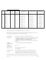
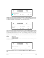
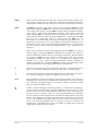
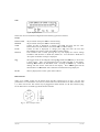
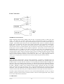
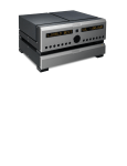
SERIES 3000
THERMOMETER
OPERATING
INSTRUCTIONS
3000.doc
1
Iss. 2/00
SERIES 3000 THERMOMETER
OPERATING INSTRUCTIONS
SOFTWARE VERSION 6.1
Supplied Accessories
1 Mains Cord
1 Operating Instructions (English)
When unpacked, inspect for physical damage and report any defects immediately in writing, retaining
packaging materials for inspection. Before placing into service, ensure mains voltage is correct.
Instruments are normally supplied for 240Volts 50Hz. Other voltages may also be selected according
to the chart in the Maintenance section. Be sure to also change the fuse to the correct type and rating.
SAFETY
This apparatus is designated Safety class 1 as defined in the IEC publication 1010-1 (Amend 1).
CE MARKING
This apparatus complies with the CE marking directive, 93/68/EEC, and is in compliance with the
following standards:
Generic Emission Standard
Conducted Emissions
Radiated Emissions
EN5081-1
EN55022 Class B
EN55022 Class B
Generic Immunity Standard
Conducted Immunity (Power Lines)
Conducted Immunity (Signal Lines)
Radiated Immunity
Electrostatic Discharge Immunity
EN5082-1
prEN60 1000-4-4 1kV
prEN60 1000-4-4 500V
prEN60 1000-4-3 3V/m
prEN60 1000-4-2 8kV
Electrical Safety Standard
IEC1010-1 (Amend 1)
INSTALLATION
The Series 3000 Thermometers are designed to be either free bench-standing, or for rack-mounting. If
rack-mounting is required, then the mounting kit should be ordered and the instruction supplied with
the kit should be followed. The 3000 series are ½19", 2.5U high.
When connected to a mains supply, the mains cord provided with the equipment should be used, and
connected only to a mains supply with a suitable earth connection. Before connection to the mains
supply ensure that the correct voltage is set, and the fuse is of the correct rating
3000.doc
2
Iss. 2/00
MAINTENANCE
Normally no maintenance is required other than cleaning with a moist cloth.
detergents or solvents.
Avoid aggressive
CAUTION:
Before any maintenance, repair or exchange of parts or fuses, the instrument must be
disconnected from the mains supply and all other power sources. In the event of a fault occurring, the
instrument should be returned to our factory or Agent for rectification. A mains fuse is fitted to the
mains inlet socket on the rear panel, and should be replaced if necessary. The Instrument should only
be serviced/repaired by a competent engineer and only design approved replacement parts used.
CAUTION:
Disconnect the mains lead and all connecting leads, before removing the fuse holder.
Replace only with the correct fuse type, i.e. according to the following chart.
LINE
VOLTAGE
Selection
Range
Vac
47-63Hz
Fuse (250V)
IEC 127
5 x 20 mm
100V
120V
220V
240V
90-110V}
108-132V}
198-244V}
216-264V}
630mA (T)
315mA (T)
Maximum Input Power: 25VA
BATTERIES
The thermometers may be used either directly connected to the mains supply or for portable
applications run from the internal batteries. Approximately 8 hours continuous operation from a full
charge is possible. The battery charger is built into the instrument and charging commences
immediately the mains supply is connected, Illuminating the LINE LED on the front panel. The
batteries used are of the sealed lead acid type; continuous trickle charging causes no harm to the
batteries and we always recommend running from the mains supply when possible, thus ensuring the
batteries are always fully charged and ready for portable applications. The charger will automatically
switch to trickle charge or fast charge mode depending upon the battery state.
LOW BATTERY indication is displayed when the batteries have approximately 10% charge left.
When this indication appears, the thermometers should be connected to a mains supply as soon as
convenient, as approximately 50 minutes operating time remains. To extend the battery life, the
backlight can be turned off via the OPT menu. Operating time without backlight is approximately 14
hours.
3000.doc
3
Iss. 2/00
TECHNICAL SPECIFICATION
DISPLAY:
LCD Graphics Panel, 240 x 64 dot, with LED backlight contrast control via
front panel keyboard.
INPUTS:
2 channels for PRTs via 6 pin Lemo sockets. LEMO type number for input
plug: FGG1B.306.CLAD52
IMPUT IMPEDENCE > 10MΩ
Max. input Voltage ± 40Vdc, 28Vrms
Common Mode Rejection 50Vrms
The inputs are linearised and user selectable to the following standards:IEC751 R0=100Ohm, Ra=3850
US/JIS R0=100 Ohm,Ra=3851
EN-751 R0=100 Ohm, Ra=3850 in accordance with ITS90 standards
USER Up to 20 probes may be configured to customer entered constant, A
B, C, and R0 values.
A Standby current is always passed through the sensors.
UNCERTAINTY OF MEASUREMENT:
INPUT
Pt100
RANGE
°C
-200 … -100
-100 … +500
+500 … +800
RESISTANCE
Ohm
18 … 60
60 … 280
280 … 450
CURRENT
1mA
1mA
1mA
RESOLUTION
°C °F K
0.001
0.001
0.001
UNCERTAINTY
1 year @ 20 ±5°C
0.02°C
0.01°C
0.02°C
2 channels for thermocouples (Model 3001) via 4mm sockets. A range of
thermocouple plugs with binding posts is available as accessories , see price
list.
The Inputs are linearised for the following thermocouple Types
B,E,J,K,N,R,S,T and in accordance with the following Standard, NIST 175,
ITS 90. Types C & D to ASTM E988
Reference Junction compensation may be selected for the following modes:Automatic:- Internal Reference Junction range 0 to +40°C
External:- Via Pt100 sensor connected to channel A or B range 0 to
+100°C
OFF:Turns the Reference Junction OFF = 0°C
3000.doc
4
Iss. 2/00
UNCERTAINTY OF MEASUREMENT
TYPE
B
C
D
E
J
K
N
R
S
T
RANGE
°C
+250
+1820
0
+2315
0
+2315
-200
+1000
-210
+1200
-200
+1372
-200
+1300
-50
+1768
-50
+1768
-200
400
DISPLAY
RESOLUTI
ON µV
to
RESOLUTI
ON
°C °F or
K
0.01
to
0.01
1.0
to
0.01
1.0
to
0.01
1.0
to
0.01
1.0
to
0.01
1.0
to
0.01
1.0
to
0.01
1.0
to
0.01
1.0
to+
0.01
1.0
1.0
UNCERTAINTY
@ 20°C ± 5°C 1 YEAR
± (0.025% Rdg +
0.006%FS) *
± (0.075% Rdg +
0.005%FS)
± (0.075% Rdg +
0.005%FS)
± (0.026% Rdg +
0.004%FS)
± (0.03% Rdg +
0.005%FS)
± (0.035% Rdg +
0.006%FS)
± (0.035% Rdg +
0.005%FS)
± (0.02% Rdg +
0.015%FS)
± (0.02% Rdg +
0.015%FS)
± (0.025% Rdg +
0.015%FS)
UNCERTAINTY
@ 20% ± 5°C 60 Days
TEMPERATURE
COEFFICIENT
/°C
± (0.02% Rdg +
0.006% FS) *
± (0.05% Rdg +
0.005% FS)
± (0.05% Rdg +
0.005% FS)
± (0.01% Rdg +
0.004% FS)
± (0.008% Rdg +
0.005% FS)
± (0.01% Rdg +
0.006% FS)
± (0.01% Rdg +
0.005% FS)
± (0.005% Rdg +
0.015% FS)
± (0.005% Rdg +
0.015% FS)
± (0.005% Rdg +
0.015% FS)
7 ppm Rdg +
ppm FS
7 ppm Rdg +
ppm FS
7 ppm Rdg +
ppm FS
7 ppm Rdg +
ppm FS
7 ppm Rdg +
ppm FS
7 ppm Rdg +
ppm FS
7 ppm Rdg +
ppm FS
7 ppm Rdg +
ppm FS
7 ppm Rdg +
ppm FS
7 ppm Rdg +
ppm FS
* Apply to readings above 600°C
The above figures apply to values with Reference Junction switched off.
Reference Junction uncertainty when used in automatic mode (INT) is better than 0.3°C at + 20°C
with a deviation of typically 0.03°C/°C over the range 0 to 100°C.
CALIBRATION:
Digital security code protected. Default number set 9252
BATTERIES:
1 x Sealed Lead Acid Battery 6V 2.8AH to power digital circuit and display
1 x Sealed Lead acid Battery 6V 1.2 AH to power analogue circuit
1 x Lithium Battery T068AA for data logging memory
Operating time after full charge 8 hours with backlight, 14 hours without
backlight
WORKING
TEMPERATURE:
0…50°C rel. humidity less than 90% non condensing
STORAGE
TEMPERATURE:
-20…+55°C
MAINS SUPPLY:
100/120/220/240 Volts +10% -13%
47…63Hz. 80VA
DATA LOGGING:
Up to 4000 single channel values may be stored with date and time.
MATHS:
Computes Max/Min values, Mean values, peak to Peak values, and
standard deviation. Values all computed from values stored in log.
ANALOGUE OUTPUT: This is a factory fitted option comprising of a single BNC socket fitted to
3000.doc
5
Iss. 2/00
6
6
6
6
6
6
6
6
6
6
(OPTION)
3000.doc
the rear panel. The output is scaled 1mV/°C. a 12 bit D/A converter is
used and the resolution is 0.1°C. The output refers to the value on the
display. Accuracy ± (0.5% Rdg + 0.5%FS)
This option is designed primarily for following trends and is not intended to
be used when accurate measurements are required.
6
Iss. 2/00
GENERAL
The series 3000 Thermometers come ready for immediate use, with rechargeable batteries and built-in
charger.
The instruments are switched on and off using the left hand buttons marked appropriately. Connecting
the mains cord automatically enables the battery charging circuit and charges the batteries at the
required rate. The LED marked "LINE" will illuminate to show that mains power has been connected
to the thermometer and the LED marked "FAST" will light when the batteries are low and the charger
is charging at a high rate. The charger will automatically reduce the charging current to a trickle
charge as the batteries reach approximately 80% of full capacity. Continuous trickle charging will not
affect the batteries and we recommend that the Series 3000 Thermometers are used with the mains
supply connected whenever possible.
To measure temperature, a suitable probe should be connected to input A or B. The measured
temperature will be displayed in large units and the actual resistance or voltage measured will be
displayed in smaller units below, together with the measuring current mode selected. In addition the
probe configuration and channel details will be displayed along the top of the display.
fig .1 Typical display
FRONT PANEL KEYS
Fig. 2 : Front Panel Keyboard
3000.doc
7
Iss. 2/00
DISPLAY CONTRAST: To change this display contrast, press and hold down either the ↑ or ↓ key
the contrast will vary and may be selected for optimum viewing. The contrast and the viewing angle is
changed and it may be desirable to alter the contrast from time to time as your reading position alters.
A
selects channel A to the display
B
Selects channel B to the display
A-B
Displays the difference between probe A and probe B
in this case the millivolt/resistance reading will not be shown.
Fig.3: Display in A-B Mode
SENS
A menu is displayed giving the choice of probe configurations, For the model 3002 there are
3 standards to choose from. IEC751, US/JIS, EN-751 in addition there is a fourth option Usr
which allows the operator to store probe characteristics under a file number, up to 20 different
probe characteristics may be stored. NOTE The status line at the top of the display will
confirm the current sensor configuration. To change sensor configuration press SENS key and
from the menu displayed select the option required by pressing the button immediately below.
If the Usr (user) key is pressed a further menu will be displayed, the probe characteristics can
then be entered together with a probe number. A maximum of 20 different probes may be
stored in this way.
Fig. 4:Probe configuration menu
For the model 3001 the menu first offers a choice of Prt’s or thermocouples, if Prt’s are chosen than
the menus are as above. With thermocouples selected a menu will offer a choice of thermocouple
types, press the key below your chosen type to select it. The choice of reference junction configuration
will then be offered AUTO or EXT, the most commonly used option is AUTO which selects the
internal reference. It should be noted that there is a separate reference for each channel and that every
effort has been made to ensure that the best possible performance for the reference junction is
achieved. Should an external temperature be used for the reference then the EXT option should be
selected and a Pt100 probe connected to the RTD input and temperature sensed by this probe will be
used as the reference junction temperature. When the OFF option is chosen the Reference Junction is
turned OFF and the values are referenced to 0°C.
AN IMPORTANT feature of the 3001 thermometer is that each channel may be configured with any
sensor type so that RTD’s may be compared against thermocouples.
3000.doc
8
Iss. 2/00
SENSOR CONFIGURATION
The 3002 thermometers offer real flexibility, with 3 standard Pt100 linearisations plus a user
option. These options may be selected as follows.
Press key SENS and menu will display the options:
IEC751: Linearises in accordance with IEC751 tables with Ro=100ohm & Ra=3850
US/JIS: Linearises in accordance with US and JIS tables Ro=100ohm & Ra=3916
EN-751: Linearises in accordance with ITS90 Standards Ro=100ohm & Ra=3851
Usr Enables probe specific coefficients to be programmed and stored and recalled with probe
identification serial number. The top line of the display shows the configuration of the probe
selected, it is permitted to set channels A & B to different configurations. The information is
displayed as follows:
Channel identification
Standard selected
(If A-B is displayed then this status line blanks)
Ro
Ra
3 or 4 wire.
To change a sensor configuration first select Usr, and enter probe number (1 to 20) and
confirm with OK key. To review/edit the coefficients press the Rev button, the upper half of
the display will shows the probe coefficients Ro, A, B, & C values. The lower half of the
display enables these coefficients to be edited by selecting Yes, each value may now be
changed individually by pressing the key directly below the option required. (e.g. press Ro
and you will be asked to enter the Ro value). Confirm this selection with OK, at this point the
value is not written to the memory and it is possible to return to the previous setting. Once all
the coefficients have been edited press OK you will then be asked if these new
coefficients should be stored in the memory, press No and you will exit the edit menu without
storing the new values. Press Yes and the new coefficients will be stored . Press Quit to return
to the measuring screen.
Fig.5: Review menu for probe characteristics
UNIT
Fig.6: Edit menu for probe characteristics
This key changes the units of the temperature display, each key press will change the units to
the next available in the order °C °F K
RESN When the thermometer first powers up the display defaults to a resolution of 0.01, this
resolution can be increased to 0.001 by pressing the RESN key, pressing again returns the
resolution to 0.01
MATH This takes you into the maths function of the thermometer and allows statistical analysis of
stored values to be displayed. (use the Log function to store these values) Press Stats and the
following values will be displayed, Max and Min values, Mean value, Peak to peak value,
and Standard deviation. The number of samples these values are derived from is also
displayed.
Fig 8. Stats Menu
3000.doc
Fig.7 Display of statistics
9
Iss. 2/00
WARNING: STATS will only be calculated and displayed from values held in the log, and
will only be displayed when the stored log values are all for the same channel. If different
channel readings have been stored the STATS is invalid . It is also important to be aware that
changing the probe characteristics settings during logging will invalidate any STATS
displayed.
A minimum of 2 readings in this log is required to complete the STATS.
MEM
This key will take you into a menu with the options Cal or Log. The Cal option takes you
into the instrument calibration routine and the Log into the data logging function.
fig.8: Mem menu
SCAN..DATALOG FUNCTIONS
To set a scan sequence and store values in the datalog enter SCAN option the display will read
A0
Pt100
+
EN60741
R0 = 100.000
100.000
a = 3851 4wre
°C
------------------------------------------------------------------------------Scanner is : off
Memory is : off
Scan
Timer
Mem
Quit
Select Scan from the menu to set up the scan sequence
A0
Pt100
+
EN60741
R0 = 100.000
100.000
a = 3851 4wre
°C
------------------------------------------------------------------------------Scanning list is : off
SL1
Quit
SL2
OK
SL3
SL4
Edt
Off
Four different scanning lists labeled SL1 to SL4 may be set up to be stored and recalled for later use,
Select the list to be edited using the Edt key
3000.doc
10
Iss. 2/00
A0
Pt100
+
EN60741
R0 = 100.000
100.000
a = 3851 4wre
°C
------------------------------------------------------------------------------Scanning list edit: SL1
A0
B0
<
>
Add
Del
Quit
OK
The channels available to add to the scanning list are designated A0 and B0 (A0…A4 , B0…B4 if the
extended scanner option is fitted). The Flashing channel may be added with Add key or deleted with
the Del key moving between the channels with the < > keys. Once a channel is added to the scan list
the channel is highlighted, pressing the OK key stores that scanning sequence.
A0
Pt100
+
EN60741
R0 = 100.000
100.000
a = 3851 4wre
°C
------------------------------------------------------------------------------Cyc = Cont
00:00:00
<
>`
Delay = 00:00:00
Rate =
Clear
Quit
Edit
OK
To set the number of scan cycles and the delay between cycles select the Timer and the above menus
will be displayed. The changeable parameters will flash. To change the flashing parameter press Edit
and enter the appropriate number of Cycles 0 to 9999 or continuous. Pressing the Clear key returns to
the default setting. The following may be set Cyc - This is the number of scanning cycles any number
between 1 and 9999, continuous can also be set. NOTE if the data logger is turned on then the number
scan cycles is limit to 4000 readings. Delay - This sets the delay before the scanner cycle starts and
may be set between 00:00:00 and 59:59:59. Rate - This sets the time between each channel selection
and may be set between 00:00:00 and 59:59:59.
Example:
Set Cyc to 10
Set Delay to 00:10:00
Set Rate to 00:00:40
The channels will be scanned 10 times with a start delay of 10 minutes and 40 seconds delay between
each channel selection.
A0
Pt100
+
EN60741
R0 = 100.000
100.000
Input =138.500 Ohm
Hold
a = 3851 4wre
°C
+I
Busy
SL1
0/10
The measurement display will start in the measurement Hold position Press TRIG to start the scan
cycle.
3000.doc
11
Iss. 2/00
A0
Pt100
+
EN60741
R0 = 100.000
100.000
Input =138.500 Ohm
Run
a = 3851 4wre
°C
+I
Busy
SL1
0/10
The display will first show the count down timer once the start time is reach the display will indicate
run and the number of scans will be display. Once the set number of scans has completed the display
will return to the Hold position until triggered again.
DATA LOGGING SETUP
To store values enter the MEM option and select Log select the Set Up option and the number of
samples or readings to be stored will be displayed. To accept this number press Yes, to change the
number press No, and then enter the number of samples you wish to store, (this number must be
between 1 and 4000.) Press OK, you will then be asked to confirm your choice. Press Yes, the
logging mode can switched on or off and the previous stored values scrolled to the display using the
Rev option. The values will be displayed with log number, channel measured, the temperature value,
date and time.
Fig.9 : Data logging Menu
Fig.10: Screen showing logged values
To scroll the pages use the left hand up/down arrow keys, and to exit the review screen press the
OK/MEM key.
To clear the current logged values select New and the display will ask you to confirm that you wish to
clear the current stored values. Press Yes or No. If Yes is pressed you will be requested to confirm
your choice, press Yes to confirm. The logging mode may then be activated by pressing the On key.
When the set-up is complete press Quit and return to the measurement mode. The bottom line of the
display will show the data log status information:“Hold Samples = 0/20 ”
To trigger the measurements and store samples press the TRIG key. This line will now change to
“Run Sample=#/20”, where # = the number of samples stored. When the set number of values are
stored, the measurements return to the Hold state. Press the TRIG key again and the display will ask if
you wish to clear the current log. Press Yes and confirm, the TRIG key will now start a new measure
and store cycle.
The values logged will always relate to the channel on the display. It is possible to stop the logging
function, change channels and restart logging using the TRIG key (see TRIG section below).
3000.doc
12
Iss. 2/00
ZERO
This key zeros the displayed value and "Zero" appears in the bottom left hand corner
of the display. NOTE: The Zero offset will be cancelled if the measuring channel is
changed, if the calibration menu is entered, or if the sensor configuration is changed.
TRIG
The TRIG key operates in two modes. These may be set using the OPT menu. The
default mode enables the TRIG key to be used as a run/hold button and Run appears
on the display above the key, pressing TRIG holds the display and Hold will appear
on the display. It will also be noticed that the flashing "Busy" blanks in the hold
mode. Pressing TRIG a second time returns the instrument to the run mode. The
second mode of operation may be set using the OPT menu. This enables the TRIG
key to be set in single shot mode, i.e. when pressing the TRIG key, one
measurement is made and held on the display, and the busy sign flashes once. It
should also be noted that even for large changes in temperature readings the new
measurement will be valid, the specially designed measurement circuit ensures that
the A/D converter is fully zeroed and stabilised before a new measurement is
displayed.
When used in conjunction with the data logging function the TRIG key is used to
start the logging. Pressing the TRIG key again puts the instrument into a hold state
and the measurement channels may now be changed. Restarting the measurement
by pressing the TRIG key also resumes the data logging; the newly selected
measurement channel now being stored. It is possible to store readings from
channels A, B, or A-B. When in single measurement mode the instrument is
normally in the hold state. Pressing the TRIG key initiates one measurement which
will be stored in the log , the instrument then returns to the hold state.
+I
This selects the measuring current in the positive direction. The measuring time is
approx. 1.8 seconds per reading for channels A and B, and 3.6 seconds for A-B.
-I
This selects the measuring current in the negative direction. Measuring time approx.
1.8 seconds per reading for channels A and B and 3.6 seconds for A-B.
AVE
This automatically switches the measuring current from forward to reverse direction
and displays the average of the 2 readings thus eliminating any errors due to thermal
emf. Measuring time approximately 3.6 seconds per reading for channels A and B
and 7.2 seconds per reading for A-B
√2
Current is reduced through the measuring probes by √2 (half power) enabling any
probe self heating to be determined. The best method of use for this option is to first
allow the sensor to reach a steady temperature and note the value, it will take some
time for the sensor to stabilise. Select √2 current and immediately press the ZERO
key, the reduced current through the probe will reduce the heating effect on the probe
and any value displayed will represent the temperature change due to the reduced
current. The advantages of using the ZERO key in this way are twofold, firstly, any
errors in the measuring amplifiers due to a change in current are removed, and
secondly from a calculation point of view, the change in reading will be displayed
without further calibration being required.
3000.doc
13
Iss. 2/00
OPT
Fig.11: Options menu
Selects the various instrument configurations the following options are offered:
Set-up:
BACKLIGHT
BEEPER
TIME
DATE
REM I/F
may be turned on/off press OK to confirm setting.
may be turned on/off press OK to confirm setting.
Current set time is displayed, to change press Chg and enter the new time.
Hours/minutes/seconds format is used. Press OK to confirm settings.
Current set date is displayed, to change press Chg and enter the new date
Days/Month/year format is used. Press OK to confirm settings.
If an interface card is fitted, pressing this key will display the various settings
available to that interface i.e. Baud rates, address etc. If no interface is fitted then a
“No Option Available“ message is displayed.
Trg:
The trigger mode can be changed, selecting Sng enables the TRIG key to be used as
a single trigger. Only one measurement will be made and held on the display.
Selecting Run enables the Run/Hold mode. Pressing the TRIG key holds the
reading with the current value held on the display. Press TRIG again and the
measurement is in Run mode with continuous measurements being displayed.
SCAN
This key displays the scanner option menu if fitted.
RTD INPUTS
There are 2 LEMO sockets for the Pt100 inputs and the connections are as fig 1. For the best
performance we recommend 4 wire sensors, but the 3000 series thermometers are able to measure with
2, 3, and 4 wire sensors. The sensors may be plugged into either channel A or B. The connection plug
for the PRT sensors is LEMO type FGG.1B.306.CLAD52
Fig.11: View of input socket
3000.doc
14
Iss. 2/00
Probe Connection
THERMOCOUPLE INPUTS
When measuring thermocouples (Models 3000 & 3001) care should be taken to achieve the best
results. The inputs are via 4mm sockets and a range of thermocouple plugs are available for
connection. The input sockets are copper and behind the front panel to avoid the external effects of
draughts. The reference junction may be set in three different modes, the first is automatic (INT) and
Pt100 sensors are attached to the upper input sockets and monitor their temperature automatically
applying the corrections. The accuracy of the internal reference is approximately ±0.3°C to achieve
more accurate results, an external reference may be used (Ext), when using an external reference the
Pt100 input is used to sense the external reference temperature. The accuracy of this is as for Pt100
measurement ±0.01°C in addition to this there will be some errors due to the configuration of the
external reference, but generally with care, it is possible to achieve better results when using the
external reference mode. Finally, the reference junction may be switched off (OFF) and in this mode
the thermometer assumes a reference junction temperature of 0°C. This mode of operation is used
when an external automatic reference is used such as our RJ## series. Again using this mode of
operation gives slightly better results than will be achieved when using the internal reference.
CAUTION
When measuring thermocouples with the 3000 thermometer it should be remembered that the
temperature may be read to 0.01°C and this is equivalent to approximately 0.4µV per digit with a type
K thermocouple. Care must therefore be taken to avoid exposing the instrument inputs to draughts or a
heat source such as sun shining on the front panel. To obtain the best results the instrument should be
placed in a temperature controlled room and switched on for at least half an hour before measurements
are made. Running on battery power without the mains supply connected will also be of benefit.
When connected to the mains the batteries will be charged and additional heat generated inside the
instrument. Great care should also be taken to ensure that the correct materials are used when making
connections and avoid unnecessary joints of different materials as these again will cause small errors.
We offer a range of thermocouple connectors for use with the 3000 thermometer as well as a range of
automatic reference junctions and an external reference enclosure with integral Pt100 sensor, please
ask our sales staff for more information.
CALIBRATION
3000.doc
15
Iss. 2/00
The 3000 series of precision thermometers has been designed to give long service and permanence of
calibration together with a low cost of ownership. Attention to detail in the design stage has produced
an instrument that is quick and simple to recalibrate with the minimum of equipment . Prior to
calibration the unit should be placed in a temperature controlled environment for a minimum of 4
hours, care could be taken to use good quality test leads, thus avoiding any thermal emf, together with
resistance standards of known value. To select the Cal option press the MEM key and then select the
Cal option from the menu. The calibration counter number will be displayed, a second menu choice
will be given Cal or Prt. The Prt option will print the calibration constants to the screen, this is used
as a diagnostic tool to ensure that there is no corruption of these constants. Select the Cal option and
you now enter the calibration routine. The display will ask for a passcode to be entered, the default
passcode number is 9252, enter this number and press OK. Any number between 0 and 9999 is valid.
The display will then give you the option of changing the passcode to your own personal number, if
you select Yes you will then be asked to enter your chosen number via the keypad ending by pressing
OK. You will then be asked to confirm your number. Once the new number is accepted the calibration
counter will increment 1. The display will then give a choice of calibration RTD, T/C, RJA, RJB, it is
preferable to calibrate the RTD ranges first.
RTD CALIBRATION
Select this option by pressing the key below RTD, the display will then prompt you to connect 100
ohm resistance standard to channel A. When connected press OK and you will be prompted to enter
the exact value of the standard. Once the value is entered and the OK pressed you will be asked to
confirm the value by pressing OK again. The instrument will then calibrate itself against this standard
storing the calibration constants in the memory. Next you will be asked to connect a 400 ohm
resistance standard and repeat the above. Finally you will by prompted to connect a 250 ohm
resistance standard and again repeat the above. Once this calibration is completed the display will
return to the main calibration menu. At this point you have the option of calibrating the thermocouple
range or pressing QUIT key to return to the measuring mode.
THERMOCOUPLE CALIBRATION
Select this option by pressing the T/C key in the calibration menu. Connect a mV source to the
thermocouple input of channel A using low thermal copper leads and connectors. The display will
prompt you to set the input to 0mVdc and press OK. Next +75mVdc should be supplied and OK
pressed, finally -75mVdc should be supplied and again the OK pressed. These three values will
calibrate the complete thermocouple range of the instrument. The display will again return to the main
calibration screen and the reference junction should now be calibrated.
RJ CALIBRATION
The reference junction of both channel A and channel B should be calibrated. Select RJA, insert a
Pt100 standard thermometer in the 4mm negative (lower) input socket of channel A and allow the
temperature to stabilise, it is necessary to use a sensor that fits securely into this socket. Once the
temperature of the socket has stabilised and a steady temperature reading is obtained, enter the
temperature into the instrument, the screen will prompt you to enter the block temperature. Confirm
the value and press OK. Repeat this procedure for channel B moving the sensor to the negative input
socket in channel B.
Once both channels have been calibrated you may exit the calibration menu with the QUIT key.
3000.doc
16
Iss. 2/00
EQUIPMENT NEEDED
1 Resistance Standard Type RS3/100 Value 100 Ohms
1 mV source -75 … 0 … +75 mV
1 Resistance Standard Type RS3/250 Value 250 Ohms 1 Pt100 sensor and measuring instrument
1 Resistance Standard Type RS3/400 Value 400 Ohms
1 Calibration Lead Type TS01
The Value of the resistance standards should be known with an uncertainty ±5ppm or better
Suitable resistance standards are available for calibration together with a calibration connection lead,
please consult our sales staff.
ENVIRONMENT
We expect the 3000 series thermometers to give long and trouble free service but, as with everything,
there will come a time when you wish to replace it . CROPICO will continue to develop new
instruments and to update the design of existing models , and therefore will be able to offer an
instrument suitable for your needs.
When disposing of the batteries care should be taken to comply with current legislation concerning
their disposal. If in doubt the batteries can be returned to our factory for safe disposal. In addition to
the 2 sealed lead acid batteries there is also 1 nickel cadmium battery which supports the logging
memory.
WARNING
3000.doc
DO NOT DISPOSE OF BATTERIES IN FIRE
DO NOT SHORT CIRUIT
DO NOT PUNCTURE, OPEN, DISMANTLE OR OTHERWISE
MECHANICALLY INTERFERE WITH THE BATTERIES.
DO NOT SWALLOW
17
Iss. 2/00
Additional Products From Cropico
DIGITAL OHMMETERS
RESISTANCE BRIDGES
RESISTANCE DECADE BOXES
RESISTANCE STANDARDS
DIGITAL THERMOMETERS
THERMOCOUPLE SIMULATORS
THERMOCOUPLE REFERENCE JUNCTIONS
THERMOCOUPLE SELECTOR SWITCHES
PT100 SIMULATORS
PRECISION WATTMETERS
INSULATION TEST SETS
UNIVERSAL CALIBRATORS
POWER ANALYSERS
HIPOT TESTERS
ELECTRICAL SAFETY TESTERS
Phone, fax or e-mail for further information on the above or for a copy of our
general catalogue:- Phone:- 020 8684 4025
Fax:020 8684 4094
E-mail:- [email protected]
Website:- www.cropico.com
3000.doc
18
Iss. 2/00