1
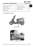
KIRON 80-200 f/4 #25132275
A supplement to the service manual in Kiron Klub files – by Mel Smith, August 2011
The construction of this lens differs greatly from the KIRON 80-200 f/4.5 zoom lock #26409228 although both were made
in 1982 according to the serial number. (First digit.) They are different types, (second two digits) being a 64 and a 51.
The subject lens, a 51, is f/4.0 and does not have either zoom lock or focus stop and, unlike the 4.5, the filter does rotate.
The lens was an Ebay “for parts” purchase correctly described as having an
aperture stuck wide open and pictured as having “haze or fungus” with a photo
much like Figure 1.
These colors suggest birefringence from a film of oil or grease. The front of a
zoom lens often is near a heavily-greased helix and I am of the opinion that
when stored front-down in hot weather that helix lube may flow to the glass.
The seller was correct. The aperture was stuck wide open.
He did not mention and may well not have known that the stop-down button on
the side of the Olympus OM mount was pushed in when normally a spring has
it out.
The glass at the rear was clean and not scratched although very near the rear of
the lens. A rear lens cap should be used on this lens when off-camera. The
body showed few signs of wear or use.
Figure 1
IMPORTANT: If possible, check to see if your lens zoomed to 200mm makes a sharp image of a distant scene when
focus is set at infinity.
DISCLAIMER AND SOME ADVICE:
I am being altruistic, but follow these instructions at your own risk. I do not guarantee that there are no errors of omission,
commission, opinion, typos, or your interpretation. Changes during manufacture may make your lens different in some
ways.
It is assumed that all small pieces and screws are put in a safe place with instructions for their replacement as found.
Replacement parts may not be available.
Use proper tools to avoid damage to parts.
Do not rotate something newly released by removal of something else without knowing what you are doing.
It is best to read the instructions a couple of times before applying tools to the lens.
Do not take something apart just because you think it can be done--have a reason.
If you repair only the needed you cannot guarantee the rest, but it is easiest
If possible, check the infinity focus of the lens before working on it.
WHY A PHILLIPS SCREWDRIVER DAMAGES JIS SCREWS.
At the factory, the Prime Directive for installation of cross-point screws, both JIS and Phillips, appears to be that removal
will never be needed. At a glance JIS and Phillips appear the same, but certainly are not so.
A JIS (Japanese Industrial Standard) cross point screw is made with slots that have vertical faces that take the force of the
vertical faces of a JIS screwdriver. The torque force of a JIS screwdriver on a JIS screw is evenly distributed on the metal
from top to bottom of the slots.
Unlike JIS, the slots of a Phillips screw are tapered from top to bottom on the faces that take the torque force. A Phillips
screwdriver is tapered to fit and torque force is evenly distributed from top to bottom of the slots in the screw.
When a Phillips screwdriver is applied to a JIS screw the tapered screwdriver faces put torque force only on the top of the
slots in the JIS screw. With sufficient force the metal deforms and this weakens the metal so that added force makes more
deformation until the slots merge into one tapered hole.
The design of the JIS screw makes installation with great force possible, and in addition thread locker often is used. Often
the thread locker is like Pliabond contact cement. Methyl Ethyl Ketone or acetone or heat (red hot tip of soldering gun for
30 seconds only if all is metal) will soften it but the screw may still be very tight. Use a steady force as the gooy stuff
slowly yields. A jerk my break things. The thread locker is strong as ever when cool or when the solvent evaporates.
As force is applied with a Phillips screwdriver to a Phillips screw head the taper causes a force that lifts the screwdriver up
out of the slots. This is a cam action and the screwdriver is said to “cam out”. Downward pressure keeps it in for
installation of a screw. Downward pressure is needed to turn the screw out and that is a force to keep the screw in. Phillips
screws are not designed for removal.
For automatic assembly machines the Phillips screw has an advantage. The machine can be set so the screwdriver cams out
before damaging the screw.
NAMES OF THINGS–and some hints:
Ring: Any hollow cylinder or sleeve regardless of wall thickness or length relative to diameter. (Read that again. It is not
the normal definition of "ring")
Index Ring: The ring with the focal lengths and the distance reference line on it.
Aperture Set Ring: This is the ring the photographer uses to set the aperture.
Slot: All the way through. No top or bottom. Some are cams, some are guides. See channel.
Channel: Not all the way through. A ditch or trench.
Shaft: An axle. Something rolls on it.
Screw-shaft: A shaft with screw head and threaded on far end. Service manuals may call it a shaft.
White ring: A plastic (probably Delrin) ring, a roller or slider. It rides on a screw-shaft and in a slot or channel.
Element: A single piece of glass.
Group: Two or more elements. They may be cemented face to face and appear as one element.
Lens group: My amateur repair viewpoint is elements held together in a sealed unit. The position of elements/ within the
lens group may be critical and disassembly of lens groups is best avoided because proper reassembly may require special
equipment to maintain the optical characteristics. By this criterion this Kiron 80-200 lens has 4 groups, but to an optical
engineer it has 12 elements in 8 groups.
Focus Group: Usually, the lens group at the front of the lens. This one is a cemented doublet plus a single element.
Helicoid: (helix) A multiple threaded spiral used for focusing. If the filter thread ring rotates as the lens is focused you
have a simple one with multi-threaded male threads into female threads. Be sure to scratch the exact point of separation
because any other will mess up the focus. If the filter thread ring does not rotate you have a more complex arrangement,
usually with guide plates but this one has no guide plates! Both kinds are major sources of problems for amateurs.
Distance Scale Ring: The ring with the distance scale on it.
JIS screw: A screw with Japanese Industrial Standard cross point head. Usually the screw goes through a bare hole and
into a threaded hole and holds these together.
Set screw: (grub screw) A screw with a point on the end. They go into a threaded hole and the point digs into something to
hold an adjustment in place. Set screws often are very small and short with a slot-head hidden with black paint. (Black
fingernail polish). They need not be extremely tight for that sharp point to do its job so thread locker commonly is used to
hold them in place. Since they are small the screwdriver has little leverage on the thread locker and they are hard to
remove. Grind a screwdriver blade to be an exact fit to the slot top to bottom and side to side to avoid breaking off one
side of the slot. MEK or acetone and a sharp pin can be used to remove the black paint, but the solvent is slow to go down
the threads and soften the thread locker. Only if all is metal, hold a red hot soldering gun on the screw for 30 seconds to
soften the thread locker then immediately apply the screwdriver before it cools and hardens. If the wall of the ring they are
in is thick enough they need not be removed completely. If you leave them in place, be sure they are secure.
If there are several set screws around a ring, tighten them evenly to avoid binding.
A thin piece of foam with a hole in the end is a good holder for replacing a set screw.
FOCUS GROUP REMOVAL: (failed)
In the Kiron Klub files is a service manual with many parts diagrams for different
lens mounts. On the last pages are some step by step instructions. This manual
was of considerable help.
Oil from the nearby helical focusing threads was on the back side of the front
(focusing) group as shown in Figure 1. A logical approach is removal of the front
focus group for cleaning the back-side. However, if your lens has been assembled
as securely as mine was you will not be able to follow the instructions given in the
service manual, which are: "Remove the set screw (2) on the front ring (1) and
separate the Front Ring from the Front Doublet (501) and the Third Lens
Element Assembly (502)"
Figure 2
The upper yellow arrow in Figure 2 points to set screw (2) at the rear edge of the
front ring (1) shown in red. There are three of them. The other yellow arrow
points to one of three set screws at the front end of ring (7) in green.
Figure 3 is a cut away diagram of the front of the lens. It shows a cemented
doublet under the front ring (1) in red. Under the front of ring (7) is a single
element which in combination with the doublet makes the front focusing group.
The oil suggested by Figure 1 may be on the back of this focusing group. The
blue line in Figure 3 shows the helix and oil or grease from the helix may have
migrated to the glass when the lens was stored front-down. (See Fig. 14.)
Figure 3 Focus group
In the service manual neither Figure 3 nor the exploded parts diagram (a portion
shown in Figure 4) clearly show the construction of front ring (1). There is some
suggestion in Figure 3 that the front ring fits over a lip on ring (7) and it may be
that it is held there by threads with copious amounts of thread locker in addition
to set screws. I say this because my efforts failed to remove ring (1) after
removing the set screws (all 6 of them) and applying MEK to the parting line
and the set screw holes. I even made a special glued-on tool that avoided
squeezing the front ring.
Therefore I turned my attention to the rest of the lens hoping that I might reach
the back side of the front focus group after removing the other glass in the lens.
It turned out that instead of removing the other glass I found that the helicoid
could be un-meshed to give access to the rear of the focus group.
To do this, first the diaphragm module and lens mount had to be removed. They
needed repair so that work is next.
Figure 4
SEPARATING THE LENS, REMOVING, AND REPAIRING
THE MOUNT :
Removal of the rubber grip revealed four holes made for access to JIS screws
which were removed. For this, the focus is infinity and the zoom to near the
bottom of the “135" lettering. The red line in Figure 5 leads from one of the
four access holes to the threaded hole for the JIS screw reached through the
access hole. The screw went through a bare hole in the inner helicoid ring that
is out of sight under the distance scale ring in Figure 5.
Figure 5
The lens was focused to infinity as shown by the green line before the screws
were removed.
In Figure 5 the yellow arrow points to one of three JIS screws that hold the
index ring in place. These were removed and the index ring was removed.
The result is Figure 6. The service manual gives #527 as an assembly of prime
lens with diaphragm. In Figure 6 the mount is still attached to the 527
assembly by four large-headed JIS screws in adjustment slots. One is shown
by the red arrow.
Shims are used to position the screws in the adjustment slots. Tiny red dots
mark the ends of an aluminum-colored shim on this lens. In addition there was
a thin brass shim that can be seen only if Figure 6 is sufficiently enlarged.
Yours may be different.
Figure 6
In Figure 6 the red letter “S” marks a slot in the mount housing that goes over a
stud in assembly 527. This positively orients the mount for replacement and it
is not necessary to scratch alignment marks.
The four “red arrow” mount screws were removed with great care because
replacements are not available. Use a proper JIS screwdriver, MEK or a hot
soldering gun to loosen the thread locker. Then the mount can be removed.
The stop-down preview button on the Olympus OM mount was depressed and
not out in the normal fashion. Fiddling with it showed that its action was
rough and sticky. Figure 7 is a close look at the problem. When the button is
depressed it pushes lever “A” in the direction of the red arrow over stationary
metal item “B”. This action is against a straight spring pressing on the brass
knob on lever “A”.
Also the coil spring must be stretched to the set aperture, here being held to
f/22 by my fingers.
Figure 7
A drop of Radio Shack 64-2301A powdered teflon suspended in a synthetic oil
was place on part “B” and then the stop down button worked well, although still requiring considerable pressure. I think
the coil spring is too strong.
DIAPHRAGM SERVICE
Figure 8 shows assembly 527 without the Olympus mount. Exposed glass front and back is protected with Scotch matte
magic tape. The red arrow shows one of the four threaded holes that held the JIS mount screws in adjustment slots. The
yellow arrow shows one of the three threaded holes that held JIS screws that attached the index ring. The green arrow
shows one of four threaded holes for screws that attached the zoom and focus module to assembly 527. In this way, 527
holds everything together except the rubber grip.
The diaphragm assembly is inside assembly 527. In the subject lens it was
stuck wide open. There was no separation at the parting line so I unscrewed
the rear lens group without making any measurements for replacing it. Had
there been a gap, an alignment scratch and a measurement of the gap to
0.1mm would have been made.
After unscrewing the rear lens group I fiddled with the aperture controls and
the diaphragm opened part way as shown in Figure 9. (Sorry, what I do when
fiddling remains unwritten.)
No oil on the blades !!! But of course, being sealed between two lens groups
there is no way lube can reach the blades. Then I looked on the front side
through the remaining glass. Figure 10.
Figure 8 Prime lens and diaphragm
assembly
Where did the oil come from? There is little of it, but enough to retard the
blade action.
The red arrows in Figure 10 point to spanner holes for removing the front
lens element. I found it quite tight and elected to use Coleman brand camp
stove fuel (pure n-heptane) to flush away the oil without removing the front
glass. I poured in, sloshed around, and decanted about two tablespoons of
solvent three times, then allowed the remainder to evaporate.
This cured the stuck aperture.
Green arrows in Figure 10 show JIS screws bedded with some white stuff in
adjustment slots. These may be an adjustment for the size of the aperture and
require specifications of the aperture diameter and/or a special tool to set to
factory specifications. The green dots in Figure 9 show the other ends of
these three screws.
Figure 9
The green arrow in Figure 6 (blue arrow in Figure 10) shows one of three JIS
screws found with heads daubed with red thread locker. I did not remove
them. The red dots in Figure 9 show the other end of these screws. Removal
of these screws might release the diaphragm assembly for removal, or they
might just be a start to taking the assembly apart. If you elect to proceed in
this manner make scratches and take photos so you can put all adjustments
back as found.
THE ZOOM - FOCUS MODULE:
This is the left-side item in Figure 5 above and Figure 11 below.
Since attempts to go in from the front failed, the next objective is reaching
the back side of the front lens group and cleaning away the oil that is on it.
Figure 10 Oil on diaphragm blades.
PAY ATTENTION: I got there and back by being careful but I think there
are ways to goof up is you do something different. I have not investigated
possible departures and may not be of any help if you stray.
Figure 11 is the zoom-focus module with rubber grip
removed. The parts under the rubber I have named
“front grip” and “rear grip” are called “zoom drive ring”
and “distance scale ring” by the service manual in Kiron
Klub files
In Figure 11 the zoom has been compressed to shortest
length and the infinity notch of the inner helicoid has
been turned to the infinity position. This is an Olympus
OM mount and some cameras focus by turning the other
way.
The front lens group is attached to the front of the outer
helicoid which is inside the zoom drive ring (front grip)
and secured to it by screw shafts on either side, one of
which is shown here.
Figure 11
The yellow arrows in Figures 11, 12 and 13 point to set
screws which (with some thread locker glue) hold the
front and rear grips together. The yellow dots in Figure
12 show the v-shaped channel for the points of these set
screws.
MAKE A SCRATCH ON THE PARTING OF THE
FRONT AND REAR GRIPS SO THEY CAN BE
REASSEMBLED AS FOUND.
After the set screws were loosened, not removed, the
lens could be pulled apart as shown in Figure 12. This
moves the zoom to maximum length. DON’T TURN
ANYTHING YET.
Figure 12
The red “A” and “B” (with companions 180 degrees
around) are screw shafts to the rear and front zoom
groups respectively. If the screw shafts were removed
the zoom groups would come out to the right AND
OTHER THINGS MIGHT COME APART. This was not done.
The zoom groups’ glass did not need cleaning.
The green X in Figure 12 is a spring for a friction device to improve
zoom action. There are three of them. They are absent on early
models of this lens.
The red dot in Figure 12 shows the focus stop that limits the
rotation of the rear grip ring. As shown it is at infinity for an
Olympus OM mount. This focus stop limits the focus turning only
if the front and rear grips are secured together. As things are in
Figure 12 the front grip can be turned to un-mesh the outer helicoid
from the inner one. THIS MUST BE DONE WITH GREAT
CARE. FIRST, SCOTCH MATTE TAPE WAS PUT ON THE
EXPOSED INNER HELICOID AS SHOWN IN FIGURE 13.
THEN THE FRONT GRIP CONTAINING THE OUTER
Figure 13
HELICOID WAS ROTATED SLOWLY WITH WIGGLING TO
FEEL FOR HELIX SEPARATION. THE YELLOW DOT ON THE FRONT GRIP MARKS THE SCRATCH MADE TO
ORIENT FRONT AND REAR GRIPS. WITH EACH TWO MILLIMETERS OF ROTATION A PENCIL MARK WAS
MADE ON THE MATTE TAPE OPPOSITE THIS SCRATCH. TWO MILLIMETERS IS NOT UNDULY OFTEN
WHEN YOU NOTE THE DISTANCE BETWEEN STARTING POINTS ON THE INNER HELICOID IN FIGURE 13.
WHEN UN-MESHING OCCURRED A CARBIDE POINT WAS USED TO SCRATCH THROUGH THE PENCIL
MARK ON THE TAPE AND MAKE A SCRATCH ON THE METAL AS SHOWN BY THE YELLOW DOT ON THE
INNER HELICOID.
REMEMBER, THIS WAS DONE WITH THE REAR GRIP AGAINST THE INFINITY STOP, THE NOTCH IN THE
INNER HELICOID (FIGURE 11) AT INFINITY, AND THE ZOOM AT MAXIMUM EXTENSION. BE SURE THE
INNER HELIOID END IS IN THIS CONDITION FOR RE-MESHING THE HELIX. IT MAY NOT BE ESSENTIAL,
BUT IT IS BEST TO LEAVE THE INNER HELICOID END ALONE, DON’T TURN ANYTHING.
CLEANING THE BACK OF THE FRONT LENS
GROUP:
Figure 14 is looking inside the outer helicoid ring after most of
the oil has been cleaned away. The helix actually goes a bit
below the rear surface of the front lens group. There is a little
channel about 2mm deep separating the greasy helix from the
glass. Figure 3 taken from the service manual fails to clearly
show this but does tell that there is a single element behind a
doublet with some space in between. If the process of using
solvent for cleaning oil from the back surface gets a bit of
solvent-oil solution into this space the solvent may evaporate
and leave a hard-to-reach oil deposit. Therefore liquid solvent
must not be dropped on the glass. Instead the cleaning must be
done with solvent on a piece of lens tissue or a cotton swab.
Remember that capillary action may draw solvent with any
dissolved oil through tiny gaps.
Figure 14
This is tricky. If the tissue or swab touches the greasy helix it
must be promptly discarded. Of course the solution to this problem is a curl of paper tucked into that little channel.
Remember cutting paper in Kindergarten? I don’t. We did not have Kindergarten, pre-school, or anything like that.
My choice of solvent is Coleman brand camp stove fuel. It is pure n-heptane and leaves no residue of its own. It is
assumed that the lube on any lens this old will be a petroleum product soluble in n-heptane and not a synthetic. Some
synthetic oils do not dissolve well in n-heptane. Any light “naphtha” that evaporates without a residue could be used.
Alcohols and ketones do not dissolve petroleum oils as well as light hydrocarbons such as n-heptane or “naphtha”.
I fear that washing away the old grease on the helix would carry some of it into the space between the doublet and the
single element, Figure 3, where it could not be removed without taking that front ring off. This means that the source of the
problem remains but if it takes another 29 years (the age of this lens) it makes no difference to me at my age, 83.
ASSEMBLY
After assembly is complete mount the lens on a camera and check infinity focus. If it does not check you have used the
wrong place when re-meshing the helix. No need to take it all apart agin, just separate the front and rear grips and try
another place on the helix. I count 19 wrong ones for only 1 right one and they are only a few millimeters apart. That is
why I am very fussy about marking the exact point of separation.
General; Check all glass surfaces and clean as necessary.
ASSEMBLE THE ZOOM-FOCUS MODULE
1.
Re-mesh the helicoids. Turn them all the way, then back off as needed for step 2.
2.
Push the lens together. Align the scratch across the front and rear grips. Check that the notch on the inner helicoid
ring aligns with the infinity mark on the distance scale. Evenly tighten the four set screws that hold the front and
rear grips together. Make them snug, but not too tight. Do not add thread locker at this time.
3.
Check that the notch on the inside helicoid ring properly moves from stop to stop from infinity to macro on the
scale.
INSTALL THE MOUNT ON THE DIAPHRAGM-PRIME LENS ASSEMBLY:
This is for the Olympus OM mount. Your mount may be different, but the prime directive is “Align everything and don’t
force anything.”
4.
Set the aperture set ring to f/22
5.
Hold the aperture stop-down lever on the back over as far as it will go with your finger and hold it there against
spring pressure.
6.
Align the slot in the mount with the stud on the diaphragm-prime lens assembly. This should also align the
aperture-set levers. Ease the pieces together, if any resistance back off and try again.
7.
When assembled, the aperture should be wide open but stop down to f/22 when the stop down lever is activated.
Change the aperture set ring to other f/numbers and check that the stop down goes to the setting.
8.
Start, but do not tighten, the big head JIS screws in the adjustment slots. Turn each one counter-clockwise until the
threads drop in place, then turn clockwise. Gentle does it, force can cause the steel screw threads to damage the
aluminum threaded hole. Everything should fit nicely because this is a KIRON.
9.
Put a lens cap on the mount, set the unit vertical, and install the shims. Press the mount snug against them, then
tighten those screws in adjustment slots. Then add a small dab of thread locker to the head of each screw.
10.
Install the index ring. The white line aligns with the red dot index for the aperture set ring on this OM.
CONNECT THE TWO PARTS OF THE LENS (DISTANCE RING ACCESS HOLES:)
11.
Be sure the zoom-focus module is at infinity.
12.
Align the white line of the index ring with the infinity mark on the distance scale ring and push until the zoom is
near the bottom of the “135" lettering. Then use a flashlight to see if a screw can be installed through the access
hole in the distance scale ring.
13,
If so, do so. Your need a magnetic JIS screwdriver, or else a bit of what auto mechanics call “dubbing” on a JIS
screwdriver to hold the screw.
14.
This is a KIRON, so after one is in the others should be aligned for easy assembly. On lesser lenses the first one
must be left a little loose for a little “play” for the alignment of the others.
15.
Mount the lens on a camera and check the focus. If OK, apply thread locker where needed and install the rubber
grip.
16.
Take pictures. I wish I had taken before and after photos with the lens to show the effect of my work. Maybe next
time.
%%%%%%%%%%%%%%