1
Troubleshooting Guide
A. Check Power Board Before Removal
While the Power Board is still installed in the freezer,
make the following four preliminary checks at the
Power Board with power applied to the freezer:
1.
2.
Check the AC input by setting the meter to
measure AC volts, applying power, and
measure between terminals L1 and L2. The
voltage should be 208 -- 240 VAC, depending
upon the line voltage to the freezer. If so, go to
the next step. If not, the Power Board is not
receiving line voltage and the problem is
elsewhere (loose/bad power cord/wire, bad
circuit breaker, etc.).
Check the fuse by measuring the AC voltage
across Fuse 1. The voltage should be 0 volts. If
so, go to the next step. If any voltage is read,
fuse is blown, turn the power off and replace
the fuse (051272 SLO BLO
.063A-250V-5X20mm), reapply power, and
recheck the voltage. If the new fuse blows, go
to Section B.
3.
Set the meter to measure DC volts, place the
negative probe on the metal tab of U2 (the
voltage regulator), and place the positive probe
on the leg of U2 nearest the edge of the board.
The voltage should be between 22.5 and 25.5
VDC. If so, go to the next step. If not, go to
Section B.
4.
Place the negative probe on the metal tab of
U2, and place the positive probe on the leg of
U2 nearest the transformer. The voltage should
be between 14.5 and 15.5 VDC. If so, go to
Section C. If not, go to Section B.
3.
Turn power off, remove the Power Board, and
make the following checks:
4.
Inspect the board for burnt components or
debris around the relays or connector terminals.
If the board smells burnt, or if you see evidence
of burnt parts, replace the board. If the board is
dirty, clean it and go the next step. (Note: If
using a water base cleaner, make sure the
board is dried thoroughly before using it.) DO
NOT IMMERSE THE BOARD IN WATER. This
could result in major component damage.
5.
Set the meter to measure resistance and
measure between terminals L1 and L2. The
resistance should be between 400 and 700
ohms. If so, go the next step. If not, replace the
board.
6.
Measure between the beater terminals. The
resistance should be between 0.3 ohms--0.6
ohms. If so, go to the next step. If not, replace
the board. The beater current transformer is
open.
7.
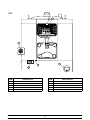
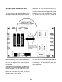
Measure between the GND terminal and the pin
of T2 nearest U2 (see drawing). The resistance
should be from 110 to 160 ohms. If not, replace
the board. If so, go to Section C.
If you have gotten this far, the Power Board is not
defective. Re--install it into the freezer and replace the
Logic Board Assembly. The Logic Board Assembly
consists of a metal panel with a printed circuit board,
the red status LEDs and the operator buttons. The self
test that can be performed on the Generation II Logic
Board.
If the machine continues to fail, re--install the original
Logic Board Assembly and continue to troubleshoot
the freezer. Pay special attention to loose or defective
connectors.
If you have reached this step, the Power Board is
probably defective. If one of the DC voltage checks
brought you here, the Logic Panel could be loading
down the Power Board. To find out:
Note: Indicate any discrepancies of the part on the
part return tag. Example: “No 24 volt,” etc.
Turn the power off and unplug the J1 cable
connector from the Power Board.
Models C706 & C707
Apply power and repeat steps 3 and 4 in the
previous section. If the voltage measurements
are acceptable, reconnect the connector and go
to Section C. Otherwise, go to the next step.
C. Check Logic Board
B. Check Power Board Immediately After
Removal
1.
2.
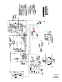
See the Power Board Troubleshooting Flowchart on
the next page.
25
Controls