1
OPERATING/SERVICE INSTRUCTIONS
IM). Connect the hose /tube assembly to the pump and
tube puller assembly. Hydraulic connections push together
until they snap. Control tube connections should be properly keyed and threaded securely.
When the pump motor is started, the ram will (if not fully
forward) move to the full reset position, build enough pressure to trip an internal unloader, and then idle.
FULL SYSTEM PRESSURIZING OF THE RETURN HOSE
AT THE RESET POSITION INDICATES A MALFUNCTION
OF THE PUMP - immediately stop the motor by pushing
the red button on the pump and/turning of the air shut-off
valve and clear the malfunction before proceeding. Cycle
the puller assembly several times to warm the system before setting the gripper.
GRIPPER ADJUSTMENT
Pull the trigger until the gripper starts to move (the draw
rod moves about 3/8" first) to put the puller in the grippersetting position. Turn the motor off (by pushing the red
MOTOR STOP button on the pump) and measure the diameter of the back tooth. If it is not at least .020" larger
than the ID of the tube to be pulled, adjust the expansion
nut in until it is. Make sure that the correct gripper size is
being used since over-expansion of an undersized gripper
will decrease gripper life.
NOTE: Very hard tubes cannot be pulled in a conventional
manner with this tool since the gripper teeth will slide instead of gripping into the surface of the tube. Tighten the
lock nut against the expansion nut and confirm that the
draw rod is tight. Install the nose bushing and lock it in
place with one of the set screws.
SERVICE INSTRUCTIONS
Most hydraulic cylinders give relatively long life and good
dependability when they are used within their design parameters. The use of approved clean hydraulic fluid is essential if good seal life is to be expected (see pump manual
#90120-IM). It is also essential that care be taken when
coupling the hoses to the cylinder and pump to avoid getting dirt or other contamination into the system where it
could abrade the seals and cause them to leak.
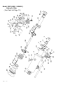
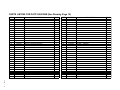
DISASSEMBLY (Refer to the exploded view drawing on
the following page for the item numbers referenced.) Note:
All threaded components have right-hand threads.
HANDLE/ LIMIT SWITCH REMOVAL
1. Clamp the puller upside down in a soft jaw vise so that
the puller is securely held with the hydraulic connections pointed up.
2. Remove switch cover screws (6) and cover (8).
3. Remove the limit valve mounting screws (10 ).
-continued-
4. Remove the handle mounting screw (41). Loosen the
handle mounting set screws (38), and remove the handle
assembly, tubing conduit (14) and limit valve (11) assembly, taking care not to damage the tubes when
pulling them through the slot in the switch box.
5. Inspect the valve roller and arm for free operation and
clean if necessary, or replace if damaged.
6. Carefully inspect the handle tubing for deterioration,
damage or loose connections and replace if required.
CYLINDER DISASSEMBLY
It is strongly recommended that PATP cylinders be returned
to Airetool for repairs involving removal of the cylinder plug.
The following instructions are provided for use only by knowledgeable service personnel using appropriate facilities and
equipment.
1. Remove the gripper retainer (1), gripper, draw rod, nose
bushing, and gripper adapter (2).
2. Unscrew the nose bushing adapter (3).
3. Thoroughly clean all exposed surfaces of the puller with
a suitable solvent and blow dry.
NOTE:
All further operations must be performed in a
thoroughly clean environment to avoid premature failure of
the puller or pumping unit due to contamination.
4. Remove the hydraulic couplings (12 and 13) and drain
out as much of the hydraulic fluid as possible.
5. Securely attach a heavy steel bar to the ¼-20 threaded
holes in the cylinder plug with three grade 8 cap screws
and loosen the plug. The cylinder must be held securely toward the nose end of the cylinder and with the
torque reacted against the suspension eye boss and
not the hose connections.
6. Remove the cylinder plug and any hydraulic fluid remaining in the cylinder. Inspect the O-ring (33) and replace if cut or worn.
7. Using a suitable drift to avoid damaging the rod threads,
carefully press the piston assembly out of the case.
Take care to catch the oil remaining below the piston
assembly.
8. Pull the piston (29) assembly out of the outside piston
(20) assembly.
9. Inspect the rod seal (25) and piston seals (24) for cuts
or wear, but do not attempt to remove them unless replacement is intended. To remove a rod or piston seal,
pull the seal away from the piston (or rod) and very carefully cut through the seal with a very sharp, thin blade,
taking care to avoid scratching the piston or rod.
10. The valve plunger (30) and spring (31) can be removed
from the piston (29) after unscrewing the set screw (32).
11. The valve seat (23) can be unscrewed from the outside
piston (20) to remove the ball (22) and spring (21). The
spring should be approximately 1 1/8” long. If it has
Page - 7