1
04 - 12
Ed. 004
Painting
OPERATING AND
MAINTENANCE INSTRUCTIONS
II 2 G c IIB T4
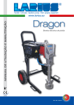
PA I N T S P R AY I N G E Q U I P M E N T
ENGLISH
LARIUS 2 - painting
O AIR CONTROL GROUP WITH
INTRODUCTION.................................................p.1
A
B
C
D
E
F
G
H
WORKING PRINCIPLE.......................................p.2
TROLLEY............................................................p.20
TECHNICAL DATA...............................................p.2
P AIR CONT. GROUP WITHOUT TROLLEY Inox. ..........p.21
DESCRIPTION OF THE EQUIPMENT................p.3
Aluminium version....................................... p.22
TRANSPORT AND UNPACKING........................p.5
Q
O FILTER WITH CIRCULATION Stainless steel model...........p.23
SAFETY RULES..................................................p.5
Aluminium version...............................................p.24
SETTING-UP.......................................................p.6
R SUCTION LINE FILTER .....................................p.25
OPERATION........................................................p.8
S
T
U
V
O
W
X
CLEANING AFTER THE SPRAY PAINTING OR IN
CASE OF PRODUCT CHANGE..........................p.9
I ROUTINE MAINTENANCE.................................p.10
J TROUBLESHHOTING.........................................p.11
K L2 PUMP Stainless steel version............................p.12
SUCTION TANK MODEL.....................................p.26
WALL-MOUNTED MODEL..................................p.27
DESCRIPTION....................................................p.28
TECHNICAL FEATURES....................................p.28
MARKING............................................................p.28
SAFETY INSTRUCTIONS FOR INSTALLATION
Aluminium version...............................................p.14
Y IN HAZARDOUS AREAS....................................p.29
L TANK...................................................................p.16
M BASKET FULL.....................................................p.17
N FLOW CONTROLLER.........................................p.18
EXAMPLE OF INSTALLATION............................p.29
Read this operator’s manual
carefully before using the
equipment. An improper use
of this machine can cause
injuries to people or things.
It indicates an
accident risk or
serious damage
to equipment if
this warning is not
followed.
Z DECLARATION OF CONFORMITY....................p.34
It indicates a fire
or explosion risk if
this warning is not
followed.
It is obligatory to wear suitable clothing as gloves,
goggles and face shield.
WE ADVISE THE USE OF THIS EQUIPMENT ONLY BY PROFESSIONAL OPERATORS.
ONLY USE THIS MACHINE FOR USAGE SPECIFICALLY MENTIONED IN THIS MANUAL.
Thank you for choosing a LARIUS S.R.L. product. As well as the product purchased,
you will receive a range of support services enabling you to achieve the results desired,
quickly and professionally.
1
It indicates important
recommendations
about disposal
andrecycling
process of products
in accordance with
the environmental
regulations.
English
PNEUMATIC DOUBLE DIAPHRAGM PUMP
LARIUS 2 - painting
The LARIUS 2 can also be used as a transfer pump.
The LARIUS 2 unit is defined as being a “diaphragm pump” that
is used for low pressure painting. This type of equipment can be
used to paint using a number of spray guns.
The feed passes through a low pressure flow regulator, fitted with
a pressure gauge.
B TECHNICAL DATA
RATIO 1:1
LARIUS 2
MAX WORKING PRESSURE (product)
7 bar
MAX (air) SUPPLY PRESSURE
7 bar
AIR INLET PRESSURE
7 bar
PUMP AIR CONSUMPTION
120 L/min
WEIGHT
22 Kg
LEVEL OF THE SOUND PRESSURE
≤ 70dB(A)
LENGTH
WIDTH
(A) 500 mm
(B) 600 mm
HEIGHT
(C) 1060 mm
C
English
A WORKING PRINCIPLE
A
B
2
LARIUS 2 - painting
C DESCRIPTION OF THE EQUIPMENT
English
4
2
3
1
9
4
10
5
8
6
7
POS.
POS.
Description
Description
1
Trolley
6
Product outlet
2
Tank cover
7
Product recycling tap
3
Gravity feed tank with 6 liters capacity
8
Product recycling hose
4
Product filter
9
Pump feeding air inlet
5
Flow regulator
10
Pump feeding air outlet
3
English
LARIUS 2 - painting
19
11
14
16
13
12
17
15
18
POS.
POS.
Description
Description
11
Air distribution tap
16
Product pressure setting knob
12
Atomising air outlet
17
Air pressure gauge for pump supply
13
Atomizing air pressure manometer
18
Pilot valve
14
Atomizing air pressure setting knob
19
Spray gun
15
Product inlet
4
LARIUS 2 - painting
D TRANSPORT AND
UNPACKING
•
Before installing the equipment, ensure that the area to
be used is large enough for such purposes, is properly
lit and has a clean, smooth floor surface.
The behaviour of the employees shall strictly
comply with the Accident prevention AND
ALSO ENVIRONMENTAL regulations in force in
the country where the plant is installed and
used.
Read carefully and entirely the following
instructions before using the product. Please
save these instructions in a safe place.
• The user is responsible for the operations of unloading
and handling and should use the maximum care so as
not to damage the individual parts or injure anyone.
To perform the unloading operation, use only qualified
and trained personnel (truck and crane operators, etc.)
and also suitable hoisting equipment for the weight of the
installation or its parts.
Follow carefully all the safety rules.
The personnel must be equipped with the necessary
safety clothing.
The unauthorised tampering/replacement of
one or more parts composing the machine,
the use of accessories, tools, expendable
materials other than those recommended by
the Manufacturer can be a danger of accident.
The Manufacturer will be relieved from tort and criminal
liability.
•
KEEP YOUR WORK PLACE CLEAN AND TIDY. DISORDER
WHERE YOU ARE WORKING CREATES A POTENTIAL
RISK OF ACCIDENTS.
•
ALWAYS KEEP PROPER BALANCE AVOIDING UNUSUAL
STANCE.
• Check the packing is undamaged on receipt of the equipment. Unpack the machine and verify if there has been
any damage due to transportation.
In case of damage, call immediately LARIUS and the
Shipping Agent. All the notices about possible damage or
anomalies must arrive timely within 8 days at least from
the date of receipt of the plant through Registered Letter
to the Shipping Agent and to LARIUS.
•
BEFORE USING THE TOOL, ENSURE THERE ARE NOT
DAMAGED PARTS AND THE MACHINE CAN WORK PROPERLY.
•
ALWAYS FOLLOW THE INSTRUCTIONS ABOUT SAFETY
AND THE REGULATIONS IN FORCE.
•
Keep those who are not responsible for the
equipment out of the work area.
• The disposal of packaging materials is a customer’s
competence and must be performed in accordance with
the regulations in force in the country where the plant is
installed and used.It is nevertheless sound practice to
recycle packaging materials in an environment-friendly
manner as much as possible.
•
NEVER exceed the maximum working pressure
indicated.
•
NEVER point the spray gun at yourselves or at
other people.THE CONTACT WITH THE CASTING CAN
CAUSE SERIOUS INJURIES.
•
In case of injuries caused by the gun casting,
seek immediate medical advice specifying the
type of the product injected. Never undervalue a wound caused by the injection of a
fluid.
•
Always DISCONNECT THE SUPPLY AND release the
pressure in the circuit before performing any
check or part replacement of the equipment.
•
NEVER MODIFY ANY PART IN THE EQUIPMENT. CHECK
REGULARLY THE COMPONENTS OF THE SYSTEM.
REPLACE THE PARTS DAMAGED OR WORN.
•
Tighten and check all the fittings for
• The manufacturer will not be responsible for the unloading
operations and transport to the workplace of the machine.
E SAFETY RULES
•
The employer shall train its employees
about all those risks stemming from accidents, about the use of safety devices for
their own safety and about the general
rules for accident prevention in compliance with international regulations and with
the laws of the country where the plant
is used.
5
English
• The packed parts should be handled as indicated in the
symbols and markings on the outside of the packing.
LARIUS 2 - painting
connection between pump, flexible hose and
spray gun before using the equipment.
•
Always use the flexible hose supplied with
standard kit. THE USE OF ANY ACCESSORIES OR
TOOLING OTHER THAN THOSE RECOMMENDED IN
THIS MANUAL, MAY CAUSE DAMAGE OR INJURE THE
OPERATOR.
English
•
Electrical safety precautions
The fluid contained in the flexible hose can
be very dangerous. Handle the flexible hose
carefully. Do not pull the flexible hose to
move the equipment. Never use a damaged or
a repaired flexible HOSE.
•
Check the "ON/OFF" switch is on the "OFF" position before
connecting the cable to the mains.
•
Never carry a plugged-in equipment.
•
Disconnect the equipment before storing it and before
performing any maintenance operation or replacing of accessories.
Do not carry the equipment neither unplug it by pulling the
electric cable.
Protect the cable from heat, oil and sharp edges.
•
The high speed of travel of the product in the hose can
create static electricity through discharges
and sparks. It is suggested to earth the
equipment.
The pump is earthed through the earth cable
of the supply.
The gun is earthed through the high pressure flexible hose.
All the conductors near the work area must be earthed.
•
•
•
When the tool is used outdoors, use only an extension cable
suited for outdoor use and so marked.
Never attempt to tamper with the calibre of
instruments.
NEVER SPRAY OVER FLAMMABLE PRODUCTS OR
SOLVENTS IN CLOSED PLACES.
NEVER USE THE TOOLING IN PRESENCE OF POTENTIALLY EXPLOSIVE GAS.
•
Take care when the pumping rod is moving.
Stop the machine whenever someone is within its vicinity.
•
Repairs of the electrical equipment should only be carried
out by skilled personnel, otherwise considerabledanger to
the user may result.
F SETTING-UP
Always check the product is compatible with the materials
composing the equipment (pump, spray gun,
flexible hose and accessories) with which it
can come into contact. Never use paints or
solvents containing Halogen Hydrocarbons
(as the Methylene Chloride).
If these products come into contact with aluminium parts can
provoke dangerous chemical reactions with risk of corrosion
and explosion.
CONNECTION OF THE FLEXIBLE HOSE TO THE GUN
• Connect the dual hose to the pump and the spray gun, making
sure that the connections are properly tight (it is best to use
two spanners).
Never use sealants on fittings’ threads.
• It is recommended to use the hose provided with the standard
kit (rif. 8151).
NEVER use a damaged or a repaired flexible hose.
condiTIONS OF GUARANTEE
The conditions of guarantee do not apply in the
following situations:
- improper washing and cleaning of components
causing malfunction, wear or damage to the
equipment or any of its parts;
- improper use of the equipment;
- use that does not conform with applicable national
legislation;
- incorrect or faulty installation;
- modifications, interventions and maintenance that
have not been authorised by the manufacturer;
- use of non-original spare parts or parts that do
not correspond to the specific model;
- total or partial non-compliance with the instructions provided.
IF THE PRODUCT TO BE USED IS TOXIC, AVOID INHALATION
AND CONTACT BY USING PROTECTION GLOVES, GOGGLES
AND PROPER FACE SHIELDS.
TAKE PROPER SAFETY MEASURES FOR THE PROTECTION
OF HEARING IN CASE OF WORK NEAR THE PLANT.
6
LARIUS 2 - painting
WASHING OF THE NEW EQUIPMENT
•
•
Clean hoses (F1) and (F2) by blowing compressed air before
connecting them.
Point the gun at the solvent tank and press the trigger so as
to recover the residual solvent.
• Close the pressure setting knob (F3).
Do not set the pump to work without product,
because this could spoil its gaskets.
F1
Absolutely avoid to spray solvents indoors. In
addition, it is recommended to keep away from
the pump in order to avoid the contact with the
solvent fumes.
F2
•
•
Now the machine is ready. Should you use water paints,
besides the solvent wash, a wash with soapy and then clean
water is suggested.
Make sure that the atomising air supply is shut off.
PREPARATION OF THE PAINT
• Make sure the product is suitable to be used with a spray
gun.
• Mix and filter the product before using it.
•
Rotate the pressure setting knob (F3) slightly clockwise so
that the machine operates at minimum power.
Make sure the product to be used is compatible
with the materials employed for manufacturing
the equipment (stainless steel, aluminium and
carbon steel). Because of that, please contact
the supplier of the product.
F3
Never use products containing halogen hydrocarbons (as
methylene chloride). If these products come into contact with
aluminium parts of the equipment, can provoke dangerous
chemical reactions with risk of explosion.
7
English
•
• Point the gun at a container keeping the trigger pressed (so
as to drain the oil inside) till a clean solvent comes out. Now,
release the trigger.
The equipment has already been adjusted at our factory with
light mineral oil left inside the pumping group as protection. As
soon as the connections have been carried out, before putting
the product in the tank, it is necessary to rinse the pump by
means of the circulation of solvent (thinner for paints).
LARIUS 2 - painting
G OPERATION
English
G1
G3
G5
G4
G2
G2
G7
G10
G9
G6
G8
START OF THE PAINTING OPERATIONS
(G7); the pressure must be of roughly 6 bar, max. 7,5 bar.
• Use the tooling after performing all the SETTING UP operations
above described.
•
Open the recycling tap (G8).
•
Start pump by means of the knob (G9); the pump will be set
to work. Let the product recycle for a short period (2 minutes)
and then close the recycling tap (G8).
• Fill tank (G1) with pure and perfectly filtered product.
•
Connect up the product hose (G2) from the spray gun (G3)
to the flow regulator (G4).
•
Set the atomizing air pressure by means of the knob
(G10).
•
Connect up the air hose (G5) from the spray gun (G3) to the
coupling (G6).
•
Make a spraying test.
•
Connect the compressed air plant to the quick connection
•
The pump is now ready to work.
8
LARIUS 2 - painting
SPRAY ADJUSTMENT
•
•
•
Always paint with regular parallel bands coats.
•
Keep a safety and constant distance between the gun and the
support to be painted and also keep yourselves perpendicular
to it.
An irregular and marked spray on the sides indicates a low
working pressure. On the contrary, a too high pressure causes
a high fog (“overspray”) and waste of product.
Never point the spray gun at yourselves or at
other people. The contact with the casting can
use serious injuries. In case of injuries caused by
the gun casting, seek immediate medical advice
specifying the type of the product injected.
In order to avoid overthickness of paint, let the gun advance
sideways (right-left) when spraying.
H CLEANING AFTER THE
SPRAY PAINTING OR IN
CASE OF PRODUCT CHANGE
• Reduce product pressure to the minimum (0,5-1 bar) by
means of knob (H1).
•
Put back the recycling hose (H4) into the tank (H3).
•
Use knob (H2) to set the air atomisation knob to zero.
•
Pour some solvent in the tank (H3).
•
Disconnect the return hose (H4) from tank (H3) and introduce
it into an empty can for recuperating the product.
•
Open the recycling tap (H5), set the product pressure at the
minimum value by means of the knob (H1).
•
Open the recycling tap (H5) and let the pump work until the
tank and the pump itself have been emptied.
•
The pump will be set to work. Let the solvent recycle for a
short time and then close the recycling tap (H5).
•
Close the recycling tap (H5).
•
Unscrew the atomizing head (H6) and rinse it with the solvent,
put it back and by means of the spray gun discharge in a tank
the product left until the solvent comes out.
H1
H3
H6
H2
H5
H4
9
English
•
Slowly turn the knob on the flow regulator clockwise, until
a pressure is obtained that guarantees good atomisation of
the product.
English
LARIUS 2 - painting
•
With the spray gun over the thinner tank, press the trigger
in order to let the thinner circulate during at least five minutes.
•
If necessary change the thinner and repeat this operation
more times until all the residues of the product will have been
eliminated.
•
Clean the product hose (H7) by means of a rag and wash
the filters (H8), (H9) and (H10) with the solvent.
•
After the use of products with a base of polyvinyl alcohol or
of water soluble products, first clean the pump with water
and then let some alcohol circulate through the plant.
If it is foreseen a long period of standstill for
the pump, after the cleaninng let some light
mineral oil circulate in order to protect it against
corrosion.
H8
H9
H7
H10
I ROUTINE MAINTENANCE
•
Check that all the hose connections are tight.
•
Clean and, if necessary, replace the worn seals.
•
Check filters (I1), (I2) and (I3) and replace them when necessary.
•
Check the nozzle on the spray gun and clean it.
I1
I3
I2
10
LARIUS 2 - painting
J TROUBLESHOOTING
•
The equipment does not suck the
Solution
Cause
•
Suction filter clogged;
•
Clean or replace it;
•
Suction filter too fine;
•
Replace it with a larger-mesh filter
product
(with very dense products, remove
the filter);
•
The equipment suck but does not
•
The equipment sucks air;
•
Check the suction pipe;
•
Lack of product;
•
Add the product;
•
The equipment sucks air;
•
Check the suction pipe;
•
The circulation tap is open;
•
Close the circulation tap;
•
Nozzle too big or worn;
•
Replace it with a smaller one;
•
The product is too dense;
•
Dilute the product, if possible;
•
The nozzle is partially clogged;
•
Clean or replace it;
•
There is no atomising air;
•
Check the flow regulator for the
reach the pressure desired
•
When pressing the trigger, the
pressure lowers considerably
•
The pressure is normal but the
product is not atomized.
atomising air;
•
Leakage from the seal-tightening
•
The product is too dense;
•
Dilute the product, if possible;
•
Gasket worn or needs adjustment;
•
Replace or adjust the gasket;
•
The nozzle is worn;
•
Replace it;
screw
•
The atomization is imperfect
11
English
Problem
LARIUS 2 - painting
English
K STAINLESS STEEL L2 PUMP
12
LARIUS 2 - painting
Code
N°
Pos.
Code
N°
1
8134
2
Flange
27
8005
2
O ring
2
8039
4
O ring
28
8004
2
Seal ring seat
3
91641
2
Lower ball Ø3/4"
29
8006
2
Seal ring
4
8016
2
Lower ball seat
30
8021
2
Pilot pad
5
8017
2
Upper ball Ø9/16"
31
8009
2
Elstic ring
6
8015
2
Upper ball seat
32
8010
1
Elastic pin
7
8148
1
Lower manifold
33
8043
2
O ring
8
8147
8
Support
34
8008
1
Rod
9
8158
2
Selflocking nut
35
8001
1
Pump body
10
8138
2
Membrane pressing
38
8047
12
Screw
11
301013
4
O ring
39
8054
2
Silencer
12
8056
1
Fitting
40
8026
2
Grub screw
16
8136
1
Upper manifold
41
4006
1
Fitting
20
8027
1
Pilot valve
53
35005/1
1
Filter bell
21
8012
2
Membrane pressing
54
35006
1
Fine filter
22
8084
2
Screw
55
35007
1
Coarse filter
23
8013
2
PTFE membrane
56
35008
1
Elastic ring
24
8014
2
Rubber membrane
57
35004
25
8011
2
Washer
58
8117
26
8007
2
Elastic ring
Description
13
Description
Complete filter
1
Rigide tube
English
Pos.
17
8
14
9
8
13
12
1
6
2
4
2
14
12
5
10
3
10
20
18
11
19
16
7
10
15
21
22
23
20
19
25
24
27
26
28
32
31
30
29
36
31
33
28
46
42
35
43
44
45
27
25
48
47
26
23
37
39
24
20
41
19
38
40
22
21
18
20
19
5
3
6
2
4
2
1
34
English
LARIUS 2 - painting
ALUMINIUM L2 PUMP
LARIUS 2 - painting
Codice
N°
Pos.
Codice
N°
1
8002
2
Flange
25
8005
2
O ring
2
8039
4
O ring
26
8004
2
Seal ring seat
3
91641
2
Lower ball Ø3/4"
27
8006
2
Seal ring
4
8016
2
Lower ball seat
28
8021
2
Pilot pad
5
8017
2
Upper ball Ø9/16"
29
8009
2
Elastic ring
6
8015
2
Upper ball seat
30
8010
1
Elastic pin
7
8040
1
Lower manifold
31
8043
2
O ring
8
33010
4
Washer
32
8008
1
Rod
9
32108
2
Plug 3/8" GAS
33
8001
1
Pump body
10
8071
3
Washer
34
8047
12
Screw
11
8108
1
Plug 1/2" GAS
35
8054
2
Silencer
12
8058
2
Fitting 1/2" GAS
36
8026
2
Grub screw
13
8022
2
Bracket
37
8055
1
Fitting
14
7043
4
Screw
38
3344
1
Pressure regulator
15
8003
1
Upper manifold
39
8032
1
"I" fitting
16
8037
4
Screw
40
3338
1
Bayonet fitting
17
8020
2
Plug
41
8031
1
Fitting ¼”-Ø4
18
8158
2
Nut
42
8044/1
1
Hose
19
8012
4
Membrane pressing
43
3343
1
Fitting
20
301013
4
O ring
44
3341
1
Union elbow
21
8013
2
PTFE membrane
45
8167
1
Manometer
22
8014
2
Rubber membrane
46
8056
1
Fitting
23
8011
2
Washer
47
8027
1
Pilot valve
24
8007
2
Elastic ring
48
8084
4
Screw
Descrizione
15
Descrizione
English
Pos.
LARIUS 2 - painting
English
L TANK
Pos.
Code
Pos.
Code
1
55000
Cover
8
4122
Bracket
2
35008
Elastic ring
9
22097
Fitting Ø12
3
35006
Fine filter
10
96217
Hose Ø12
4
35007
Coarse filter
11
54004
Screw
5
8085
Rigid tube
12
91026
Nut
6
18170
Hose Ø10
13
55001
Hopper
7
4123
Fitting
Description
16
Description
LARIUS 2 - painting
M COMPLETE TROLLEY
English
2
1
3
4
4
3
4
4
5
5
Pos.
Code
N°
96320/1
Pos.
Code
N°
Complete trolley
3
91023
2
Wheels
Description
Description
1
21653
1
Trolley frame L1-L2
4
95159
4
Wheel washer
2
91047
1
Plug Ø 30
5
8018
2
Feet Ø 20
17
LARIUS 2 - painting
English
N FLOW REGULATOR
18
LARIUS 2 - painting
Pos.
Code
Description
Pos.
Code
7185
Alluminium fluid regulator with
14
7223
Retainer
15
7222
Valve rod
1
7234
Key
16
7510
Alluminium body
2
7211
Cap of regulator
17
7225
Seat valve
3
7212
Screw
18
7220
Ball
4
7240
Screw
19
7226
Nut
5
7213
Nut
20
7235
Swivel joint (3/8" GAS)
6
7214
Nut
21
7237
Screw
7
7217
Screw
22
33011
Carbon steel fitting (GAS)
8
7215
Gasket
23
5255
Union elbow
9
7522
Gasket
24
8064
Connector
10
7521
Washer
25
11623
Washer
11
7520
Diaphragm (nylon)
26
8168
Fluid pressure gauge
12
7518
Gasket
27
7218
Standard spring (0-4 bar)
13
7519
Diaphragm (teflon)
27
7209
Special spring (0-7 bar)
Pos.
Code
Description
Pos.
Code
Description
7201
Stainless steel fluid regulator with
14
7223
Retainer
15
7222
Valve rod
manometer
1
7234
Key
16
7510
Stainless steel body
2
7211
Cap of regulator
17
7225
Seat valve
3
7212
Screw
18
7220
Ball
4
7240
Screw
19
7226
Nut
5
7213
Nut
20
7235/1
6
7214
Nut
21
7237
Screw
7
7217
Screw
22
6147
Stainless steel fitting (GAS)
8
7215
Gasket
23
5255
Union elbow
9
7522
Gasket
24
8064
Connector
10
7521
Washer
25
11623
Washer
11
7520
Diaphragm (nylon)
26
8168
Fluid pressure gauge
12
7518
Gasket
27
7218
Standard spring (0-4 bar)
13
7519
Diaphragm (teflon)
27
7209
Special spring (0-7 bar)
19
Swivel joint (3/8" GAS)
English
manometer
Description
LARIUS 2 - painting
English
O air control group on trolley
12
11
10
4
9
12
11
8
1
6
4
9
3
5
2
5
2
3
7
13
Pos.
Code
N°
96322
Pos.
Code
N°
Complete group
8
4004
1
Ball valve 1/4"
Description
Description
1
4006
1
Quick coupling 1/4" tube Ø 8
9
5255
2
Elbow 1/4"
2
8167
2
Manometer
10
3338
1
Bayonet fitting
3
3344
2
Regulator
11
91026
2
Nut M6
4
510510
2
Regulators bracket
12
54004
2
Screw UNI 5931 TCE M6x16
5
3354
2
Adapter 1/4"
13
96208
1
Nipple 1/4"
6
8072
1
Fitting 1/4"
7
8031
1
Quick connection 1/4" tube Ø 4
20
LARIUS 2 - painting
P air control group WITHOUT trolley
INOX VERSION
English
11
10
3
12
13
14
8
5
4
9
7
2
1
8
6
15
Pos.
Codice
N°
Pos.
Codice
N°
1
8170
1
Adjustable brackets
9
96208
1
Junction 1/4"
2
54004
8
Screw
10
8073
1
Block air
3
8167
2
Manometer
11
3354
2
Junction
4
22027
1
Junction
12
8083
1
Stopper 1/4"
5
3344
2
Reg pressure
13
8063
1
Swivel Elbow
6
4004
1
Ball valve
14
8084
2
Screw
7
3338
1
Bayonet
15
11209
2
Nut
8
5255
1
Fitting elbow
Descrizione
21
Descrizione
LARIUS 2 - painting
English
ALUMINIUM VERSION
8
8
10
12
6
11
6
9
1
13
1
7
5
3
2
Pos.
Codice
N°
1
3344
2
2
8060
3
4
Pos.
Codice
N°
Reg pressure
8
8167
2
Manometer
1
Adjustable brackets
9
96208
1
Junction 1/4"
3338
1
Bayonet
10
8083
1
Stopper 1/4"
4
8031
1
Junction 1/4" - Ø4
11
8073
1
Block air
5
32004
2
Vite
12
8063
1
Swivel Elbow
6
3354
2
Junction
13
4004
1
Ball valve
7
5255
1
Fitting elbow
Descrizione
22
Descrizione
LARIUS 2 - painting
Q FILTER WITH CIRCULATION
Pos.
Code
1
8096
2
98384
3
N°
English
STAINLESS STEEL MODEL
Pos.
Code
N°
Complete filter
10
8123
1
Elbow
1
Filter tank
11
8156
1
Revolving fitting
96202
1
Elastic ring
12
98385
1
Plug 3/8"
4
95220
1
Filter sieve 100 M
13
98386
1
Plug 1/4" GAS
5
96207
1
Filter sieve support
14
33010
1
Washer
6
96203
1
O ring
15
8074
1
Elbow
7
98380
1
Filter base
16
6149
1
Fitting
8
22027
1
Fitting
17
8057
1
Filter fitting
9
4004
1
Ball valve
Description
23
Description
LARIUS 2 - painting
English
ALUMINIUM MODEL
Pos.
Code
1
8049
2
96201
3
N°
Pos.
Code
N°
Complete filter
10
8123
1
Elbow
1
Filter tank
11
8069
1
Revolving fitting
96202
1
Elastic ring
12
95214
1
Plug 3/8"
4
95220
1
Filter sieve 100 M
13
96205
1
Plug 1/4" GAS
5
96207
1
Filter sieve support
14
33010
1
Washer
6
96203
1
O ring
15
8087
1
Elbow
7
96204
1
Filter base
16
3561
1
Fitting
8
22027
1
Fitting
17
8057
1
Filter fitting
9
4004
1
Ball valve
Description
24
Description
LARIUS 2 - painting
R SUCTION LINE FILTER
English
COMPLETE SUCTION FILTER
Pos.
Code
1
8107
2
8052
3
N°
COMPLETE DROP FILTER
Pos.
Code
Complete filter
1
8113
1
Filter tank
2
8052
1
Filter tank
16205
1
Filter sieve 60 M
3
16205
1
Filter sieve 60 M
4
96203
1
O ring
4
96203
1
O ring
5
96204
1
Filter base
5
96204
1
Filter base
6
96205
1
Plug 1/4" GAS
6
96205
1
Plug 1/4" GAS
7
8069
1
Revolving fitting
7
8069
1
Revolving fitting
8
16202
1
Filter sieve support
8
16202
1
Filter sieve support
9
22027
1
Fitting
9
22027
1
Fitting
10
4004
1
Ball valve
10
4004
1
Ball valve
11
8123
1
Elbow
11
5314
1
Elbow
12
8057
1
Filter fitting
12
8057/1
1
Filter fitting
13
33010
1
Washer
13
33010
1
Washer
14
8087
1
Elbow
14
8087
1
Elbow
15
3561
1
Fitting
15
3561
1
Fitting
Description
25
N°
Description
Complete filter
LARIUS 2 - painting
English
S SUCTION TANK MODEL
Pos.
Code
N°
1
4109
1
Complete cover
2
4064
1
30 Liters tank
4
8046
1
Product hose
5
35005/1
1
Filter bell
6
35006
1
Fine filter
7
35007
1
Coarse filter
8
35008
1
Elastic ring
9
8041
1
Complete suction pipe with
Description
filter
26
LARIUS 2 - painting
T WALL-MOUNTED MODEL
English
Pos.
Codice
N°
1
4202
1
Wall bracket
2
8036
1
1/2" elbow
3
8131
1
Suction hose
4
35005
1
Bell
5
35006
1
Fine sieve filter
6
35007
1
Coarse sieve filter
7
35008
1
Elastic ring
8
35004
1
Complete filter bell
Description
27
LARIUS 2 - painting
These safety instructions are related to installation, use and service
for use of transfer low pressure double diaphragm pumps – series
2 and 4 – in potentially explosion Hazardous environments due
to presence of gas or vapour.
The double diaphragm pumps series 2 and
4 are group II equipment, suitable to use in
areas classified with iresence of gas and
vapour (Category 3G, group IIB). The pumps
are designed and manufactured to suit the
rules ATEX 94/9/CE and the European Rules:
EN 1127-1, EN 13463-1ed EN 13463-5.
These instructions must be followed as
further precautions to those already listed
within the use and service instruction
manual.
V TECHNICAL FEATURES
Low pressure transfer double diaphragm pumps series 2 and 4.
Environment temperature: -10°C÷+50°C
Max. fluid temperature [°C]: 60°C
Max. air temperature [°C]: 30°C
LOW PRESSURE TRANSFER DOUBLE
DIAPHRAGM PUMPS
SERIE 2 LARIUS
SERIE 4 LARIUS
PRESSURE RATIO
1:1
1:1
PUMP FEEDING AIR PRESSURE
[bar]
1÷7
2÷8
1/4" GAS
1/4" GAS
MAX. FLUID DELIVERY [l/min.]
21
40
MAX. AIR CONSUMPTION [l/min.]
120
190
PUMP FEEDING AIR INLET
W MARKING
Low pressure double diaphragm transfer pumps series 2 and 4.
3
English
U DESCRIPTION
X
II 2 G c IIB T4
Tamb: -10°C ÷ + 50°C
Tmax. fluido: 60°C
Tech. File: LARIUS 2-4/ATEX/05
II =
Group II ( surface)
2=
Category 2 (zone 1)
G=
Explosion hazardous environment with presence of gas, fog and vapour
c=
Manufacturing safety "c"
T4 =
Class of temperature T5
- 10°C ÷ + 50°C
Environment temperature
60°C
xxxxx/AA
Maximum fluid temperature
Serial number xxxxx = PROGRESSIVE/ year = AA
28
LARIUS 2 - painting
Relation between hazardous areas, products and categories
CATEGORIES AS PER RULES
94/9/CE
Gas, vapour or fog
Zone 0
1G
Gas, vapour or fog
Zone 1
2G or 1G
Gas, vapour or fog
Zone 2
3G, 2G or 1G
X SAFETY INSTRUCTIOINS
FOR ONSTALLATIONS IN HAZARDOUS AREAS
Before proceeding with the installation
carefully read the use and service manual.
All the service operations must be carried
out as stated in the manual.
The low pressure double diaphragm
transfer pumps series 2 and 4 must not
work empty of material.
All the operations, installation and service,
must be carried out by qualified operators.
•
The low pressure double diaphragm transfer pumps series
2 and 4 must be connected to the ground with a suitable
connector anti-release and anti-rotation.
• Gas and vapour of flammable liquids must belong to the
group IIB and compatible with class temperature T4.
Y EXAMPLE OF INSTALLATION
• According with the nature of the operations and products, the
operator must regularly check the presence of deposit, the
cleaning, the wearing and the correct pump’s functioning.
• It is advisable that a filter will be placed at the suction of the
material to prevent solid parts entering the pump.
• The pipes used to connect suction and delivery must be
metallic, or plastic with metallic braid or plastic with fabric
braid with suitable earthing cable.
•
According to duties it is recommended the control of diaphragms and replacement.
•
The air feeling the pump needs to be filtered and originated
by a safe area.
29
The picture shows a typical example of installation of a Larius
double diaphragm pump.
English
DANGEROUS AREA
LARIUS 2 - painting
We
Larius S.r.l.
Via Stoppani, 21
24032 Calolziocorte (LC)
The conformity are under observance of the following standards or standards documents:
declare under our sole responsibility that the product
- EN 1127-1
- EN 13463-1
Marking
Low pressure transfer double diaphragm pumps - series 2 and 4.
- Directive 94/9/EC
EN 13463-5
II 2 G c IIB T4 Tamb.: - 10°C ÷ 50°C Tmax. fluido: 60°C
Tech. File: LARIUS 2-4/ATEX /05
X file c/o: INERIS (0080)
Technical
to which this declaration relates complies with the
following Directives:
-
3
English
DECLARATION OF CONFORMITY
(ATEX)
Calolziocorte- LC
30
Signature
A
C
C
E
S
S
O
R
I
E
S
Code 14090: SPRAY GUN V71P
Code 14132: NOZZLE 0,8 mm
Code 14092: NOZZLE 1,0 mm
Code 14090: NOZZLE 1,3 mm
Code 14096: NOZZLE 1,5 mm
Code 14134: NOZZLE 1,8 mm
Code 7208: STAINLESS STEEL 0-14 BAR
RETURN REGULATOR
Code 8131: SUCTION RETURN SYSTEM
Code 8144: SUCTION RETURN SYSTEM (stainless steel)
Code 7185: FLOW REGULATOR
Code 16205: FILTER SIEVE 60 MESH
Code 16204: FILTER SIEVE 100 MESH
Code 16203: FILTER SIEVE 200 MESH
Code 16205/10: FILTER SIEVE 60 MESH 10 pcs
Code 16204/10: FILTER SIEVE 100 MESH 10 pcs
Code 16203/10: FILTER SIEVE 200 MESH 10 pcs
SUCTION BELL KIT
Code 35004: FILTER BELL - Code 35006: FILTER 100 MESH
Code 35007: FILTER 50 MESH - Code 35007/1: FILTER 30 MESH
Code 55007:
6LT DROP TANK
Code 8107: SUCTION LINE FILTER
Code 8113: DROP LINE FILTER
LINEA DIRETTA
SERVIZIO TECNICO CLIENTI
Tel. (39) 0341.621256 - Fax (39) 0341.621234
COSTRUTTORE:
PA I N T
S P R AY I N G
EQUIPMENT
23801 CALOLZIOCORTE - LECCO - ITALY - Via Antonio Stoppani, 21
Tel. (39) 0341/62.11.52 - Fax (39) 0341/62.12.43
E-mail: [email protected] - Internet http://www.larius.com
LARIUS 2 - painting
English
33
English
LARIUS 2 - painting
Due to a constant product improvement programme, the factory reserves the right to modify
technical details mentioned in this manual without prior notice.
34
PNEUMATIC PUMPS
NOVA Ref. 95040
OMEGA Ref. 7300
GHIBLI Ref. 96000
VEGA Ref. 91500
OMEGA ZINC Ref. 7430
GHIBLI ZINC Ref. 96900
MANUFACTURER:
23801 CALOLZIOCORTE - LECCO - ITALY - Via Stoppani, 21
Tel. (39) 0341/62.11.52 - Fax (39) 0341/62.12.43
E-mail: [email protected] - Internet http://www.larius.com
DIRECT LINE
CUSTOMERS TECHNICAL SERVICE
Tel. (39) 0341/621256
Fax (39) 0341/621234