1
L
A
U
T
N
S
I
A
L
M
&S
E
T
C
R
I
A
V
P
R
E
S
Company Name:
N
O
I
T
A
R
E
G
I
R
F
E
R
T
S
E
R
E
V
E
m
o
6 c
8 .
5 n
6 o
- i
3 t
2 a
. 3 r
4
E
e
)2
g
V60
i
A415r
7
37f
L0(
-e
L9
I 53r
2
T
HA83
S
DC2)
E
N,60
R
AN-1E
43
SO4
S
(V
.R
4 E
:
E
X.
)A
W
7A0
6C0
FW
9 8
W
(
:
: E
E
T
N I
O S
H B
P E
W
ERSD06-01
EPRL06-01
(Feb. 2007)
Version:
S
E
C
I
T
O
N
Y
T
E
F
A
S
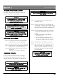
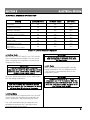
As you work on the reach-in, be sure to pay close
attention to the safety notices in this manual.
Disregarding the notices may lead to serious personal
injury and/or damage to the reach-ins.
The following types of safety notices will be seen
throughout the manual.
WARNING
Text in a "WARNING"box alerts you to a potential
personal injury situation. Be sure to read the
warning statement before proceeding,
and work carefully.
CAUTION
Text in a "CAUTION" box alerts to a potential
situation in which damage to the reach-in
may occur. Be sure to read the caution
statement before proceeding, and work carefully.
S
E
C
I
T
O
N
L
A
R
U
D
E
C
O
R
P
When working on the reach-in, be sure to read
the procedural notices in the manual. These
notices supply helpful information which may
assist in the work.
You will see the following types of procedural
notices, throughout the manual.
IMPORTANT
Text in an "IMPORTANT" box will provide
information that may helpful to perform a
procedure more efficiently. Disregarding
this information will not cause damage or
injury, but it may slow you down.
TABLE OF CONTENTS
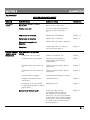
SECTION 1 - GENERAL INFORMATION
Page
ABOUT MODELS, SERIAL NUMBERS AND BARCODES……………………………………1
Location of Label……………………………………………………………………… 1
About Model Numbers…………………………………………………………………1
About Serial Numbers………………………………………………………………… 1
About Barcodes…………………………………………………………………………1
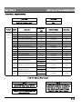
MODELS INCLUDED IN THIS SERVICE MANUAL……………………………………………1
SECTION 2 - WARRANTY
WARRANTY COVERAGE…………………………………………………………………………2-1
Warranty Claims…………………………………………………………………………2-1
One (1) Year Parts & Labor……………………………………………………………2-1
Five (5) Year Compressors……………………………………………………………2-1
Instant Six Months Ext. Warranty…………………………………………………… 2-1
Additional Warranty…………………………………………………………………… 2-1
WARRANTY EXCLUSIONS……………………………………………………………………… 2-1
WARRANTY SERVICE LABOR ALLOWANCE………………………………………………… 2-2
MATERIAL COST ALLOWANCE…………………………………………………………………2-3
VERIFICATION OF WARRANTY…………………………………………………………………2-3
WHEN SUBMITTING WARRANTY BILL TO MANUFACTURER………………………………2-3
SECTION 3 - INSTALLATION
WHERE TO INSTALL………………………………………………………………………………3-1
ELECTRICAL REQUIREMENTS………………………………………………………………… 3-2
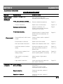
SECTION 4 - MAINTENANCE
INTERIOR AND EXTERIOR CLEANING…………………………………………………………4
LIGHT BULB REPLACEMENT……………………………………………………………………4
CONDENSER CLEANING…………………………………………………………………………4
SECTION 5 - CONTROL SYSTEM
ABOUT CONTROL BOX………………………………………………………………………… 5-1
HOW TO SET DESIRED TEMPERATURE ………………………………………………………
5-1
Single Temperature Units………………………………………………………………5-1
Dual Temperature Units ……………………………………………………………… 5-1
FACTORY PRESET…………………………………………………………………………………
5-1
Temperature Preset…………………………………………………………………… 5-1
Defrost Cycle Preset……………………………………………………………………5-1
ABOUT PCB CONTROL MODES (NEW Control System)……………………………………5-2
For SINGLE temperature units
ABOUT PCB CONTROL MODES (NEW Control System)……………………………………5-2-1
For DUAL temperature units
MODE CHANGES FOR SINGLE TEMP UNITS (NEW Control System) ……………………
5-3, 5-4
MODE CHANGES FOR DUAL TEMP UNITS (NEW Control System) ………………………
5-4
CONTROL CIRCUIT BOARD WIRING DIAGRAN (NEW: AS-50 TYPE)……………………5-6 ~ 5-8
ABOUT PCB CONTROL MODES (OLD Control System)……………………………………5-9
MODE CHANGES FOR SINGLE TEMP UNITS (OLD Control System)……………………5-10
CONTROL ERROR (NEW System)………………………………………………………………5-11
SECTION 6 - ELECTRICAL SYSTEM
ELECTRICAL SEQUENCE OF OPERATION……………………………………………………6
Cooling Cycle……………………………………………………………………………6
Defrost Cycle ……………………………………………………………………………6
TABLE OF CONTENTS
OFF Cycle ……………………………………………………………………………… 6
SECTION 7 - REFRIGERATION SYSTEM
SCHEMATIC OF CONDENSING UNIT OF UPRIGHT REACH-INS………………….
COMPRESSOR INFORMATION………………………………………………………
7-1
7-2
SECTION 8 - COMPONENT REPLACEMENT
B
L
U
B
T
H
G
I
L
T
E
K
C
O
S
B
L
U
B
T
H
G
I
L
R
E
T
A
E
H
N
A
P
E
T
A
S
N
E
D
N
O
C
C
I
R
T
C
E
L
E
001
9111
---8888
H
C
T
I
W
S
T
H
G
I
L
EVAPORATOR DRAIN COVER……………………………………………………………………
8-1
EVAPORATOR MOTOR & FAN BLADES………………………………………………………8-2
DEFROST HEATER……………………………………………………………………………… 8-3
CABINET TEMPERTURE SENSING BULD…………………………………………………… 8-4
OVERHEAT PROTECTOR SENSING BULB……………………………………………………8-4
CONDENSER FAN MOTOR AND BLADES…………………………………………………… 8-5
DOOR GASKET……………………………………………………………………………………8-6
DOOR……………………………………………………………………………………………… 8-7
DOOR TENSION ADJUSTMENT…………………………………………………………………8-8
DOOR HANDLE……………………………………………………………………………………8-9
Y
L
B
M
E
S
S
A
X
O
B
L
O
R
T
N
O
C
2
1
8
)
S
(
D
R
A
O
B
T
I
U
C
R
I
C
2
1
8
SECTION 9 - DIAGNOSTICS
Reach-In does not run ………………………………………………………………………… 9-1
Main power button on control box is OFF …………………………………………9-1
Voltage is too low ………………………………………………………………………9-1
Control box is defective ………………………………………………………………9-1
Compressor is defective ………………………………………………………………9-1
Relay / capacitor is defective ……………………………………………………… 9-1
Delay time ……………………………………………………………………………… 9-1
Cabinet does not maintain proper temperature …………………………………………… 9-1
High pressure in refrigeration system ………………………………………………9-1
System is in "Defrost Cycle" …………………………………………………………9-1
Refrigerant charge is low because of gas leak ……………………………………9-2
Temperature control problem …………………………………………………………
9-2
Condenser coil is too dirty ……………………………………………………………9-2
Frozen evaporator coil …………………………………………………………………9-2
Compressor does not operate …………………………………………………………………9-2
Wiring problem …………………………………………………………………………9-2
Relay is defective ………………………………………………………………………9-2
Capacitor is defective …………………………………………………………………9-2
Compressor is defective ………………………………………………………………9-2
Door(s) is difficult to open ………………………………………………………………………
9-2
Pressure relief control is not functioning ………………………………………… 9-2
Wrong installation ………………………………………………………………………9-2
Water is leaking ………………………………………………………………………………… 9-3
In the cabinet ……………………………………………………………………………9-3
Out of the cabinet ………………………………………………………………………9-3
Noise ……………………………………………………………………………………………… 9-3
In the cabinet ……………………………………………………………………………9-3
Out of the cabinet …………………………………………………………… 9-3
FLOW CHART - POSSIBLE CAUSES………………………………………………………… 9-4
SUMMARY OF DIAGNOSTIC TIPS………………………………………………………………9-5
N
O
I
T
A
M
R
O
F
N
I
L
A
R
E
N
E
G
1
N
O
I
T
C
E
S
S
R
E
B
M
U
N
L
A
I
R
E
S
D
N
A
S
L
E
D
O
M
B
1
C
2
D
3
E
4
F
5
G
6
H
7
I
8
J
9
K
0
[Table 1-1: Alphabet Conversion Table]
L
A
U
N
A
M
E
C
I
V
R
E
S
S
I
H
T
N
I
D
E
D
U
L
C
N
I
S
L
E
D
O
M
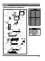
When a service is required, a service technician will
need to provide the model and serial number of the
defect unit. Without the serial number, the manufacturer
cannot supply right parts and support the service
technician with right technical information.
l
e
b
a
L
f
o
n
o
i
t
a
c
o
L
.
a
The model and serial number are located on
the inside left wall of the reach-in, see Figure
1-1.
b. About Model Numbers
<Example>
ESR1 - "E" stands for "Everest"
- "S" stands for "Solid Door"
- "R" stands for "Refrigerator"
- "1" means number of doors
ESRF2 -
"E" stands for "Everest"
"S" stands for "Solid Door"
"RF" stands for "Ref & Fzr"
"2" means number of doors
c. About Serial Numbers
<Example>
BSR1-0106-0001
- "B" stands for "Busung", factory name
- "S" stands for "Solid Door"
- "R" stands for "Refrigerator"
- "1" means number of doors
- "0106" means year (2001) and month (June)
- "0001" means 1st unit made in June 2001
MODEL
ESR1
ESRH2
ESR2
ESWR2
ESR3
1
2
2
2
3
ESGR1
ESGR2
ESWGR2
1 Glass Door Upright Refrigerator
2 Glass Door Upright Refrigerator
2 Glass Wide Door Upright Refrigerato
ESF1
ESFH2
ESF2
ESWF2
ESF3
1
2
2
2
3
Door Upright Freezer
Half Door Upright Freezer
Door Upright Freezer
Wide Door Upright Freezer
Door Upright Freezer
ESRF2
ESWQ3
ESWRF2
ESRF3
2
1
2
3
Door Uprigt Dual Temps
Full & 2 Half Wide Door Dual Temps
Wide Door Uprigt Dual Temps
Door Upright Dual Temps
DESCRIPTION
Door Upright Refrigerator
Half Door Upright Refrigerator
Door Upright Refrigerator
Wide Door Upright Refrigerator
Door Upright Refrigerator
d. About Barcodes
Barcodes have been printed on the label from
March 2003 to present.
<Example>
BKDKE0001A
Alphabet stands for number, see Table 1-1.
-
"B" stands for "Busung", factory name
"KD" means Year; "03", 2003
"KE" means Month; "04", April
"0001" means 1st unit made in April 2003
"A" means export product
LABEL
[Figure 1-1: Location of Label]
1
E
G
A
R
E
V
O
C
Y
T
N
A
R
R
A
W
e. Additional Warranty
An extended parts and labor warranty is
available for purchase which covers a
second year.
S
N
O
I
S
U
L
C
X
E
Y
T
N
A
R
R
A
W
CAUTION
No warranty coverage applies when
refrigeration system or reach-in cabinet is
used in conjunction with other products.
Y
T
N
A
R
R
A
W
2
N
O
I
T
C
E
S
Everest warrants only the original purchaser of the
Everest unit(s) and all parts to be free from defects
in material or workmanship under normal and proper
use, and maintenance.
from Jan. 2004)
The following items are not included in the warranty
coverage.
a. Nomal maintenance, adjustments, and cleaning.
a. Warranty Claims
All claims for labor and parts must be made
directly through Everest and assigned Everest
dealers or distributors. All claims should
include model and serial number of the unit,
proof of purchase, date of installation and
all pertinent information supporting the
existence of the alleged defect.
b. One (1) Year for Parts & Labor
Parts and labor warranty is limited to a period
of one (1) year from the date of installation or
fifteen (15) months after shipment from
Everest's warehouse if the warranty registration
card(s) is not returned.
c. Five (5) Year for Compressors
Everest warrants five (5) years on the
hermetically sealed compressor itself, not to
exceed sixty (60) months from the date of
shipment from Everest's warehouse.
This compressor warranty does not apply to
parts such as electrical components,
accumulator, condensing & evaporator coil,
wiring harness etc. These items are covered
by the one (1) year standard warranty.
b. Interior cabinet light bulb.
c. Repairs due to unauthorized modifications to all
Everest products or the use of non-standard parts
without prior written approval from the
manufacturer.
d. Improper electrical connections resulting from
electrical power failures, the use of extension
cords, and low voltage or voltage drops to the unit.
e. Damage caused by improper installation, electrical
supply, water supply or drainage; floods, storms,
and/or other acts of God.
f. Parts or assemblies subjected to misuse, abuse,
neglect, and/or accidents.
g. Damage to the interior of the cabinet or
refrigeration system as a result of storing open
acidic food containers.
h. Claims for special, indirect or consequential
damages including, without limitation, food
spoilage or product loss.
i. Outside of the United States.
d. Instant Six Months Ext. Warranty
EVEREST offers an instant additional six (6)
months parts & labor warranty to only
purchaser who returns the warranty card to
EVEREST headquarter office within a month
from the date of installation, which is
enclosed in the user’s manual. If not, the
purchasers will have the standard one (1)
year parts & labor warranty only.
(This special offer has been provide to all
customers who purchased Everest product
j. Warranty is limited to only the original purchaser.
It is not transferable.
k. Premium labor rates due to holidays, overtime,
etc.; travel time; flat rate service call charges;
mileage and miscellaneous tools and material
charges not listed on the payment schedule.
Additional labor charges resulting from the
inaccessibility of the refrigeration system/reach-in
cabinet are also excluded.
2-1
Y
T
N
A
R
R
A
W
2
N
O
I
T
C
E
S
E
C
N
A
W
O
L
L
A
R
O
B
A
L
E
C
I
V
R
E
S
Y
T
N
A
R
R
A
W
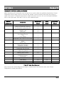
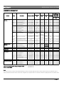
When submitting a bill for warranty work, the labor hours must be within the guidelines listed below. Everest
Refrigeration has the right to pay no more than the average commercial hourly rates within the territory or
region of the repair. To diagnose and repair or replace more than one item, use up to the highest allowable
time for the single repair, then add1/2 hour for each additional repair.
Name of
Components
All Freon Leak
Compressor
Coil
Door
Drainage
Electrical Wire
Fan Motor
Heater
Lighting
Sensor
Control System
Vacuum Control
Valve
Defrost
Others
Description
At any joint in the system
Compressor
Relay/Overload/Start Capacitor
Self Contained Condensing Unit
Evaporator/Condenser
Capillary Tube
Filter Drier
Door Hinge
Door Spring Tension
Door
Door Gasket
U-Trap (or P-Trap)
Evaporator Drain Cover w/ Pan Heater
Harness
Wiring
Power Cord
Condenser/Evaporator Fan Blades
Evaporator Fan Motor
Condenser Fan Motor
Defrost Heater
Condensate Pan & Heater
Light Bulb Socket
Light (Door) Switch
Overheat Protect (Evap) Sensor
Cabinet (Room) Sensor
PCB Board
PCB Mode Changes
Transformer
Pressure(Vacuum) Relief Control
Soleniod Valve
Other Valves
Evaporator Coil
All Other Parts' Replacements
Replacement
Repair
Adjustment
(Hour)
(Hour)
2-3
(Hour)
2-3
1
2
2-3
1-2
1-2
1
1
1
1
1
1
1
1
1
1
1
1
1
1
1
1
1
1-2
1-2
1-2
1
1
1
2-3
2-3
1
1
2-3
2-3
1
[Table 2-1: Labor Hour Allowance]
Above hourly rate includes diagnosis and repair or replacement of the defective parts under Everest
Refrigeration's warranty procedures.
2-2
Y
T
N
A
R
R
A
W
2
N
O
I
T
C
E
S
Maximum Pay
Access valve
$5.00
Nitrogen
$5.00
R134A refrigerant per system $15.00
R404A refrigerant per system $20.00
Refrigerant recovery
$20.00
Vacuum
$0.00
Welding Material
$20.00
Material
O
T
L
L
I
B
Y
T
N
A
R
R
A
W
G
N
IR
TE
TR
IU
MT
BC
UA
SF
NU
EN
HA
WM
E
C
N
A
W
O
L
L
A
T
S
O
C
L
A
I
R
E
T
A
M
The table shows the maxium that the manufacturer will
pay for the listed materials on a warranty claim.
1. Service company should supply below information.
a. Model & Serial number
b. Installation Date
c. Correct customer's Information
2. The service bill should be summited within a
month from the date of service.
Y
T
N
A
R
R
A
W
F
O
N
O
I
T
A
C
I
F
I
R
E
V
The manufacturer will refuse to pay for the warranty
claim to the service company if anything of above
information was not provided.
1. Service company must verify warranty status of
product through below methods before a
warranty work begins if the waranty work was
not directly ordered by the manufacturer.
Failure to do so, the manufacturer has a right to
refuse to pay the warranty labor claim.
a. By the receipt of product from the customer or
dealer/distriburor where the product purchased
from
b. Contact the manufacturer (1-800-444-6285)
to verify the status
Note:
The product information will not be found in
the system if the customer did not return the
warranty card to the manufacturer.
Please read the "SECTION 2" about the warranty
coverage.
2-3
S
E
C
N
E
R
E
F
E
R
N
O
I
T
A
L
L
A
T
S
N
I
3
N
O
I
T
C
E
S
L
L
A
T
S
N
I
O
T
E
R
E
H
W
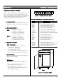
CEILING
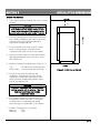
1. The product shoul be instaledl the unit on a level
surface.
CAUTION
20"
Drain & temperature problems will be occurred
if the product tilts even slightly froward or back.
Please adjust the height of the caster(s) for the
product to be leveled by using washer if required.
2. The unit is designed for indoor and commercial
use. Outdoor installation will cause a decrease
in performance and significant damage if
exposed to sunlight and rain.
W
A
L
L
3. Do not install the unit under a shelf or place
where a foreign object could fall into the
condensing unit area; on top of the cabinet.
6"
4. Select a location away from heat and moisture
generating equipment such as a stove, oven,
dish washer, etc.
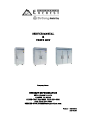
5. Minimum Clearance Requirements [Figure 3-1]
FLOOR
Top
: 20" above the condensing unit
Back & Side : 6" at the back and each side
[Figure 3-1: Side View of Cabinet]
6. Do not tilt the unit during delivery and
installation. Compressor oil might run into
condensing coil through high pessure pipe,
which causes a tempressure problem due to
clog in the capillary tube.
CAUTION
If minimun clearances are not maintained,
cooling capacity will be reduced. This may
lead to product loss or premature
component failure.
6. Four casters supplied by manufacturer must
be installed. Failure to do that, it will cause
a malfunction of condensate pan heater
which was built-in underneath of the cabinet.
7. Ambient Temperaure for Condenser
Minimum
: 50F
Maximum
: 100F
3-1
S
E
C
N
E
R
E
F
E
R
N
O
I
T
A
L
L
A
T
S
N
I
3
N
O
I
T
C
E
S
S
T
N
E
M
E
R
I
U
Q
E
R
L
A
C
I
R
T
C
E
L
E
CAUTION
All wiring must conform to local,
state and national codes.
Product
Model
Description
CAUTION
Never use an extention
cord.
Compressor
Volt/Cycle/Phase
Total Amps
1/3
115V/60/1
3.38
1/3
115V/60/1
3.38
1/3
115V/60/1
4.5
(HP)
Upright
Reach
-Ins
ESR1
1 DR Upright Refrigerator
ESRH2 2 Half Door Upright Refrigerator
ESR2
2 DR Upright Refrigerator
ESWR2 2 DR Wider Upright Refrigerator
1/3
115V/60/1
4.5
1/3 X 2
115V/60/1
9.49
ESGR1 1 Glass Door Refrigerator
1/3
115V/60/1
4.5
ESGR2 2 Glass Door Refrigerator
1/2
115V/60/1
4.5
1/2
115V/60/1
8.12
1/2
115V/60/1
8.12
1/2
115V/60/1
8.12
ESR3
3 DR Upright Refrigerator
ESWGR2 2 Wide Glass Door Refrigerator
ESF1
1 DR Upright Freezer
ESFH2 2 Half Door Upright Freezer
ESF2
2 DR Upright Freezer
ESWF2 2 DR Wider Upright Freezer
ESF3
3 DR Upright Freezer
ESRF2 2 DR Uprigt Dual Temp
1/2 X 2
115V/60/1
15.89
1/2 X 2
115V/60/1
15.89
1/2 X 3
208-230V/60/1
12.36
115V/60/1
12.08
115V/60/1
12.08
115V/60/1
12.08
115V/60/1
12.62
1/3 (Ref)
1/2 (Fzr)
ESWRF2 2 DR Wider Uprigt Dual Temp
1/3 (Ref)
1/2 (Fzr)
ESWQ3
2 Section 3/4 Refrigerator & 1/4
Freezer Dual Temp
ESRF3 3 DR Upright Dual Temp
1/3 (Ref)
1/2 (Fzr)
1/3 (Ref)
1/2 (Fzr)
[Table 3-1: Electrical Requirements]
NOTE
It will take about one (1) minute to
operate the system after plug-in.
NOTE
Plug for ESF3 is not provided from
the manufacturer.
NOTE
There is a 5 second time delay on
compressor operations for reach-ins
that have two or three condensing
units. (Model ESF2, ESWF2, ESRF2,
ESWRF2, ESR3, ESF3, ESRF3)
3-2
E
C
N
A
N
E
T
N
I
A
M
4
N
O
I
T
C
E
S
G
N
I
N
A
E
L
C
R
O
I
R
E
T
X
E
D
N
A
R
O
I
R
E
T
N
I
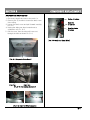
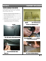
Use ONLY stainless steel cleaner to clean the
interior and exterior of the cabinet.
IMPORTANT
Use this procedure to clean the condenser
once a month
WARNING
Exterior stainless steel is made of 430
series material which might be rusted
if it is cleaned by a cleaner other than
general stainless steel ones.
Step 1 Unscrew and remove the gray plastic
condenser cover.
CAUTION
Never use steel wool; strong acids, or
abrasive cleaners to clean any interior or
exterior of the cabinet.
Step 2 Clean the outside of the condenser with
a soft brush or vacuum with a brush. Clean
from the top to the bottom, not side to side.
Be careful not to bend the condenser fins.
CAUTION
Acidic products or products containing
vinegar must be stored in sealed containers
to prevent acid damage to the interior of the
cabinet and evaporator coil.
T
N
E
M
E
C
A
L
P
E
R
B
L
U
B
T
H
G
I
L
Step 1 Unscrew and remove the white plastic
protective cover over the light bulb.
Step 2 Unscrew and remove the used light bulb.
Step 3 Install a new 25 watt appliance light bulb.
(Be sure it is screwed in securely)
Step 4 Reinstall the protective cover over the
light bulb.
(Be sure it is screwed in securely)
G
N
I
N
A
E
L
C
R
E
S
N
E
D
N
O
C
A dirty condenser restricts airflow, resulting in
excessively high operating temperatures. This
reduces efficiency and shortens component life.
Step 3 Shine a flashlight through the condenser
to check for dirt between the fins. If dirt
remains:
a. Blow compressed air through the
condenser coil.
b. Use a commercial condenser coil
cleaner. Follow the directions and any
precautions supplied with the cleaner.
Step 4 Repeat Step 3 until all dirt is removed.
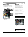
Step 5 Carefully wipe off the fan blade and motor
with a soft cloth. Do not bend the fan
blades. If the fan blades are excessively
dirty, wash with warm, soapy water and
rinse thoroughly.
CAUTION
If you are cleaning the condenser
fan blades, cover the fan motor
to prevent water damage.
WARNING
Disconnect the electric power to the unit
before cleaning the condenser.
WARNING
The condenser fan blade is sharp. Be
careful when cleaning.
4
M
E
T
S
Y
S
L
O
R
T
N
O
C
5
N
O
I
T
C
E
S
X
O
B
L
O
R
T
N
O
C
T
U
O
B
A
2. Dual Temperature Units
1. General
All electrical operations for Everest products are
governed by a microchip installed control box,
including the compressor, door heater, condensate
pan heater, defrost heater, condensing &
evaporator fan motor, lighting, temperature,
setting, changing control modes; see page 5-2.
2. Circuit Boards
The control system is composed of two curcuit
boards.
a.
Main(LED) Circuit Board
- contains microchip, LED & buttons
b.
Power Circuit Borad
- contains relays & wire pins
E
R
U
T
A
R
E
P
M
E
T
D
E
R
I
S
E
D
T
E
S
O
T
W
O
H
Please make sure that the main power is connected
to 115V/60Hz power supply. And the power button is
"ON".
Step 1 Push the "TEMP. SET" button. Refrigerator
side light will blink.
Step 2 While the light is blinking, set your desired
temperature by pushing the "HIGH" or
"LOW" button.
Step 3 The LED read-out will display the actual
temperature of the cabinet a few seconds
later if the above procedures are
successfully completed.
Step 4 Push the "TEMP SET" button twice.
Freezer side light will blink.
Step 5
Repeat Step 2 for setting the freezer side
temperature.
Step 6 Push the "TEMP. SET" button to check for
your new desired temperature; pushing once
for refrigerator and twice for freezer.
1. Single Temperature Units
Step 1 Push the"TEMP. SET" button. The red
light will blink.
Step 2 While the light is blinking, set your
desired temperature by pushing the "HIGH"
or "LOW" button.
`
Step 3 The LED read-out will display the actual
temperature of the cabinet a few seconds
later if the above procedures are
successfully completed.
Step 4 Push the "TEMP. SET" button to check
for your new desired temperature.
[Pic. 5-2: Dual Temperature Unit Control Box]
Location of Display Windows for Dual Temps
: Left (REF) Right (FZR)
Upright Duals
Undercounter Duals : Left (FZR) Right (REF)
S
T
E
S
E
R
P
Y
R
O
T
C
A
F
1. Temperature Preset
- Refrigerator : 35F
- Freezer
: -4F
[Pic. 5-1: Single Temperature Unit Control Box]
2. Defrost Cycle Preset
- Four (4) times a day for both refrigerator and
freezer.
5-1
M
E
T
S
Y
S
L
O
R
T
N
O
C
5
N
O
I
T
C
E
S
)
m
e
t
s
y
S
l
o
r
t
n
o
C
D
L
O
(
S
E
D
O
M
L
O
R
T
N
O
C
B
C
P
T
U
O
B
A
l
a
i
r
e
s
e
l
b
a
c
i
l
p
p
a
e
h
T
.
2
5
e
l
b
a
T
n
i
w
o
l
e
b
n
w
o
h
s
s
a
s
e
d
o
m
e
e
r
h
t
e
v
a
h
s
e
x
o
b
l
o
r
t
n
o
c
d
l
o
e
h
T
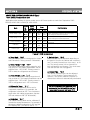
numbers are on all Everest reach-ins made from April 2001 to August 2002; from BXXX(X)0104-0001 to BXXX(X)-0208-XXXX.
Mode
Symbol on
LED
Ref
Fzr
Temp. Range - High
R3
F1
Temp. Range - Low
R4
F2
Defrost Cycle
R5
F5
Factory
Preset
Ref Fzr
Range
Brief Description
Ref
Fzr
-22F to -22F to Highest temperature range the unit can go up to
54F 54F
86F
86F
when setting desired temperature.
-22F to -22F to Lowest temperature range the unit can go down
33F -15F
86F
86F
to when setting desired temperature.
Interval time (hour) of defrost operation
06
06 01 to 24 01 to 24
[Table 5-2: Control Modes]
a.Temperature Range - High "R3" or "F1"
The highest temperature setting range the unit
can go up to. The highest temperature can be
adjusted from -22F to 86F. Factory preset is
54F for both refrigerators and freezers.
c. Temperature Range - Low "R4" or "F2"
The lowest temperature setting range the unit
can go down to. The lowest temperature can
be adjusted from -22F to 86F. Factory preset is
33F for refrigerators and -15F freezers.
f. Defrost Cycle "R5" or "F5"
Defrost cycles can be adjusted depending on
the type of food in the cabinet and customer's
use. It is set by interval time; from every 1 to 24
hrs. The factory preset is 6 hrs intervals for both
refrigerators and freezers. The clock starts from
the time the unit is plugged in.
5-2-1
M
E
T
S
Y
S
L
O
R
T
N
O
C
5
N
O
I
T
C
E
S
S
T
I
N
U
P
M
E
T)
m
Ee
Lt
Gs
Ny
IS
S
l
o
Rt
r
On
Fo
SC
Ee
Gp
Ny
AT
HR
CS
EB
DD
L
OO
M(
IMPORTANT
Please read and completely understand
page 5-2-1 before adjusting any modes.
Open the top grill to reach the control box, and make
sure the power is "ON".
a. Tmpeerature Range - High
c. Defrost Cycle
Step 1 Press and hold the "TEMP SET" button
for a few seconds until "R3" for Ref.
(or "F1" for fzr.) is displayed on the LED
read-out. Now you are in theTemperature
Range - High Mode. You can check the
factory preset for this mode by pushing
the "HIGH" or "LOW" button once.
Step 1 Press and hold the "TEMP SET" button
for a few seconds until "R3" for Ref.
(or "F1" for fzr.) is displayed on the LED
read-out. Now you are in theTemperature
Range - High Mode. You can check the
factory preset for this mode by pushing
the "HIGH" or "LOW" button once.
Step 2 Reset the new highest temperature in the
range by pushing the "HIGH" or "LOW"
button. The LED will display the cabinet
temperature after a few seconds. This
means that the reset has been successfully
completed.
Step 2 Push the "TEMP SET" button twice. You
will see "R4" for ref. (or fzr for "F-5") on
the LED. You can check the factory preset
for this mode by pushing the "HIGH" or
"LOW" button once.
Step 3 Reset the new number of hour intervas for
the defrost cycle by pushing the "HIGH"
or "LOW" button. The LED will display
cabinet temperature a few seconds later.
This means that the reset has been
successfully completed.
b. Temperature Range - Low
Step 1 Press and hold the "TEMP SET" button
for a few seconds until "R3" for Ref.
(or "F1" for fzr.) is displayed on the LED
read-out. Now you are in theTemperature
Range - High Mode. You can check the
factory preset for this mode by pushing
the "HIGH" or "LOW" button once.
Step 2 Push the "TEMP SET" button one more
time. You will see "R4" for ref. (or "F-2"
for fzr.)on the LED. You can check the
factory preset for this mode by pushing
the "HIGH" or "LOW" button once.
Step 3 Reset the new lowest temperature in the
range by pushing the "HIGH" or "LOW"
button. The LED will display the cabinet
temperature after a few seconds. This
means that the reset has been successfully
completed.
5-2-2
M
E
T
S
Y
S
L
O
R
T
N
O
C
5
N
O
I
T
C
E
S
)
e
p
y
T
0
5
S
A
s
(t
i
Sn
Eu
De
Or
u
Mt
a
Lr
Oe
Rp
Tm
Ne
Ot
CE
L
BG
CN
PI
TS
Ur
Oo
BF
A-
;
2
0
0
2
r
e
b
m
e
t
p
e
S
m
o
r
f
e
d
a
m
s
t
c
u
d
o
r
p
t
s
e
r
e
v
E
l
l
a
n
o
e
r
a
s
e
d
o
m
e
s
e
h
t
r
o
f
s
r
e
b
m
u
n
l
a
i
r
e
s
e
l
b
a
c
i
l
p
p
A
BXXX(X)-0209-0001 to BXXX(X)-0506-XXXX.
Mode
Symbol
on
LED
Factory
Preset
Ref
Fzr
Temp. Mark
C-F
F
F
Temp. Range - High
H-1
54F
54F
Temp. Range - Low
L-1
33F
-15F
Temp. Differential
F-1
03F
02F
Calibration
S-1
00
00
Defrost Cycle
S-3
06
06
Defrost Time
S-4
Range
Brief Description
Ref
Fzr
N/A
-22F to
86F
-22F to
86F
N/A
-22F to
86F
-22F to
86F
Celsius or Fahrenheit
Highest temperature range the unit can go up to
when setting the desired temperature.
Lowest temperature range the unit can go down
to when setting the desired temperature.
Differential temperature when compressor stops
2 to 6
2 to 6
and restarts.
-20F to -20F to Calibration of temperature sensing bulb.
20F
20F
Interval time(hour) of defrost operation.
01 to 24 01 to 24
20 Min 20 Min 01 to 60 01 to 60 Operation time(minute) of defrost.
[Table 5-1: PCB Control Modes]
a. Temp Mark "C-F"
The PCB control system is designed for Celsius
and Fahrenheit. Factory preset is "Fahrenheit".
b. Temp. Range - High "H-1"
The highest temperature setting range the unit
can go up to. The highest temperature can be
adjusted from -22F to 86F. Factory preset is
54F for both the refrigerators and freezers.
c. Temp. Range - Low "L-1"
The lowest temperature setting range the unit
can go down to. The lowest temperature can be
adjusted from -22F to 86F. Factory preset is
33F for refrigerators and -15F for freezers.
f. Defrost Cycle "S-3"
Defrost cycles can be adjusted depending on
the types of food in the cabinet and customer's
use. It is set by interval time; from every 1 to 24
hrs. The factory preset is 6 hrs intervals for
both refrigerators and freezers. The clock starts
from the time the unit is plugged in.
g. Defrost Time "S-4"
The defrost operation time can be adjusted
from 1 to 20 minutes. Factory preset is 20
minutes. If the sensor reads 61F winthin 20
minutes then defrost is automatically terminated.
IMPORTANT
d. Differential Temp. "F-1"
A differential temperautre can be set for
compressor operations. For example, the
refrigerator is preset at 35F. The compressor
stops when the cabinet temperature reaches
32F and restarts at 38F (3F differential).
The defrost operation is terminated by both
requirements; time (within 20 minutes) and
temperature (evaporator coil temp: 61F).
e. Calibration "S-1"
The cabinet sensing bulb can be calibrated if
it reads the wrong temperature. For example, if
the actual cabinet temperature is 30F, but the
LED displays 35F, you have to set at "-5".
5-3-1
M
E
T
S
Y
S
L
O
R
T
N
O
C
5
N
O
I
T
C
E
S
)
e
p
y
T
0
5
S
A
(
Ss
t
Ei
Dn
Ou
e
Mr
u
Lt
Or
a
Re
Tp
Nm
Oe
Ct
BL
CA
PU
TD
Ur
Oo
BF
A-
;
2
0
0
2
r
e
b
m
e
t
p
e
S
m
o
r
f
e
d
a
m
s
t
c
u
d
o
r
p
t
s
e
r
e
v
E
l
l
a
n
o
e
r
a
s
e
d
o
m
e
s
e
h
t
r
o
f
s
r
e
b
m
u
n
l
a
i
r
e
s
e
l
b
a
c
i
l
p
p
A
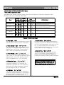
BXXX(X)-0209-0001 to BXXX(X)-0506-XXXX.
Mode
Symbol
on LED
Ref
Fzr
Factory
Preset
Ref
Fzr
Temp. Mark
C-F
C-F
F
F
Temp. Range - High
H-1
H-2
54F
54F
Temp. Range - Low
L-1
L-2
33F
-15F
Temp. Differential
F-1
F-2
03F
02F
Calibration
S-1
S-2
00
00
Defrost Cycle
S-3
S-5
06
06
Defrost Time
S-4
S-6
Range
Brief Description
Ref
Fzr
N/A
-22F to
86F
-22F to
86F
N/A
-22F to
86F
-22F to
86F
Celsius or Fahrenheit
Highest temperature range the unit can go up to
when setting the desired temperature.
Lowest temperature range the unit can go down
to when setting the desired temperature.
Differential temperature when compressor stops
2 to 6
2 to 6
and restarts.
-20F to -20F to Calibration of temperature sensing bulb.
20F
20F
Interval time(hour) of defrost operation.
01 to 24 01 to 24
20 Min 20 Min 01 to 60 01 to 60 Operation time(minute) of defrost.
[Table 5-1: PCB Control Modes]
a. Temp Mark "C-F"
The PCB control system is designed for Celsius
and Fahrenheit. Factory preset is "Fahrenheit".
b. Temp. Range - High "H-1" or "H-2"
The highest temperature setting range the unit
can go up to. The highest temperature can be
adjusted from -22F to 86F. Factory preset is
54F for both the refrigerators and freezers.
c. Temp. Range - Low "L-1" or "L-2"
The lowest temperature setting range the unit
can go down to. The lowest temperature can be
adjusted from -22F to 86F. Factory preset is
33F for refrigerators and -15F for freezers.
f. Defrost Cycle "S-3" or "S-5"
Defrost cycles can be adjusted depending on
the types of food in the cabinet and customer's
use. It is set by interval time; from every 1 to 24
hrs. The factory preset is 6 hrs intervals for
both refrigerators and freezers. The clock starts
from the time the unit is plugged in.
g. Defrost Time "S-4" or "S-6"
The defrost operation time can be adjusted
from 1 to 20 minutes. Factory preset is 20
minutes. If the sensor reads 61F winthin 20
minutes then defrost is automatically terminated.
IMPORTANT
d. Differential Temp. "F-1" or "F-2"
A differential temperautre can be set for
compressor operations. For example, the
refrigerator is preset at 35F. The compressor
stops when the cabinet temperature reaches
32F and restarts at 38F (3F differential).
The defrost operation is terminated by both
requirements; time (within 20 minutes) and
temperature (evaporator coil temp: 61F).
e. Calibration "S-1" or "S-2"
The cabinet sensing bulb can be calibrated if
it reads the wrong temperature. For example, if
the actual cabinet temperature is 30F, but the
LED displays 35F, you have to set at "-5".
5-3-2
M
E
T
S
Y
S
L
O
R
T
N
O
C
5
N
O
I
T
C
E
S
(
S
T
I
N
U
P
M
E
T
E
L
G
N
I
S
R
O
F
S
E
G)
Ne
Ap
Hy
CT
0
E5
DOS
MA
IMPORTANT
Please read and completely understand
page 5-3-1 before adjusting any modes.
Open the top grill to reach the control box, and make
sure the power is "ON".
a. Temperature Range - High
Step 1 Press and hold the "TEMP SET" button
for a few seconds until "C-F" is displayed
on the LED read-out. Now you are in the
Temp Mark Mode.
Step 2 Push the "TEMP SET" button one more
time. You will see "H-1" on the LED. You
can check the factory preset for this mode
by pushing the "HIGH" or "LOW" button
once.
Step 3 Reset the new highest temperature in the
range by pushing the "HIGH" or "LOW"
button. The LED will display the cabinet
temperature after a few seconds. This
means that the reset has been successfully
completed.
b. Temperature Range - Low
Step 1 Press and hold the "TEMP SET" button
for a few seconds until "C-F" is displayed
on the LED read-out. Now you are in the
Temp Mark Mode.
Step 2 Push the "TEMP SET" button twice. You
will see "L-1" on the LED. You can check
the factory preset for this mode by pushing
the "HIGH" or "LOW" button once.
on the LED read-out. Now you are in the
Temp Mark Mode.
Step 2 Push the "TEMP SET" button three times.
You will see "F-1" on the LED. You can
check the factory preset for this mode by
pushing the by "HIGH" or "LOW" button.
Step 3 Reset the new differential temperature by
pushing the "HIGH" or "LOW" button. The
LED will display the cabinet temperature
after a few seconds. This means that the
reset has been successfully completed.
d. Calibration
Step 1 Press and hold the "TEMP SET" button
for a few seconds until "C-F" is displayed
on the LED read-out. Now you are in the
Temp Mark Mode.
Step 2 Push the "TEMP SET" button four times.
You will see "S-1" on the LED. You can
check the factory preset for this mode by
pushing the "HIGH" or "LOW" button once.
Step 3 Reset calibration by pushing the "HIGH"
or "LOW" button.
[Example]
Actual cabinet temp is 30F, but the LED
displays 35F, so you will have to set at "-5"
in this mode.
The LED will display the cabinet temperature
after a few seconds. This means that the
reset has been successfully completed.
e. Defrost Cycle
Step 3 Reset the new lowest temp in the range by
pushing the "HIGH" or "LOW" button. The
LED will display the cabinet temperature
after a few seconds. This means that the
reset has been successfully completed.
c. Differential Temp
Step 1 Press and hold the "TEMP SET" button
for a few seconds until "C-F" is displayed
Step 1 Press and hold the "TEMP SET" button
for a few seconds until "C-F" is displayed
on the LED read-out. Now you are in the
Temp Mark Mode.
Step 2 Push the "TEMP SET" button five times.
You will see "S-3" on the LED. You can
check the factory preset for this mode by
pushing the "HIGH" or "LOW" button once.
5-3-3
M
E
T
S
Y
S
L
O
R
T
N
O
C
5
N
O
I
T
C
E
S
(
IMPORTANT
The number you see on the LED is interval
hours. For example, "6" means that defrost
operates every 6 hours; 4 times a day.
S
T
I
N
U
P
M
E
T
L
A
U
D
R
O
F
S
E
G)
Ne
Ap
Hy
CT
0
E5
DOS
MA
Step 3 Reset the new number of hour intervals
for the defrost cycle by pushing the
"HIGH" or "LOW" button. The LED will
display the cabinet temperature after a
few seconds. This means that the reset
has been successfully completed.
IMPORTANT
Please read and completely understand
page 5-3-2 before adjusting any modes.
1. Open the top grill to reach the control box, and
make sure the power is "ON".
2. Press and hold the "TEMP SET" button for a few
seconds until "C-F" is displayed on the both
LEDs. Now you are in the Temp Mark Mode.
f. Defrost Time
Step 1 Press and hold the "TEMP SET" button
for a few seconds until "C-F" is displayed
on the LED read-out. Now you are in the
Temp Mark Mode.
Step 2 Push the "TEMP SET" button six times.
You will see "S-1" on the LED. You can
check the factory preset for this mode by
pushing the "HIGH" or "LOW" button once.
Step 3 Reset the new defrost time(minute) by
pushing the "HIGH" or "LOW" button. The
LED will display cabinet temperature after
a few seconds. IThis means that the reset
has been successfully completed.
# of pushes on
LED
"TEMP SET"
Button
1
H-1
2
L-1
3
F-1
S-1
4
S-3
5
S-4
6
[Table 5-5-1: LED Symbols for REFRIGERATOR]
# of pushes on
LED
"TEMP SET"
Button
H-1
1
L-1
2
F-1
3
S-1
4
S-3
5
S-4
6
[Table 5-5-2: LED Symbols for FREEZER]
3. Then, keep pushing the same "TEMP SET" button.
The LEDs will display following symbols
consecutively.
Left LED
Right LED
# of push on
(Ref Side)
(Fzr Side)
"TEMP SET"
Button
H-1
Number
1
L-1
Number
2
Number
H-2
3
NUmber
L-2
4
F-1
Number
5
6
Number
F-2
7
S-1
Number
8
Number
S-2
9
S-3
Number
10
S-4
Number
11
Number
S-5
12
Number
S-6
Note:
"Number" is the current temperature of cabinet.
[Table 5-5-3: LED Symbols for Dual]
Note:
The location of LED display of ref & fzr is reverse for
undercounter dual temps; model ETRF2, ETRF3
4. When you see a symbol on the LED, you can
check the factory preset for the mode by
pushing the "HIGH" or "LOW" button once.
5. Reset the new setting by pushing the "HIGH" or
"LOW" button.
The LED will display the cabinet temperature after
a few seconds. This means that the reset for this
mode has been successfully completed.
5-3-4
M
E
T
S
Y
S
L
O
R
T
N
O
C
5
N
O
I
T
C
E
S
)
E
P
Y
T
0
5
S
A
(
M
A
R
G
A
I
D
G
N
I
R
I
W
D
R
A
O
B
T
I
U
C
R
I
C
L
O
R
T
N
O
C
5-4-1
M
E
T
S
Y
S
L
O
R
T
N
O
C
5
N
O
I
T
C
E
S
D
E
U
N
I
T
N
O
C
)
E
P
Y
T
0
5
S
A
(
M
A
R
G
A
I
D
G
N
I
R
I
W
D
R
A
O
B
T
I
U
C
R
I
C
L
O
R
T
N
O
C
5-4-2
M
E
T
S
Y
S
L
O
R
T
N
O
C
5
N
O
I
T
C
E
S
D
E
U
N
I
T
N
O
C
)
E
P
Y
T
0
5
S
A
(
M
A
R
G
A
I
D
G
N
I
R
I
W
D
R
A
O
B
T
I
U
C
R
I
C
L
O
R
T
N
O
C
LEFT UNIT
R IGHT UNIT
MIDDLE UNIT
5-4-3
M
E
T
S
Y
S
L
O
R
T
N
O
C
5
N
O
I
T
C
E
S
D
E
U
N
I
T
N
O
C
)
E
P
Y
T
0
5
S
A
(
M
A
R
G
A
I
D
G
N
I
R
I
W
D
R
A
O
B
T
I
U
C
R
I
C
L
O
R
T
N
O
C
5-4-4
M
E
T
S
Y
S
L
O
R
T
N
O
C
5
N
O
I
T
C
E
S
)
e
p
y
T
0
5
4
R
S
B
W
E
N
(
s
t
i
Sn
Eu
De
Or
u
Mt
a
Lr
Oe
Rp
Tm
Ne
Ot
CE
L
BG
CN
PI
TS
Ur
Oo
BF
A-
5
0
0
2
y
l
u
J
m
o
r
f
e
d
a
m
s
t
c
u
d
o
r
p
t
s
e
r
e
v
E
l
l
a
n
o
e
r
a
s
e
d
o
m
e
s
e
h
t
r
o
f
s
r
e
b
m
u
n
l
a
i
r
e
s
e
l
b
a
c
i
l
p
p
A
BXXX(X)-0507-0001 to present.
Mode
Symbol on LED
Factory
Preset
Ref
Fzr
Temp Range
H1
r
F
Temp. Differential
F1
03F
02F
Calibration
S1
00
00
Defrost Cycle
S3
06
06
Range
Brief Description
Ref
Fzr
N/A
N/A
Temperature range for refrigerator or freezer
Differential temperature when compressor stops
2 to 6
2 to 6
and restarts.
-20F to -20F to Calibration of temperature sensing bulb.
20F
20F
Interval time(hour) of defrost operation.
01 to 24 01 to 24
[Table 5-1: PCB Control Modes]
a. Temp Range "H1"
Cabinet temperature setting range for refrige
rator or freezer. Temp range for refrigerator
is from 33F to 54F; setting symbol is small
letter "r" and freezer is from -15F to 54F;
setting symbol is capital letter "F".
b. Differential Temp. "F1"
A differential temperautre can be set for
compressor operations. For example, the
refrigerator is preset at 35F. The compressor
stops when the cabinet temperature reaches
32F and restarts at 38F (3F differential).
c. Calibration "S1"
The cabinet sensing bulb can be calibrated if
it reads a wrong temperature. For example, if
the actual cabinet temperature is 30F, but the
LED displays 35F, you have to set at "-5".
d. Defrost Cycle "S3"
Defrost cycles can be adjusted depending on
the types of food in the cabinet and customer's
use. It is set by interval time; from every 1 to 24
hrs. The factory preset is 6 hrs intervals for
both refrigerators and freezers. The clock starts
from the time the unit is plugged in.
IMPORTANT
The defrost operation is terminated by both
requirements; time (within 20 minutes) and
temperature (evaporator coil temp: 50F).
[How to check evaporator temperature]
Press and hold "HIGH" button for 5 to 10
seconds until a number flashes on the
display. This flashing number is current
evaporator temperture. A few seconds later
it will go back to the cabinet temperature.
[How to get into the modes]
Press and hold "TEMP SET" button for 5 to
10 seconds until either "H1" or "H2" shows on
the display. Pressing "HIGH" buttom will show
the setting of the mode on the display.
Press "HIGH" or "LOW" button to change the
setting. And pressing "TEMP SET" will go
to the next mode.
5-5-1
M
E
T
S
Y
S
L
O
R
T
N
O
C
5
N
O
I
T
C
E
S
)
e
p
y
T
0
5
4
R
S
B
W
E
N
(
S
Es
Di
t
On
Mu
e
Lr
u
Ot
Ra
r
Te
Np
Om
Ce
t
Bl
Ca
Pu
TD
Ur
Oo
BF
A-
5
0
0
2
y
l
u
J
m
o
r
f
e
d
a
m
s
t
c
u
d
o
r
p
t
s
e
r
e
v
E
l
l
a
n
o
e
r
a
s
e
d
o
m
e
s
e
h
t
r
o
f
s
r
e
b
m
u
n
l
a
i
r
e
s
e
l
b
a
c
i
l
p
p
A
BXXX(X)-0507-0001 to present.
Mode
Symbol
on LED
REF
FZR
Factory
Preset
Ref
Fzr
Temp Range
H1
H2
r
F
Temp. Differential
F1
F2
03F
02F
Calibration
S1
S2
00
00
Defrost Cycle
S3
S5
06
06
Range
Brief Description
Ref
Fzr
N/A
N/A
Temperature range for refrigerator or freezer
Differential temperature when compressor stops
2 to 6
2 to 6
and restarts.
-20F to -20F to Calibration of temperature sensing bulb.
20F
20F
Interval time(hour) of defrost operation.
01 to 24 01 to 24
[Table 5-1: PCB Control Modes]
a. Temp Range "H1" or "H2"
Cabinet temperature setting range for refrige
rator or freezer. Temp range for refrigerator
is from 33F to 54F; setting symbol is small
letter "r" and freezer is from -15F to 54F;
setting symbol is capital letter "F".
b. Differential Temp. "F1" or "F2"
A differential temperautre can be set for
compressor operations. For example, the
refrigerator is preset at 35F. The compressor
stops when the cabinet temperature reaches
32F and restarts at 38F (3F differential).
c. Calibration "S1" or "S2"
The cabinet sensing bulb can be calibrated if
it reads a wrong temperature. For example, if
the actual cabinet temperature is 30F, but the
LED displays 35F, you have to set at "-5".
d. Defrost Cycle "S3" or "S5"
Defrost cycles can be adjusted depending on
the types of food in the cabinet and customer's
use. It is set by interval time; from every 1 to 24
hrs. The factory preset is 6 hrs intervals for
both refrigerators and freezers. The clock starts
from the time the unit is plugged in.
IMPORTANT
The defrost operation is terminated by both
requirements; time (within 20 minutes) and
temperature (evaporator coil temp: 50F).
[How to check evaporator temperature]
Press and hold "HIGH" button for 5 to 10
seconds until a number flashes on the
display. This flashing number is current
evaporator temperture. A few seconds later
it will go back to the cabinet temperature.
[How to get into the modes]
Press and hold "TEMP SET" button for 5 to
10 seconds until either "H1" or "H2" shows on
the display. Pressing "HIGH" buttom will show
the setting of the mode on the display.
Press "HIGH" or "LOW" button to change the
setting. And pressing "TEMP SET" will go
to the next mode.
5-5-1-1
M
E
T
S
Y
S
L
O
R
T
N
O
C
5
N
O
I
T
C
E
S
(
S
T
I
N
U
P
M
E
T
E
L
G
N
I
S
R)
Oe
p
Fy
ST
E0
G5
N4
AHR
CS
EB
DW
OE
MN
IMPORTANT
Please read and understand about the modes
in the page 5-5-1 before making any changes.
Open the top grill to reach the control box, and make
sure power of the unit is "ON".
a. Temperature Range - "H1"
Step 1 Press and hold the "TEMP SET" button for
a few seconds until "H1" is
displayed on the LED read-out. Now you
are in the Temp Range Mode.
Step 2 Press "HIGH" button to see the factory
setting. Display should show "r" for
refrigerator setting and "F" for freezer setting.
You can change the setting by pressing
"HIGH" or "LOW" button.
The LED will display the cabinet temperature
after a few seconds. This means that
the reset has been successfully completed.
b. Differential Temp - "F1"
Step 1 Press and hold the "TEMP SET" button for
a few seconds until "H1" is
displayed on the LED read-out. Now you
are in the Temp Range Mode.
Step 2 Press the "TEMP SET" button one more
time. You will see "F1" on the LED.
Now you are in the Differential Temp Mode.
You can check the factory preset for
this mode by pressing the "HIGH" button.
Step 3 Reset a new differential temperature by
pressing the "HIGH" or "LOW" button. The
LED will display the cabinet temperature
after a few seconds. This means that the
reset has been successfully completed.
a few seconds until "H1" is displayed
on the LED read-out. Now you are in the Temp
Range Mode.
Step 2 Press the "TEMP SET" button twice. You
will see "S1" on the LED. Now you
are in the Calibration Mode. You can check
the factory preset for this mode by pressing
the "HIGH" button.
Step 3 Reset a new calibration by pressing the "HIGH" or
"LOW" button.
[Example]
Actual cabinet temp is 30F, but the LED
displays 35F. You have to set at "-5" to match
actual cabinet temperature with LED display.
The LED will display the cabinet temperature
after a few seconds. This means that the
reset has been successfully completed.
d. Defrost Cycle - "S3"
Step 1 Press and hold the "TEMP SET" button for
a few seconds until "H1" is displayed
on the LED read-out. Now you are in the Temp
Range Mode.
Step 2 Press the "TEMP SET" button three times.
You will see "S3" on the LED. Now you
are in the Defrost Cycle Mode. You can check
the factory preset for this mode by pressing the
"HIGH" button.
Step 3 Reset a new defrost cycle (interval hour)
by pressing the "HIGH" or "LOW" button. The
LED will display the cabinet temperature after
a few seconds. This means that the reset
has been successfully completed.
IMPORTANT
The number you see on the LED is interval
hour. For example, "6" means that defrost
operates every 6 hours; 4 times a day.
c. Calibration - "S1"
Step 1 Press and hold the "TEMP SET" button for
5-5-2
M
E
T
S
Y
S
L
O
R
T
N
O
C
5
N
O
I
T
C
E
S
(
S
T
I
N
U
P
M
E
T
L
A
U
D
R)
Oe
p
Fy
ST
E0
G5
N4
AHR
CS
EB
DW
OE
MN
IMPORTANT
Please read and understand about the modes
in the page 5-5-1 before making any changes.
1. Open the top grill to reach the control box, and make
sure power of the unit is "ON".
2. Press and hold the "TEMP SET" button for a few
seconds until "H1" or "H2" is displayed on the LED
read-out. Now you are in the Temp Range Mode.
3. Keep pressing the same "TEMP SET" button until you
reach a mode that you wish to change.
# of press on
Left LED
Right LED
"TEMP SET"
{Refrigerator)
(Freezer)
Button
H1
Number
1 (Press & Hold)
Number
H2
2
F1
Number
3
Number
F2
4
S1
Number
5
Number
S2
6
S3
Number
7
Number
S5
8
[LED Symbols for Dual]
Note:
"Number" in the table above means a current
temperature of the cabinet.
Note:
The location of LED display of ref & fzr is reverse
for undercounter dual temps; model ETRF2 &
ETRF3
4. When you see a symbol on the LED, you can check
the factory preset for the mode by pressing the
"HIGH" button.
5. Reset a new setting by pressing the "HIGH" or
"LOW" button.
The LED will display the cabinet temperature after
a few seconds. This means that the reset for this
mode has been successfully completed.
5-5-3
M
E
T
S
Y
S
L
O
R
T
N
O
C
5
N
O
I
T
C
E
S
)
E
P
Y
T
0
5
4
R
S
B
w
e
N
(
M
A
R
G
A
I
D
G
N
I
R
I
W
D
R
A
O
B
T
I
U
C
R
I
C
L
O
R
T
N
O
C
5-6-1
5
N
O
I
T
C
E
S
d
e
u
n
i
t
n
o
C
)
E
P
Y
T
0
5
4
R
S
B
w
e
N
(
M
A
R
G
A
I
D
G
N
I
R
I
W
D
R
A
O
B
T
I
U
C
R
I
C
L
O
R
T
N
O
C
5-6-2
5
N
O
I
T
C
E
S
d
e
u
n
i
t
n
o
C
)
E
P
Y
T
0
5
4
R
S
B
w
e
N
(
M
A
R
G
A
I
D
G
N
I
R
I
W
D
R
A
O
B
T
I
U
C
R
I
C
L
O
R
T
N
O
C
5-6-3
5
N
O
I
T
C
E
S
d
e
u
n
i
t
n
o
C
)
E
P
Y
T
0
5
4
R
S
B
w
e
N
(
M
A
R
G
A
I
D
G
N
I
R
I
W
D
R
A
O
B
T
I
U
C
R
I
C
L
O
R
T
N
O
C
LEFT UNIT
MIDDLE UNIT
RIGHT UNIT
5-6-4
5
N
O
I
T
C
E
S
d
e
u
n
i
t
n
o
C
)
E
P
Y
T
0
5
4
R
S
B
w
e
N
(
M
A
R
G
A
I
D
G
N
I
R
I
W
D
R
A
O
B
T
I
U
C
R
I
C
L
O
R
T
N
O
C
5-6-5
5
N
O
I
T
C
E
S
d
e
u
n
i
t
n
o
C
)
E
P
Y
T
0
5
4
R
S
B
w
e
N
(
M
A
R
G
A
I
D
G
N
I
R
I
W
D
R
A
O
B
T
I
U
C
R
I
C
L
O
R
T
N
O
C
5-6-6
5
N
O
I
T
C
E
S
d
e
u
n
i
t
n
o
C
)
E
P
Y
T
0
5
4
R
S
B
w
e
N
(
M
A
R
G
A
I
D
G
N
I
R
I
W
D
R
A
O
B
T
I
U
C
R
I
C
L
O
R
T
N
O
C
5-6-7
M
E
T
S
Y
S
L
O
R
T
N
O
C
5
N
O
I
T
C
E
S
)
e
p
y
T
0
5
S
A
(
R
O
R
R
E
L
O
R
T
N
O
C
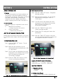
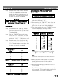
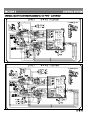
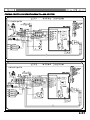
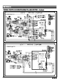
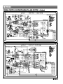
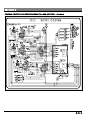
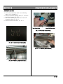
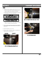
The following error will be displayed on the LED ONLY when the cabinet temperature and overheat protect
sensor are defective or loose connection.
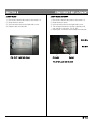
Error Signal
on LED
Er1
Er2
Sensor Type
Description
Cabinet (Room) Defective Sensor
Loose at any connection
Cabinet (Room)
See Pic. 5-3, 5-4, 5-5.
Er3
OHP (Evap)
Er4
OHP (Evap)
Defective Sensor
Loose at any connection
See Pic. 5-3, 5-4, 5-5.
Corrective Action
Replace the sensor
Check all possible loose wire connections.
See Pic. 5-3, 5-4, 5-5.
Replace the sensor
Check all possible loose wire connections.
See Pic. 5-3, 5-4, 5-5.
"OHP" = Overheat Protect = Evap
Sensor Connector Behind the Control Box
Model: ESRF2
[Pic. 5-3: Check Point 1]
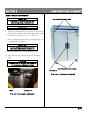
Main Connector Between
Control Box and Condensing Unit
Model: ESRF2
[Pic. 5-4: Check Point 2]
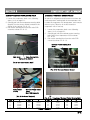
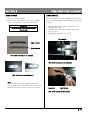
Inside View of Control Box (Power Circuit Board)
Check Loose Connections
Model: ESRF2
[Pic. 5-5: Check Point 3]
5-7-1
M
E
T
S
Y
S
L
A
C
I
R
T
C
E
L
E
6
N
O
I
T
C
E
S
N
O
I
T
A
R
E
P
O
F
O
E
C
N
E
U
Q
E
S
L
A
C
I
R
T
C
E
L
E
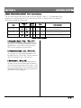
COOLING CYCLE
DEFROST CYCLE
OFF CYCLE
Compressor
ON
OFF
OFF
Condensing Fan Motor
ON
OFF
OFF
Evaporator Fan Motor
ON
OFF
OFF
Evaporator Drain Pan Heater
ON
OFF
OFF
Door Heater
ON
OFF
OFF
Defrost Heater
ON
OFF
OFF
Condensate Pan Heater
ON
OFF
OFF
Light Switch
(Only when the door is open)
ON
OFF
OFF
SYSTEM
[Table 6-1: Electrical Sequence of Operation]
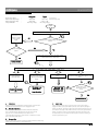
a. Cooling Cycle
With the main ON/OFF switch in the "ON" position
of the control box and red light is on, the current
flows, energizing the compressor, condensing &
evaporator fan motors.
IMPORTANT
There is a 5 seconds delay time on the
compressor for reach-ins that have two or three
condensing units. (Model ESF2, ESWF2, ESRF2,
ESWRF2, ESR3, ESF3, ESRF3)
When the cabinet temperature sensor reads higher
than the setting temperature.
IMPORTANT
After defrost ends, the refrigeration system
begins to operate. But, the evaporator fan motor
will have three (3) minutes of time delay.
IMPORTANT
The defrost cycle is terminated only when
both the temperature and time clock meet
the requirement.
c. OFF Cycle
When the temperature sensing bulb reads the
setting temperature; 35F for refrigerators and
-4 for freezers, it automatically shuts off the
refrigeration system.
IMPORTANT
Temperature differential is +- 3F for
refrigerators and +-2F for freezers. When the
temperature is set at 35F(Refrigerator), it turns
off to the "OFF Cycle" at 32F, and turns on to
the "Cooling Cycle" at 38F.
b. Defrost Cycle
At both automatic & manual defrost time, the PCB
control system de-energizies the evaporator fan
motor, compressor, and condensing fan motor.
The cycle terminates when the evaporator coil
temperature reaches at 61F, and defrost time
clock runs twenty (20) minutes.
6
M
E
T
S
Y
S
N
O
I
T
A
R
E
G
I
R
F
E
R
7
N
O
I
T
C
E
S
S
N
I
H
C
A
E
R
T
H
G
I
R
P
U
F
O
T
I
N
U
G
N
I
S
N
E
D
N
O
C
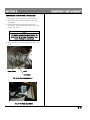
F
O
C
I
T
A
M
E
H
C
S
No
[2] Condenser
Fan Blade
[3] Condenser
Fan Motor
[4] Condenser
Fan Blades Guard
[1] Air Duct
Cover
[5] Condenser Coil
[6] Filter Drier
1
2
3
4
5
6
7
8
9
10
11
12
13
14
15
Part Code
1/3HP CDU 1/2HP CDU
AD01-00
CF02-00
CF01-00
CF03-00
CC02-00
FD01-00
CM03-01
EC02-00
RS01-00
RS02-00
DF01-00
EM06-00
EM01-00
EM03-00
ECA02-02
AD01-00
CF02-00
CF01-00
CF03-00
CC03-00
FD01-00
CM04-00
EC02-00
RS01-00
RS02-00
DF01-00
EM06-00
EM01-00
EM03-00
ECA02-02
(Note: CDU = Condensing Unit)
[7] Compressor
IMPORTANT
Base Panel
Main
Connector
Above part codes are for latest
part revisions at time of
publication. Depending on
unit's serial number, its part
code may differ. Refer to
Section 10.
[12] Fan Motor Bracket
[8] Evap. Coil
[9] Cabinet
Temp. Sensor
[10] Overheat
Protect Sensor
[11] Defrost Heater
[14] Evap.
Fan Blade
[13] Evap.
Fan Motor
[15] Evap.
Drain Cover
1
7
M
E
T
S
Y
S
N
O
I
T
A
R
E
G
I
R
F
E
R
7
N
O
I
T
C
E
S
N
O
I
T
A
M
R
O
F
N
I
R
O
S
S
E
R
P
M
O
C
Products
Solid Door Upright
Reach-Ins
Model
Description
Pressure of
Low(Suction)
Compressor Refrigerant Refrigerant Total Amps
Side During
Compressor Model
(Operation)
HP
Type
(Oz)
Operational
Cycle at Setting
Temp
ESR1
1 Door Refrigerator
FFI-10HAKW
1/3HP
R134A
13.05
3.38
10 to 15 Pounds
ESRH2
2 Half-Door Refrigerator
FFI-10HAKW
1/3HP
R134A
13.05
3.38
10 to 15 Pounds
ESR2
2 Door Refrigerator
FFI-10HAKW
1/3HP
R134A
13.05
4.5
10 to 15 Pounds
ESWR2
2 Wide Door Refrigerator
FFI-10HAKW
1/3HP
R134A
13.05
4.5
10 to 15 Pounds
ESR3
3 Door Refrigerator
FFI-10HAKW
1/3HP X 2
R134A
13.05 X 2
9.49
10 to 15 Pounds
ESF1
1 Door Freezer
NE2134GK
1/2HP
R404A
13.05
8.12
10 to 15 Pounds
ESFH2
2 Half-Door Freezer
NE2134GK
1/2HP
R404A
13.05
8.12
10 to 15 Pounds
ESF2
2 Door Freezer
NE2134GK
1/2HP X 2
R404A
13.05 X 2
15.89
10 to 15 Pounds
ESWF2
2 Wide Door Freezer
NE2134GK
1/2HP X 2
R404A
13.05 X 2
15.89
10 to 15 Pounds
ESF3
3 Door Freezer
NE2134GK (230V)
1/2HP X 3
R404A
13.05 X 2
12.36
10 to 15 Pounds
ESRF2
2 Door Dual Temps
FFI-10HAKW(Ref),
NE2134GK(Fzr)
1/3(Ref),
1/2(Fzr)
R134A(Ref)
13.05(Ref),
,
13.05(Fzr)
R404A(Fzr)
12.08
10 to 15 Pounds
ESWRF2
2 Wide Door Dual Temps
FFI-10HAKW(Ref),
NE2134GK(Fzr)
1/3(Ref),
1/2(Fzr)
R134A(Ref)
13.05(Ref),
,
13.05(Fzr)
R404A(Fzr)
12.08
10 to 15 Pounds
ESWQ3
1 Full & 2 Half-Door Dual
Temps (3/4 Ref & 1/4 Fzr)
FFI-10HAKW(Ref
& Fzr)
1/3 X 2
13.05(Ref),
12.35(Fzr)
12.08
10 to 15 Pounds
ESRF3
3 Door Dual Temps (2/3 Ref & FFI-10HAKW(Ref),
1/3 Fzr)
NE2134GK(Fzr)
R134A(Ref)
13.05(Ref),
,
13.05(Fzr)
R404A(Fzr)
12.62
10 to 15 Pounds
ESGR1
1 Door Refrigerator
FFI-10HAKW
1/3HP
R134A
13.05
4.44
10 to 15 Pounds
ESGR2
2 Door Refrigerator
NE2134GK
1/2HP
R404A
13.05
7.45
10 to 15 Pounds
ESWGR2
2 Wide Door Refrigerator
NE2134GK
1/2HP
R404A
13.05
7.45
10 to 15 Pounds
Glass Door
Merchandisers
EMGR24
1 Door Refrigerator
EMGR48
2 Door Refrigerator (Sliding)
Undercounters
ETR1
1 Door Refrigerator
FFI-7.5HAKW
1/5HP
R134A
8.11
3.04
10 to 15 Pounds
ETR2
2 Door Refrigerator
FGS-70HAW
1/5HP
R134A
8.11
3.52
10 to 15 Pounds
ETF1
1 Door Freezer
FFI-10HAKW
1/3HP
R134A
8.46
4.24
10 to 15 Pounds
ETF2
2 Door Freezer
NE2134GK
1/2HP
R404A
12.34
7.96
10 to 15 Pounds
ETRF2
2 Door Dual Temps
NE2134GK
1/2HP
R404A
12.34
7.96
30 to 35 Pounds
ETRF3
3 Door Dual Temps (2/3 Ref &
1/3 Fzr)
NE2134GK
1/2HP
R404A
12.34
8.12
30 to 35 Pounds
Glass Door Upright
Reach-Ins
1/3(Ref),
1/2(Fzr)
R134A
FFI-10HAKW
1/3HP
R134A
10.23
5.5
10 to 15 Pounds
T6217Z
1/2HP
R134A
17.64
10.4
10 to 15 Pounds
Sandwich Prep Tables EPR1
1 Door Refrigerator
FFI-7.5HAKW
1/5HP
R134A
7.05
3.52
10 to 15 Pounds
EPR2
2 Door Refrigerator
FFI-8.5HAKW
1/4HP
R134A
10.93
3.59
10 to 15 Pounds
EPR3
3 Door Refrigerator
FFI-10HAKW
1/3HP
R134A
9.88
4.06
10 to 15 Pounds
Power of all products above except for model ESF3
115V-60Hz-1Ph
Power of model ESF3
230V-60Hz-1Ph
Note:
The suction pressure of both model ETRF2 & ETRF3 is about 20 pounds higher than other models' pressure during an operation cycle at
setting temperature because these models were designed to be operated with one compressor with two capillary tubes & one solenoid valve.
2
7
T
N
E
M
E
C
A
L
P
E
R
T
N
E
N
O
P
M
O
C
8
N
O
I
T
C
E
S
R
E
V
O
C
N
I
A
R
D
R
O
T
A
R
O
P
A
V
E
1. Disconnect electrical power to the reach-in.
2. Remove five (5) screws to loosen the drain cover
from celling.
3. Loosen the drain cover and pull forward carefully,
Pic. 8-2.
4. Unplug the drain pan wires located next to
condenser coil, Pic. 8-3.
5. Pull the cover, then the wires will come out
through the hole as shown Pic. 8-4.
Ceiling of Cabinet
Back Wall
of Cabinet
Dran Pan Heater
Wire Hole
[Pic. 8-4: Drain Pan Heater Wires]
[Pic. 8-1: Evaporator Drain Cover]
Drain Pan
Drain Hole
[Pic. 8-2: Afrer loosing the Cover]
[Pic. 8-3: Drain Pan Wire Connector]
8-1
T
N
E
M
E
C
A
L
P
E
R
T
N
E
N
O
P
M
O
C
8
N
O
I
T
C
E
S
S
E
D
A
L
B
N
A
F
&
R
O
T
O
M
R
O
T
A
R
O
P
A
V
E
1. Loosen the evaporator drain cover following
steps 1 to 3 on page 8-1.
2. Remove the fan blades from the motor, Pic. 8-5.
3. Remove the motor mounting screws and motor,
Pic. 8-6.
4. Pull out the terminal pins from the main PCB
connector shown Pic. 8-7.
Main PCB
Connector
[Pic.: 8-7: Motor Teminal Pins]
[Pic. 8-5: Fan Blades]
[Pic. 8-6 : Motor and Mounting]
8-2
T
N
E
M
E
C
A
L
P
E
R
T
N
E
N
O
P
M
O
C
8
N
O
I
T
C
E
S
R
E
T
A
E
H
T
S
O
R
F
E
D
1. Loosen the evaporator drain cover following
steps 1 to 3 on page 8-1.
2. Remove the heater holding clips, Pic. 8-8 from
the defrost heater, Pic. 8-9.
3. Pull out the terminal pins from the main PCB
connector shown Pic. 8-10.
4. Remove the defrost heater, Pic. 8-11.
Two Black Wires
Main PCB Connector
[Pic.: 8-10: Defrost Heater Wires]
[Pic. 8-8: Defrost Heater Holding Clip]
[Pic. 8-11: Removing Defrost Heater]
[Pic. 8-9: Removing Clips from Heater]
8-3
T
N
E
M
E
C
A
L
P
E
R
T
N
E
N
O
P
M
O
C
8
N
O
I
T
C
E
S
B
L
U
B
G
N
I
S
N
E
S
T
C
E
T
O
R
P
T
A
E
H
R
E
V
O
B
L
U
B
G
N
I
N
E
S
E
R
U
T
A
R
E
P
M
E
T
T
E
N
I
B
A
C
1. Loosen the evaporator drain cover following
steps 1 to 3 on page 8-1.
2. Carefully pull out the temperature sensing bulb
(purple) from the sensor holder located on the
ceiling of the caninet, Pic. 8-12.
3. Pull out the terminal pins from the main PCB
connector shown Pic. 8-13.
All reach-in refrigerators and freezers must have the
overheat protect sensing bulb in the evaporator coil.
It reads the evaporator coil temperature, and controls
defrost cycle. Failure to do so will cause the
evaporator coil to frost up.
1. Loosen the evaporator drain cover following
steps 1 to 3 on page 8-1.
2. Carefully pull out the overheat protect sensing
bulb (gray) from evaporator coil fins shown
Pic. 8-14.
3. Pull out the terminal pins from the main PCB
connector shown Pic. 8-13.
Overheat Protect Sensing Bulb
(Gray)
Bulb Holder
Temp. Sensing Bulb
Ceiling of the Cabinet
[Pic. 8-12: Temp. Sensing Bulb]
[Pic. 8-14: Overheat Protector Sensor]
Temp. Sensor
(Purple)
Overheat Protect sensor
(Gray)
Main PCB Connector
[Pic. 8-13: Sensor Terminals]
TEMP
-5
0
5
10
15
Ω
71,021
61,520
53,416
46,489
40,552
TEMP
20
25
30
35
40
"A"
[Pic. 8-14-1: Location of Overheat Protect Sensing Bulb]
Ω
TEMP
37,069
45
32,457
50
28,481
55
25,046
60
23,016
65
[Table 8-1: Sensor Ω]
Ω
20,311
17,961
15,914
14,129
13,065
TEMP
70
75
80
85
90
Ω
11,636
10,383
9,282
8,622
7,730
8-4
T
N
E
M
E
C
A
L
P
E
R
T
N
E
N
O
P
M
O
C
8
N
O
I
T
C
E
S
S
E
D
A
L
B
D
N
A
R
O
T
O
M
N
A
F
R
E
S
N
E
D
N
O
C
1. Disconnect electrical power to the reach-in.
2. Open and remove the top grill to reach the
condenser.
3. Unscrew and remove motor mount from
condenser. Then, detatch the motor from the
mount, Pic. 8-15.
NOTE
Unscrew and move the condenser to
the side to split motor mont easily. Be
careful not to damage the copper tube
when moving the condenser.
4. Open the relay box and unplug two wires, Pic.
8-16.
Motor Mount
Motor
Fan Blades
[Pic. 8-15: Condensing Motor]
[Pic. 8-16: Relay Assembly]
8-5
T
N
E
M
E
C
A
L
P
E
R
T
N
E
N
O
P
M
O
C
8
N
O
I
T
C
E
S
T
E
K
S
A
G
R
O
O
D
NOTE
Gasket color has been changed from white to
1. Keep the door open.
2. Firmly grasp the door gasket on the top corners
with both hands.
3. Slowly pull the gasket out of the slotted groove.
Continue until the gasket is removed, Pic. 8-17.
4. To install the replacement door gasket, start
snapping it into the groove at the top of the door.
Begin with two corners. Go evenly from each side
to the middle as shown below Fig 8-1.
5. Work the gasket evely down both sides and then
across the bottom, Fig. 8-1.
CAUTION
Do not stretch or bend the door gasket.
black from the production of November 2005 for
all models. And the surface of the gasket has
several lines to prevent vaccum pressure when
opening door.
NOTE
A special job is required if there is a big gap
between the surface of door frame and the
gasket after installation.Please warm the protion
of the gasket from a distance with using
heatgun. Then foam the gasket by pulling
gently to remove the gap and hold a few seconds
till it foams. A caution is needed, the gasket may
melt if you heat the gasket too much.
[Pic. 8-17: Door Gasket]
1
2
3
4
Reinstall Gasket Starting from
1 to 5
[Fig 8-1: Inside View of Door]
8-6
T
N
E
M
E
C
A
L
P
E
R
T
N
E
N
O
P
M
O
C
8
N
O
I
T
C
E
S
R
O
O
D
1. Release the door spring tension first, Pic. 8-18
a. Insert a small stick into the spring housing; or
use the proper tool that fits in the hole.
b. Remove the tension pin and unload the spring
by backing off on the small stick.
IMPORTANT
Do not release or remove the small stick
after removing the tension pin.
CAUTION
Be careful not to damage the thresds in
the tension pin adjustment holes.
[Pic. 8-19: Remove screws from hinge bracket]
c. Move the tension pin in the hinge one space at
a time to release the spring tension.
2. Remove three top hinge bracket srews. Bottom
hinge bracket does not need to be removed, Pic.
Pic. 8-19.
3. Remove the door, Pic. 8-20.
4. Please make sure that the door is leveled and
balanced after replacement.
Small Stick
Tension Pin
[Pic. 8-20: Remove Door]
[Pic. 8-18: Release Door Spring Tension]
8-7
T
N
E
M
E
C
A
L
P
E
R
T
N
E
N
O
P
M
O
C
8
N
O
I
T
C
E
S
T
N
E
M
T
S
U
J
D
A
N
O
I
S
N
E
T
R
O
O
D
IMPORTANT
The reach-in cabinet must be level
before beginning the adjustment.
Turn Toward the Door Handle
IMPORTANT
Use only hand tools for this procedure.
1. Tighten the spring tension by turning the tension pin
toward to door handle one hole at a time with proper
tools that fit in the hole, Pic. 8-21 & 8-21-1.
2. After you begin feeling tension, stop tightening. Do
not overtighten the spring.
IMPORTANT
Do not release or remove the small
stick after removing the tension pin.
3. Screw the tension pin into a threaded hole.
4. Verify that the door swings freely and closes by
itself.
CAUTION
Be careful not to damage the thresds in
the tension pin adjustment holes.
Turn Toward the Door Handle
Door Handle
[Pic. 8-21-1: Direction of Tightening]
Stick
Tension Pin
[Pic. 8-21: Door Tension Adjustment]
8-8
T
N
E
M
E
C
A
L
P
E
R
T
N
E
N
O
P
M
O
C
8
N
O
I
T
C
E
S
H
C
T
I
W
S
T
H
G
I
L
E
L
D
N
A
H
R
O
O
D
1. Pop out the outer handle.
2. Remove four (4) screws from the inner handle
(Two (2) screws from each top and bottom)
CAUTION
Be sure to put door handle washer
(Pic. 8-23)
The interior light is on and evaporator fan motor(s)
turns off when the light switch releases (when door
is open)
1. Disconnect electrical power to the reach-in.
2. Keep the door open.
3. Carefully pull out the door switch with proper
tool, Pic. 8-21.
4. Unplug the connector, Pic. 8-22
Light Switch
Inner Handle
Outer Handle
[Pic. 8-22: Door Handle for Upright]
[Pic. 8-25: Remove the Light Switch]
[Pic. 8-23: Door Handle Washer]
Note
New recessed door handles applied to all models
from the production of December 2004, serial number
BXXX(X)-0412-0001, except for glass door models.
Connector
Light Switch
[Pic. 8-26: Unplug the Connector]
8-9
T
E
K
C
O
S
B
L
U
B
T
H
G
I
L
B
L
U
B
T
H
G
I
L
Disconnect electrical power to the reach-in.
Keep the door open.
Unscrew and remove the light bulb cover.
Replace with a new bulb.
T
N
E
M
E
C
A
L
P
E
R
T
N
E
N
O
P
M
O
C
8
N
O
I
T
C
E
S
1.
2.
3.
4.
1.
2.
3.
4.
Disconnect electrical power to the reach-in.
Keep the door open.
Unscrew and remove the light bulb cover.
Turn and pull down the socket carefully until
you see the connector, Pic. 8-28.
5. Unplug the connector and install the new part.
White Wire
Red Wire
[Pic. 8-27: Light Bulb Cover]
Connector
Socket
[Pic. 8-28: Light Bulb Socket]
8-10
T
N
E
M
E
C
A
L
P
E
R
T
N
E
N
O
P
M
O
C
8
N
O
I
T
C
E
S
R
E
T
A
E
H
N
A
P
E
T
A
S
N
E
D
N
O
C
C
I
R
T
C
E
L
E
Condensate pan contains water from evaporator
and evaporate it after defrost cycle. The 80 watt
heater operates 24hrs a day.
1. Disconnect electrical power to the reach-in.
2. Reach the connector located at the bottom and
rear of the cabinet, Pic. 8-29.
3. Remove two thumb screws and pull out the pan
from the cabinet, Pic.8-30.
4. Remove four screws from the pan to disassemble
it, Pic. 8-31.
5. Carefully pull out the two terminals from the
conectorand remove the defect adhesive
condensate pan heater, Pic. 8-32 & 8-33.
Insulation
Connector
Electric Condensate Heater
[Pic. 8-31: After Disassembly of Pan]
[Pic. 8-29: Location of Electric Condensate Pan]
Terminals (Red & White)
Connector
[Pic. 8-32: Unplug Terminals]
[Pic. 8-30: Loosen Thumb Screw]
Thumb Screw
[Pic. 8-33: Remove Adhesive Heater]
8-11
T
N
E
M
E
C
A
L
P
E
R
T
N
E
N
O
P
M
O
C
8
N
O
I
T
C
E
S
)
S
(
D
R
A
O
B
T
I
U
C
R
I
C
Y
L
B
M
E
S
S
A
X
O
B
L
O
R
T
N
O
C
1. Disconnect electrical power to the reach-in.
2. Open the top grill to reach the control box,
3. Unplug all connectors on the back of the of
the control box, Pic. 8-34.
1. Disconnect electrical power to the reach-in.
2. Open the top grill to reach the control box,
3. Unplug all connectors at the back of the
control box, Pic. 8-34.
4. Separate the control box assembly from the
IMPORTANT
When you plug in the connectors, make
sure to plug them all the way in. Failure to
do so will cause displaying "Error" on LED.
Please see page 5-7.
cabinet.
5. Remove screws to open the box.
6. The control box includes two boards; "Power
Ciucuit Board"(all relays) and "Main Circuit
Board"(LED & Microchip). Both boards should
be replaced when PCB is Defective.
7. Separate the power circuit board from the main
Connector of
Condensing Unit
Connector of
Condensing Unit
Connector of
Sensor
board by unpluging circuit connectors, "A" in
Pic 8-35.
8. Place a new power circuit board right next to the
old one before the replacement. Pull out one
wire at a time and plug it into the new power
circuit board.
CAUTION
Please pull out one wire at a time
when replacing the power circuit board.
"A"
[Pic. 8-34: Back View of Control Box]
Model ESF2
Wires
[Pic. 8-35: Power Circuit Board]
9. Then replace the main circuit borad.
Note
Depending on a serial number, different
control boards will be provided by the
manufacturer due to an upgrade of the part.
8-12
S
C
I
T
S
O
N
G
A
I
D
9
N
O
I
T
C
E
S
S
C
I
T
S
O
N
G
A
I
D
SERVICE DIAGNOSTIC CHART
Symptom
Unit Does
not run
Cabinet dose not
maintain proper
temperature
Possible Cause
Main power button on control
box is OFF.
Corrective Action
Ppress and hold "POWER ON/OFF"
button on the control box.
Voltage is too low.
Correct the electrical service so
it does not vary more than +/10%.
PCB Control is defective.
Replace the PCB board(s)
Page 8-12
Compressor is defective.
Replace the compressor.
Page 7-2
Relay and/or capacitor is
defective.
Replace the relay and/or capacitor.
Delay time.
It takes about one (1) minute to
run the unit after plug-in.
Page 3-2
Clean the condenser coil.
Page 4
- Refrigerant was overcharged.
Evacuate and recharge the
system with proper amount
of refrigerant.
Page 7
- Condenser fan motor does not
run.
Check motor electrically, replace
if defective.
Page 8-5
- Evaporator fan motor does not
run.
Check motor electrically, replace
if defective.
Page 8-2
- Capillary tube is clogged.
Evacuate and recharge the system.
High pressure in refrigeration
system
- Condenser coil is too dirty.
- Clearance around the unit is
insufficient.
- Condenser air is recirculating
or ambient temperature is above
specification.
System is on "Defrost Cycle".
Reinstall the unit.
References
Page 5-1
Page 3-1
Reinstall the unit.
Page 3-1
During the defrost cycle,
compressor and fan motor of
the evaporator & condensing
do not run. The cycle is terminated
by both temp. (61F) and time(within
20 minutes). Factory defrost setting
is 4 times a day for both freezers
and refrigerators.
Page 5-2
9-1
S
C
I
T
S
O
N
G
A
I
D
9
N
O
I
T
C
E
S
D
E
U
N
I
T
N
O
C
S
C
I
T
S
O
N
G
A
I
D
SERVICE DIAGNOSTIC CHART
Symptom
Cabinet dose not
maintain proper
temperature
(Continued)
Possible Cause
Refrigerant charge is low.
Temp. control system problems.
- Temperature setting is incorrect.
- Control is defective.
Condenser coil is too dirty.
Frozen evaporator coil.
- Air flow is restricted.
(Freezers only)
Corrective Action
Find and repair any refrigeration
leak, replace the filter drier,
evacuate and recharge the system.
Page 7
Reset the desired temperature.
Page 5-1
Replace the circuit board(s).
Page 8-12
Clean the condenser coil.
(Factory recommends condenser
cleaning once a month)
Page 4
Arrange product for proper interior
airflow, check the evaporator coil
for debris.
Page 8-1
- Pressure(Vacuum) relief control
is open.
Check for leaks, repair or replace if
necessary.
- Defrost heater is defective.
Replace the defrost heater.
Page 8-3
- Drain pan heater is defective.
Replace the evaporator drain cover.
Page 8-1
- Insufficient number of defrost
setting.
Defrost the evaporator coil first,
then reset sufficient number of
defrost cycle.
Page 5-3,
5-4, 5-10
- Door is open or gasket is not
sealing properly.
Close door propely, adjust tension
and/or replace gasket if necessary.
Page 8-6,
8-7, 8-8
- Light switch is not properly
pressed.
Adjust location of light switch
bracket.
- Light switch is defective.
Check electrically and replace the
door switch if defective.
Page 8-9
Check for and correct any incorrect
connections.
Check for any loose or bad
connections to the control box.
Page 5-11
Compressor does Wiring problem.
not operate
(Error on LED(s))
Relay is defective.
Check the start relay, replace if
necessary.
Capacitor is defective.
Check the start relay, replace if
necessrry.
9-2
S
C
I
T
S
O
N
G
A
I
D
9
N
O
I
T
C
E
S
D
E
U
N
I
T
N
O
C
S
C
I
T
S
O
N
G
A
I
D
SERVICE DIAGNOSTIC CHART
Symptom
Possible Cause
Door(s) difficult to Pressure(vacuum) relief contol
open
is not functioning.
Wrong installation.
Water is leaking
In the Cabinet.
- Drainage tube is not inserted.
into drain hole properly.
Corrective Action
Check the component, replace if
defective.
Check casters and floor to see if
the unit is properly leveled.
Page 3-1
Open the evaporator drain cover
and check the drainage tube.
Page 8-1
- Evaporator drain cover is broken. Check if there is any crack, replace
if damaged.
Out of the Cabinet.
- Condensate pan heater located
Check electrically first, and replace
at bottom of unit is defective.
the wire type condensate pan heater
if defective.
Noise
In the cabinet.
- Evaporator motor fan damaged
due to ice built on evaporator
coil.
Out of Cabinet.
- Condensing motor fan blades
are broken.
- Condensing motor is defective.
Page 8-1
Page 8-11
Check the defrost heater or control
box to see if they are energizing.
Replace defrost heater or PC board
if defective.
Page 8-2, 8-3
Replace the fan blades.
Pagr 8-5
Check motor, replace if necessary.
Page 8-5
9-3
S
C
I
T
S
O
N
G
A
I
D
9
N
O
I
T
C
E
S
FLOWCHART - POSSIBLE CAUSES
Room temp setting
Nomal room temp range
Nomal evap temp range
Temp differential
Refrigerator
35F
32F to 38F
22F to 28F
3F(6 deg. swing)
:
:
:
:
Freezer
-4F
(Factory Setting)
(When door keeps closed)
-2F to -6F
-12F to -16F
2F (4 deg. swing)
START
Cabinet temp on LED display is higher than normal temp range
Correct all settings
& wait about 10 to
20 min to check
temp on LED
again.
A
NO
Check if all PCB settings are
correct.
NO
Is temp dropping
down?
YES
Check Evap Temp by pressing & holding "HIGH"
arrow button on the control box.
YES
Normal Condition
B
IF "EVAPORATOR TEMPERATURE" is ...
about freezing point, 32F,
or a little bit higher or
lower than 32F
between about 60F and
70F even if room temp on
LED is at normal temp
range.
about same as ambient
temp.
about 5F to 10F degree higher than Normal
Evap temp. Check evap temp again in 10 to
15 min.
D
Ice build-up on evap
coil
C
The system is on
"Defrost Cycle".
Gas Leak, Bad
Compressor, Dirty
Condensing Coil,
NO
If evap temp is at
between the noraml
range
Nomal Condition
YES
Normal Condition
A.
PCB Settings
D.
Defrost Cycle
Please see PCB settings "SECTION 5", different groups of serial numbers
Factory setting for defrost cycle is every 6 hrs from the time when product is
have different settings & modes due to the upgrages of PCB.
plugged in. And the cycle is terminated by the evap sensor (at 61F) & length of
B.
defrost time (20min). The length of defrost time & the interval of defrost cycle can
Evaporator Temperature
All Everest products has a sensor that reads evaporator temperature,
be modified in the setting modes. PCB memorizes the room temp right before the
which is installed between evaporator fins front part of the coil with
defrost cycle begins. Actual room temp displays again when the system meets
grey color wire. It is called "Overheat Protect Sensor" since
two requirements, first is completion of defrost cycle, and second is reaching to
it terminates defrost cycle when it reads over 61F of evaporator coil temp.
the temp right before the cycle.
And it is also called "Evap Sensor".
C.
Receovery Time
It takes a certain time to recover the setting temperature when doors keep being
opened and closed frequentl in a short period of time.
9-4
S
C
I
T
S
O
N
G
A
I
D
9
N
O
I
T
C
E
S
SUMMARY OF DIAGNOSTIC TIPS
Symptom
Possible Causes
Corrective Action
Temperature is
high
Gas leak
Find place of gas leak and repair it
Ice build-up by
a. wrong defrost cycle
or defrost time setting
b. bad defrost heater
c. bad drain pan heater
e. bad fan motor
f. bad door (light) switch
d. bad PCB
b. wrong preservation of
foods in cabinet
c. over charge of refrigerant
Reset the defrost cycle every 6HR w/ 20min. However, this 6HR interval
defrost cycle does not apply to products with air defrost system.
Check if the defrost heater is defective.
Check if drain pan heater if defective.
Check if the evap motor is defective.
Check if the door switch is defective. Evap fan motor stops and cabinet
light is on when the door is open.
Check if the PCB sends power to above parts. Any failure will cause
this ice build-up problem.
Recommend to cover all foods to prevent moisture. If not, then reduce
the interval time of defrost cycle to 5HR or 4HR from 6HR.
Adjust the amount of the refrigerant.
Bad compressor by
a. compressor itself
b. bad start components
c. over charge of refrigerant
Replace the compressor
replace the start coponents (relay, overload, capacitor)
Adjust amount of refrigerant. High pressure in the system causes high
temperature of compressor, which leads the overload to stops the
operation of compressor often.
a. Start capacitor
b. PCB
c. Transformer
Check if the start capacitor is defective.
Check if the PCB is defective.
Check if the transfromer is defective. If it is, then nothing in the system
is working (no display on LED) but light in the cabinet is on.
Bad major
electrical parts
Dirty condensing
coil
Dirty condensing coil will reduce the efficiency of refrigeration operation.
It is required to clean every other month.
Error on LED
a. Er1 or Er2
b. Er3 or Er4
Electric Shock
Leaking water
It is an error by loose connection of cabinet sensor.
Check loose wire connections of the cabinet sensor at all harnesses.
This problem also could be caused by either bad PCB because of
no power transmitting to the sensor or bad cabinet sensor itself.
It is an error by loose connection of evap sensor.
Check loose wire connections of the evap sensor at all harnesses.
This problem also could be caused by either bad PCB because of
no power transmitting to the sensor or bad evap sensor itself.
Electric shortage could be possible caused by shortage at condensate pan
heater harness the most of time. This heater wire is combined with
door heater. Both are working 24Hrs.
a. In the cabinet
b. Out of the cabinet
Check
Check
Check
Check
if
if
if
if
the cabinet is leveled or if there is any crack on plastic cover.
the drain pan heater is defective.
there is any crack on the U-trap.
any object restricts water flow in the pipe or hose to the drain pan.
9-5