1
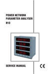
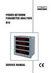
POWER NETWORK PARAMETER ANALYSER N10A SERVICE MANUAL POWER NETWORK PARAMETER ANALYSER - N10A SERVICE MANUAL CONTENTS 1. APPLICATION.................................................................................. 5 2. METER SET..................................................................................... 6 3. INSTALLATION................................................................................ 6 3.1. FITTING.................................................................................... 6 3.2. EXTERNAL CONNECTION DIAGRAMS................................. 8 4. PROGRAMMING........................................................................... 13 4.1. FACEPLATE DESCRIPTION................................................... 13 4.2. N10A OPERATING MODES.................................................... 14 4.2.1 MEASURING MODE....................................................... 15 4.2.1.1. Measurement of voltage and current harmonics......... 16 4.2.2. TIME SETTING MODE - t.............................................. 17 4.2.3. PARAMETER CONFIGURATION MODE - S................. 17 4.2.4. ALARM CONFIGURATION MODE - A........................... 19 4.2.5. PAGE CONFIGURATION MODE - P ............................ 19 5. ERROR CODES............................................................................. 25 6. TECHNICAL DATA........................................................................ 25 7. ORDERING CODES...................................................................... 29 8. MAINTENANCE AND WARRANTY............................................... 30 March 2007 - KZ 1268/06 1. APPLICATIONS The N10A type meter is a programmable digital instrument destined to measure parameters in three-phase three-wire or four-wire power networks, in symmetric and asymmetric systems. The N10A meter is a version of the N10 meter, in which 3 bi-directional analog outputs have been added for customers’ needs. The N10A meter enables the display of measured and calculated quantities (196 in all), the digital transmission of their values and the conversion into three bi-directional analog output signals. Internal current and voltage transformers ensure the galvanic separation of measured channels. The N10A meter ensure the measurement of: RMS voltage and current, active, reactive and apparent power, active reactive and apparent energy, power coefficients, frequency, 15-minute average active power. Voltages and currents are multiplied by voltage and current ratios of measuring transducers what is taking in consideration in calculations and indications of power and energy. The meter shows also the real time. The RS-485 interface enables the communication with the master system. Other communication protocols can be realised through the external converter, e.g. the PD7 type with MODBUS/PROFIBUS. One of the important feature is the possibility to perform the programmed selection of 3 quantities which are converted into bi-directional current signals on 3 analog outputs of the meter. The relay output can serve to signal the overflow of the chosen quantity threshold. Measurements are carried out by the sampling method of the voltage and current signal. The meter is adapted to be fixed in a panel by means of holders. Differences between N10 and N10A meters N10 Analog outputs N10A 1 output 0...20 mA (4...20 mA) 3 outputs ± 5 mA (0...5 mA) accuracy 0.5% accuracy 0.2 % Relay outputs 3 relays 1 relay Impulse passive outputs 1 output none Impulse passive input 1 input none 2. METER SET The set includes: - N10A type meter - service manual - warranty card - holders to fix into a pannel 1 pc. 1 pc. 1 pc. 4 pcs. Additionally for the execution with interface: - service manual of the serial interface - lead of the RS-485 interface - matching resistor - diskette for the WIZPAR program 1 pc. 1 pc. 1 pc. 1 pc. 3. INSTALLATION 3.1. Fitting way The meter is adapted to be mounted by means of holders according fig.1. The meter housing is made of a sell-extinguishing plastics. Housing dimensions are 144x144x77mm. At the rear side of the meter there are terminal strips which enable the connection of 2.5 mm2 external leads. Fig.1 Overall dimensions and fitting way of the N10A meter. 3.2. External connection diagrams Direct measurement in a 3-phase network Half-intermediate measurement in a 3-phase network Fig. 2. Meter connection diagrams in a three-phase network Intermediate measurement using 2-current transformers and 2 or 3 voltage transformers in a 3-phase network Direct measurement in a 4-wire network Half-intermediate measurement in a 4-wire network 10 Fig. 3. Meter connection diagrams in a four-wire network 11 Intermediate measurement using 2-current transformers and 2 or 3 voltage transformers in a 4-wire network NOTICE: To make the IBM PC - N10A meter (RS-485) connection it is recommended to use a double-wire twisted conductor in a shield. The shield should be connected to the earth in one point. The shield is necessary when the environment is very perturbed. Fig. 4. Connecting way of N10A meters with an RS-485 interface. 12 4. PROGRAMMING 4.1. Faceplate description Fig. 5. View of the N10A meter faceplate The N10A meter has 6 keys, four 5-digits display sections, illuminated symbols and parameter units. Values of measured parameters are shown on active pages selected by successive pressures of the key. A page consists of 4 optional quantities chosen from the table 5 and displayed simultaneously on the meter. The page definition is described in the configuration mode P. 13 The assignment of individual keys is as follows: Key It is destined to accept the introduced value during the programmation. It enables the change of pages in the measuring mode. Table 1. 1 2 displacement key 3 increase key 4 decrease key acceptance key displacement key Keys They are destined to change the digit 6 resignation key value on the decimal position during the programmation. They enable the display of suitably minimal and maximal values in the measurement mode. 5 Keys They allow the cursor displacement to successive decimal positions during the programmation and enable the change of display luminosity in the setup procedure. Key This key enables in anytime the resignation of carried out operations. It cancels alarms in measuring mode. 4.2. N10A operating modes The N10A meter has 5 operating modes represented on the table 2. Table 2 MODE NAME CALLING OUT SYMBOL Measuring INPUT OUTPUT default Through entry to another mode t in SETUP procedure , or after the last parameter P in SETUP procedure , or after the last page Parameter configuration S in SETUP procedure , or after the last parameter Alarm configuration and analog outputs A in SETUP procedure , or after the last parameter Time setting Page configuration 14 After its switching on, the meter carries out tests informing by a message: where: r.1.01 - No of the actual program version After tests carrying out, the meter enters into the measuring mode and displays the page positioned before switching off. The entry into another mode is made in the SETUP procedure. In order to enter in the SETUP procedure one should press two keys: during ca 3 seconds, until the audible signal will be switched off. Choose by means of keys the appropriate mode. The active mode t, P, S or A is signalled by the flashing of the suitable symbol. Accept the chosen mode by the key. The return from other modes into the measuring mode is carried out by means of the or key: - after the last parameter (in t, S and A modes), - after the last page (in the P mode). 4.2.1. Measuring mode Values of different quantities are displayed acc. programmed pages by the manufacturer or configurated by the user in the P mode. The change of page is realized by pressing the Key. The sequence of displayed pages is proceeded acc. the table formed in the P mode. The monitoring of maximal or minimal values is realized when pressing respectively the or key. The cancellation of maximal or minimal values is realized when pressing the key during the monitoring of these values, i.e. at first the 15 or key must be pressed and after the key. Alarm is active if it was allocated. One must notice that the alarm do not need to be related to quantities displayed on the page, because a change of page would cause an action on the two-state output. 4.2.1.1. Measurement of voltages and current harmonics The selection of harmonics is made by pressing keys for reviewing current harmonics, or by keys for reviewing voltage harmonics. The selected U1,U2,U3 or I1,I2, I3 quantity is signalled by the flashing of the suitable digit. One must choose by the or key the required quantity and press the key. The following quantities will be displayed: Where: w-n - chosen quantity, e.g. U-1 n-n - harmonic number xxx.x - value of the n-th harmonic The harmonic number up to the 25th harmonic can be changed by means of or keys. The active position is signalled by the cursor. One can return to display the selection of reviewed harmonics by pressing the key. A successive pressure of the key means the return to the measuring mode. For wrong THD indications, successive harmonic values will not be displayed. NOTICE: Indications appear when the parameter 15 will be switch on in the SETUP mode, i.e. the selection of the harmonic measurement and the assumptions concerning their measurements will be fulfilled. 16 4.2.2. Setting time mode - t After the entry into the SETUP procedure one must choose the mode t by pressing the or key and the key. Following values will be displayed: Where: yyyy - year mm - month dd - day By means of keys required values can be set, i.e. the position of the decimal digit can be choosen by the or key, the digit value by the or key. The cursor signals the active position. The set value can be accepted by the key or cancelled by the key and comes back into the measuring mode. causes the setting on the successive parameter. after dd (day), causes the transition to hours and minutes settings. Where: hh - hours mm - mminutes ss - secondes The setting of hours and minutes is similar to the setting of the year, month and day. after min (minutes), causes the memorization of set values and the exit from the mode t. The second counter is not be set but it is zeroed when accepting minutes. This means that in order to obtain an accurate timer setting one must wait till a full minute and then press the key (ENTER). 4.2.3. Parameter configuration mode - S This mode is destined to set meter parameters, input and output signal values. The entry into the parameter configuration mode is protected by the access code if an access code different from zero had been introduced. 17 Item In the case of 0000 code, password inquiry is omitted. If the access code is different from zero, there is the possibility of parameter reviewing, but changes are locked. Values are set in this mode acc. to the table 3. Table 3 Parameter name Designation Range Notice/ description Manufacturer’s values 1 Introduction of access code SECU 0000... 9999 0000 - without code 0000 2 Setting of meter parameters by the manufacturer rESt Y/n n 3 Ratio of current transformer tr_I 1... 20000 4 Ratio of voltage transformer tr_U 1... 4000 5 Quantity on the continuous output Ao_n 0... 34 6 Cancellation of the active energy counter 7 1 1 Quantity code acc. table 5 1 EnP0 Y/n n Cancellation of the reactive energy counter Enq0 Y/n n 8 Cancellation of the apparent energy counter EnS0 Y/n n 9 Cancellation of the 15-minu-tes active power PAV (max. and min. Value) PA_0 Y/n n 10 Averaging time of PAV power PA_t 11 synchronization of the PAV power averaging to the virtual timer PA_S 12 Meter address in the system Adr 1... 247 1 13 Speed of the serial interface bAUd 300,600,.., 19200 19200 14 Interface working mode trYb 0, 1, ...,6 15 Selection of the harmonic measurement Har 0.1 0 16 Change of the access code 0000... 9999 0000 18 15,30,60 min. 15 Y/n 0 -switched off interface 1 - MODBUS ASCII 8N1 2 - MODBUS ASCII 7E1 3 - MODBUS ASCII 7O1 4 - MODBUS RTU 8N2 5 - MODBUS RTU 8E1 6 - MODBUS RTU 8O1 Y 0 In parameters 5, 14 the range 0 means that the appropriate output, or interface switched off. Notations: N - lack of parity (no parity), E - bit checking the even parity, O - bit checking the odd parity. The entry into the procedure causes the setting on the parameter 1 or 2 if the access code is equal 0000. We adjust required values by means of keys, i.e. one can choose the position of the decimal digit by pressing the or key , the digit value by pressing the or key. The active position is signalled by the cursor. One can accept the established value by pressing the key or cancel it by pressing the key and come back to the measuring mode. causes the setting on the successive parameter. after the last parameter, causes the memorization of setting values and the exit from the mode S. Notice: PA_S=Y means that the average power PAV will be brought up to date every 15, 30, or 60 minutes synchronized with the internal virtual timer. PA_S=n means that the average power will be calculated for the last 15, 30, or 60 minutes and brought up to date every 1 second, so-called „moving window”. 4.2.4. Alarm configuration mode - A This mode serves to: - attribute the quantity to alarms, - Set the thresholds setting of alarm switching on and off (also the direction of alarm action). - set the latency of alarm operation, - assign any quantity of the group of 34 parameters (acc. to table 5) of continuous output current signal, - set the changing window of the input signal. 19 Item Table 4 Parameter name Designation Range Notice/ description Quantity code acc. table 5 Manufacturer’s values 1 Two-state output 1 - quantity A1_n 0, 1... 34 2 Two-state output 1 - switch on value A1on 0... 120 [%] 101 3 Two-state output 1 - switch on value A1oF 0... 120 [%] 99 4 Delay in the alarm operation ALdt 0... 100 sec 5 Quantity on the continuous output nr 1 Ao_1 0, 1... 34 6 Lower value of the input range AoL1 -120...0...120 7 Upper value of the input range AoH1 -120...0...120 8 Quantity on the continuous output nr 2 Ao_2 0, 1... 34 9 Lower value of the input range AoL2 -120...0...120 10 Upper value of the input range AoH2 -120...0...120 11 Quantity on the continuous output nr 3 Ao_3 0, 1... 34 12 Lower value of the input range AoL3 -120...0...120 13 Upper value of the input range AoH3 -120...0...120 Delay of alarm switching on Quantity code acc. table 5 2 0 0 (off) - 100 Quantity code acc. table 5 0 (off) - 100 Quantity code acc. table 5 0 (off) - 100 The entry into the mode of alarm setting is not protected by the access code. Alarms are active if they were attributed, i.e. if a measured quantity different than zero (table 5) has been attributed to them. One must notice that alarms concern chosen quantities in the basic configuration mode S and they are not related with quantities displayed on the page. If the quantity value related to the alarm exceeds the declared threshold, the two-state output corresponding to this alarm will be switched on (relay) and the symbol A1 will be lighted. If the quantity value decreases below the alarm threshold, the two-state output is switched off, but the A1 signalling remains until the time of its cancellation by means of the ESC key. 20 The A1on < A1oF setting causes the alarm inverse action, i.e. the output is switched on if the prescribed value decreases below the A1on value and the output is switched off if the value, increases above the A1oF threshold. Analog outputs for parameters accepting values: - positive and negative (table 5), are bi-directional, i.e., for negative parameter values, the analog output signal is also negative, - positive, they are unidirectional, i.e., for positive parameter values, the analog output signal is positive (from the range: 0...+ 5 mA). 4.2.5. Page configuration mode - P This mode is used to select quantities displayed simultaneously on the meter, i.e. to define user’s pages. A list of possible quantities and their codes are inserted in the table 5. Table 5. Code Quantity name 00 01 02 03 04 05 06 07 08 09 10 11 12 13 14 15 16 17 18 19 20 21 22 Symbol Unit Signalling Mark Without quantity - display extinguished Phase 1 voltage U1 (k)V L1 Line L1 curren I1 (k)A L1 Phase L1 active power P1 (M,k)W L1 Phase L1 reactive power Q1 (M,k)V ArL1 Phase L1 apparent power S1 (M,k)VA L1 Phase L1 active power factor (Pf1= P1/ S1) Pf1 Pf L1 Phase L1 t1 factor (t1= Q1/ P1) t1 t L1 Phase L2 voltage U2 (k)V L2 Line L2 current I2 (k)A L2 Phase L2 active power P2 (M,k)W L2 Phase L2 reactive power Q2 (M,k)VAr L2 Phase L2 apparent power S2 (M,k)VA L2 Phase L2 active power factor (Pf2= P2/S2) Pf2 Pf L2 Phase L2 t2 factor (t2= Q2/P2) t2 t L2 Phase 3 voltage U3 (k)V L3 Line L3 current I3 (k)A L3 Phase L3 active power P3 (M,k)W L3 Phase L3 reactive power Q3 (M,k)VAr L3 Phase L3 apparent power S3 (M,k)VA L3 Phase L3 active power factor (Pf3= P3/S3) Pf3 Pf L3 Phase L3 t3 factor (t3= Q3/P3) t3 t L3 Average 3-phase voltage Us (k)V 1,2,3 ////- ////- ////- 21 Table 5. Code Quantity name 23 24 25 26 27 28 29 30 31 32 33 34 35 36 37 38 39 40 41 42 43 44 45 46 47 48 49 50 Signalling Mark Average 3-phase current Is (k)A L1,L2,L3 3-phase active power P (M,k)W L1,L2,L3 3-phase reactive power Q (M,k)VAr L1,L2,L3 3-phase apparent power S (M,k)VA L1,L2,L3 Active power factor (Pf= P/ S) Pf Pf L1,L2,L3 Average 3-phase t factor (t= Q/P) t t L1,L2,L3 Frequency f Hz Voltage between lines L1-L2 U12 (k)V L1,L2 Voltage between lines L2-L3 U23 (k)V L2,L3 Voltage between lines L3-L1 U31 (k)V L3,L1 Average between lines voiltage U123 (k)V L1,L2,L3 15-minutes average active power PAV (M,k)W 1, 2, 3 3-phase active energy EnP (M,k)Wh L1,L2,L3 3-phase reactive energy Enb (M,k)VArh L1,L2,L3 3-phase apparent energy EnS (M,k)VAh L1,L2,L3 Active energy from external counter EnPz (M,k)Wh Reactive energy from external counter Enbz (M,k)VArh Apparent energy from external counter EnSz (M,k)VA Date - day, month Date - year Time - hours, minutes Time - secondes THD of the phase L1 voltage THD U1 V% L1 THD of the phase L2 voltage THD U2 V% L2 THD of the phase L3 voltage THD U3 V% L3 THD of the phase L1 current THD I1 A% L1 THD of the phase L2 current THD I2 A% L2 THD of the phase L3 current THD I3 A% L3 In the case of parameters 45...50, the denominations V and A have got a conventional character distinguishing the given parameter, the basic quantity in %. In order to define pages one must enter into the mode P. 22 Symbol Unit ////- //- By pressing keys set the number nn of user’s pages from the range 00... 20. Accept by the key the chosen mode. If the number of pages is set 00, it means that the user did not decide to define own pages and chose 7 pages programmed by the manufacturer. Manufacturer’s settings are shown below: Page 1 01 08 15 22 U1(k)V U2(k)V U3(k)V Us(k)V Page 2 30 31 32 33 U12(k)V U23(k)V U31(k)V U123(k)V Page 5 24 25 26 27 P (Mk) W Q (Mk) VAr S (Mk) VA Pf 35 36 37 38 Page 3 02 09 16 23 I1(k)A I2(k)A I3(k)A Is (k)A Page 6 EnP (Mk) Wh EnB (Mk) VArh EnS (Mk) VAh f Page 4 03 10 17 24 P1 (Mk)W P2 (Mk)W P3 (Mk)W P (Mk)W Page 7 41 42 43 44 dd.mm yyyy hh.mm ss If a non-zero number of pages has been set then one must define the page con- nn - page number kk - quantity code acc. to the table 5. By pressing display sections. keys, set required quantities on successive The active position is signaled by the cursor. One can accept the established value by the key or cancel it by pressing the key causes the setting on the next parameter or the successive page. after the last page, causes the memorization of pages and the exit from the configuration mode P. 23 Fig.6 N10A meter working modes. 24 5. ERROR CODES During the meter operation, communicates concerning errors can occur. Causes of errors are presented below: Err1 -when the voltage or the current is too low during the measurement: below 7% Un Pfi ,ti and (or) below 2% In f below 0,5% THD Ui, THD Ii, below 1% Un, In or the full interval of the PA_t averaging time is not elapsed yet, Err2 -Lack of possibility to define the maximal or minimal quantity value (lack of current, usually after the meter switching on or the cancellation of extremal values) Lo F - frequency lower than 47 Hz for THD Ui, THD Ii measurements, Hi F - frequency higher than 52 Hz for THD Ui, THD Ii measurements. 6. TECHNICAL DATA Measuring ranges and admissible basic errors are shown on the table 6 Power consumption: - supply circuit - voltage circuit - current circuit 12 VA 0.5 VA 0.1 VA Supply 85...253 V d.c. or a.c., 40...400 Hz Display section: Outputs: - analogue outputs 4 x 5 LED digits, 14 mm high, red or green digits 3 analog outputs: -5... 0...+5 mA accuracy: 0.2% - relay outputs 1 relay voltageless make contacts, load capacity: 250 V a.c./ 0.5 A a.c. Measurement of the harmonics (Up to the 25 th) for currents and voltages THD - Total Harmonic Distortion for currents and voltages 25 Table 6 Measured quantity Range Basic error remarks 100.0 V (Ku=1) 400.0 V (Ku=1) for Ku1... 400.0 kV (0.2% m.v. +0.1% range) Ku = 1...4000 1.000 A (Ki=1) 5.000 A (Ki=1) for Ki1... 20.00 kA (0.2% m.v. +0.1% range) Ki = 1... 20000 P i active power PAV mean active power Active energy EnP, EnPz 0.0... (-)1999.9 W (Wh) for Ku1, Ki1 ...(-)1999.9 MW (MWh) (0.5% m.v. +0.2% range) S i apparent power. Apparent energy EnS, EnSz 0.0... 1999.9 VA (VAh) for Ku1, Ki1 ...1999.9 MVA (MVAh) (0.5% m.v. +0.2% range) Q i reactive power. Reactive energy EnQz 0.0... (-)1999.9 Var (Varh) for Ku1, Ki1 (-)1999.9 MVar (MVarh) (0.5% m.v. +0.2% range) - 1.00 ...0.00 ...1.000 1% m.v. 2c Pf=Power factor=P/S tg i factor (ratio of reactive power to active power) - 99.9....0....99.9 1% m.v. 2c Error in the range: - 99.9...0...99.9 f frequency 15.0... 500.0 Hz 0.5% m.v. 0.2... 200% 0.5% m.v. 2c U i voltage I i current Pf i active power factor THD U, THD I harmonics Where: Ku - voltage transformer ratio Ki - current transformer ratio m.v. - measured value c - less significant display digit THD U - full distorsion factor (by voltage harmonics) THD I - full distorsion factor (by current harmonics) 26 Error in the range: 10...120% U, I 47... 52 Hz Serial interface RS-485 Transmission protocol MODBUS Meter reaction to decays and supply recovery: data and meter state preservation during supply decays, (battery support), work continuation after supply recovery Degree of protection ensured by the housing: - frontal side - rear side IP 40 IP 10 Weight 0.8 kg Overall dimensions 144 144 77 mm Panel cut-out dimensions 138+0.5 138+0.5 Reference conditions and nominal operation conditions: - Input signal: 0...0.01...1.2 In; 0...0.01...1.2 Un, for voltage, current, frequency, power and energy 0...0.02...1.2 In; 0...0.07...1.2 Un, for Pf and t factors, frequency 15...45...65...500 Hz sinusoidal input signal 8% 0.1...1.2 In; 0.1...1.2 Un; 47... 52 Hz, for THDU, THDI and harmonics - power factor - ambient temperature - air humidity - power supply - admissible peak factor: - current - voltage - external magnetic field - short duration overload (5 sec): - voltage inputs - current inputs - working position - warm-up time - 1...0...1 0...23...55°C 25...95% (no condensation) 85... 253 V d.c. or a.c. 40... 400 Hz 2 2 0...40...400 A/m 2 Un (max.1000 V) 10 In optional 5 minutes 27 Additional errors in % of the basic error: - input signal frequency < 50% - ambient temperature changes < 50%/10C Electromagnetic compatibility: - immunity - emission acc. EN 61000-6-2 acc. EN 61000-6-4 Safety requirements: acc. EN 61010-1+A1 - insulation ensured by the housing dual - insulation between circuits basic - installation category III - pollution degree 2 - maximal working voltage relation to earth 600 V a.c. 28 7. ORDERING CODES NETWORK PARAMETER METER - N10A X X X X X XX X Input In current: 1A ( X/1 ) 1 5A ( X/5 ) 2 acc. order * 9 Input phase voltage Un: 100 V 1 400 V acc. order * 2 9 without interface 0 with RS-485 interface 1 red digits 1 green digits 2 85...250 V d.c., a.c., 40...400 Hz 0 acc. order* 9 standard 00 custom-made 99 without additional requirements with a quality inspection certificate 7 acc. customer’s agreement ** X Digital output: Displays: Power supply: Version: Acceptance test: 8 * after agreement with the manufacturer. ** the code numbering will be made by the manufacturer. 29 ORDERING EXAMPLE: code N10A-2-1-1-2-0-00-1-means: input range: 5 A, 100 V, RS-485 interface, green displays, power supply: 85...250 V d.c./a.c., standard version, with a quality inspection certificate. 8. MAINTENANCE AND WARRANTY The N10A meter does not require any periodical maintenance. In case of some incorrect unit operations: 1. In the period of 12 months from the date of purchase: One should take the meter down from the installation and return it to the LUMEL’s Quality Control Dept. If the unit has been used in compliance with the instructions, LUMEL S.A. warrants to repair it free of charge. 2. After the warranty period: One should turn over the meter to repair in a certified service workshop. The disassembling of the housing causes the cancellation of the granted guarantee. Spare parts are available for the period of ten years from the date of purchase. LUMEL S.A. reserves the right to make changes in design and specifications of any products as engineering advances or necessity requires. 30 31 SALES PROGRAM MEASUREMENT DIGITAL and BARGRAPH PANEL METERS CONTROL MEASURING TRANSDUCERS RECORDING ANALOG PANEL METERS (DIN INSTRUMENTS) ANALOG and DIGITAL CLAMP-ON METERS INDUSTRIAL and HOUSEHOLD CONTROLLERS CHART AND PAPERLESS RECORDERS POWER CONTROL UNITS and INVERTERS LARGE SIZE NUMERIC and ALPHANUMERIC DISPLAYS AUTOMOTIVE DASHBOARD INDICATORS ACCESSORIES FOR MEASURING INSTRUMENTS MEASURING SYSTEMS (ENERGY, HEAT, CONTROL) CUSTOM-MADE PRODUCTS WE ALSO OFFER OUR SERVICES IN THE PRODUCTION OF: ALUMINIUM ALLOY PRESSURE CASTINGS PRECISION ENGINEERING AND THERMOPLASTICS PARTS PRESSURE CASTING DIES AND OTHER TOOLS QUALITY PROCEDURES: According to ISO 9001 and ISO 14001 international requirements. All our instruments have CE mark . For more information, please write to or phone our Export Department Lubuskie Zak³ady Aparatów Elektrycznych LUMEL S.A. ul. Sulechowska 1 65-022 Zielona Góra - Poland Tel.: (48-68) 32 95 100 (exchange) Fax: (48-68) 32 95 101 e-mail: [email protected] http://www.lumel.com.pl Export Department: Tel.: (48-68) 32 95 302 or 04 Fax: (48-68) 325 40 91 e-mail: [email protected]