1
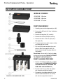
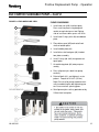
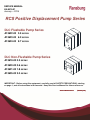
SERVICE MANUAL
LN-9415-01
January— 2015
RCS Positive Displacement Pump Series
DLC Flushable Pump Series
A13622-00 3.5 cc/rev
A13623-00 6.0 cc/rev
A13624-00 9.7 cc/rev
DLC Non-Flushable Pump Series
A13619-00 0.3 cc/rev
A13620-00 0.6 cc/rev
A13621-00 1.8 cc/rev
A13635-00 3.0 cc/rev
IMPORTANT: Before using this equipment, carefully read all SAFETY PRECAUTIONS, starting
on page 1, and all instructions in this manual. Keep this Service Manual for future reference.
Service Manual Price:
$50.00 (U.S.)
Positive Displacement Pump
NOTES
LN-9415-01
Positive Displacement Pump
CONTENTS
SAFETY:
PAGE
1-6
SAFETY PRECAUTIONS.......................................................................................................... 1
HAZARDS / SAFEGUARDS................................................................................................... 2-6
INTRODUCTION:
7
DESCRIPTION.......................................................................................................................... 7
FLOW RATE ACCURACY ........................................................................................................ 7
MODEL OFFERINGS................................................................................................................ 7
FLUID PASSAGES ................................................................................................................... 7
WATER-BASED APPLICATIONS……………………………………………………………………..7
SPECIFICATIONS ................................................................................................................. 7-8
INSTALLATION:
9
GENERAL INFORMATION ....................................................................................................... 9
SYSTEM STARTUP .................................................................................................................. 9
OPERATION:
10
PRINCIPLE OF OPERATION ................................................................................................. 10
SERVICE & PARTS:
11
DISASSEMBLY FLUSHABLE ................................................................................................. 11
REASSEMBLY FLUSHABLE .................................................................................................. 12
PARTS LIST FLUSHABLE PUMP ........................................................................................... 13
DISASSEMBLY NON-FLUSHABLE ........................................................................................ 14
REASSEMBLY NON-FLUSHABLE ......................................................................................... 15
PARTS LIST NON-FLUSHABLE PUMP .................................................................................. 16
MAINTENANCE:
17
CALIBRATION ........................................................................................................................ 17
TROUBLESHOOTING ............................................................................................................ 17
SERVICING ............................................................................................................................ 17
WARRANTY POLICIES:
18
LIMITED APPLIED WARRANTY ............................................................................................. 18
LN-9415-01
Positive Displacement Pump - Safety
SAFETY
SAFETY PRECAUTIONS
Before operating, maintaining or servicing any
Ransburg electrostatic coating system, read
and understand all of the technical and safety
literature for your Ransburg products. This
manual contains information that is important
for you to know and understand. This information relates to USER SAFETY and PREVENTING EQUIPMENT PROBLEMS. To help
you recognize this information, we use the following symbols. Please pay particular attention
to these sections.
A WARNING! states information to alert you
to a situation that might cause serious injury if instructions are not followed.
A CAUTION! states information that tells
how to prevent damage to equipment or
how to avoid a situation that might cause
minor injury.
A NOTE is information relevant to the procedure in progress.
While this manual lists standard specifications
and service procedures, some minor deviations may be found between this literature and
your equipment. Differences in local codes and
plant requirements, material delivery requirements, etc., make such variations inevitable.
Compare this manual with your system installation drawings and appropriate Ransburg
equipment manuals to reconcile such differences.
!
WARNING
The user MUST read and be familiar
with the Safety Section in this manual and
the Ransburg safety literature therein
identified.
This manual MUST be read and thor-
oughly understood by ALL personnel who
operate, clean or maintain this equipment!
Special care should be taken to ensure that
the WARNINGS and safety requirements
for operating and servicing the equipment
are followed. The user should be aware of
and adhere to ALL local building and fire
codes and ordinances as well as NFPA-33
SAFETY STANDARD, LATEST EDITION,
prior to installing, operating, and/or servicing this equipment.
!
WARNING
The hazards shown on the following
pages may occur during the normal use of
this equipment. Please read the hazard
chart beginning on page 2.
Careful study and continued use of this manual
will provide a better understanding of the
equipment and process, resulting in more efficient operation, longer trouble-free service and
faster, easier troubleshooting. If you do not
have the manuals and safety literature for your
Ransburg system,
contact
your local
Ransburg representative or Ransburg.
1
LN-9415-01
Positive Displacement Pump - Safety
AREA
HAZARD
SAFEGUARDS
Tells where hazards may occur.
Tells what the hazard is.
Tells how to avoid the hazard.
Spray Area
Fire Hazard
Fire extinguishing equipment must be present in
the spray area and tested periodically.
Improper or inadequate operation and maintenance proce- Spray areas must be kept clean to prevent the accumulation of combustible residues.
dures will cause a fire hazard.
Protection against inadvertent Smoking must never be allowed in the spray area.
arcing that is capable of causing The high voltage supplied to the atomizer must be
fire or explosion is lost if any turned off prior to cleaning, flushing or maintesafety interlocks are disabled nance.
during operation. Frequent Power Supply or Controller shut- When using solvents for cleaning:
down indicates a problem in the • Those used for equipment flushing should
system requiring correction.
have flash points equal to or higher than those
of the coating material.
•
Those solvents used for general cleaning must
have a flash point at minimum of 5°C (9°F)
greater than the ambient temperature. It is the
end users responsibility to insure this condition
is met.
•
Spray booth ventilation must be kept at the
rates required by NFPA-33, OSHA, country,
and local codes. In addition, ventilation must
be maintained during cleaning operations
using flammable or combustible solvents.
Electrostatic arcing must be prevented. Safe
sparking distance must be maintained between the
parts being coated and the applicator. A distance
of 1 inch for every 10KV of output voltage is required at all times.
Test only in areas free of combustible material.
Testing may require high voltage to be on, but only
as instructed.
Non-factory replacement parts or unauthorized
equipment modifications may cause fire or injury.
If used, the key switch bypass is intended for use
only during setup operations. Production should
never be done with safety interlocks disabled.
Never use equipment intended for use in waterborne installations to spray solvent based materials.
The paint process and equipment should be set up
and operated in accordance with NFPA-33, NEC,
OSHA, local, country, and European Health and
Safety Norms.
LN-9415-01
2
Positive Displacement Pump - Safety
AREA
HAZARD
SAFEGUARDS
Tells where hazards may occur.
Tells what the hazard is.
Tells how to avoid the hazard.
Spray Area
Explosion Hazard
Electrostatic arcing must be prevented. Safe
Improper or inadequate opera- sparking distance must be maintained between the
tion and maintenance proce- parts being coated and the applicator. A distance
dures will cause a fire hazard.
of 1 inch for every 10KV of output voltage is reProtection against inadvertent quired at all times.
arcing that is capable of causing
fire or explosion is lost if any Unless specifically approved for use in hazardous
safety interlocks are disabled locations, all electrical equipment must be located
outside Class I or II, Division 1 or 2 hazardous
during operation.
areas, in accordance with NFPA-33.
Frequent Power Supply or Controller shutdown indicates a Test only in areas free of flammable or combusproblem in the system requiring tible materials.
correction.
The current overload sensitivity (if equipped)
MUST be set as described in the corresponding
section of the equipment manual. Protection
against inadvertent arcing that is capable of
causing fire or explosion is lost if the current overload sensitivity is not properly set. Frequent
power supply shutdown indicates a problem in the
system which requires correction.
Always turn the control panel power off prior to
flushing, cleaning, or working on spray system
equipment.
Before turning high voltage on, make sure no objects are within the safe sparking distance.
Ensure that the control panel is interlocked with the
ventilation system and conveyor in accordance
with NFPA-33, EN 50176.
Have fire extinguishing equipment readily available
and tested periodically.
General Use and
Maintenance
Improper operation or mainte- Personnel must be given training in accordance
nance may create a hazard.
with the requirements of NFPA-33, EN 60079-0.
Personnel must be properly Instructions and safety precautions must be read
trained in the use of this equip- and understood prior to using this equipment.
ment.
Comply with appropriate local, state, and national
codes governing ventilation, fire protection, operation maintenance, and housekeeping. Reference
OSHA, NFPA-33, EN Norms and your insurance
company requirements.
3
LN-9415-01
Positive Displacement Pump - Safety
AREA
HAZARD
SAFEGUARDS
Tells where hazards may occur.
Tells what the hazard is.
Tells how to avoid the hazard.
Spray Area / High Electrical Discharge
Voltage EquipParts being sprayed and operators in the spray
ment
There is a high voltage device area must be properly grounded.
that can induce an electrical
charge on ungrounded objects Parts being sprayed must be supported on conveywhich is capable of igniting coat- ors or hangers that are properly grounded. The
ing materials.
resistance between the part and earth ground must
not exceed 1 meg ohm. (Refer to NFPA-33.)
Inadequate grounding will cause
a spark hazard. A spark can Operators must be grounded. Rubber soled insuignite many coating materials lating shoes should not be worn. Grounding straps
and cause a fire or explosion.
on wrists or legs may be used to assure adequate
ground contact.
Operators must not be wearing or carrying any
ungrounded metal objects.
When using an electrostatic handgun, operators
must assure contact with the handle of the applicator via conductive gloves or gloves with the palm
section cut out.
NOTE: REFER TO NFPA-33 OR SPECIFIC
COUNTRY SAFETY CODES REGARDING
PROPER OPERATOR GROUNDING.
All electrically conductive objects in the spray area,
with the exception of those objects required by the
process to be at high voltage, must be grounded.
Grounded conductive flooring must be provided in
the spray area.
Always turn off the power supply prior to flushing,
cleaning, or working on spray system equipment.
Unless specifically approved for use in hazardous
locations, all electrical equipment must be located
outside Class I or II, Division 1 or 2 hazardous
areas, in accordance with NFPA-33.
LN-9415-01
4
Positive Displacement Pump - Safety
AREA
HAZARD
SAFEGUARDS
Tells where hazards may occur.
Tells what the hazard is.
Tells how to avoid the hazard.
Electrical
Equipment
Electrical Discharge
High voltage equipment is utilized in the process. Arcing in
the vicinity of flammable or
combustible materials may occur. Personnel are exposed to
high voltage during operation
and maintenance.
Unless specifically approved for use in hazardous
locations, the power supply, control cabinet, and all
other electrical equipment must be located outside
Class I or II, Division 1 and 2 hazardous areas in
accordance with NFPA-33 and EN 50176.
Turn the power supply OFF before working on the
Protection against inadvertent equipment.
arcing that may cause a fire or
explosion is lost if safety circuits Test only in areas free of flammable or combustible material.
are disabled during operation.
Frequent power supply shut- Testing may require high voltage to be on, but only
down indicates a problem in the as instructed.
system which requires correcProduction should never be done with the safety
tion.
circuits disabled.
An electrical arc can ignite coating materials and cause a fire or Before turning the high voltage on, make sure no
objects are within the sparking distance.
explosion.
Toxic Substances
Chemical Hazard
Follow the requirements of the Material Safety
Certain materials may be harm- Data Sheet supplied by coating material manufacful if inhaled, or if there is con- turer.
tact with the skin.
Adequate exhaust must be provided to keep the
air free of accumulations of toxic materials.
Use a mask or respirator whenever there is a
chance of inhaling sprayed materials. The mask
must be compatible with the material being
sprayed and its concentration. Equipment must be
as prescribed by an industrial hygienist or safety
expert, and be NIOSH approved.
5
LN-9415-01
Positive Displacement Pump - Safety
AREA
HAZARD
SAFEGUARDS
Tells where hazards may occur.
Tells what the hazard is.
Tells how to avoid the hazard.
Spray Area
Explosion Hazard—
Incompatible Materials
Halogenated hydrocarbon solvents for example: methylene
chloride and 1,1,1, Trichloroethane are not chemically compatible with the aluminum that
might be used in many system
components. The chemical reaction caused by these solvents
reacting with aluminum can become violent and lead to an
equipment explosion.
LN-9415-01
Aluminum is widely used in other spray application
equipment - such as material pumps, regulators,
triggering valves, etc. Halogenated hydrocarbon
solvents must never be used with aluminum equipment during spraying, flushing, or cleaning. Read
the label or data sheet for the material you intend
to spray. If in doubt as to whether or not a coating
or cleaning material is compatible, contact your
coating supplier. Any other type of solvent may be
used with aluminum equipment.
6
Positive Displacement Pump - Introduction
INTRODUCTION
GENERAL DESCRIPTION
These positive displacement pumps have
been developed for precise metering for use
in RCS and RCS-2 systems.
SPECIFICATIONS
Flow Rate:
See Pump Table 1
Accuracy:
95% Efficiency based on
testing with Wet-Sol Material @ 50 RPM with 1 bar
differential on Pump Inlet /
Outlet.
(System Dependent )
FLOW RATE ACCURACY
Flow rate accuracies of ± 5% can be expected
with use of these positive displacement
pumps.
Working Pressure:
See Pump Table 1
CURRENT MODELS
OFFERED
Temperature:
See Pump Table 1
Flushable Version:
A13622-00 3.5 cc/rev
A13623-00 6.0 cc/rev
A13624-00 9.7 cc/rev
Materials:
Non-Flushable Version:
A13619-00 0.3 cc/rev
A13620-00 0.6 cc/rev
A13621-00 1.8 cc/rev
A13635-00 3.0 cc/rev
FLUID PASSAGES
Both pump versions employ a DLC (Diamond
Like Coating) for extended wear. The flushable pump series (when equipped with a 22337 by-pass valve) provides faster color
changes and minimizes solvent usage.
Body:
See Pump Table 1
Gears:
See Pump Table 1
Bushings:
See Pump Table 1
Shafts:
See Pump Table 1
Seal:
22-315 (Flushable)
22-383 (Non-Flushable)
Filtration:
100 Mesh (maximum)
Connections:
22-935-1 Color
(Flushable Manifold)
22-872 Catalyst
(Non-Flushable Manifolds)
WATER-BASED APPLICATIONS
The DLC pumps can be used in waterborne
applications overall. It is highly recommended
that water-based materials be submitted to
our lab for evaluation to determine material
compatibility with these pumps.
7
Weight:
See Pump Table 1
LN-9415-01
Positive Displacement Pump - Introduction
INTRODUCTION
RCS GEAR PUMP TABLE 1
- SPECIFICATIONS -
A13619
A13620
A13621
A13635
A13622
A13623
A13624
Displacement (cc/rev)
0.3
0.6
1.8
3.0
3.5
6.0
9.7
Weight of Pump (lbs.)
Base Pump Material
3.6
440B
3.8
440B
3.8
440B
4.4
440B
6.4
440B
6.6
440B
8.2
440B
Pump Bushing Material
440B
440B
440B
440B
440B
440B
440B
Shaft & Gear Material
440B
440B
440B
440B
440B
440B
440B
Hardness DLC (Vickers)
2500
2500
2500
2500
2500
2500
2500
Working Pressure max
(PSI)
300
300
300
300
300
300
300
Input pressure max (PSI)
145
145
145
145
145
145
145
Part No.
Working temp. (°C)
-20 to 150° -20 to 150° -20 to 150° -20 to 150° -20 to 150° -20 to 150° -20 to 150°
Pump Style
NonNonNonNonFlushable Flushable Flushable
Flushable Flushable Flushable Flushable
(Resin)
(Resin)
(Resin)
(Catalyst) (Catalyst) (Catalyst) (Catalyst)
LN-9415-01
8
Positive Displacement Pump - Installation
INSTALLATION
GENERAL INFORMATION
The displacement pump (Gear Pump) is used on the RCS and RCS-2 systems. Pumps are
mounting directly to either a resin manifold (for the flushable pump unit) or a catalyst
manifold (for the non-flushable pump). Typical torque applied to the mounting bolts should
not exceed 17 lb-ft (23 N-m). Excessive torque can lead to pump seizure and internal
pump damage. Always follow specified torque settings.
RCS RESIN PUMP MOUNTED ILLUSTRATION
- MAX TORQUE FOR MOUNTING BOLTS: 17 LB-FT ( 23 N-m) -
Both Series of Gear Pumps
Require Four Bolts:
•
Two SHCS (longest) bolts
use bushing A12304-XX
•
Two bolts (shorter) are
standard SHCS
CAREFULLY TIGHTEN BOLTS DOWN IN
AN “X” PATTERN AS SHOWN IN ABOVE
ILLUSTRATION
9
Note:
System Start-Up
TORQUE REQUIREMENTS AND TIGHTENING
PROCEDURES HAVE THE SAME TORQUE
SPECIFICATIONS FOR BOTH CATALYST
(NON-FLUSHABLE) AND RESIN (FLUSHABLE)
PUMPS.
Pump assemblies are shipped with Wet-sol material to protect pump inner workings. To remove Wetsol, flush and purge the system with solvent as
needed.
LN-9415-01
Positive Displacement Pump - Operation
OPERATION
PRINCIPLE OF OPERATION
The external gear pump is a positive displacement (PD) type of pump generally
used for the transfer and metering of liquids. The gear pump is a precision machine
with extremely tight fits and tolerances, and
is capable of working under high differential
pressures.
Typically there is a drive gear driven by a
motor that rotates an idler gear in the
opposite direction. When the gears rotate,
the liquid, which is trapped in the gear teeth
spaces between the housing bore and the
outside of the gears, is transferred from the
inlet side of the pump to the outlet side. The
pumped liquid moves around the outside of
the gears and not between the gears. The
rotating gears continue to deliver a fresh
supply of liquid from the suction (inlet) side
of the pump to the discharge (outlet) side of
the pump, with virtually no pulsations. The
meshing of the gears on the discharge side
of the pump forces the liquid out of the
pump and into the discharge port.
Flow rate through the pump is controlled
simply by varying the RPM of the motor
driving the pump. On RCS and RCS-2
Systems, it is recommended that the RPM
of the pump not be allowed to exceed 150
RPM’s.
If the inlet pressure of the pump is too low,
the pump will be starved for material and
will cavitate, resulting in lower flows than
expected. Additionally, if the outbound
pressure is significantly higher than the inlet
pressure, the gears will slip by the material,
also causing the flow to be less than expected.
On the other hand, if the inlet pressure is
too high (especially at low viscosities),
material can “blow by” the gears in the
meter and the resultant flow will be higher
than expected.
Positive displacement gear pumps are most
accurate when the pressure across the
pump (known as differential pressure) is
minimized. That is, if the inlet pressure can
be maintained at a pressure that is very
close to the outlet pressure, the most
accuracy will be realized. The RCS and
RCS-2 Systems have the ability to control
the inlet pressure automatically based on
the value of the outlet pressure. This,
however, is an optional feature. If you are
interested in enabling this feature on your
RCS or RCS-2 System, contact your
Ransburg representative.
The accuracy of the gear pump is directly
affected by both the viscosity of the material
being pumped and the differential pressure
across the pump.
If the material is too thin (e.g. viscosities
less than 30 centipoise), it will not be
properly metered by the pump and inaccurate flow rates will result.
LN-9415-01
10
Positive Displacement Pump - Operation
DLC COATED FLUSHABLE PUMP
10
MODELS COVERED:
A13622-00 3.5 cc/rev
A13623-00 6.0 cc/rev
A13624-00 9.7 cc/rev
PUMP DISASSEMBLY
1. Carefully press out the alignment pins (#2).
2. Unscrew the M6 bolts (#1) from the bottom
of the pump.
3. Remove the top plate (#7), carefully.
4. Remove the center plate (#4) carefully.
5. Remove the drive shaft with gear (#6) &
idler gear (#5).
6. To remove gear from shaft, remove circlips
and slide gear off of shaft.
7. Pull seal (#10) from front plate (use seal
puller or drive from opposite side). Be
careful not to damage the pump bore during removal.
Please Note: Driven shaft is fixed in the body
and cannot be removed. (DO NOT ATTEMPT
TO REMOVE THE FIXED SHAFT!)
PUMP CLEANING PROCESS
1. All parts should be cleaned with a suitable
cleaning agent. (CLEANING WITH ABRASIVE MATERIALS WILL DAMAGE THE
PUMP AND VOID WARRANTY!)
2. Discard used O-rings (#10) and replace
with new ones during reassembly.
3.
FIGURE 1-3 EXPLODED PUMP VIEW
11
Pump plates should be dried with lint free
towel and lubricated before reassembly
with wet-sol or equivalent material.
LN-9415-01
Positive Displacement Pump - Operation
DLC COATED FLUSHABLE PUMP—Cont’d
FIGURE 1-4 EXPLODED PUMP VIEW
10
PUMP REASSEMBLY
1. Install new seal (#10) into front plate.
Press seal into place using deep well
socket or equivalent press tool. Spring
side of seal faces down, press until flush.
2. Install new O-rings (#8 & #9) onto bottom
plate.
3. Place driven gear (#5) back onto fixed
shaft on bottom plate.
4. Install middle plate (#4).
5. Install drive shaft and gear (#6) into bottom plate assembly.
6. Install O-rings (#8 & #9) into grooves on
top of plate.
7. Assemble top plate (#3) onto pump assembly
8. Press alignment pins back into pump
carefully.
9. Reinstall bolts (#1), and tighten in a star
pattern. Torque to 13 Lb-Ft (15 Nm).
Note: Drive shaft of pump should be manually turned during the bolt tightening process to assure free spinning gears.
10. Set alignment pins so they protrude out by
2.5mm from front plate.
LN-9415-01
12
Positive Displacement Pump - Operation
DLC Coated Flushable Pump—Cont’d
FLUSHABLE PUMP PARTS LISTING
SEE FIGURE 1-4 EXPLODED PUMP VIEW
ITEM
QTY
PART NUMBER
DESCRIPTION
COMMENTS
1
6
----------------
M6 BOLT
SOURCE LOCAL
2
2
----------------
PIN, ALIGNMENT
N/A
3
1
----------------
PLATE, BOTTOM
N/A
4
1
PLATE,CENTER
SEE KIT CHART “B” BELOW
5
1
GEAR, DRIVEN
SEE KIT CHART “B” BELOW
6
1
GEAR
SEE KIT CHART “B” BELOW
7
1
----------------
KEYWAY
N/A
8
2
A13790-00*
O-RING
*INCLUDED IN A13790 KIT
9
2
A13790-00*
O-RING
*INCLUDED IN A13790 KIT
10
1
22-315*
SEAL,RADIAL
*INCLUDED IN A13790 KIT
FLUSHABLE PUMP KIT GEARS & SPACER PLATE
CHART “B” FIELD PUMP REPAIR KIT (HARD PARTS)
13
PUMP KIT #
DESCRPTION
USED ON PUMP #
SIZE CC’S
A13792-05
KIT, GEARS & SPACER PLATE 3.5 CC DLC PUMP
A13622-00
3.5
A13792-06
KIT, GEARS & SPACER PLATE 6.0 CC DLC PUMP
A13623-00
6.0
A13792-07
KIT, GEARS & SPACER PLATE 9.7 CC DLC PUMP
A13624-00
9.7
LN-9415-01
Positive Displacement Pump - Operation
DLC COATED NON-FLUSHABLE PUMP SERVICE
MODELS COVERED:
15
A13619-00 .3 cc/rev A13621-00 1.8 cc/rev
A13620-00 .6 cc/rev A13635-00 3.0 cc/rev
PUMP DISASSEMBLY
1. Carefully press out the alignment pins.
2. Unscrew item #1 (the 6 M6 bolts) from the
bottom of the pump.
3. Remove the top plate (#14) carefully with
drive shaft and gear.
4. To remove the drive shaft (#8) with gear
(#5), remove circlip (#6), slide gear off,
remove key, then remove second circlip.
Shaft will slide out though shaft seal (#15).
Note: it will only slide out in one direction.
5. Remove the center plate (#9) carefully.
6. Slide drive gear off of shaft.
7. Pull seal (#15) from front plate (use seal
puller or drive from opposite side). Be
careful not to damage the pump bore during removal.
Please Note: Driven shaft (#4) is fixed in the
body and cannot be removed. (DO NOT ATTEMPT TO REMOVE THE FIXED SHAFT!)
PUMP CLEANING PROCESS
1. All parts should be cleaned with a suitable
cleaning agent. (CLEANING WITH
ABRASIVE MATERIALS WILL DAMAGE
THE PUMP AND VOID WARRANTY!)
2. Discard all used O-rings (#10) and replace
during reassembly.
FIGURE 1-1 EXPLODED PUMP VIEW
LN-9415-01
3.
Pump plates should be dried with lint free
towel and lubricated before reassembly
with wet-sol or equivalent material.
14
Positive Displacement Pump - Operation
DLC COATED NON-FLUSHABLE PUMP—Cont’d
PUMP REASSEMBLY
FIGURE 1-2 EXPLODED PUMP VIEW
1. Slide new seal (#15) onto drive shaft approximately to the position that balloon 8 points to in figure at
left. The spring side of the seal points down.
8
2. Bring shaft with seal down onto front plate.
3. Press seal into place using deep well socket or
equivalent press tool. Allow shaft to move with
seal while pressing into place. A 0.002” feeler
gauge may be used as a guide to get seal started
into housing.
15
4. Install circlip on drive shaft closest to front plate.
14
5. Install key (#7). Slide on drive gear (#5) and install
second circlip.
6. Install a new O-ring (#10) on bottom plate and top
plate in appropriate O-ring grooves.
10
7. Place driven gear back onto fixed shaft on bottom
plate.
9
8. Install middle plate (#9).
9. Assemble top plate (#14) onto pump.
7
10. Press alignment pins back into pump carefully.
5
6
4
Do Not Remove!
11. Reinstall bolts (#1). Tighten them in a star pattern
and torque them to13 Lb-Ft (15 Nm). Note: Drive
shaft of pump should be manually turned during
the bolt tightening process to assure free spinning
gears.
12. Set alignment pins so they protrude out by 2.5mm
2
from front plate.
1
15
LN-9415-01
Positive Displacement Pump - Operation
DLC COATED NON-FLUSHABLE PUMP—Cont’d
NON-FLUSHABLE PUMP PARTS LISTING
SEE FIGURE 1-2 EXPLODED PUMP VIEW
ITEM
QTY
PART NUMBER
DESCRIPTION
COMMENTS
1
6
----------------
M6 BOLT
SOURCE LOCAL
2
2
----------------
PIN, ALIGNMENT
N/A
3
1
----------------
PLATE, BOTTOM
N/A
4
----
-----------------
---------------------
5
2
A13792-XX
GEAR
SEE KIT CHART “A” BELOW
6
2
A13792-XX
CIRCLIP
SEE KIT CHART ‘”A” BELOW
7
1
----------------
KEYWAY
N/A
8
1
----------------
SHAFT,MAIN
N/A
9
1
A13792-XX
PLATE,CENTER
SEE KIT CHART “A” BELOW
10
2
A13791-00*
O-RING
*INCLUDED IN A13791 KIT
11
----
----------------
---------------------
12
----
----------------
---------------------
13
----
----------------
---------------------
14
----
----------------
PLATE, TOP
N/A
15
1
22-383*
SEAL,RADIAL
*INCLUDED IN A13791 KIT
NON-FLUSHABLE PUMP KIT GEARS & SPACER PLATE
CHART “A” FIELD PUMP REPAIR KIT (HARD PARTS)
PUMP KIT #
DESCRPTION
A13792-01
KIT, GEARS & SPACER PLATE 0.3 CC DLC PUMP
A13619-00
0.3
A13792-02
KIT, GEARS & SPACER PLATE 0.6 CC DLC PUMP
A13620-00
0.6
A13792-03
KIT, GEARS & SPACER PLATE 1.8 CC DLC PUMP
A13621-00
1.8
A13792-04
KIT, GEARS & SPACER PLATE 3.0 CC DLC PUMP
A13635-00
3.0
LN-9415-01
USED ON PUMP #
SIZE CC’S
16
Positive Displacement Pump - Maintenance
MAINTENANCE
CALIBRATION
The calibration value will vary based on
viscosity, flow rate, temperature, and other
factors. Refer to appropriate associated
equipment for calibration procedure.
TROUBLESHOOTING
Gear Pump problems can be caused by
improperly filtered fluid. Particulates in the
fluid can cause gear binding. Maintain the fluid
filters according to the instructions from the
filter manufacturer. If repeated disassembly
and cleaning for removal of solids and particulates occurs, inspect the entire fluid supply
system and evaluate the system cleaning
cycle.
SERVICING
Depressurize the gear pumps before attempting to remove from manifold. Remove the gear
pump for service to a suitable clean area to
perform maintenance. Using a hex key
wrench, remove all 4 bolts. See pages 11-15
for teardown and reassembly procedures for
both series of gear pumps.
17
LN-9415-01
Positive Displacement Pump - Warranty Policies
WARRANTY POLICIES
LIMITED WARRANTY
Ransburg will replace or repair without charge
any part and/or equipment that falls within the
specified time (see below) because of faulty
workmanship or material, provided that the
equipment has been used and maintained in
accordance with Ransburg's written safety and
operating instructions, and has been used
under normal operating conditions. Normal
wear items are excluded.
THE USE OF OTHER THAN RANSBURG
APPROVED PARTS, VOID ALL WARRANTIES.
SPARE PARTS: One hundred and eighty (180)
days from date of purchase, except for rebuilt
parts (any part number ending in "R") for which
the warranty period is ninety (90) days.
EQUIPMENT: When purchased as a complete
unit, (i.e., guns, power supplies, control units,
etc.), is one (1) year from date of purchase.
RANSBURG'S
ONLY
OBLIGATION
UNDER THIS WARRANTY IS TO REPLACE PARTS THAT HAVE FAILED
BECAUSE OF FAULTY WORKMANSHIP
OR MATER-IALS. THERE ARE NO
IMPLIED WAR-RANTIES NOR WARRANTIES OF EITHER MERCHANTABILITY OR
FITNESS FOR A PARTICULAR PURPOSE.
RANSBURG ASSUMES NO LIABILITY
FOR INJURY, DAMAGE TO PROPERTY
OR FOR CONSEQUENTIAL DAMAGES
FOR LOSS OF GOODWILL OR PRODUCTION OR INCOME, WHICH RESULT FROM
USE OR MISUSE OF THE EQUIPMENT BY
PURCHASER OR OTHERS.
EXCLUSIONS:
If, in Ransburg's opinion the warranty item in
question, or other items damaged by this
part was improperly installed, operated or
maintained, Ransburg will assume no
responsibility for repair or replacement of the
item or items. The purchaser, therefore will
assume all responsibility for any cost of
repair or replacement and service related
costs if applicable.
WRAPPING THE APPLICATOR, ASSOCIATED VALVES AND TUBING, AND
SUPPORTING HARDWARE IN PLASTIC,
SHRINK-WRAP, OR ANY OTHER NONAPPROVED COVERING, WILL VOID THIS
WARRANTY.
LN-9415-01
18
Manufacturing
1910 North Wayne Street
Angola, Indiana 46703-9100
Telephone: 260-665-8800
Fax: 260-665-8516
Technical Service — Assistance
320 Philips Ave.
Toledo, Ohio 43612-1493
Telephone (toll free): 800-233-3366
Fax: 419-470-2233
www.ransburg.com
Technical Support Representative will direct you to the appropriate telephone number for ordering Spare Parts.
© 2015 Finishing Brands, Americas..
Models and specifications subject to change without notice.
Form No. LN-9415-01
Litho in U.S.A.
01/15