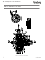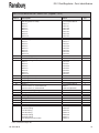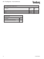
1
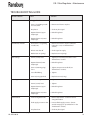
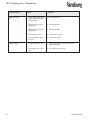
SERVICE MANUAL
LN-9223-00.10
(Replaces LN-9223-00.9)
January - 2013
DR-1 FLUID REGULATOR
MODEL: 74151
IMPORTANT: Before using this equipment, carefully
read SAFETY PRECAUTIONS, starting on page 1, and all
instructions in this manual. Keep this Service Manual
for future reference.
Service Manual Price: $20.00 (U.S.)
NOTE:
This manual has been changed from revision LN-9223-00.9 to revision LN-9223-00.10. Reasons for this change are noted under “Manual Change Summary” inside the back cover of this manual.
DR-1 Fluid Regulator - Contents
CONTENTS
SAFETY:
PAGE
1-4
SAFETY PRECAUTIONS............................................................................................................
HAZARDS / SAFEGUARDS........................................................................................................
1
2-4
INTRODUCTION:
5-6
FEATURES..................................................................................................................................
SPECIFICATIONS.......................................................................................................................
DR-1 FLOW VS SIGNAL PRESSURE........................................................................................
5
5
6
OPERATION:
7-8
OPERATION................................................................................................................................
7
MAINTENANCE:
9-16
TOOLS REQUIRED.....................................................................................................................
PRELIMINARY PROCEDURES..................................................................................................
DISASSEMBLY PROCEDURES.................................................................................................
REGULATOR CROSS-SECTIONAL VIEW................................................................................
ASSEMBLY PROCEDURES.......................................................................................................
TEST PROCEDURES.................................................................................................................
PREVENTIVE MAINTENANCE...................................................................................................
TROUBLESHOOTING GUIDE....................................................................................................
9
9
9-10
11
12-13
13
13
14-15
PARTS IDENTIFICATION:
17-20
REGULATOR CROSS-SECTIONAL VIEW / PARTS LIST.......................................................
RECOMMENDED SPARE PARTS.............................................................................................
SERVICE KITS............................................................................................................................
17-18
19
19
WARRANTY POLICIES:
21
LIMITED WARRANTY.................................................................................................................
21
DR-1 Fluid Regulator - Safety
SAFETY
SAFETY PRECAUTIONS
Before operating, maintaining or servicing any Ransburg coating system, read and understand all of the
technical and safety literature for your Ransburg
products. This manual contains information that
is important for you to know and understand. This
information relates to USER SAFETY and PREVENTING
EQUIPMENT PROBLEMS. To help you recognize this
information, we use the following symbols. Please
pay particular attention to these sections.
A WARNING! states information to alert you to a situation that might cause serious injury if instructions
are not followed.
A CAUTION! states information that tells how to
prevent damage to equipment or how to avoid a
situation that might cause minor injury.
!
WARNING
> The user MUST read and be familiar with
the Safety Section in this manual and the
Ransburg safety literature therein identified.
> This manual MUST be read and thoroughly
understood by ALL personnel who operate, clean
or maintain this equipment! Special care should
be taken to ensure that the WARNINGS and safety
requirements for operating and servicing the
equipment are followed. The user should be
aware of and adhere to ALL local building and
fire codes and ordinances as well as NFPA-33
SAFETY STANDARD, prior to installing, operating,
and/or servicing this equipment.
A NOTE is information relevant to the procedure in
progress.
While this manual lists standard specifications and
service procedures, some minor deviations may be
found between this literature and your equipment.
Differences in local codes and plant requirements,
material delivery requirements, etc., make such
variations inevitable. Compare this manual with
your system installation drawings and appropriate
Ransburg equipment manuals to reconcile such
differences.
!
WARNING
> The hazards shown on the following
page may occur during the normal use of
this equipment. Please read the hazard chart
beginning on page 2.
Careful study and continued use of this manual will
provide a better understanding of the equipment and
process, resulting in more efficient operation, longer
trouble-free service and faster, easier troubleshooting.
If you do not have the manuals and safety literature
for your Ransburg system, contact your local Ransburg
representative or Ransburg.
1
LN-9223-00.10
DR-1 Fluid Regulator - Safety
AREA
HAZARD
SAFEGUARDS
Tells where hazards
Tells what the hazard is.
Tells how to avoid the hazard.
Fire Hazard
Fire extinguishing equipment must be present in the
spray area and tested periodically.
may occur.
Spray Area
Improper or inadequate operation
and maintenance procedures will Spray areas must be kept clean to prevent the accumulacause a fire hazard.
tion of combustible residues.
Protection against inadvertent arcing that is capable of causing fire or
explosion is lost if any safety interlocks are disabled during operation.
Frequent power supply shutdown
indicates a problem in the system
requiring correction.
Smoking must never be allowed in the spray area.
The high voltage supplied to the atomizer must be
turned off prior to cleaning, flushing or maintenance.
When using solvents for cleaning:
Those used for equipment flushing should have flash
points equal to or higher than those of the coating
material.
Those used for general cleaning must have flash points
above 100oF (37.8oC).
Spray booth ventilation must be kept at the rates required by NFPA-33, OSHA, and local codes. In addition,
ventilation must be maintained during cleaning operations using flammable or combustible solvents.
Electrostatic arcing must be prevented.
Test only in areas free of combustible material.
Testing may require high voltage to be on, but only as
instructed.
Non-factory replacement parts or unauthorized equipment modifications may cause fire or injury.
If used, the key switch bypass is intended for use only
during setup operations. Production should never be
done with safety interlocks disabled.
Never use equipment intended for use in waterborne
installations to spray solvent based materials.
The paint process and equipment should be set up and
operated in accordance with NFPA-33, NEC, and OSHA
requirements.
LN-9223-00.10
2
DR-1 Fluid Regulator - Safety
AREA
HAZARD
SAFEGUARDS
Tells where hazards
Tells what the hazard is.
Tells how to avoid the hazard.
may occur.
General Use and
Maintenance
Improper operation or maintenance Personnel must be given training in accordance with
may create a hazard.
the requirements of NFPA-33.
Personnel must be properly trained Instructions and safety precautions must be read and
in the use of this equipment.
understood prior to using this equipment.
Comply with appropriate local, state, and national codes
governing ventilation, fire protection, operation maintenance, and housekeeping. Reference OSHA, NFPA-33,
and your insurance company requirements.
Electrical
Equipment
High voltage equipment is utilized.
Arcing in areas of flammable or
combustible materials may occur.
Personnel are exposed to high
voltage during operation and
maintenance.
The power supply, optional remove control cabinet,
and all other electrical equipment must be located
outside Class I or II, Division 1 and 2 hazardous areas.
Refer to NFPA-33.
Turn the power supply OFF before working on the
equipment.
Protection against inadvertent arcing that may cause a fire or explosion Test only in areas free of flammable or combustible
is lost if safety circuits are disabled material.
during operation.
Testing may require high voltage to be on, but only as
Frequent power supply shutdown instructed.
indicates a problem in the system
which requires correction.
Production should never be done with the safety circuits disabled.
An electrical arc can ignite coating
materials and cause a fire or explo- Before turning the high voltage on, make sure no objects
are within the sparking distance.
sion.
Explosion
Hazard/
Incompatible
Materials
3
Halogenated hydrocarbon solvents
for example: methylene chloride
and 1,1,1,-Trichloroethane are not
chemically compatible with the
aluminum that might be used in
many system components. The
chemical reaction caused by these
solvents reacting with aluminum
can become violent and lead to an
equipment explosion.
Aluminum is widely used in other spray application
equipment - such as material pumps, regulators, triggering valves, etc. Halogenated hydrocarbon solvents
must never be used with aluminum equipment during
spraying, flushing, or cleaning. Read the label or data
sheet for the material you intend to spray. If in doubt as
to whether or not a coating or cleaning material is compatible, contact your material supplier. Any other type
of solvent may be used with aluminum equipment.
LN-9223-00.10
DR-1 Fluid Regulator - Safety
AREA
HAZARD
SAFEGUARDS
Tells where hazards
Tells what the hazard is.
Tells how to avoid the hazard.
may occur.
Toxic Substances
Certain material may be harmful if Follow the requirements of the Material Safety Data
inhaled, or if there is contact with Sheet supplied by coating material manufacturer.
the skin.
Adequate exhaust must be provided to keep the air free
of accumulations of toxic materials.
Use a mask or respirator whenever there is a chance of
inhaling sprayed materials. The mask must be compatible with the material being sprayed and its concentration. Equipment must be as prescribed by an industrial
hygienist or safety expert, and be NIOSH approved.
Spray Area /
High Voltage
Equipment
This is a high voltage device that Parts being sprayed must be supported on conveyors
can produce electrical arcs capable or hangers and be grounded. The resistance between
of igniting coating materials.
the part and ground must not exceed 1 megohm.
(Reference NFPA-33.)
A safe distance must be maintained between the parts
being coated and the atomizer bell. A distance of at least
1 inch for each 10 kV of power supply output voltage is
required at all times.
Parts must be supported so that they will not swing and
reduce the clearance specified above.
All electrically conductive objects in the spray area, with
the exception of those objects required by the process
to be at high voltage, must be grounded.
Unless specifically approved for use in hazardous locations, the power supply and other electrical equipment
must not be used in Class I, Division 1 or 2 locations.
Personnel Safety/
Mechanical
Hazards
LN-9223-00.10
The bell atomizer can rotate at
speeds up to 55,000 rpm. At these
speeds, the edge of the applicator
can easily cut into skin. Loose articles
of clothing can also be caught by the
rotating bell.
Personnel must stay clear of the bell whenever it is
rotating.
Before touching the bell, the turbine air must be shut
off.
If the bell has been rotating, allow at least two minutes
for it to come to a complete stop before touching it.
4
DR-1 Fluid Regulator - Introduction
INTRODUCTION
features
SpecIfications
• Two independently controlled flow pressure ranges.
Environmental / Physical
• High flow range port for higher fluid deliveries.
• Low flow range for more precise control over lower fluid deliveries.
• Interchangeable low flow ratios (1:1, 1:2, 1:3, 1:4, 1:6, 1:8, 1:10) for precise control.
• Stainless steel and coated wetted parts for decreased color change time.
Height:
1-7/8-inch (48mm)
Height W/Fittings:
2-1/8-inch (54mm)
Diameter:
2-3/4-inch (70mm)
Diameter W/Fittings:
3-3/8-inch (86mm)
Mechanical
Air Pressures:
Variable by Control
(Manual or Automatic)
100 psi (7 bar max.)
Fluid Input:
300 psi (20.7 bar max.)
(10 psi minimum above output pressure)
Fluid Output:
Variable by Ratio
Pneumatic / Fluid Connections
Air Pilot:
Fluid In:
1/4-inch NPSM Thread
Fluid Out:
1/8-inch NPSM Thread
3/16-inch OD Tubing, use 70589-04 Fitting
1/4-inch OD Tubing, use 70589-05 Fitting
3/8-inch OD Tubing, use 70589-10 Fitting
6mm OD Tubing, use 70589-06 Fitting
8mm OD Tubing, use 70589-11 Fitting
3/8-inch NPSM Hose Connection, use
70589-12 Fitting
Volume of Paint Held
Within Regulator:
5
#10-32 Thread
(Low & High)
5 cc
LN-9223-00.10
DR-1 Fluid Regulator - Introduction
DR-1 FLOW VS SIGNAL PRESSURE
Viscosity=40 sec.
Zahn #2
15ft 1/4 I.D. tubing
.093 orifice
HIGH
FLOW
1:2
1:1
1:4
1:3
1:8
1:6
1:10
Viscosity=25 sec.
Zahn #2
15ft 1/4 I.D. tubing
.093 orifice
HIGH
FLOW
1:2
1:1
1:3
1:4
1:6
LN-9223-00.10
1:8
1:10
6
DR-1 Fluid Regulator - Operation
OPERATION
The DR-1 Regulator is designed to provide remote
control fluid regulation for automatic coating applications.
The following factors must then be considered when
selecting the regulator ratio required for proper fluid
control:
The regulator features two independently controllable flow pressure ranges from the fluid output port.
The high flow range port accom-modates higher fluid
deliveries and minimal color change times. The lower
flow ranges provide precise fluid delivery control.
There are seven lower range models available (1:1,
1:2, 1:3, 1:4, 1:6, 1:8, and 1:10) which can be selected
based on the required fluid flow rate.
• Fluid tubing inside diameter (ID) and length
• Fluid feed tube inside diameter (ID) and length
• Fluid viscosity
• Fluid input pressures
Separate pilot signals modulate each of the regulator’s two diaphragms to control the amount of paint
being delivered from the regulator to the spray applicator. These pilot signals can be controlled manually
or automatically with the AdaptaFlow 5000, closed
loop flow control system.
Because of the regulator’s dual range capabilities, it
provides the user flexibility for selecting either the
high flow range or the low flow range. Different
coating material viscosities and quick color change
requirements may necessitate the use of both ranges.
If color change time is not a factor or if material viscosity remains relatively constant, either port may
be used depending on flow rate requirements. All
regulators, regardless of ratio designation, have the
high flow port.
Preliminary testing will determine which regulator
ratio should be used. If conditions change after
installation which require a different low flow ratio,
this regulator can be easily altered by replacing the
existing ratio spacer ring and upper retainer with the
desired ratio (ratio designation is etched on the side
!
WARNING
> NEVER wrap the applicator, associated
valves and tubing, and supporting hardware in
plastic to keep it clean. A surface charge may
build up on the plastic surface and discharge
to the nearest grounded object. Efficiency of
the applicator will also be reduced and damage or failure of the applicator components
may occur. WRAPPING THESE COMPONENTS
IN PLASTIC WILL VOID WARRANTY.
The low flow (i.e. 1:2, 1:4, etc.) port provides a lower,
more precise flow response curve. Fluid output, as
a result, is less likely to be affected by pilot signal
errors. An increase in the ratio (i.e. from 1:2 to 1:4)
provides a lower slope in the flow/air signal pressure
curve, but a more precise response curve. This same
increase in ratio however, will reduce flow capacity
and should be considered when selecting the proper
regulator ratio.
7
LN-9223-00.10
DR-1 Fluid Regulator - Introduction
NOTES
LN-9223-00.10
8
DR-1 Fluid Regulator - Maintenance
MAINTENANCE
TOOLS REQUIRED
•
•
•
•
•
3/8", 7/16", 7/8", and 15/16" Open-End
Wrenches
5/32" Allen Head Wrench
Adjustable Wrench
Screwdriver
Repair Kit, 73913-00 or 73913-01
PRELIMINARY PROCEDURES
Prior to removing the regulator for service or repair,
perform the following:
1. If possible, flush the regulator with suitable cleaning solvent.
2. Turn the fluid and air "OFF" to the regulator and
disconnect the air and fluid lines from the regulator.
3. Remove the regulator for service.
DISASSEMBLY PROCEDURES
(Refer to Figure 1)
NOTE
> Unless replacing Item 1 (cap) and/or
Item 2 (spacer ring), it is NOT necessary to
remove Item 18 (air fitting) and Item 15 (gasket).
> Item 11 (regulating needle and seat) is a
matching set with matching serial numbers.
Care must be taken to not use needles and
seats with non-matching serial numbers as
fluid leakage may occur. If either component needs to be replaced, a new matched
set must be used.
1. Remove Item 4 (8 screws) holding the regulator
assembly together with the 5/32" Allen wrench.
2. Remove Item 1 (cap), Item 9 (upper diaphragm),
Item 2 (spacer ring), and Item 3 (lower housing assembly). This will leave the diaphragm assembly
Item 5 (upper diaphragm retainer), Item 14 (center
diaphragm), Item 7 (center diaphragm retainer), Item
17 (bleed spacer), Item 8 (lower diaphragm), Item 10
(o-ring), and Item 6 (lower diaphragm retainer) held
together by Item 16 (screw).
!
CAUTION
> When separating parts it may be neces-
sary to use a small screwdriver. Care should be
taken to NOT damage the components. Damage of these parts may cause leakage.
9
LN-9223-00.10
DR-1 Fluid Regulator - Maintenance
3. With a screwdriver, remove Item 16 (screw) from
the diaphragm assembly.
NOTES
4. Separate Item 6 (lower diaphragm retainer), Item
10 (o-ring), Item 8 (lower diaphragm), Item 17 (bleed
spacer), Item 14 (center diaphragm), and Item 5 (upper diaphragm retainer).
5. With the 7/8" and the 15/16" open-end
wrenches, remove Item 13 (retaining plug), Item 12
(spring,) and Item 11 (regulating needle) from Item
3 (lower housing).
6. Remove Item 11 (regulating seat) and Item 10
(o-ring) from the lower housing assembly.
7. Clean all metal parts with suitable cleaning solvent.
DO NOT use solvent on the diaphragms or o-rings.
!
CAUTION
> Care MUST be taken while cleaning the
coated parts of the regulator to prevent
scratching.
LN-9223-00.10
10
DR-1 Fluid Regulator - Maintenance
Figure 1: Regulator Cross-Sectional View
11
LN-9223-00.10
DR-1 Fluid Regulator - Maintenance
ASSEMBLY PROCEDURES
(Refer to Figure 1)
1. Inspect Item 11 (regulating needle and seat) for
damage. If either of these items are damaged or the
mating surfaces are scratched, both items should be
replaced as a matching set.
2. Discard the following items and replace them with
the new item from the 73913-00 or 73913-01 repair
kit:
Item 16
Item 10
Item 9
Item 14
Item 8
Screw
O-Ring
Upper Diaphragm
Center Diaphragm
Lower Diaphragm
3. Place Item 10 (o-ring) in the slot on Item 6 (lower
diaphragm retainer).
4. Place Item 8 (lower diaphragm) on Item 6 (lower
diaphragm retainer) with the side of the diaphragm
contacting the retainers (o-ring side).
5. Stack the following parts on Item 8 (lower diaphragm), in the following order:
Item 7 (Center Diaphragm Retainer)
Item 18 (Bleed Spacer)
Item 14 (Center Diaphragm)
Item 5 (Upper Diaphragm Retainer)
Item 16 (Screw)
6. Ensure that clearance holes in Items 8 and 14
(diaphragms) and Item 17 (bleed spacer) are aligned
properly and tighten Item 16 (screw). Use Loctite
222 on screw threads. Set the diaphragm assembly
aside.
7. Place Item 3 (lower housing) on table with bottom
threaded opening facing "UP".
!
CAUTION
8. Insert Item 10 (o-ring) onto Item 11 (regulating
seat) and then insert the assembly into Item 3 (lower
housing). The beveled side of the regulating seat
must be "UP".
NOTE
> Apply a small amount of non-silicone lubricant to Item 10 (o-ring) prior to assembly.
9. Place Item 11 (regulating needle) into Item 3 (lower
housing) with the ball end against Item 11 (regulating
seat).
!
CAUTION
> Verify regulator seat and needle have
matching serial numbers.
10. Place Item 10 (o-ring) on Item 13 (retaining
plug).
11. Place Item 12 (spring) into Item 3 (lower
housing) over Item 11 (regulating needle) and
thread Item 13 (retaining plug) into Item 3 (lower
housing). Tighten Item 13 (retaining plug) to 25-30
lbs•ft, ensuring that Item 11 (regulating needle) and
Item 12 (spring) remain in the center of Item 3 (lower
housing).
12. Place Item 3 (lower housing) on table with bowl
facing "UP" and place diaphragm assembly (from
step 4) into bowl of Item 3 (lower housing), with pin
of Item 6 (lower diaphragm retainer) facing "DOWN".
Rotate the diaphragm assembly so that the slot on
Item 6 (lower retainer) is 180o to the outlet port of
Item 3 (lower housing) for cleaner flushing of the
regulator assembly.
> DO NOT scratch the coating.
LN-9223-00.10
12
DR-1 Fluid Regulator - Maintenance
13. Place Item 2 (spacer ring) on the top of Item 14
(center diaphragm) with largest opening facing
"DOWN". Rotate Item 2 (spacer ring), without rotating the diaphragm assembly, so that the air pilot
port of Item 2 (spacer ring) is 45o to the outlet port
of Item 3 (lower housing) and all the clearance holes
are aligned (see Figure 1).
14. Place Item 9 (upper diaphragm) on Item 2 (spacer
ring) and align holes.
15. Place Item 1 (cap) on Item 9 (upper diaphragm).
Align holes and insert Item 4 (8 screws).
16. Tighten opposing screws alternately to 10 lbs•in,
ensuring uniform sealing of the diaphragms. Then
follow by tightening each screw in a circle pattern to
20 lbs•in.
3. Set air regulator to zero. Gradually increase fluid
pressure to 80 psi, visually checking for leakage.
Clean or replace Item 11 (needle and seat) if leakage
at outlet port.
NOTE
> If water or solvent is used for testing, it
is normal for minor leakage to occur at the
fluid output port, due to the low viscosities
of these fluids.
4. Gradually increase air pressure on either of the air
lines and visually observe a gradual increase in fluid
flow. If regulator does not perform satisfactorily,
inspect components for damage and replace where
required.
17. If Item 15 (air fittings) were removed from either
Item 2 (spacer ring) or Item 1 (cap), screw them along
with Item 18 (gasket) back onto these items.
PREVENTIVE MAINTENANCE
!
CAUTION
> DO NOT overtighten the air fittings. Overtightening the fittings may cause the stem of
the fitting to snap off.
TEST PROCEDURES
(Refer to Figure 1)
1. Rebuild with 73913, Repair Kit, and 74160-00,
needle and seat, at 6 months minimum, 12 months
maximum.
2. Re-torque eight (8) screws at the following intervals:
• 2 days after rebuild
• Immediately before installation
• 6 month intervals
After repair is complete, test the regulator in the following manner:
1. Set air and fluid regulators to zero and attach air
and fluid lines to the regulator.
2. Gradually increase air pressure to the regulator
to 80 psi, visually checking for leaks. Tighten Item 4
(screws) if leakage occurs.
13
LN-9223-00.10
DR-1 Fluid Regulator - Maintenance
TROUBLESHOOTING GUIDE
General Problem
No Fluid Flow
Fluid Will Not Shut Off
Paint Leakage
Air Leakage
Low Fluid Flow
Cause
Solution
1. Plugged fluid inlet
1. Flush clean.
2. Item 11 (regulating needle and seat) stuck
2. Remove and clean or replace.
3. No pilot air
3. Check air pilot signal.
4. Ruptured Item 9 (upper diaphragm)
4. Rebuild regulator.
5. Ruptured Item 14 (center diaphragm)
5. Rebuild regulator.
1. Dirt in Item 11 (regulating needle/seat)
1. Remove and clean or replace. (Must be replaced as a set, see "Maintenance" section.)
2. Pilot air not shut off
2. Check signal air supply.
3. Broken Item 12 (spring)
3. Replace item 12 (spring).
1. Item 4 (screws) loose
1. Tighten per "Assembly Procedure" in the
"Maintenance" section.
2. Ruptured Item 8 (lower diaphragm)
2. Rebuild regulator.
3. Item 13 (retaining plug) loose
3. Tighten, torque to 25-30 lbs•ft (see "Maintenance" section).
4. Loose fluid fitting
4. Tighten.
5. Item 10 (o-ring) pinched
5. Replace Item 10 (o-ring).
1. Loose air fitting
1. Tighten.
2. Item 4 (screws) loose
2. Tighten.
3. Ruptured Item 9 (upper
diaphragm)
3. Rebuild regulator.
4. Ruptured Item 14 (center diaphragm)
4. Rebuild regulator.
1. Incorrect regulator ratio
1. Refer to "Operations" section for correct sizing information.
2. Fluid supply pressure to low. 2. Increase fluid supply pressure. (Do not exceed 100 psig (see "Specifications" in the "Introduction" section).
3. Air pilot to low.
(Continued on next page)
LN-9223-00.10
3. Check air pilot signal.
14
DR-1 Fluid Regulator - Maintenance
General Problem
Inconsistent Fluid
Flow
High Fluid Flow
15
Cause
Solution
1. Item 8 (lower diaphragm) stretched from excessive air pilot signal
1. Rebuild regulator.
2. Ruptured Item 9 (upper diaphragm)
2. Rebuild regulator.
3. Ruptured Item 14 (center diaphragm)
3. Rebuild regulator.
4. Inconsistent air pilot
4. Check pilot air supply.
5. Inconsistent fluid supply pressure
5. Check fluid supply.
1. Incorrect regulator ratio
1. Refer to "Operations" section for correct sizing information.
2. Fluid supply pressure too high
2. Lower fluid supply pressure.
LN-9223-00.10
DR-1 Fluid Regulator - Maintenance
NOTES
LN-9223-00.10
16
DR-1 Fluid Regulator - Parts Identification
PARTS IDENTIFICATION
Figure 2: Regulator Cross-Sectional View
17
LN-9223-00.10
DR-1 Fluid Regulator - Parts Identification
DR-1 FLUID REGULATOR - PARTS LIST (Figure's 1 & 2)
Item #
1
2
3
4
5
6
7
8*
9*
10* 11
12
13
14*
15
16*
17
18
20
Description
Part #
DR-1 Regulator Assembly
Ratio 1:1
Ratio 1:2
Ratio 1:3
Ratio 1:4
Ratio 1:6
Ratio 1:8
Ratio 1:10
Cap
Spacer Ring, For:
Ratio 1:1
Ratio 1:2
Ratio 1:3
Ratio 1:4
Ratio 1:6
Ratio 1:8
Ratio 1:10 Lower Housing
Screw, Socket Head Cap
Upper Diaphragm Retainer, For:
Ratio 1:1
Ratio 1:2
Ratio 1:3
Ratio 1:4
Ratio 1:6
Ratio 1:8
Ratio 1:10 Diaphragm Retainer, Lower
Diaphragm Retainer, Center
Diaphragm, Lower
Diaphragm, Upper
O-Ring
.489" ID x .070" c/s, Solvent Resistant
.489" ID x .070" c/s, Solvent Proof
Needle & Seat, Regulating
Spring
Retaining Plug
Diaphragm, Center
Fitting, Air
Screw, Pan Head
Gasket
Bleed Spacer
Paint Fitting (not included), For:
3/16" OD Tubing
1/4" OD Tubing
3/8" OD Tubing
6mm OD Tubing
8mm OD Tubing
3/8" NPSM Hose Connection
Select Options Below
74151-11
74151-01
74151-06
74151-02
74151-03
74151-04
74151-05
74152-00
Select Options Below
74153-11
74153-01
74153-06
74153-02
74153-03
74153-04
74153-05
74154
8212-28F
Select Options Below
74155-00
75374-01
75374-06
75374-02
75374-03
74155-00
74155-01
74156-00
74231-00
74273-00
74157-03
Select Options Below
7554-11
79001-08 (Optional)
74160-00
74161-00
74162-00
74157-04
7892-12
74183-20C
72135-00
74232-00
Select Options Below
70589-04
70589-05
70589-10
70589-06
70589-11
70589-12
Qty
1
1
1
8
1
1
1
1
1
3
1
1
1
1
2
1
2
1
* Parts contained in Repair Kit
LN-9223-00.10
18
DR-1 Fluid Regulator - Parts Identification
RECOMMENDED SPARE PARTS
Description
Part #
Diaphragm Retainer, Lower
Needle and Seat, Regulating
Spring
74156-00
74160-00
74161-00
Qty
1
1
1
SERVICE KITS
Description
19
Part #
Repair Kit, W/Solvent Resistant O-Rings
73913-00
Repair Kit, W/Solvent Proof O-Rings
73913-01
LN-9223-00.10
DR-1 Fluid Regulator - Parts Identification
NOTES
LN-9223-00.10
20
DR-1 Fluid Regulator - Warranty Policies
WARRANTY POLICIES
LIMITED WARRANTY
Ransburg will replace or repair without charge any
part and/or equipment that falls within the specified
time (see below) because of faulty workmanship or
material, provided that the equipment has been used
and maintained in accordance with Ransburg's written safety and operating instructions, and has been
used under normal operating conditions. Normal
wear items are excluded.
THE USE OF OTHER THAN RANSBURG APPROVED
PARTS, VOID ALL WARRANTIES.
SPARE PARTS: One hundred and eighty (180) days
from date of purchase, except for rebuilt parts (any
part number ending in "R") for which the warranty
period is ninety (90) days.
EQUIPMENT: When purchased as a complete unit,
(i.e., guns, power supplies, control units, etc.), is one
(1) year from date of purchase. WRAPPING THE APPLICATOR, ASSO-CIATED VALVES AND TUBING, AND
SUPPORTING HARDWARE IN PLASTIC, SHRINK-WRAP,
OR ANY OTHER NON-APPROVED COVERING, WILL
VOID THIS WARRANTY.
21
RANSBURG'S ONLY OBLIGATION UNDER THIS WARRANTY IS TO REPLACE PARTS THAT HAVE FAILED
BECAUSE OF FAULTY WORKMANSHIP OR MATER-IALS.
THERE ARE NO IMPLIED WAR-RANTIES NOR WARRANTIES OF EITHER MERCHANTABILITY OR FITNESS
FOR A PARTICULAR PURPOSE. RANSBURG ASSUMES
NO LIABILITY FOR INJURY, DAMAGE TO PROPERTY
OR FOR CONSEQUENTIAL DAMAGES FOR LOSS OF
GOODWILL OR PRODUCTION OR INCOME, WHICH
RESULT FROM USE OR MISUSE OF THE EQUIPMENT
BY PURCHASER OR OTHERS.
EXCLUSIONS: If, in Ransburg's opinion the warranty
item in question, or other items damaged by this part
was improperly installed, operated or maintained,
Ransburg will assume no responsibility for repair or
replacement of the item or items. The purchaser,
therefore will assume all responsibility for any cost
of repair or replacement and service related costs if
applicable.
LN-9223-00.10
MANUAL CHANGE SUMMARY
This manual was published to replace Service Manual LN-9223-00.9, DR-1 Fluid Regulator, to make the
following changes:
1. Change logo.
22
Service Manual Price: $20.00 (U.S.)
Manufacturing
1910 North Wayne Street
Angola, Indiana 46703-9100
Telephone: 260/665-8800
Fax: 260/665-8516
Technical/Service Assistance
Automotive Assembly and Tier I
Industrial Systems
Ransburg Guns
www.ransburg.com
Telephone: 800/ 626-3565 Fax: 419/ 470-2040
Telephone: 800/ 233-3366 Fax: 419/ 470-2071
Telephone: 800/ 233-3366 Fax: 419/ 470-2071
Technical Support Representative will direct you to the appropriate telephone number for ordering Spare
Parts.
© 2013 Ransburg. All rights reserved.
Models and specifications subject to change without notice.
Form No. LN-9223-00.10
Litho in U.S.A.
01/13