1
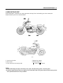
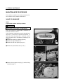
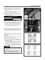
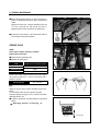
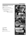
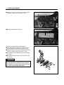
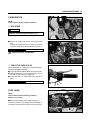
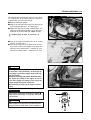
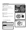
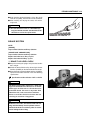
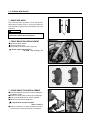
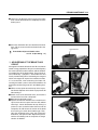
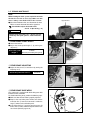
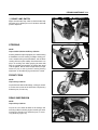
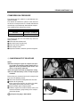
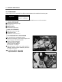
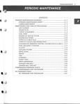
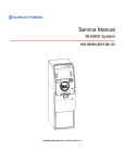
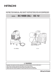
PERIODIC MAINTENANCE
CONTENTS
PERIODIC MAINTENANCE SCHEDULE
2- 1
PERIODIC MAINTENANCE CHART
2- 1
LUBRICATION POINTS
2- 2
MAINTENANCE PROCEDURES
2- 3
VALVE CLEARANCE
2- 3
SPARK PLUG
2- 5
EXHAUST PIPE NUTS AND MUFFLER MOUNTING BOLTS
2- 6
AIR CLEANER
2- 6
CARBURETOR
2- 8
FUEL HOSE
2- 8
CLUTCH
2- 9
ENGINE OIL
2- 9
ENGINE OIL FILTER
2-11
DRIVE CHAIN
2-12
BRAKE SYSTEM
2-14
STEERING
2-18
FRONT FORK
2-18
REAR SUSPENSION
2-18
TIRE
2-19
CHASSIS BOLTS AND NUTS
2-19
COMPRESSION PRESSURE
2-20
OIL PRESSURE
2-21
2
2-1 PERIODIC MAINTENANCE
PERIODIC MAINTENANCE SCHEDULE
The chart below lists the recommended intervals for all the required periodic service work necessary to keep the
motorcycle operating at peak performance and economy.
CAUTION
More frequent servicing should be performed on motorcycles that are used under severe conditions.
PERIODIC MAINTENANCE CHART
◉ ENGINE
Interval
Item
Air cleaner element
Initial 1,000 km
Every 4,000 km
Clean every 3,000 km
Every 8,000 km
Replace every 12,000 km
page
2- 6
Exhaust pipe nuts and
muffler mounting bolts
Tighten
Tighten
─
2- 6
Valve clearance adjust
Inspect
Inspect
─
2- 3
Spark plug
Clean
Clean
Replace
2- 5
Inspect
Inspect
─
Fuel hose
Replace every 4 years
2- 8
Engine oil filter
Replace
Replace
─
2-11
Engine oil
Replace
Replace
─
2- 9
Throttle cable
Inspect
Inspect
─
2- 8
Idle speed
Inspect
Inspect
─
2- 8
Clutch
Inspect
Inspect
─
2- 9
Initial 1,000 km
Every 4,000 km
Every 8,000 km
page
◉ CHASSIS
Interval
Item
Drive chain
Brake
Brake hose
2-12
Clean and lubricate every 1,000km
Inspect
Inspect
─
Inspect
Inspect
─
Replace every 4 years
Inspect
Brake fluid
Inspect
2-14
2-14
─
2-14
Replace every 2 years
Tires
Inspect
Inspect
─
2-19
Steering
Inspect
Inspect
─
2-18
Front forks
─
Inspect
─
2-18
Rear suspension
─
Inspect
─
2-18
Tighten
Tighten
─
2-19
Chassis bolts and nuts
CAUTION
Using poor quality replacement parts can cause your motorcycle to wear more quickly and shorten its useful life.
Use only genuine Hyoung replacement parts or their equivalent.
PERIODIC MAINTENANCE 2-2
LUBRICATION POINT
Proper lubrication is important for smooth operation and long life of each working part of the motorcycle.
Major lubrication points are indicated below.
① Clutch lever holder
② Drive chain
③ Side stand pivot and spring hook
④ Brake lever holder
⑤ Brake pedal pivot
O - Motor oil, G - Grease
NOTE:
� Before lubricating each part, clean off any rusty spots and wipe off any grease, oil, dirt or grime.
� Lubricate exposed parts which are subject to rust, with either motor oil or grease whenever the motorcycle has
been operated under wet or rainy condition.
2-3 PERIODIC MAINTENANCE
MAINTENANCE PROCEDURE
This section describes the service procedure for
each section of the periodic maintenance.
VALVE CLEARANCE
NOTE:
Inspect Initial 1,000 km and Every 4,000 km.
CAUTION
The clearance specification is for COLD state.
The valve clearance specification is different for
intake and exhause valves.
Valve clearance adjustment must be checked and
adjusted, 1) at the time of periodic inspection, 2)
when the valve mechanism is serviced, and 3)
when the camshaft is disturbed by removing it for
servicing.
● Remove the spark plug. (Refer to page 2-5)
● Remove the right air cleaner box.
● Remove the fuel tank. (Refer to page 4-1)
● Remove the cylinder head cover ① and ②.
②
①
[ Front Cylinder ]
[ Rear Cylinder ]
● Remove the magneto cover plug ③ and the timing
inspection plug ④.
④
③
PERIODIC MAINTENANCE 2-4
● Rotate the magneto rotor to set the front cylinder’s
piston at TDC (Top Dead Center) of the compression
stroke.
(Rotate the rotor until“|F”line on the rotor is aligned
with the center of hole on the crankcase.)
● To inspect the front cylinder’s valve clearance, insert
the thickness gauge to the clearance between the
camshaft and the tappet.
Valve clearance (when cold)
IN.
0.1 � 0.2 mm
EX.
0.2 � 0.3 mm
Thickness gauge : 09900-20806
● If the clearance is out of specification, first remove the
cam chain tensioner, camshaft housing, camshaft.
To install the tappet shim at original position, record
the shim NO. and clearance with“A”,“B”,“C”,“D”
mark on the cylinder head as the illustration.
Select the tappet that agree with tappet clearance
(vertical line) and shim NO.(horizontal line) as refer to the
tappet shim selection chart. (Refer to page 7-25∙26)
Adjust valve timing, install the camshaft housing and the
tensioner.
After the crankshaft rotate about 10 times, measure the
valve clearance.
If the clearance be not agree, adjust the standard clearance as the same manner above.
● In case that valve adjustment which there is no the
tappet shim selection chart, please follow instructions
of example in the below.
For example, the intake clearance is 0.4 and the shim
is 170 (1.70 mm), select 195 (1.95 mm) of the shim
which 170 (1.70 mm) of the shim add up the excess
clearance 0.25 mm when adjust with the standard
0.15 as the intake standard clearance 0.1�0.2 mm.
CAUTION
� Valve clearance should be checked when the
engine is cold.
� If you don t rotate the crankshaft about 10
times before measuring the valve clearance,
there is no meaning of valve clearance.
A
B
C
D
2-5 PERIODIC MAINTENANCE
● Rotate the magneto rotor to set the rear cylinder’s
piston at TDC(Top Dead Center) of the compression
stroke.
(Rotate the rotor 285�counter-clockwise from the
“|F”line, and until the“|R”line on the rotor is
aligned with the center of hole on the crankcase.)
● Inspect the rear cylinder’s valve clearance with the
same manner of the front cylinder.
SPARK PLUG
NOTE:
Clean Initial 1,000 km and Every 4,000 km,
Replace Every 8,000 km.
● Disconnect the spark plug caps.
● Remove the spark plugs.
TYPE
SPARK PLUG SPECIFICATION
Hot type
CR7E
Standard type
CR8E
Cold type
CR9E
Remove the carbon deposite with wire or pin and adjust
the spark plug gap to 0.7�0.8 mm, measuring with a
thickness gauge.
Spark plug gap
0.7�0.8 mm
Thickness gauge : 09900-20806
Check to see the worn or burnt condition of the electrodes.
If it is extremly worn or burnt, replace the plug.
And also replace the plug if it has a broken insulator,
damaged thread, etc.
● Install the spark plug, and then tighten it to specified
torque.
Spatk plug : 20~25 N∙m (2.0~2.5 kg∙m)
0.7~0.8 mm
PERIODIC MAINTENANCE 2-6
EXHAUSE PIPE NUTS AND MUFFLER
MOUNTING BOLTS
NOTE:
Tighten Initial 1,000 km and Every 4,000 km.
● Tighten the exhaust pipe nuts ①, and muffler mounting bolts ② to the specified torque.
Exhaust pipe nut
: 18~28 N∙m (1.8~2.8 kg∙m)
Muffler mounting bolt
: 20~30 N∙m (2.0~3.0 kg∙m)
①
[ Front Cylinder ]
①
[ Rear Cylinder ]
②
AIR CLEANER
NOTE:
Clean Every 3,000 km,
Replace Every 12,000 km.
● Remove the air cleaner case cover ③.
③
2-7 PERIODIC MAINTENANCE
● With the three of air cleaner cap mounting bolts
removed, remove the air cleaner cap ①.
①
● Remove the air cleaner element ②.
②
Clean the air cleaner element for the following:
● When the air cleaner element clean with the air gun,
necessarily blow at the inside by compressed air.
● Carefully examine the air cleaner element for tears during
cleaning. Replace it with a new one if it is torn.
● Assemble the element completely or damage severely
the engine.
● Be careful not to allow water to go inside the air cleaner element.
CAUTION
More frequent servicing may be performed on motorcycles that are used under severe conditions,
also clean the air cleaner element when replacing
the oil to prevent damage of the engine.
PERIODIC MAINTENANCE 2-8
CARBURETOR
NOTE:
Inspect Initial 1,000 km and Every 4,000 km.
◉ IDLE SPEED
CAUTION
Make this inspection when the engine is hot.
● Connect an engine tachometer to the high tension
cord.
Start up the engine and set its speed at anywhere
1,450 and 1,550 rpm by turning throttle stop screw ①.
Engine idle speed
①
1,450�1,550 rpm
Engine tachometer : 09900-26006
◉ THROTTLE CABLE PLAY
There should be 0.5�1.0 mm play on the throttle cable.
To adjust the throttle cable play.
● Tug on the throttle cable to check the amount of play.
● Loosen the lock nut ② and turn the adjuster ③ in or
out until the specified play is obtained.
● Secure the lock nuts while holding the adjuster in
place.
Throttle cable play �
0.5�1.0 mm
� �
� ③
FUEL HOSE
NOTE:
Inspect Initial 1,000 km and Every 4,000 km,
Replace every 4 years.
● Remove the left frame cover. (Refer to page 6-3)
Inspect the fuel hoses for damage and fuel leakage. If
any defects are found, the fuel hoses must be replaced.
②
2-9 PERIODIC MAINTENANCE
CLUTCH
NOTE:
Inspect Initial 1,000 km and Every 4,000 km.
↑
Clutch cable play �
↑
Clutch play should be 4 mm as measured at the clutch lever
holder before the clutch begins to disengage. If the play in
the clutch is incorrect, adjust it in the following way :
● Loosen the lock nut ① and screw the adjuster ② on
the clutch lever holder all the way in.
● Loosen clutch cable adjuster lock nut ③.
● Turn the clutch cable adjuster ④ in or out to acquire
the specified play.
● Tighten lock nut while holding the adjuster in position.
● The clutch cable should be lubricated with a light
weight oil whenever it is adjusted.
②
①
4 mm
④
③
◉ GEARSHIFT LEVER HEIGHT ADJUSTMENT
● Loosen the lock nut ⑤.
● With the link rod ⑥ turned, adjust the gearshift lever
height.
⑤
⑥
ENGINE OIL
NOTE:
Replace Initial 1,000 km and Every 4,000 km.
Necessary amount of engine oil
Oil change
1,450 ㎖
Filter change
1,500 ㎖
Overhaul engine
1,800 ㎖
Engine oil type
SAE 10W40
API SF or SG
�
PERIODIC MAINTENANCE 2-10
Oil should be changed while the engine is warm. Oil filter replacement at the above intervals, should be
together with the engine oil change.
● Keep the motorcycle upright.
● Place an oil pan below the engine, and drain the oil
by removing the filter cap ① and drain plug ②.
● Tighten the drain plug ② to the specified torque, and
pour fresh oil through the oil filter. Use an API classification of SF or SG oil with SAE 10W40 viscosity.
①
Oil drain plug : 18~20 N∙m (1.8~2.0 kg∙m)
● Start up the engine and allow it to run for several
minutes at idling speed.
● Turn off the engine and wait about three minutes,
then check the oil level through the inspection window. If the level is below mark“F”, add oil to“F”level.
If the level is above mark“F”, drain oil to“F”level.
②
CAUTION
Never operate the motorcycle if the engine oil level
is below the Lower line mark(L) in the engine oil
level gauge. Never fill the engine oil above the Upper line mark(F) .
Engine oil level being most suitable about 1mm under
the Upper line mark(F) of the engine oil lens. In
case of the engine oil pouring in excessively, the
engine output being made insufficient.
Be careful not to pouring in the engine oil excessively.
F
L
CAUTION
Necessarily, confirm and clean the oil strainer ③
when replace the Engine oil (specially, when first
replacement).
CAUTION
More frequent servicing may be performed on motorcycles that are used under severe conditions.
③
2-11 PERIODIC MAINTENANCE
ENGINE OIL FILTER
NOTE:
Replace Initial 1,000 km and Every 4,000 km.
● Drain the engine oil as described in the engine oil
replacement procedure.
● Remove the oil filter cap ①.
● Remove the oil filter.
● Install the new O-ring ②.
②
①
● Install the new oil filter.
● Install the new O-ring ③ and spring ④ to the oil filter
cap.
● Install the oil filter cap.
③
④
NOTE:
Before installing the oil filter cap, apply engine oil
lightly to the new O-ring ③.
◉ OIL FILTER INSTALLATION
CAUTION
INSERTION
DIRECTION
�
LUSTER MATERIAL
When install the oil filter, necessarily, HYOSUNG
character and 16510H05240 part s NO. install toward the outside, otherwise can damage the engine.
WARNING
Engine oil and exhaust pipes can be hot enough to
burn you.
Wait until the oil drain plug and exhaust pipes are
cool enough to touch with bare hands before draining oil.
HYOSUNG
16510H05240
�
OUTSIDE
PERIODIC MAINTENANCE 2-12
● Add new engine oil and check the oil level as
described in the engine oil replacement procedure.
CAUTION
Use HYOSUNG MOTORCYCLE GENUINE OIL FILTER only, since the other make s genuine filters
and after-market parts may differ filtering performance and durability, which could cause engine
damage or oil leaks. Hyosung motors genuine oil
filter is also not usable for the motocycles.
F
L
DRIVE CHAIN
NOTE:
Clean and Lubricate Every 1,000 km.
Visually check the drive chain for the possible defects
listed below. (Support the motorcycle by the jack or
block, turn the rear wheel slowly by hand with the transmission shifted to Neutral.)
● Loose pins
● Excessive wear
● Damaged rollers
● Improper chain adjustment
● Dry or rusted links
● Kinked or binding links
If any defects are found, the drive chain must be
replaced.
NOTE:
When replacing the drive chain, replace the drive
chain and sprocket as a set.
● Loose the axle nut ①.
②
①
● Tense the drive chain fully by turning both chain
adjusters ②, ③.
③
2-13 PERIODIC MAINTENANCE
● Count out 21 pins (20 pitches) on the chain and measure the distance between the two points. If the distance exceeds the service limit, the chain must be
replaced.
Drive chain 20-pitch length
Service limit
319.4 mm
● Loosen or tighten both chain adjusters ①, ② until the
chain has 20 � 30 mm of slack in the middle
between the engine and rear sprockets. The marks
③, ④ on both chain adjusters must be at the same
position on the scale to ensure that the front and rear
wheels are correctly aligned.
Drive chain slack
③
①
20 � 30 mm
● Place the motorcycle on jack or block for accurate
adjustment.
● After adjusting the drive chain, tighten the axle nut
to the specified torque.
● Tighten both chain adjusters ①, ② securely.
②
④
Rear axle nut : 90~140 N∙m (9.0~14.0 kg∙m)
● Recheck the drive chain slack after tightening the
axle nut.
20~30mm
PERIODIC MAINTENANCE 2-14
● Wash the drive chain with kerosine. If the drive chain
tends to rust quickly, the intervals must be shortened.
● After washing and drying the chain, oil it with a
engine oil.
CAUTION
� The standard drive chain is a RK-520DS Hyosung recommends that this standard drive chain
should be used for the replacement.
BRAKE SYSTEM
NOTE:
[ BRAKE ]
Inspect Initial 1,000 km and Every 4,000 km.
[ BRAKE HOSE & BRAKE FLUID ]
Inspect Initial 1,000 km and Every 4,000 km.
Replace the brake hoses Every 4 years,
Replace the brake fluid Every 2 years.
◉ BRAKE FLUID LEVEL CHECK
● Keep the motorcycle upright and place the handlebars straight.
● Check the brake fluid level by observing the lower
limit line (LOWER) on the front brake fluid reservoir.
● When the level is below the lower limit line (LOWER),
replenish with brake fluid that meets the following
specification.
Specification and Classification : DOT 3 or DOT 4
CAUTION
The brake system of this motorcycle is filled with
a glycol-based brake fluid. Do not use or mix different types of fluid such as silicone-based or
petroleum-based. Do not use any brake fluid
taken from old, used or unsealed containers.
Never re-use brake fluid left over from the last
servicing or stored for a long period.
CAUTION
Brake fluid, if it leaks, will interfere with safe running and immediately discolor painted surfaces.
Check the brake hoses and hose joints for cracks
and oil leakage before riding.
LOWER
2-15 PERIODIC MAINTENANCE
◉ BRAKE PAD WEAR
The extend of brake pad wear can be checked by
observing the grooved limit � on the pad. When the
wear exceeds the grooved limit, replace the pads with
new ones.
CAUTION
Replace the brake pad as a set, otherwise braking
performance will be adversely affected.
�
◉ FRONT BRAKE PAD REPLACEMENT
● Remove the brake caliper.
● Remove tne brake pads.
● To reassmble, reverse the above sequence.
Brake caliper mounting bolt
: 18~28 N∙m (1.8~2.8 kg∙m)
◉ FRONT BRAKE FLUID REPLACEMENT
● Place the motorcycle on a level surface and keep the
handlebars straight.
● Remove the master cylinder reservoir cap and diaphragm.
● Suck up the old brake fluid as much as possible.
● Fill the reservoir with new brake fluid.
Specification and Classification
: DOT 3 or DOT 4
● Connect a clear hose ① to the air bleeder valve and
insert the other end of the hose into a receptacle.
①
PERIODIC MAINTENANCE 2-16
● Loosen the air bleeder valve and pump the brake
lever until the old brake fluid is completely out of the
brake system.
● Close the air bleeder valve and disconnect the clear
hose. Fill the reservoir with new brake fluid to the
upper line.
Front brake caliper air bleeder valve
:6~9 N∙m (0.6~0.9 kg∙m)
◉ AIR BLEEDING OF THE BRAKE FLUID
CIRCUIT
Air trapped in the brake fluid circuit acts like a cushion to
absorb a large proportion of the pressure developed by
the master cylinder and thus interferes with the full braking performance of the brake caliper. The presence of
air is indicated by“sponginess”of the brake lever and
also by lack of braking force. Considering the danger to
which such trapped air exposes the machine and rider,
it is essential that, after remounting the brake and
restoring the brake system to the normal condition, the
brake fluid circuit be purged of air in the following manner :
● Fill the master cylider reservoir to top of the inspection window. Replace the reservoir cap to prevent dirt
from entering it.
● Attach a hose to the air bleeder valve, and insert the
free end of the hose into a receptacle.
● Bleed air from the brake system.
● Squeeze and release the brake lever several times in
rapid succession and sqeeze the lever fully without
releasing it. Loosen the bleeder valve by turning it a
quarter of a turn so that the brake fluid runs into the
receptacle, this will remove the tension of the brake
lever causing it to touch the handlebar grip. Then,
close the air bleeder valve, pump and squeeze the
brake lever, and open the valve. Repeat this process
until the fluid flowing into the receptacle no longer
contains air bubbles.
Upper limit line
2-17 PERIODIC MAINTENANCE
NOTE:
While bleeding the brake system, replenish the brake
fluid in the reservoir as necessary. Make sure that
there is always some fluid visible in the reservoir.
Upper limit line
● Close the air bleeder valve, and disconnect the hose.
Fill the reservoir with brake fluid to the upper line.
Front brake caliper air bleeder valve
: 6~9 N∙m (0.6~0.9 kg∙m)
CAUTION
Handle brake fluid with care : the fluid reacts
chemically with paint, plastics, rubber materials,
etc.
◉ REAR BRAKE PEDAL HEIGHT
● Loosen the lock nut.
● Adjust the brake pedal height � by turning the
adjuster ①.
Rear brake pedal
310 mm
height �
(When one person ridding at the ground)
①
�
◉ REAR BRAKE ADJUSTING
● Adjust the free travel � to 20~30 mm by turning the
adjusting nut ②.
Rear brake pedal free travel �
20~30 mm
�
②
◉ REAR BRAKE SHOE WEAR
This motorcycle is equipped with brake lining wear limit
indicator on the rear brake.
To check brake lining wear, perform the following steps.
● Make sure that the rear brake is properly adjusted.
● Depress the rear brake pedal. Make sure that the
extension line ③ from the index mark is within the
range ④ embossed on the brake panel.
● If the extension line ③ goes beyond the range, the
brake shoe assembly should be replaced with a new
set of shoes.(Refer to page 6-39)
④
③
PERIODIC MAINTENANCE 2-18
◉ BRAKE LAMP SWITCH
Adjust the rear brake lamp switch so that the brake lamp
will come on just before pressure is felt when the brake
pedal is depressed.
STEERING
NOTE :
Inspect Initial 1,000 km and Every 4,000 km.
Steering should be adjusted properly for smooth turning
of handlebars and safe running. Overtight steering prevents smooth turning of the handlebars and too loose
steering will cause poor stability. Check that there is no
play in th steering stem while grasping the lower fork
tubes by supporting the machine so that the front wheel
is off the ground, with the wheel straight ahead, and pull
forward. If play is found, perform steering bearing
adjustment as described in page 6-30 of this manual.
FRONT FORK
NOTE :
Inspect Every 4,000 km.
Inspect the front forks for oil leakage, scoring or scratches on the outer surface of the inner tubes. Replace any
defective parts, if necessary.
REAR SUSPENSION
NOTE :
Inspect Every 4,000 km.
Inspect the rear shock absorber for oil leakage and
mounting rubbers including engine mounting for wear
and damage. Replace any defective parts, if necessary.(Refer to page 6-43)
2-19 PERIODIC MAINTENANCE
TIRE
NOTE :
Inspect Initial 1,000 km and Every 4,000 km.
◉ TIRE TREAD CONDITION
Operating the motorcycle with excessively worn tires will
decrease riding stability and can lead to loss of control.
● Inspect stortage of tire thread s depth by the� tire wear
indicator �.
● Replace the front and rear tires at once when appear
the� tire wear indicator �.
◉ TIRE PRESSURE
If the tire pressure is too high or too low, steering will be
adversely affected and tire wear increased. Therefore,
maintain the correct tire pressure for good roadability or
shorter tire life will result. Cold inflation tire pressure is
as follows.
COLD INFLATION SOLD RIDING DUAL RIDING
TIRE PRESSURE KPa kgf/cm2 psi KPa kgf/cm2 psi
Front
172 1.75 25
172 1.75 25
Rear
196 2.00 29
221 2.25 32
CAUTION
The standard tire on
is 110/90-16 59S
for front and 150/80-15M/C 70S for rear.
The use of tires other than those specified may
cause instability. It is highly recommended to use a
HYOSUNG Genuine Tire.
CHASSIS BOLTS AND NUTS
NOTE :
Tighten Initial 1,000 km and Every 4,000 km.
Check that all chassis bolts and nuts are tightened to
their specified torque.(Refer to page 7-12)
Tire wear indicator
Tire wear indicator mark
PERIODIC MAINTENANCE 2-20
COMPRESSION PRESSURE
The compression of a cylinder is a good indicator of its
internal condition.
The decision to overhaul the cylinder is often based on
the results of a compression test. Periodic maintenance
records kept at your dealership should include compression reading for each maintenance service.
Compression pressure
Standard
14~16 kg/cm2 (at 600 rpm)
Service limit
12 kg/cm2 (at 600 rpm)
Low compression pressure can indicate any of the following conditions :
● Excessively worn cylinder wall
● Worn-down piston or piston rings
● Piston rings stuck in grooves
● Poor seating of valves
● Ruptured or otherwise defective cylinder head gasket
◉ COMPRESSION TEST PROCEDURE
NOTE:
� Before testing the engine for compression pressure, make sure that the cylinder head bolts are
tightened to the specified torque values and
valves are properly adjusted.
� Have the engine warmed up by idling before testing.
� Be sure that the battery used is in fully-charged
condition.
Remove the parts concerned and test the compression
pressure in the following manner.
● Loosen the oil cooler mounting bolts from the frame.
● Remove all the spark plug.
● Fit the compression gauge in one of the plug holes,
while taking care that the connection is tight.
● Keep the throttle grip in full-open position.
● Crank the engine a few seconds with the starter, and
record the maximum gauge reading as the compression of that cylinder.
Compression gauge : 09915-64510
2-21 PERIODIC MAINTENANCE
OIL PRESSURE
Check the oil pressure periodically. This will give a good indication of the condition of the moving parts.
Standard
Oil pressure
1.3 ± 0.2 ㎏/㎠
(at 60 ℃∙4,000 rpm)
If the oil pressure is lower or higher than the specification, the following causes may be considered.
◉ LOW OIL PRESSURE
● Oil leakage from the oil passage
● Damaged O-ring
● Defective oil pump
● Combination of above items
◉ HIGH OIL PRESSURE
● Engine oil viscosity is too high
● Clogged oil passage
● Combination of the above items
◉ OIL PRESSURE TEST PROCEDURE
Check the oil pressure in the following manner.
● Remove the oil check plug and install the adapter of oil
pressure gauge at the removed position.
● Connect an engine tachometer.
● Warm up the engine as follows :
Summer 10 min. at 2,000 rpm.
Winter 20 min. at 2,000 rpm.
● After warming up, increase the engine speed to
4,000 rpm. (with the engine tachometer), and read
the oil pressure gauge.
Oil pressure gauge : 09915-74510
Engine tachometer : 09900-26006