1
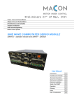
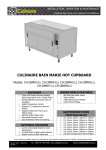
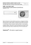
ELECTRIC CHAIN HOISTS
MH-5 / MHT-5 / MHC-5
SERVICE MANUAL
No.1
Contents
1.Precautions
1
2.Inspection & Replacement/Adjustment
1
2−1.Load chains
1
2−2.Hooks
1
2−3.Electromagnetic brake
2
2−4.Lubricant oil
4
3.Disassembly
5
3−1.Disassembly procedures
5
3−2.Electromagnetic brake - Inspections during disassembly
8
4.Assembly
4−1.Frame section
9
9
4−2.Gear section
11
4−3.Motor section (incl. Electromagnetic brake)
15
4−4.Limit switch section
17
4−5.Electrical parts & Wiring
18
4−6.Top hook assembly
20
4−7.Load chain, Bottom hook assembly, Stop holder
& Chain bucket assembly
4−8.Lubricant oil pouring
5.Spare parts list
21
22
23
1 . Precautions
・ Always cut off the power supply whenever the electric chain hoist is attempted for m
aintenanc or repair. Be sure to conduct maintenance or repair without load.
・ Always remove dirt from gears, load sheave, load chain and other related parts
after disassembly.
・ Never attempt to clean nor fix the bearings.
Replace if it is damaged.
・ Never reuse deformed, worn or corroded parts.
Always replace them with new ones.
・ Never use other than NITCHI genuine parts.
2 . Inspections & Replacement/Adjustment
2 − 1 . Load chains
Measure dimensions φ d (link diameter) and P (link pitch) as shown in Table 1.
The load chain must be replaced if it falls into any of the following state.
1 . Dimension "d" falls below the limit dimension given in Table 1.
2 . Dimension "P" exceeds the limit dimension given in Table 1.
Also, replace entire load chain if any link is damaged, deformed or rusty.
Table 1
Dimensions, Load chain
φd
Rated load
(t)
(㎜ )
P
Std.
Limit
Std.
Limit
Discard limit
pitch
per 10 links
Type
0.5∼ 1
φ 7.1
7.1
6.7
21.2
21.8
216
2∼ 5
φ 11.2
11.2
10.6
34.3
35.3
350
(Remark): In case wear is found on the load chain, please also check (p/B4) Load sheave
and (p/B6) Load chain guide as they are the counterparts each other.
Fig. 1
How to measure pitch dimension per 10 links with a caliper.
2 − 2 . Hooks
Measure dimension"A"for hook opening and dimension"H"for the thickness as per Table 2.
Replace the hook if it falls into any of the following conditions.
1 . Dimension"A"exceeds the standard dimension given in Table 2.
2 . Dimension"H"falls below the limit dimension given in Table 2.
Also, replace with new one if a crack is found on the part.
3 . The hook does not swivel on the level smoothly.
-1-
Table 2
Dimensions, Hook
( ㎜)
Top hook
Bottom hook
Rated load
A
H
A
H
(t)
Std.
Std.
Limit
Std.
Std.
Limit
0.5
1
32
31
29.5
23
28
23
27
21.9
25.7
2
33
35
33.3
33
35
33.3
2.5, 3
41
42
39.9
41
42
39.9
5
48
55
52.3
48
55
52.3
2 − 3 .Electromagnetic brake
・ Electromagnetic brake for 3-Phase models (MH-5 & MHT-5)
Measure the dimension of the brake clearance between (p/C59-4) Armature and (p/C59-5)
Brake coil (Dimension A as per Fig 2 below) with a thickness gauge. The brake needs
adjustment according to the procedures through 1-4 as given below if the measured
value is 0.8mm or over.
③
①
②
Fig.2
Electromagnetic brake for 3-Phase models
1 . Loosen Fixing screws for Detent plate and remove (p/C59-6) Detent plate.
2 . Screw up Hex. nylon nut to adjust the clearance (Dimension A) to be between
0.3mm and 0.5mm while checking with a thickness gauge. (The arrowed points ① ,②,③
show the measuring positions for equal setting.)
3 . Attach (p/C59-6) Detent plate after the adjustment. Turn the hex. nylon nuts so
that either their corners or sides touch the side of Detent plate.
(The corners of the nuts are in touch with Detent plate in the above figure.)
4 . Fix Detent plate with Fixing screws.
-2-
・ Electromagnetic brake for 1-Phase model (MHC-5)
Measure the dimension of the brake clearance between (p/C59-4) Armature and (p/C59-5)
Brake coil (Dimension A as per Fig 3. below) with a thickness gauge. The brake needs
adjustment according to the procedures through 1-8 as given below if the measured
value is 0.8mm or over at the condition the brake is being mounted on the hoist
(or, 1.8mm or over if the brake is set loose.)
③
①
Fig.3
Electromagnetic brake for 1-Phase model
②
1 . Loosen Fixing screws for Detent plate and remove (p/C59-6) Detent plate.
2 . Screw up Hex. nylon nut to adjust the clearance (Dimension A) to be between
1.3mm and 1.5mm while checking with a thickness gauge. (The arrowed points ① ,②,③
show the measuring positions for equal setting.)
3 . Attach (p/C59-6) Detent plate after the adjustment. Turn the hex. nylon nuts so
that either their corners or sides touch the side of Detent plate.
(The corners of the nuts are in touch with Detent plate in the above figure.)
4 . Fix Detent plate with Fixing screws.
5 . Lace brake lead-wires through (p/C49) Pipe for lead wire, and outfit the hoist
with the brake assembly using M6 Cap bolts.
6 . Screw up (p/C20) Adjusting nut for brake to the bottom, then turn it reversely
for one complete turn (for 1mm pitch).
7 . Fasten (p/C555) Cap bolts. If the holes of (p/C20) Adjusting nut for brake and
the tap holes of (p/C4) Brake wheel do not align each other, match the holes by
turning C20 clockwise or counterclockwise within the turning range of max. 45° .
8 . Screw up (p/C719) Bearing U nut to complete the brake installation.
Fig.4
Electromagnetic brake installation for 1-Phase model
-3-
2 − 4 .Lubricant oil
1 . The hoist is filled with lubricant oil
at initial delivery, hence it is not
necessary to add oil for the first run.
Make a small hole on (p/A505) Oil cap
as illustrated on the right, so that
the internal pressure of (p/A1) Gear
box does not increase during operation.
2 . Check the oil level at periodic inspection.
Add oil in (p/A1) Gear box according to
Fig. 5 Lubricant oil
Table 3 below if it is at the lower level.
Runout or short of oil causes abnormal noise
in the gear box and/or malfunction of the
mechanical brake. Table 3 provides recommended
oil type and quantity per model/capacity to
replace or replenish the oil.
Table 3 Oil type & quantity
3 . Lubrication on Load chain
MH-5・MHT-5
MH-5
MHT-5
Make sure the load chain is
MHC-5 0.5∼ 1t
2∼ 5t
2∼ 5t
always lubricated.
Diesel oil
Diesel oil
SHELL
Any machine oil or gear oil
CD #30(API)
CD #30(API)
Tonna oil
is recommendable.
0.8 liters
1.5 liters
1.5 liters
-4-
3 . Disassembly
3 − 1 . Disassembly procedures
②
②
③
①
1. Unjoint (p/B32) Chain bucket pin
2. Take off (p/C12) Switch cover and disconnect the wirings of ① (p/C563)
and the hanging chain and remove
Power source cable, ② (p/C564) Pendant control cable and ③ (p/C635)
(p/B27) Chain bucket.
Limit cable.
Bundle each group of wires at this stage.
It helps to
ease your job.
④
⑤
3. Open (p/B30-2) Body cover B, and
4. Strip the electrical components.
disconnect the lead-wires*.
(Plug) located in the bottom of
(p/A1) Gear box and drain the oil.
*④ : Wires from Switch holder section
To open (p/A505) Oil cap will make
⑤ : Black wires … Wires from the motor.
it faster.
Blue wires … Wires from the brake.
6. Pull out (p/B18) Top hook pin
5. Unscrew (p/A537) Oil extractor
7. Loosen
(p/A559) Cap bolts w/
and dismantle (p/D1) Top hook
seal and take off (p/A29) Switch
assembly from the frame section.
holder.
8. Remove (p/A560) Gasket for A29.
Always replace (p/A559)
Cap bolts with seal with the new
ones.
9. Disassemble (p/C27) Limit switch
cover.
10.Disconnect (p/C32) Limit switch
plate.
-5-
11.Take off (p/C1) Motor cover.
12.Dismantle (p/C59) Brake unit.
13.Loosen (p/C664) Through bolts
and remove (p/C45) Shield.
15.Pull out (p/A2) Pinion shaft
16.Remove (p/A1) Gear box.
(w/ Rotor).
14.Take off (p/C49) Pipe for lead
wire and (p/C3) Stator for motor.
17.Disengage whole the mechanical
brake set and the third pinion
set.
Be careful of losing the
needles of (p/A508) Needle
bearing for 2-5t capacities.
18.Unfasten (p/A556) Nut and
19.Pick up (p/B1-4) Stay pipe A.
detach (p/A28) Brake supporting
20.Remove (p/A510) Retaining ring
and disengage (p/A7) Load gear.
plate.
21.Pull out (p/B5) Collar for B4
Load sheave.
22.Detach (p/B25) Chain limit stop, 23. Remove (p/B26) Load chain.
(p/D8) Bottom hook assembly and
(p/B536) Tail springs from
the load chain.
-6-
24. Unfasten (p/B538) Nut and
(p/C525) Cap bolt, to separate
25. Release (p/B566) Retaining ring
and remove (p/B36) Limit lever.
26. Take off (p/B28) Hanging plate
for (p/B27) chain bucket,
(p/C44) Motor flange and (p/B35)
(p/B537) Springs for B6 then
Stay pipe B <0.5&1t> or (p/B1-3)
(p/B10) Handle.
Stay bolt B <2-5t> from (p/B29)
Motor-side plate and detach
(p/B1) Gear-side plate.
27. Dismantle (p/B6) Load chain
guide.
28. Detach (p/B503) Oil seal for B4,
(p/B28) Hanging plate for B27
then (p/B4) Load sheave.
-7-
3 − 2 . Electromagnetic brake unit-Inspections during disassembly
Fig.6-a,6-b shows disassembled (p/C59) Electromagnetic brake unit and the list of its
components.
Measure (p/C4) Brake wheel thickness "t" and replace with new one if it falls to or
below the limit dimension as given in Table 4 below.
④
⑤
③
②
⑨
①
⑦
⑧
⑩
① Brake base plate
② Brake wheel
③ Armature
④ Brake coil
⑤ Detent plate
⑥ Hex. nylon nut
⑦ Brake stay bolt
⑧ Fixing screw for Detent
⑨ Brake auxiliary spring
⑩ Brake spring
⑥
Fig. 6-a MH-5 & MHT-5
④
⑤
③
①
②
⑨
⑦
⑧
⑩
⑥
Fig. 6-b MHC-5
Table 4
Brake wheel dimension t (mm)
MHC-5
6
5
MH-5 MHT-5
Std.
Limit
7
6
Remark: Never attempt to disassemble ① Brake base plate, ⑦Brake stay bolt
and its hex. nut apart. They are connected with locking agent.
-8-
C59-1
C 4
C59-4
C59-5
C59-6
plate
C59-8
C59-7
4 . Assembly
4 − 1 . Frame section
Please replace the parts with new ones if they fall into the following conditions.
1 . Gear-/Motor-side plates
: Bearings (p/B507,508) rattle on the holes, or wear or
(p/B1,B29)
deformation on the hole for (p/B18) Top hook pin is
found.
2 . Load sheave (p/B4)
: Either wear, deformation or flaws are found at any of
shank, spline or chain pocket section. Or, whenever
(p/B26) Load chain is to be replaced.
3 . Oil seals (p/B502,B503)
: Wear or flaws are found whereat they touch with (p/B4)
Load sheave or (p/A2) Pinion shaft (w/ Rotor).
4 . Load chain guide (p/B6)
: Wear or deformation is found on its internal groove.
Or, whenever (p/B26) Load chain is to be replaced.
5 . Handle (p/B10)
: Deformation or wear is found on its movable section
or on the crossed slit.
Assembly procedures
1. Set (p/B4) Load sheave with
2. Fit one of two (p/B28) Hanging
3. Build in (p/B6) Load chain guide.
(p/B503) Oil seal to (p/B1) Gear-
plates for B27 on the stay bolt
Be careful of its position in
side plate, then fit (p/B501)
located on (p/B1) Gear-side plate
relation to the stay bolt.
Rubber seal in the position as
as the above photo.
(See white circle above.)
the sketch given below.
B501 Rubber seal
B4 Load sheave
-9-
B567 Support spring
for 2∼5t capacity
4. Grease to the stay bolt beneath
5. Put 2 pcs. (p/B537) Springs for
(p/B6) Load chain guide and
B6 in the position as above.
6. Put also (p/B567) Supporting
spring with (p/B568) Cap bolt in
furnish (p/B10) Handle over it.
7. Put the rest of (p/B28)
case of a 2∼ 5t capacity unit.
8. Fix (p/B29-2) Body cover A on
9. Join (p/B1) Gear-side plate and
Hanging plates for B27 to the
(p/B29) Motor-side plate with
(p/B29) Motor-side plate, then
stay bolt.
(p/B572) Cap bolt.
retain (p/B36) Limit lever with
Then grease to the
fork plate of (p/B10) Handle and
(p/B566) Retaining ring.
set (p/B36) Limit lever over it.
of a 2∼5t capacity unit, put
In case
(p/B1-3) Stay bolt B into the
position of (p/B35) Stay pipe B
in the step 10 as given below.
10. Set (p/B35) Stay pipe B between
the plates and insert (p/B574)
11. Tighten up (p/B538) Nuts.
(4 points)
※1
Insert pilot chain from the
loose-end side.
Be sure the first
Bolt through the pipe in case of
link to be inserted is a
a 0.5-1t capacity unit.
※2
horizontal link for the single
chain-fall unit while the first
link is a vertical link in case of
a double chain-fall unit.
Feed the chain to the load-side
turning (p/B4) Load sheave by the
fingers.
※1 Pilot chain ・ ・・ A short preliminary link chains to be set through the load sheave in advance, in order to
guide the practical load chain at chaining.
Prepare odd numbers of the links.
※2 Horizontal link ・ ・・The load chain links which lie in the load sheave pockets in horizontal aspect.
※3 Vertical link ・・ ・・The load chain links which set to the load sheave pockets in perpendicular aspect.
- 10 -
4 − 2 . Gear section
Replace the parts with new ones if they fall into the following conditions.
1 . Any wear or flaw is found on the gear teeth.
2 . Rattling or any damage is found the bearings (p/A507,A508,A509,A553,A554,B507).
Assembly procedures
1. Insert (p/B5) Collar for B4 to
the load sheave.
4. Fix (p/A28) Brake supporting
plate with 3 (p/A556) Nuts.
2. Set (p/A7) Load gear to (p/B4)
Load sheave and clamp it with
the Stay bolts, so that their
(p/A510) Retaining ring.
chamfered end faces (p/B1) Gear-
※1
side plate.
Be careful of its aspect.
5. Build the third pinion assembly
in the position.
Clamp the gear
with (p/A513) Retaining ring.
7. Furnish the third pinion and the
3. Put (p/B1-4) Stay pipes A over
8. For MH-5/MHT-5 0.5-1t and MHC-5,
mechanical brake assemblies with
clamp (p/A553) Ball bearing on
(p/A507,A553) Ball bearings
the mechanical brake with
respectively.
(p/A561) Ring for Bearing.
- 11 -
6.
※3
Equip the mechanical brake
assembly and catch a ratchet
tooth with (p/A16) Pawl properly.
9. Put (p/A501) O-Ring on (p/A1)
Gear box with bond.
10. Align (p/A1) Gear box with
(p/B1) Gear-side plate using
(p/A558) Spring pins, then fix
with (p/A519, A562) Cap bolts.
※2
A562 is to fix (p/B30-1,B30-2)
Body covers B and is different
from A519 in size.
※1 (p/A7) Load gear aspect:
0.5∼ 1t capacity ... The depressed side of the gear faces the (p/A28) Brake supporting plate.
2∼5t capacity ... Side of the thicker spline flange faces the (p/A28) Brake supporting plate.
※2 Size of (p/A562) Cap bolts to fix (p/B30-1,B30-2) Body covers B.
MH,MHT,MHC
0.5∼ 1t
MH 2∼ 3t
MHT 2∼ 2.5t
MH,MHT
5t
- 12 -
M6× 18 2pc.
M8× 18 2pc.
M8× 18 1pc.
※Mechanical brake assembly
①
②
③
④
⑤
⑥
⑦
1 .Follow procedures through ① to ⑦ as the above photos.
・ At procedure ⑦, screw up (p/A3) Pinion gear to the bottom first,
then insert (p/A15) Check washer.
Be careful of its arm's position.
The arm of Check washer hits the projection of the pinion gear when
it gets loose, and it stops the rotation.
・ Either face of (p/A15) Check washer can be used.
・ Oil (p/A514) Friction discs in advance for assembly.
・ Replace (p/A514) Friction discs with new ones when they wear at
thickness (t) over the limit dimension as given below.
(p/A514) Friction discs dimension
Thickness t (mm)
Std.
3
Limit
2.4
- 13 -
2 .Adjust the clearance between Check washer arm and the projection of
Pinion gear to 1mm or less by meshing (p/A15) Check washer on the
different threads of (p/A4) Second pinion gear and/or by turning over
Check washer to the other face.
- 14 -
4 − 3 . Motor section (incl. Electromagnetic brake)
Replace the parts with new ones if they fall into the following conditions.
1 . Any wear is found on the helical gear or the spline portion of (p/A2) Pinion
shaft (w/ Rotor).
2 . Rattling or any damage is found the bearings (p/B506,C669).
Assembly procedures
1. Set (p/B506) Ball bearing to
2. Insert (p/A2) Pinion shaft (w/
(p/B29) Motor-side plate.
Rotor) to (p/B29) Motor-side
while passing the motor lead wires
fit (p/C681) Bushing for motor
plate.
through (p/C681) Bushing for motor
lead wire and (p/C560) Blind
bottom.
Also,
Be sure to set it to the
3. Attach (p/C3) Stator for motor
lead wire on the plate. Be careful
bushing in each position.
not to pinch the wires between the
plate and the stator.
4. Align (p/C3) Stator for motor
5. Set (p/C49) Pipe for lead wire on 6. Lace the brake lead wires through
using (p/C664) Through bolt on
(p/B29) Motor-side plate. Furnish
(p/C49) Pipe for lead wire and fix
its location.
(p/C45) Shield with (p/C619) Wave
※
motor-lead wires and take off
washer [(p/C670) Rubber washer
section with Hex. socket cap
the bolt when alignment is done.
for MHC-5] and (p/C669) Ball
bolts.
Be careful of the
bearing, then mount it over
(p/C3) Stator for motor.
Align
(p/C45) Shield and fix it with
(p/C664) Through bolts.
- 15 -
(p/C59) Brake unit to the motor
7. Fix (p/C1) Motor cover with (p/C524)
Screws.
※Electromagnetic brake unit assembly
Please follow as illustrated below. Be sure to align both the center of (p/C4) Brake
wheel and (p/C59-1) Brake base plate in assembly.
Refer to Section 2-3. for the brake clearance inspection & adjustment.
- 16 -
4 − 4 . Limit switch section
Assembly procedures
Parallel
1. Set (p/C634) Limit switch at the
2. Fit (p/C32) Limit switch plate
3. Connect (p/C32) Limit switch plate
neutral position by turning the
with (p/C634) Limit switch so
to (p/B29) Motor-side plate with
key shaft so that its arrowed
that the labeled side of the
(p/C630) Cap bolts, and pass
side meets the arrow on the
switch faces up.
plate.
(p/C626) Screws to parallelize
(p/C560) Blind bushing to the
the upper side of the switch body
middle of the side plates.
Then fix with
(p/C635) Limit cables through
and the side of the key shaft as
the above photo.
4. Attach (p/C27) Limit switch
cover.
※ Test both the limits for up and down direction with (p/B10) Handle.
If only one side of the
limits operates, make adjustment by changing the angle of the limit switch body over
the slits on its fin plate with (p/C626) screws.
properly.
- 17 -
Make sure both sides of the limit functions
4 − 5 . Electrical parts & Wiring
Assembly procedures
1. Outfit (p/A2) Pinion shaft with
(p/A32) Bearing bush in case of
2. Outfit (p/A2) Pinion shaft with
(p/A509) Ball bearing.
3. Lay (p/A560) Gasket for A29 on
(p/A1) Gear box and coat with
MHT 0.5∼ 1t or MHC-5 before
water resistant adhesive around
procedure 2. in the right.
(p/A30) Pipe.
Gear side
4. Connect (p/A29) Switch holder
5. Pass (p/C635) Limit cables
Motor side
6. Run the lead wires of the
with (p/A559) Cap bolts w/ seal.
through (p/A30) Pipe to the side
electrical components through
(Always use new bolts because
of (p/A29) Switch holder.
the open space above (p/B6) Load
A559 is coated with sealant.)
Assemble the electrical unit on
chain guide to the side of
(p/C50) Switch board and install
(p/B30-2) Body cover B.
it to (A29) Switch holder with
Connect both of Body covers B,
(p/C687) Cap bolts.
i.e. B30-1 and B30-2 with (p/C682)
Lace the wires of the electrical
Terminal board, then connect the
components through (p/A30) Pipe
wires on the terminal.
to the middle of (p/B1,B29) Gear& Motor-side plates.
- 18 -
7. Put in (p/C694) Cord locks and
set (p/C563) Power source cable
8. Close (p/B30-1) Body cover B with 9. Close (p/B30-2) Body cover B while
(p/B542) Screws.
retaining (p/C563) Power source
and (p/C564) Pendant control
cable by (p/C34) Supporter for
cable into (p/A29) Switch holder.
C563 over (p/C662) Protection pipe
Follow the circuit diagram for
for C563.
the wiring.
A29 Switch holder
C42 Supporting plate for C23
B564 Pendant control cable
10. Fix (p/C42) Supporting plate for 11. Connect one of (p/C23) Hanging
C23 in its position.
12. Connect the power to confirm the
plates for C533 to (p/C42) Supporting
operation.
plate. Then hold (p/C564) Pendant
section with (p/C12) Switch cover
control cable with the other (p/C23)
over (p/C666) Gasket for C12 and
Hanging plate for C533, and fix them
tighten up (p/C667) Cap bolts if
so to hang them on (p/C42) Supporting
the assembled unit is perfect.
plate for C23.
(Have the trial within the stroke
While hang the end of
Close the switch
the pendant cable protection wire to
of the pilot chain and keep it
the bottom of C23.
being reeved through the load
sheave.)
- 19 -
4 − 6 .Top hook assembly
・ 0.5∼ 3t Capacities
B29 Motor-side plate
・ 5t Capacity
・ Be sure to grease to (p/B18) Top hook pin for assembly.
・ Split (p/B514) Split pins at 60 degree.
- 20 -
4 − 7 . Load chain, Bottom hook assembly, Stop holder & Chain bucket assembly
・ Load chain
Pilot chain
'C' link
B26 Load chain
1. Joint (p/B26) Load chain to the
2. Press 'DOWN' push button to feed
loose-end side of the pilot chain
(p/B26) Load chain into the unit
using a 'C' link (open link).
then unjoint the pilot chain.
※ Make sure the weld-abutment of the vertical links
face to the opposite side of the load sheave center.
・ Bottom hook assembly, Stop holder & Chain bucket assembly
3. Equip (p/B536) Tail springs to
4. Connect Chain bucket hanging chain
both the end of the load chain,
to (p/B28) Hanging plate for B27
then connect (p/D8) Bottom hook
and couple (p/B27) Chain bucket to
assembly with (p/D12) Bolt for D8
the unit inserting (p/B32) Chain
to the load side and (p/B25)
bucket pin in its position.
Chain limit stop to the loose-end
lock it with the split pins.
side.
The load chain must get into the
Then
the bucket from the end link in
smooth order.
・ Double chain-fall unit
1. Equip (p/B536) Tail spring to the load side of Load chain.
At the same time make sure the first link at the loaded end is
a vertical link.
2. Reeve Load chain through
※
(p/D8) Bottom hook assembly so that
the weld-abutment of vertical links face to (p/D6) Tail wheel
center.
3. Join Load chain end to (p/D2) Chain stop plate with (p/D12)
Bolt for D8 and nut.
4. Connect (p/D2) Chain stop plates to (p/D1) Top hook assembly
7th Link
with (p/D3) Yoke pin (w/ Nut).
5. Connect (p/B25) Chain limit stop on the 7th link from the end as
illustrated on the left.
- 21 -
※Bottom hook assembly
1 . Attach (p/83) Tail wheel collars to (p/D6) Tail wheel then assemble to the bottom
hook with (p/D8-11) Tail wheel guides B.
2 . Grease to (p/D9) Tail wheel pin and insert to the position.
3 . Fit (p/D8-10) Tail wheel guide A and fasten up with bolts.
(Slot it into the groove on (p/D9) Tail wheel pin as the photo given below.)
(p/D6) Tail wheel
(p/D8-11) Tail wheel guide B
(p/D8-10) Tail wheel guide A
(p/D9) Tail wheel pin
4 − 8 . Lubricant oil pouring
1. Coat to the thread section of (p/A537) Oil
extractors with gasket, and plug on 2 points
of (p/A1) Gear box.
2. Plug the oil hole with (p/A505) Oil cap and make sure
a depressurizing hole is being made on top of the cap.
Then pour the lubricant
oil after confirming all the bolts and nuts
are tightened up firmly.
- 22 -
5. MH-5 Spare Parts List
☆
☆
☆
☆
GEAR BOX
PINION SHAFT
PINION GEAR
SECOND PINION
SECOND PINION GEAR
THIRD PINION
LOAD GEAR
DISC HUB
( ) shows old style
RATCHET WHEEL
CHECK WASHER ( ) shows old style
PAWL
BRAKE SUPPORTING PLATE
SWITCH HOLDER
PIPE
O-RING
OIL CAP
BALL BEARING
ROLLER BEARING
NEEDLE BEARING
BALL BEARING
RETAINING RING
RETAINING RING
A514
FRICTION DISCS
1set
A519
A523
A530
A531
A537
A553
A554
A556
A557
A558
CAP BOLTS
SPRING WASHER
PAWL SPRING
RETAINING RING
OIL EXTRACTOR PLUG
BALL BEARING
BALL BEARING
NUTS
SPRING WASHER
SPRING PINS
8(9)
10
1
2
2
1
1
3
3
2
4
7
1
1
2(1)
A1
A2
A3
A4
A5
A6
A7
A13
A14
A15
A16
A28
A29
A30
A501
A505
A507
A508
A509
A510
A513
☆
Part Name
☆
A559
CAP BOLT W/SEAL
☆
A560
A561
A562
GASKET FOR A29
RING FOR BEARING
CAP BOLTS
Part
Number
☆
☆
☆
☆
B1
B1-3
B1-4
B4
B5
B6
B10
B18
Part Name
GEAR-SIDE PLATE
STAY BOLT B
STAY PIPE A
LOAD SHEAVE
COLLAR FOR B4
LOAD CHAIN GUIDE
HANDLE
TOP HOOK PIN
☆
B25
☆
★☆
B26
B27
B28
B29
B29-2
B30-1
B30-2
B32
B35
B36
B38
B501
B502
B503
B506
B507
B508
B509
B514
LOAD CHAIN
CHAIN BUCKET
HANGING PLATE FOR B27
MOTOR-SIDE PLATE
BODY COVER A
BODY COVER B
BODY COVER B
CHAIN BUCKET PIN
STAY PIPE B
LIMIT LEVER
CHAIN GAUGE
RUBBER SEAL
OIL SEAL
OIL SEAL FOR B4
BALL BEARING
BALL BEARING
NEEDLE BEARING
RETAINING RING
SPLIT PINS
B522
CAP BOLTS
☆
☆
☆
☆
☆
☆
☆
Recommended Parts marked ★ is for Light Duty use and ☆ is for Heavy Duty use.
Nos.
used
1
1
1
1
1
1
1
1
1
1
1
1
1
1
1
1
1
1
1
1
1
1
Part
Number
CHAIN LIMIT STOP
B523
LOCK NUTS
B533
B536
B537
RETAINING RING
TAIL SPRINGS
SPRINGS FOR B6
B538
NUTS
B539
SPRING WASHER
B540
B541
CAP BOLT
SPRING WASHER
B542
SCREWS
B545
B546
B550
B566
B567
B568
B569
B572
B573
B574
CAP BOLT
NUT
SPRIT PINS
RETAINING RING
SUPPORTING SPRING
CAP BOLT
SPRING WASHER
CAP BOLT
SPRING WASHER
BOLT
Nos.
used
1
1
3
1
1
1
1
1
1
2
1
1
1
1
1
1
1
1
1
1
1
1
1
1
1
1
1
1
2
2
4
2
4
1
2
2
4
5
4
5
1
1
4
2
1
1
2
1
1
1
1
1
1
1
Part Code
0.5t
1t
2t
3t
5t
GMH5A001U
LMH5A001U
LMH5A002U
GMH5A002U
JMH5A002U
LMH5A003
GMH5A003
GMH5A004
JMH5A004
LMH5A004
MMH5A004
PMH5A004
GMH5A005
JMH5A005
LMH5A005
MMH5A005
PMH5A005
MH4005A06
LMH5A006
MH4020A07
MH4005A07
(MH4020A13)/LMH5A013
(MH4005A13)/GMH5A013
MH4005A14
MH4020A14
(MH4005A15)/GMH5A015
GMH5A016
MH4020A16
LMH5A028T
MH4005A28T
GMH5A029
LMH5A029
MH4005A30
LMH5A030
MH4020A501
MH4005A501
MH4005A505
B6202ZNR
B6303ZNR
T153511
T204725ZNR
B6303NRZ
SRC5140
SRC5145
SRC5124
SRC5130
MH4005A514
MH4020A514
MH4005A515
MH4020A515
CBM6×10
CBM8×10
SWM6
SWM8
MH4005A530
MH4020A530
SRC5116
SRC5118
TPO.25
B6202ZNR
B6302ZNR
B6202ZNR
B6303ZNR
HN1M8
HN1M10
SWM8
SWM10
SPP6×10
MH4005A559
MH4005A559
GMH5A560
LMH5A560
GMH5A561
CBM6×18
CBM8×18
0.5t
1t
GMH5B001S
MH4005B014
GMH5B004
MH4005B05
GMH5B006
GMH5B010
MH4005B18
MH4005B25
CT-7.1
MH4005B28
GMH5B029U
GMH5B0292T
GMH5B030T1
GMH5B030U
MH4005B32
MH4005B35
MH4005B36T
GMH5B037U1
SC426512
B6208Z
SRC5080
SP5×30
MH4005B53E
MH4005B53F
HN1M12
SWM12
CBM6×15
SWM6
CBM8×10
HBBM12×100
Parts Code
2t
3t
LMH5B001S
MH4020B013
MH4020B014
LMH5B004
MH4020B05
LMH5B006
LMH5B010
MH4020B18
MH4020B25
CT-11.2
NO.1-NO.5 & S1-S7
MH4020B28
LMH5B029U
LMH5B0292T
LMH5B030T2
LMH5B030U
MH4020B32
MH4020B36T
LMH5B037U2
MH4005B501
SC487012
SC25408
B6305ZZC3D4M
B6209Z
TA5025
SRC5085
SP5×40
CBM6×30
HNN1M6
SRC5062
MH4020B53E
MH4020B53F
HN1M14
SWM14
CBM8×18
SWM8
CMSM6×15
CBM6×20
HNN1M6
SP3×20
SRC5122
MH4020B567
CBM12×35
SWM12
CBM8×12
SWM8
-
- 23 -
Remarks
Old style is Discontinued
Old style is Discontinued
Old style is Discontinued
( ) is applied to 5t
( ) is applied to 5t
Remarks
5t
MH4020B25
Refer to the Operating Handbook
CBM6×30
HNN1M6
Old style
Old style
CMSM6×15
Part
Number
Part Name
C1
MOTOR COVER
C3
STATOR FOR MOTOR
☆
★☆
☆
★☆
☆
★☆
★☆
★☆
☆
☆
★☆
Nos.
used
1
1
C4
C12
C23
C27
C32
C34
C42
C44
C45
C46
C47
C48
C49
C50
C51
C52
C59
C59-5
C512
C514
C524
C525
C533
C553
C560
C563
C564
C565
C584
C585
C603
C604
C605
C607
C609
C610
C614
C615
C619
C626
C628
C629
C630
C634
C635
C638
C639
C640
C642
C652
C653
C654
C655
C657
C659
C662
C664
C665
C666
C667
C668
C669
C671
C673
C674
C675
C676
C677
C678
C679
C680
C681
C682
C683
C684
C687
C688
C691
C692
C693
C694
C700
C701
C702
72
BRAKE WHEEL
SWITCH COVER
HANGING PLATE FOR C533
LIMIT SWITCH COVER
LIMIT SWITCH PLATE
SUPPORTER FOR C563
SUPPORTING PLATE FOR C23
MOTOR FLANGE
SHIELD
BRAKE BASE PLATE
ARMATURE
BRAKE COIL
PIPE FOR LEAD WIRE
SWITCH BOARD
CONNECTING PLATE FOR C563
CONNECTING PLATE FOR CABLE
BRAKE UNIT
BRAKE COIL
PUSH BUTTON
NAME PLATE
SCREWS
CAP BOLT
SUPPORTING CHAIN FOR C564
BRAKE SPRING
BLIND BUSHING
POWER SOURCE CABLE
PENDANT CONTROL CABLE
RING
CAP BOLTS
SPRING WASHER
SCREWS
SCREWS
SCREWS
ELECTROMAGNETIC CONTACTOR
TRANSFORMER
WARNING RELAY OF NEGATIVE PHASE
SPRING WASHER
SPRING PINS
WAVE WASHER
SCREWS
CAP BOLTS
SPRING WASHERS
CAP BOLTS
LIMIT SWITCH
LIMIT CABLE
SCREWS
NUT
SPRING WASHER
SCREWS
NUT
CAP BOLT
SPRING WASHER
SCREWS
SPRING WASHERS
GASKET FOR MOTOR CASE
PROTECTION PIPE FOR C563
THROUGH BOLTS
SPRING WASHERS
GASKET FOR C12
CAP BOLTS
SPRING WASHERS
BALL BEARING
CAP BOLTS
ADJUSTING NUTS FOR BRAKE
CAP BOLTS
SPRING WASHERS
BUSHING FOR LEAD WIRE
RECTIFIER
SCREWS
TERMINAL BOARD
SCREWS
BUSHING FOR MOTOR LEAD WIRE
TERMINAL BOARD
SCREWS
SCREWS
CAP BOLT
SPRING WASHERS
GASKET FOR C51
GASKET FOR C52
SCREWS
CORD LOCKS
TERMINAL BOARD
SCREWS
TERMINAL BOARD
SAFETY LINK
1
1
2
1
1
1
1
1
1
1
1
1
1
1
1
1
1
1
1
1
3
1
1
3
1
1
1
3
1
1
4
4
( )
1
1
1
1
2
1
2
2
2
2
1
1
1
1
1
1
1
1
1
2
2
1
1
4
4
1
4
4
1
3
6
3
3
1
1
2
1
2
1
1
2
1
4
4
1
1
8
2
1
2
1
1
1t
0.5t
Parts Code
2t
3t
LMH5C001
GMH5C001
200V
GMH5C003S
Dual
GMH5C003ST
400V
GMH5C003SB
200V
JMH5C003S
Dual
JMH5C003ST
400V
JMH5C003SB
Remarks
5t
200V LMH5C003S
Dual LMH5C003ST
400V LMH5C003SB
GMH5C004U
GMH5C012
LMH5C004U
LMH5C012
MH4005C23T
GMH5C027
MH4005C32
MH4020C34
MH4005C34
MH4005C42
GMH5C044
GMH5C045
(GMH5C046T)
(GMH5C047)
(GMH5C048U)
GMH5C049
JMH5C049
GMH5C050
LMH5C044
LMH5C045
(LMH5C046T)
(LMH5C047)
(LMH5C048U)
LMH5C049
LMH5C050
GMH5C051
GMH5C052
NFHA1-029C
NFHA1.5-008C
GMH5C0595
LMH5C0595
Refer to the type shown in the circuit diagram
GMH5C514
JMH5C514
LMH5C514
MMH5C514
PMH5C514
CMSM5×8
CBM8×15
GMH5C533
(GMH5C553)
(LMH5C553)
LMH5C560
Refer to the type shown in the circuit diagram
Refer to the type shown in the circuit diagram
MH4005C565
CBM8×18
SWM8
CMSM4×12
CMSM4×8
CMSM4X15(2)
CMSM4X20(3)
HMUF1024
HMU1824
TF301N*024
TF302N*024
PR-2N (200V) PR-4N (400V) PR-24N (Dual)
SWM8
SPP6×12
WW46
WW32
CMSM4×8
CBM6×35
SWM6
CBM6×30
LS-61-1
GMH5C635
LMH5C635
CMSM4X15
HN1M4
SWM4
CMSM5×20
HN1M8
CBM8×12
SWM8
CMSM5×20
SWM6
LMH5C659
GMH5C659
GMH5C662
LMH5C62
LMH5C664
GMH5C664
JMH5C664
SWM5
SWM6
GMH5C666
LMH5C666
CBM6×10
SWM6
B6204ZZC3D4M
B6206ZZC3D4M
(CBM6×50)
(CBM8×55)
(HUN1M6L)
(HUN1M8L)
CBM6×15
CBM6×18
SWM6
GMH5C676
RF-2A
CMSM4×15
TS-615 8P
CMSM4×10
GMH5C681
TS-615 4P
CMSM4×10
CMSM4×8
CBM6X10
SWM6
GMH5C691
GMH5C692
CMSM5×8
NC-1
TS-615 10P
CMSM4X10
TS-615 8P
GMH5-72
- 24 -
Discontinued
Discontinued
Discontinued
Old style
Discontinued
Old style
* A:200V
B:400V
Discontinued
Discontinued
Dual only
Dual only
Dual only
C:Dual
Part
Number
☆
☆
D1
D2
D3
D6
TOP HOOK ASSEMBLY
CHAIN STOP PLATE
YOKE PIN (W/NUT)
TAIL WHEEL
Nos.
used
1
1
1
1
★☆
D8
BOTTOM HOOK ASSEMBLY
1
☆
★☆
D9
D12
★☆
D13
☆
☆
D8-10
D8-11
83
TAIL WHEEL PIN
BOLT FOR D8
SAFETY LATCH ASSEMBLY (TOP)
SAFETY LATCH ASSEMBLY (BOTTOM)
TAIL WHEEL GUIDE A
TAIL WHEEL GUIDE B
TAIL WHEEL COLLARS
1
1
1
1
1
2
2
0.5t
1t
Parts Code
2t
3t
5t
MH4005D01T
MH4010D01T
LMH5D001U
MMH5D001U
MH4050D01T
HH4100040
MH4030D03
PMH5D006T
LMH5D008U
MH4028D08X
PMH5D008U
HH4015074T
HH4015074T
HH4030048
HH4030074T
HH4030074T
Parts Code
2t
3t
GMH5D008U
MH4010D08X
-
HH4005048
HH4010074T
HH4015074T
HH4005074T
HH4010074T
Remarks
MH4030D09
-
HH4050074T
HH4050074T
PMH5D008A
PMH5D008B
HH4100083
Spare Parts only for MHT- 5
Part
Number
★☆
★☆
A2
A3
A4
A5
A14
A32
C3
C49
C606
C608
C609
C664
C682
C689
C690
Part Name
PINION SHAFT
PINION GEAR
SECOND PINION
SECOND PINION GEAR
RATCHET WHEEL
BEARING BUSH
STATOR FOR MOTOR
PIPE FOR LEAD WIRE
SCREWS
ELECTROMAGNETIC CONTACTOR
TRANSFORMER
THROUGH BOLTS
TERMINAL BOARD
TRANSFORMER
SCREWS
Nos.
used
1
1
1
1
1
1
1
1
2
1
1
4
1
1
4
0.5t
1t
GMT5A002U
GMT5A003
JMH5A004
JMT5A004
JMH5A005
JMT5A005
MT4005A14
MT4010A32
GMT5C003S
GMT5C049
LMT5A002U
LMT5A003
☆
☆
☆
★☆
☆
A2
A3
A4
A5
A32
C3
C4
C18
C20
C49
C50
C54
C59
C547
C555
C556
C664
C669
C670
C677
C682
C686
C717
C718
C719
PINION SHAFT
PINION GEAR
SECOND PINION
SECOND PINION GEAR
BEARING BUSH
STATOR FOR MOTOR
BRAKE WHEEL
CONDENSER HOLDING PLATE
ADJUSTING NUT FOR BRAKE
PIPE FOR LEAD WIRE
SWITCH BOARD
CONDENSER MOUNTING PLATE
BRAKE UNIT
CONDENSER
CAP BOLT
SPRING WASHERS
THROUGH BOLTS
BALL BEARING
RUBBER WASHER
RECTIFIER
TERMINAL BOARD
RUBBER FOR CONDENSER
CAP BOLT
SPRING WASHER
LOCK NUT
Nos.
used
1
1
1
1
1
1
1
1
1
1
1
1
1
2
2
2
4
1
1
1
1
1
1
1
1
Remarks
CMSM4X15
MUD72224
MUF102224
* A:200V B:400V C:Dual
TF302N*024
GMT5C664
LMT5C664
TS-615 6P
TF-301N(400/200V)
CMSM4X8
Spare Parts only for MHC-5
Part
Number
5t
PMT5A002U
PMT5A003
LMT5A004
LMT5A005
MT4020A14
LMT5C003S
LMT5C049
Parts Code
0.5t
1t
GMC5A002U
GMT5A003
GMH5A004
JMC5A004
GMH5A005
JMC5A005
MT4010A32
GMC5C003S
GMC5C004U
GMC5C018
GMC5C020
GMT5C049
GMC5C050
GMC5C054
NFHA1-026C
GMC5C547
CBM5X12
SWM5
GMT5C664
6303ZZC3D4M
GMC5C670
RF-1A(100V) RF-2A(200V)
TS-615 6P
DEC30853
CBM6X70
SWM6
FU00SS
Remarks
Old style is Discontinued
C59-5 is not available
- 25 -
For brake(400V class)
For brake(400V class)
NITCHI CO., LTD.
No.7-17, 4-CHOME, YOSHITA, HIGASHI-OSAKA, OSAKA, JAPAN 578-0924
http://www.nitchi.co.jp/
MH-5-001
(2007.11.30)