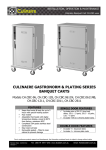
Download CULINAIRE BAIN MARIE HOT CUPBOARD
Transcript
INSTALLATION, OPERATION & MAINTENANCE Culinaire Bain Marie Hot Cupboard CH.CBMHx.U CULINAIRE BAIN MARIE HOT CUPBOARD Models: CH.CBMH3.U, CH.CBMH4.U, CH.CBMH5.U, CH.CBMH6.U, CH.CBMH7.U, CH.CBMH8.U FEATURES Grade 304 Double Skinned Stainless Steel Construction in No. 4 Satin Finish Double Skinned Construction with Air Insulation Digital Temperature Control Supports 1/1 Gastronorm Pans per Module Supports Gastronorm Pans up to 150mm Deep BSP Ball Outlet Water Valve Perforated Element Covers Easy-to-Remove Parts for Cleaning OPTIONAL FEATURES Gantry (check Data Sheets for more information) If Fitted Refer to Gantry Users Manual Radius corners to Bain Marie well UNDER BENCH FEATURES BSP Ball Inlet Water Valves Well Overflow 750W Elements per Module Under Mount Fittings GASTRONORM PANS (Sold Separately) 2/1, 25mm, 65mm, 100mm or 150mm 1/1, 25mm, 65mm, 100mm or 150mm 1/2, 25mm, 65mm, 100mm or 150mm 1/3, 25mm, 65mm, 100mm or 150mm 1/4, 25mm, 65mm, 100mm or 150mm 1/6, 25mm, 65mm, 100mm or 150mm 1/9, 25mm, 65mm, 100mm or 150mm 1/6 and 1/9 Gastronorm Pans Dividers Due to continuous product research and development, the information contained herein is subject to change without notice Revision Date: 12/04/2012 Version 4 Tel: 1300 79 1954 Web: www.stoddart.com.au Email: [email protected] INSTALLATION, OPERATION & MAINTENANCE Culinaire Bain Marie Hot Cupboard CH.CBMHx.U Table of Contents General Recommendations ................................................................................4 Important Information......................................................................................................4 General Safety .................................................................................................................4 Service ................................................................................................................4 Sharp Edges ........................................................................................................4 Power Cables .......................................................................................................4 Hot Surfaces ........................................................................................................4 Specifications ...................................................................................................5 Introduction ....................................................................................................................5 Product Overview .................................................................................................5 Technical.........................................................................................................................6 Code Explanation .................................................................................................6 Technical Specifications ........................................................................................6 Rating Plate .........................................................................................................8 Installation .......................................................................................................9 General Precautions .........................................................................................................9 Setting Up .....................................................................................................................10 Handling............................................................................................................ 10 Site Preparation ................................................................................................. 10 Unpacking ......................................................................................................... 10 Positioning......................................................................................................... 10 Element Covers .................................................................................................. 10 Dividers............................................................................................................. 11 Installing Shelves ............................................................................................... 11 Electrical (Qualified Personal Only) .................................................................................. 12 Power Supply..................................................................................................... 12 Grounding ......................................................................................................... 12 Plumbing (Qualified Technician Only)............................................................................... 13 Information ....................................................................................................... 13 Joinery Integration......................................................................................................... 14 Information ....................................................................................................... 14 Joinery Diagrams ............................................................................................... 14 Operation.......................................................................................................15 General Recommendations ............................................................................................. 15 Unit Operation ............................................................................................................... 16 Power ............................................................................................................... 16 Electronic Controllers .......................................................................................... 16 Carel Controller .................................................................................................. 16 Dixell Controller ................................................................................................. 17 Hot Cupboard Doors ........................................................................................... 18 BSB Ball Valves .................................................................................................. 18 Heat Lamps (with optional gantry feature)............................................................ 18 Gastronorm Pans ........................................................................................................... 18 Well and Cupboard Operation ......................................................................................... 19 Initial Start up.................................................................................................... 19 Water................................................................................................................ 19 Loading and Display ........................................................................................... 19 Food Temperature.............................................................................................. 20 Around the Well ................................................................................................. 20 After Hours....................................................................................................................20 Information ....................................................................................................... 20 Storage ............................................................................................................. 20 Due to continuous product research and development, the information contained herein is subject to change without notice Revision Date: 19/08/2013 Version 4 Tel: 1300 79 1954 Web: www.stoddart.com.au Page 1 Email: [email protected] INSTALLATION, OPERATION & MAINTENANCE Culinaire Bain Marie Hot Cupboard CH.CBMHx.U Cleaning........................................................................................................................ 21 Schedules .......................................................................................................... 21 Information ....................................................................................................... 21 Gastronorm Pans................................................................................................ 21 Dividers, Element Covers, Shelves ....................................................................... 21 External Surfaces ............................................................................................... 22 Well .................................................................................................................. 22 Cupboard .......................................................................................................... 22 Cupboard Doors ................................................................................................. 22 Maintenance...................................................................................................23 Routines........................................................................................................................ 23 Schedules .......................................................................................................... 23 Log Books.......................................................................................................... 23 Inspection ......................................................................................................... 23 Faults................................................................................................................ 23 Descaling the Well ......................................................................................................... 23 Information ....................................................................................................... 23 Element Protection......................................................................................................... 24 Information ....................................................................................................... 24 Stainless Steel Protection................................................................................................ 24 Cleaning ............................................................................................................ 24 Corrosion Protection ........................................................................................... 24 Surface Finish .................................................................................................... 24 Water Damage .............................................................................................................. 25 Information ....................................................................................................... 25 Access to Electrical Wiring and Mechanical Parts (Qualified Technician Only) ....................... 26 Electrical Junction Box ........................................................................................ 26 Electronic Controller Removal .............................................................................. 26 Fan Heater Unit.................................................................................................. 26 Hot Cupboard Doors ........................................................................................... 27 Replacing Elements ............................................................................................ 27 Carel Electronic Controller (Qualified Technician Only)....................................................... 28 Function ............................................................................................................ 28 Operation .......................................................................................................... 28 Parameters ........................................................................................................ 28 Alarms and Signals ............................................................................................. 29 Programming Instructions for the Controller ......................................................... 29 Summary of Parameters - PJEZ easy .................................................................... 30 Dixell Electronic Controller (Qualified Technician Only) ...................................................... 31 Function ............................................................................................................ 31 Operation .......................................................................................................... 31 Main Functions ............................................................................................... 32 Hot key programming .................................................................................... 32 Alarms and Signals ............................................................................................. 33 Programming Instructions for the Controller ......................................................... 33 Summary of High Temp Parameters – XR60CX ..................................................... 34 Summary of High Temp Parameters – XR60CX ..................................................... 35 Gastronorm Pans and Dividers............................................................................. 36 Water/Waste Connections ................................................................................... 36 Standing Waste.................................................................................................. 36 Shelves ............................................................................................................. 36 Heater Fan Unit.................................................................................................. 36 Elements ........................................................................................................... 36 Electrical Parts ................................................................................................... 36 Mechanical Parts ................................................................................................ 36 Due to continuous product research and development, the information contained herein is subject to change without notice Revision Date: 19/08/2013 Version 4 Tel: 1300 79 1954 Web: www.stoddart.com.au Page 2 Email: [email protected] INSTALLATION, OPERATION & MAINTENANCE Culinaire Bain Marie Hot Cupboard CH.CBMHx.U Servicing and Replacement Information Line .................................................................... 36 Troubleshooting..............................................................................................37 Electrical Diagram...........................................................................................38 Spare Parts List/Assembly................................................................................40 Warranty........................................................................................................41 Australian Warranty and Contact Details .......................................................................... 41 Australian Warranty Policy & Procedure............................................................................ 41 WARRANTY REQUEST FORM........................................................................................... 36 Due to continuous product research and development, the information contained herein is subject to change without notice Revision Date: 19/08/2013 Version 4 Tel: 1300 79 1954 Web: www.stoddart.com.au Page 3 Email: [email protected] INSTALLATION, OPERATION & MAINTENANCE Culinaire Bain Marie Hot Cupboard CH.CBMHx.U General Recommendations Important Information Carefully read this instruction booklet, as it contains important advice for safe installation, operation and maintenance. Keep this booklet on hand in a safe place for future reference by other operators or service technicians. All persons operating this appliance MUST read the operation section of this manual and be instructed by trained personal on the correct use of the appliance. If additional user manuals are needed talk to your distributor or visit the Culinaire website. Do NOT store or use gasoline or other flammable vapours or liquids in the vicinity of this or any other appliance. Qualified personnel, specifically trained in the following instructions, can perform installation and service of the machine. Disclaimer: The manufacturer and distributor cannot be held responsible or liable for any injuries or damages of any kind occurred to persons, appliances or others, due to abuse and misuse of this appliance in regards to installation, un-installation, operation, servicing or maintenance, or lack of conformity with the instructions indicated in this documentation. All appliances made by the manufacturer are delivered assembled, where possible, and ready to install. Any installation, un-installation, servicing, maintenance and access or removal of any parts, panels or safety barriers that is not permitted, does not comply in accordance to this documentation, or not performed by a TRAINED AND AUTHORISED SPECIALISTS will result in the IMMEDIATE LOSS OF THE WARRANTY. The manufacturer cannot be held responsible or liable for any unauthorized modifications. All modifications must be approved by the manufacturer in writing before initiating. All modifications or works performed to this appliance must be performed at all times by a TRAINED AND AUTHORISED SPECIALISTS. General Safety Service Stoddart, one of our agents, or a similarly qualified person(s) should carry out any and all repairs, maintenance and services. Any repair person(s) should be instructed to read the safety warnings within this manual before commencing work on these units. Do NOT remove any cover panels that may be on the appliance. Sharp Edges Steel cutting processes such as those used in the construction of this appliance result in sharp edges. Whilst any such edges are removed to the best of our ability it is always wise to take care when in contact with any edge. Particular care should be taken to avoid contact with any internal edge, all repair or maintenance person(s) prior to commencement of any servicing must read the maintenance section of this manual. Power Cables Ensure that any damaged power cord is replaced before further use. Hot Surfaces This unit can get very hot. Ensure everyone is aware that the appliance is operating and take care to avoid contact with hot surfaces. Due to continuous product research and development, the information contained herein is subject to change without notice Revision Date: 19/08/2013 Version 4 Tel: 1300 79 1954 Web: www.stoddart.com.au Page 4 Email: [email protected] INSTALLATION, OPERATION & MAINTENANCE Culinaire Bain Marie Hot Cupboard CH.CBMHx.U Specifications Introduction The Culinaire® Bain Marie Hot Cupboard has a high powered heavy duty Bain Marie that is designed to hold hot food at the optimum temperature in GN pans up to 150mm deep. The hot cupboard features a fan forced heating system, which offers energy saving efficiency, faster heat-up times and even heat distribution. Ready for connection to hot water inlet and waste with all valves supplied and fitted. Options: Standard stainless steel tops and Standard gantries are available with of without heat lamps; glass sides; roller doors; sneeze guards. Lift up, fold down side shelf. (Sold separately) WARNING! The Bain Marie MUST be used wet. Dry operation will void your warranty. Product Overview Configuration may vary according to model Due to continuous product research and development, the information contained herein is subject to change without notice Revision Date: 19/08/2013 Version 4 Tel: 1300 79 1954 Web: www.stoddart.com.au Page 5 Email: [email protected] INSTALLATION, OPERATION & MAINTENANCE Culinaire Bain Marie Hot Cupboard CH.CBMHx.U Technical Code Explanation Code Explanation CH Culinaire Heated CBMH Culinaire Bain Marie Hot Cupboard x 3 to 8 Module y U = Under Bench UR = Under Bench with Rounded Corners Technical Specifications SPECFICATIONS Model CH.CBMH3.U CH.CBMH4.U CH.CBMH5.U Height Width Depth Bain Marie Capacity Hot Cupboard Capacity Voltage Power Current Heated Fan Connection Temperature Range Water Connection Waste Connection 883mm 1100mm 750mm 3 x 1/1 Gastronorm Pans 4 x 1/1 Gastronorm Pans 220-240V, 50Hz 4500W 9.38 A 883mm 1440mm 750mm 4 x 1/1 Gastronorm Pans 6 x 1/1 Gastronorm Pans 220-240V, 50Hz 5250W 9.38 A 2250W 3 Phase, Neutral, Earth 65-90°C 13mm (½”) Diameter 40mm (1 ½”) Diameter 883mm 1780mm 750mm 5 x 1/1 Gastronorm Pans 8 x 1/1 Gastronorm Pans 220-240V, 50Hz 6000W 9.38 A SHIPPING Height Width Depth 900mm 1300mm 950mm 900mm 1640mm 950mm 900mm 11980mm 950mm CH.CBM7.U CH.CBM8.U SPECFICATIONS Model CH.CBM6.U Height Width Depth Bain Marie Capacity Hot Cupboard Capacity Voltage Power Current (average) Heated Fan Connection Temperature Range Water Connection Waste Connection 883mm 2120mm 750mm 6 x 1/1 Gastronorm Pans 10 x 1/1 Gastronorm Pans 220-240V, 50Hz 6750W 9.58 A 2250W 883mm 883mm 2460mm 2800mm 750mm 750mm 7 x 1/1 Gastronorm Pans 8 x 1/1 Gastronorm Pans 12 x 1/1 Gastronorm Pans 14 x 1/1 Gastronorm Pans 220-240V, 50Hz 220-240V, 50Hz 9,750W 10,500W 15.6 A 15.6 A 2 x 2250W 3 Phase, Neutral, Earth 65-90°C 13mm (½”) Diameter 40mm (1 ½”) Diameter SHIPPING Height Width Depth 900mm 2320mm 950mm 900mm 2660mm 950mm 900mm 3000mm 950mm Due to continuous product research and development, the information contained herein is subject to change without notice Revision Date: 19/08/2013 Version 4 Tel: 1300 79 1954 Web: www.stoddart.com.au Page 6 Email: [email protected] INSTALLATION, OPERATION & MAINTENANCE Culinaire Bain Marie Hot Cupboard CH.CBMHx.U Technical/Connection Diagram Plan View Front Elevation Section AA Due to continuous product research and development, the information contained herein is subject to change without notice Revision Date: 19/08/2013 Version 4 Tel: 1300 79 1954 Web: www.stoddart.com.au Page 7 Email: [email protected] INSTALLATION, OPERATION & MAINTENANCE Culinaire Bain Marie Hot Cupboard CH.CBMHx.U Rating Plate The rating plate of the appliance contains identification and technical data and is located inside the service door, on the front lower right side as indicated below. Due to continuous product research and development, the information contained herein is subject to change without notice Revision Date: 19/08/2013 Version 4 Tel: 1300 79 1954 Web: www.stoddart.com.au Page 8 Email: [email protected] INSTALLATION, OPERATION & MAINTENANCE Culinaire Bain Marie Hot Cupboard CH.CBMHx.U Installation General Precautions WARNING! Installation must comply with local electrical and health & safety requirements. Improper installation, adjustment, alteration, service or maintenance can cause property damage, injury or death. Do NOT use this appliance for other than its intended use. Do NOT store explosive substances such as aerosol cans with a flammable propellant in or near this appliance. Regulations require that all units be installed to the appropriate Australian standards. Regulations require that authorised persons carry out all electrical and plumbing work. Only use this appliance with voltage specified on the rating label. Be careful not to touch moving parts. Important! Ensure that a qualified technician sets up and installs this unit. Due to continuous product research and development, the information contained herein is subject to change without notice Revision Date: 19/08/2013 Version 4 Tel: 1300 79 1954 Web: www.stoddart.com.au Page 9 Email: [email protected] INSTALLATION, OPERATION & MAINTENANCE Culinaire Bain Marie Hot Cupboard CH.CBMHx.U Setting Up Handling Use suitable means to move the appliance: eg. A lift truck or fork pallet trucks (the forks should reach more than halfway beneath the appliance). Site Preparation Ensure the site is level and properly cleaned. Ensure that all joinery or benches for the unit are made before installation. Unpacking Check the unit for damage before and after unpacking. If unit is damaged, contact the distributor and manufacturer. Wear protective gloves to unpack the appliance from the box. The unit is supplied fully assembled. The shelves are packed unassembled. Gastronorm pans and dividers are packed separately. Unpack and visually inspect the unit for damage or missing parts. Report any problems to the distributor or manufacturer. Remove all protective plastic film, tapes, ties and packers before installing and operating. Clean off any glue residue left over from the protective plastic film. Wipe all surfaces with a clean, sanitised cloth. Positioning Position the unit before setting up shelves, dividers and power supply Ensure the unit is positioned on a level surface to allow the well water to drain properly and to cover the bottom of the pans evenly. Ensure the unit is NOT positioned where an exhaust fan or air conditioning is above the unit. Do NOT install the operating hot cupboard next to any heat source or grease-emitting appliance (i.e. fryers). Allow approximately 300mm gap. Element Covers Element covers are placed over the top of the elements for protection. When installing, ensure no water is in the well, water maybe hot and burn persons. Element Without Cover Element With Cover Due to continuous product research and development, the information contained herein is subject to change without notice Revision Date: 19/08/2013 Version 4 Tel: 1300 79 1954 Web: www.stoddart.com.au Page 10 Email: [email protected] INSTALLATION, OPERATION & MAINTENANCE Culinaire Bain Marie Hot Cupboard CH.CBMHx.U Dividers The module dividers are provided with the unit. The 1/6, 1/9 dividers are sold separately. 1/6, 1/9 dividers sit on the top of the module dividers and the top of the well. To setup, clip the length divider(s) into width divider(s). Bain Marie Without Divider Bain Marie With Divider Installing Shelves Shelf Clips Important! Do NOT use PLIERS or CRIMPING tools when installing the shelf clips. Shelf clips will lose their tension. The shelf clips clip into the rail. The shelf support pin needs to be facing up Squeeze the pin to fit the bottom of the clip in All four pins for the shelf need to be at the same height for a level shelf Fitting the Shelves The outer frame of the shelf fits over the shelf support pin Due to continuous product research and development, the information contained herein is subject to change without notice Revision Date: 19/08/2013 Version 4 Tel: 1300 79 1954 Web: www.stoddart.com.au Page 11 Email: [email protected] INSTALLATION, OPERATION & MAINTENANCE Culinaire Bain Marie Hot Cupboard CH.CBMHx.U Electrical (Qualified Personal Only) WARNING! This unit MUST be installed in accordance with AS/NZS 60335.1 and complies with local laws Power Supply It is recommended that the unit is hard wired. No power cord or plug is supplied with the unit. Ensure that all power supplies are switched OFF before hard wiring the unit. Ensure that there is an isolation switch installed near the unit. To connect the power, the unit has a terminal block in the electrical junction box. The power switches and electronic controller are the face of the electrical junction box. Units can be different phases, check the electrical ratings on the rating label located near the terminal block or in the specification manual. Ensure that all wiring is placed out of the harms way and can not be damaged when the unit is in operation. WARNING! Do NOT overload the power supply. See the rating label for the power, voltage and current supply. Grounding This unit MUST be grounded. A grounding connection is supplied on the terminal block. All electrical wiring within the unit is correctly grounded when leaving the factory. Due to continuous product research and development, the information contained herein is subject to change without notice Revision Date: 19/08/2013 Version 4 Tel: 1300 79 1954 Web: www.stoddart.com.au Page 12 Email: [email protected] INSTALLATION, OPERATION & MAINTENANCE Culinaire Bain Marie Hot Cupboard CH.CBMHx.U Plumbing (Qualified Technician Only) WARNING! This unit must be installed in accordance with AS/NZS 3500.1 Important! This unit must be operated on potable water. If the water has a high mineral content, pretreatment may be necessary or your warranty could be voided. Information The unit is supplied with a G 1½” BSP drainage connection and a standing waste. The BSP valve does not need to be connected if the standing waste is used. The wastewater connection screws into the drainage connection. The wastewater MUST be tested for leakages after being installed. The standing waste plugs into the drain hole. The unit MUST be on a level surface for the water to drain properly. Before use, the water purity needs be checked; high mineral water can corrode the elements and taint the water/food. If needed, a filtration system should be installed. The unit is supplied with a G ½” BSP Water Connection for filling the well. The water valve MUST be tested for leakages after being installed. The water connection can be connected to either a hot or cold water supply (hot produces quicker start up times). It is recommended that the Bain Marie is connected to the water mains and drained to a tundish. Waste Connection Standing Waste Water Connection Drainage & Water Connection Well Drain Due to continuous product research and development, the information contained herein is subject to change without notice Revision Date: 19/08/2013 Version 4 Tel: 1300 79 1954 Web: www.stoddart.com.au Page 13 Email: [email protected] INSTALLATION, OPERATION & MAINTENANCE Culinaire Bain Marie Hot Cupboard CH.CBMHx.U Joinery Integration Information Prior to manufacturing, check specification manual for unit sizes. Joinery needs to support the weight of the unit. Ensure all joinery is made to Australian or local regulations. Ensure the bench allows for access to the electrical junction box, and the water and waste connections for maintenance. Ensure the joinery is level to allow the water to drain properly. If more information is required contact the distributer or manufacturer. Joinery Diagrams Due to continuous product research and development, the information contained herein is subject to change without notice Revision Date: 19/08/2013 Version 4 Tel: 1300 79 1954 Web: www.stoddart.com.au Page 14 Email: [email protected] INSTALLATION, OPERATION & MAINTENANCE Culinaire Bain Marie Hot Cupboard CH.CBMHx.U Operation General Recommendations When using any electrical appliance, safety precautions should always be observed. Our appliances have been designed to give high performance. Hence, the appliance must be used exclusively for the purpose for which it has been designed. Read these instrucitons carefully and retain for future reference. Important! This appliance should not be operated by person(s) (including children) with reduced physical, sensory or mental capabilities, or lack of experience or knowledge, unless they have been given supervision or instruction concerning the safe use of the appliance by person(s) responsible for their safety. All appliances MUST be installed according to the procedures stated in the installation section of this manual. In the case of new personnel, training is to be provided in advance. Do NOT use this appliance for any other purpose than its intended use. Do NOT store explosive substances such as aerosol cans with a flammable propellant in or near this appliance. Ensure element covers are installed before switching the elements ON. Keep fingers out of "pinch point" areas. Clearances between the doors, pans and panels are necessarily small. This appliance is NOT waterproof. Do NOT use hoses or harmful materials on the appliance. If the power supply cord becomes damaged, it must be replaced the by manufacturer, an authorised service agent or similarly qualified persons to avoid a hazard. Be careful not to touch moving parts. The surfaces of this unit are HOT when in operation. Signage should be displayed for personal and customers. Ensure element covers are installed before switching the elements ON. Do NOT use sharp objects to activate controls. If any fault is detected, disconnect the appliance from the mains and call the service agent. Do NOT use the appliance in an explosive atmosphere. The manufacturer declines any liability for damages to persons and/or things due and to an improper/wrong and/or unreasonable use of the unit. WARNING! The water in the well and the surfaces of this unit are HOT when operating. Take caution and do NOT place any part of the body in the water. Due to continuous product research and development, the information contained herein is subject to change without notice Revision Date: 19/08/2013 Version 4 Tel: 1300 79 1954 Web: www.stoddart.com.au Page 15 Email: [email protected] INSTALLATION, OPERATION & MAINTENANCE Culinaire Bain Marie Hot Cupboard CH.CBMHx.U Unit Operation Power The Bain Marie and the hot cupboard have separate power switches that allow either section to operate when needed. The Bain Marie can be switched ON or OFF with the BAIN MARIE button. The hot cupboard can be switched ON or OFF with the HOT CUPBOARD button. The POWER button is a protection switch. No other switch can operate if the POWER button is OFF. Electronic Controllers The bain marie and the hot cupboard have separate electronic controllers, both operate the same. The bain marie/hot cupboard electronic controller will switch ON when the bain marie/hot cupboard power button is switched ON. The preset temperature for the bain marie and the hot cupboard when leaving the factory are 70°C and 85°C respectively. Instructions for adjusting the temperature are below. The temperature range for both controllers is between 65°C and 95°C. Bain marie operational modes require different temperatures, check the operational modes section for suggested temperature for the mode you need. The temperature displayed on the bain marie controller is the water temperature. The hot cupboard controller is the air temperature within the cupboard. Neither is the food temperature. Carel Controller Set Point Temperature PRESS "SET" & HOLD For 1 Second “SET POINT" Value will be displayed Button PRESS ARROW "UP" or "DOWN” to set the desired value. ** 1 2 UP Set PRESS "SET" to confirm the value 3 Down Function Normal Operation Pressing the button alone more than 3 s: switch ON/OFF - 1 s.: display/set the set point - mute audible alarm (buzzer) - more than 3 s: activates/ deactivates the defrost Due to continuous product research and development, the information contained herein is subject to change without notice Revision Date: 19/08/2013 Version 4 Tel: 1300 79 1954 Web: www.stoddart.com.au Page 16 Email: [email protected] INSTALLATION, OPERATION & MAINTENANCE Culinaire Bain Marie Hot Cupboard CH.CBMHx.U Dixell Controller The temperature can be set between 65°C and 95°C, setting the temperature is below. Different modes require different temperatures. The temperature probe only measures the temperature of the water/air, NOT the food temperature. Due to continuous product research and development, the information contained herein is subject to change without notice Revision Date: 19/08/2013 Version 4 Tel: 1300 79 1954 Web: www.stoddart.com.au Page 17 Email: [email protected] INSTALLATION, OPERATION & MAINTENANCE Culinaire Bain Marie Hot Cupboard CH.CBMHx.U Important! After switching ON, allow 45 minutes for the unit to reach the operating temperature before placing the PRE-HEATED/COOKED food into the unit. Hot Cupboard Doors The cupboard doors are OPENED and CLOSED using the door handles. Ensure that the doors are operated correctly as they become hot when the unit is in operation. BSB Ball Valves The BSB ball valves are a part of the water and waste connections located under the unit. The valves can be OPENED or CLOSED using the handle. The water connection allows water to fill the well when the valve is OPEN (under bench units only). The waste connection allows the water to drain out of the well when the valve is OPEN. Heat Lamps (with optional gantry feature) Heat lamps switches are pre-installed into all units, with or without the gantry feature. Heat Lamps can be switched ON or OFF with the TOP GANTRY and BOTTOM GANTRY button. For more information on the heat lamps check the gantry user manuals. Gastronorm Pans All gastronorm pans and extra dividers are sold separately. Ensure all dividers are secure before placing in the pans. All food placed in the pans MUST be pre-heated/cooked. Pans should not be overloaded. Ensure only 1 type of product is placed in each pan to prevent cross contamination. If more pans are needed, contact your distributor or manufacturer. Do NOT replenish food in old pans, replace and clean pans before using again. Each module can hold one 1/1 pan, two 1/2 pans, three 1/3 pans, four 1/4 pans, six 1/6 pans and nine 1/9 pans. 2/1 pans can also be fitted over 2 modules. Pan depths are 25mm, 65mm, 100mm and 150mm contact your distributer about the best possible depth for the product you intent to display. For 1/6 and 1/9 Gastronorm pans, extra dividers needed to be placed. Due to continuous product research and development, the information contained herein is subject to change without notice Revision Date: 19/08/2013 Version 4 Tel: 1300 79 1954 Web: www.stoddart.com.au Page 18 Email: [email protected] INSTALLATION, OPERATION & MAINTENANCE Culinaire Bain Marie Hot Cupboard CH.CBMHx.U Well and Cupboard Operation Initial Start up Before switching ON the unit, ensure the unit is installed correctly and element covers, dividers and shelves are placed in the unit. Fill the bain marie with water to the overflow then switch the power to both sections of the unit ON. Ensure that the electronic controller is ON and the well and cupboard are heating to operating temperature. To check all the elements are heating up the water, bubbles should appear around the elements If problems occur, contact the distributer or manufacturer. Leave the bain marie to operate with water in the well for 3 - 4 hours and the hot cupboard for 1 - 2 hours to remove any fumes or odours. Check the water level of the bain marie hourly. Drain the well and allow the unit to cool. After, clean the whole unit, including the gastronorm pans. Your unit is now ready to operate. Water The element covers should be placed over the elements before filling the well. The well must be filled with clean, fresh water before using in the wet and steam modes. Dirty water will taint the food and corrode the elements. The well can be filled via the water connection or bucket. Do NOT switch ON the unit until the well is at the water level required. Hot or cold water can be used. Hot water will allows less boiling time and saves power. Water MUST not be recycled and the well should be refilled at the start of each work day. After being in the well, all water MUST be treated as waste water. Do NOT drink and serve to persons. Water with high mineral content needs be filtered to prevent element corrosion. WARNING! The water in the well is HOT when operating. Take caution NOT to place any part of the body in the water. Loading and Display Ensure that the bain marie and/or hot cupboard are switched ON and have reached operating temperature before placing any food in the unit. All food placed in the well and cupboard MUST be pre-heated/cooked. Ensure the heat vents in the hot cupboard are NOT covered. Air flow restrictions will change the temperature within the cupboard. Cupboard doors should be shut at all times to maintain uniform temperature. Only gastronorm pans are to be placed in the well. Serving items and extra gastronorm pans can be placed in the hot cupboard. Important! All food MUST be pre-heated/cooked before placing in the unit. Attempting to cook food in this unit can lead to food poisoning. Due to continuous product research and development, the information contained herein is subject to change without notice Revision Date: 19/08/2013 Version 4 Tel: 1300 79 1954 Web: www.stoddart.com.au Page 19 Email: [email protected] INSTALLATION, OPERATION & MAINTENANCE Culinaire Bain Marie Hot Cupboard CH.CBMHx.U Food Temperature All food MUST be pre-heated/cooked before placing in the unit. Attempting to cook food in this unit can lead to food poisoning. Ensure the well is maintaining the food temperature over 65°C. The temperature reached on the temperature gauge is the water/air temperature, NOT the food temperature. It is important to regularly monitor the food temperature in the Bain Marie and the Hot Cupboard. Important! This unit is not designed to cook products, it only maintains them above the regulated 65°C serving temperature. Around the Well Ensure the benches around the unit are cleaned continuously to prevent contaminants entering the pans. When operating, the surfaces may be hot. Signage should be displayed for personal and customers to ensure no one will burn themselves. Water MUST not be recycled and the well should be refilled at the start of each workday. After being in the well, all water MUST be treated as waste water. Do NOT drink and serve to persons. Water with high mineral content needs be filtered to prevent element corrosion. After Hours Information This unit is NOT designed to store product after hours. The unit MUST be switched OFF. All pans should be cleaned and placed in night storage. No pans should be left in the well. Drain the well, no water should remain in the well. If the unit is moved for night storage, ensure the castors are locked (island buffet/mobile units only). Storage All storage of food should comply with local health standards and regulations. Due to continuous product research and development, the information contained herein is subject to change without notice Revision Date: 19/08/2013 Version 4 Tel: 1300 79 1954 Web: www.stoddart.com.au Page 20 Email: [email protected] INSTALLATION, OPERATION & MAINTENANCE Culinaire Bain Marie Hot Cupboard CH.CBMHx.U Cleaning WARNING! Switch the unit OFF at the main power supply before cleaning. WARNING! Ensure the unit has cooled before attempting any cleaning. Allow 30 – 60 minutes. Schedules After use, the gastronorm pans should be cleaned STRAIGHT AWAY. The unit should be cleaned at the end of the EVERY WORK DAY. Information Cleaning is recommended for health and safety purposes and to prolong the life of the unit. All liquids around the unit MUST be cleaned up straight away. Ensure the benches around the unit are cleaned continuously to prevent contaminants entering the well (under bench units). All food product MUST be removed from the unit before cleaning. Do NOT use abrasive pads or cleaners on the stainless steel or any other metal parts of the unit. Do NOT use industrial chemical cleaners or caustic based cleaners, many will damage the metals and plastics used on this unit. The well MUST be drained before cleaning. Ensure the waste connection is left OPENED to allow sufficient drainage while cleaning the well. Ensure the waste connection is left OPEN to allow sufficient drainage while cleaning. Shelves, dividers and element covers are able to be removed for cleaning. The gastronorm pans MUST be removed. Do NOT remove shelf clips. When drying, metal surfaces should be wiped with a soft cloth in the same direction as grained polish. Ensure all due care is taken when cleaning the elements, they can become damaged. Do NOT remove any screws for cleaning. All internal sections of the unit are to be cleaned by a qualified technician. For maintenance of stainless stain surfaces, check the maintenance guide for more information. IMPORTANT! Some commercial stainless stain cleaners leave residue or film on the metal that may entrap fine particles of food, thus deeming the surface not FOOD SAFE. Gastronorm Pans Clear the pans of food and/or any food scraps before cleaning. Pans can be cleaned in a dishwasher or kitchen sink with warm soapy water. Thoroughly wipe dry after cleaning, do NOT allow to air dry. Dividers, Element Covers, Shelves All parts can be cleaned in a kitchen sink with warm soapy water. Thoroughly wipe dry with a soft cloth after cleaning, do NOT allow to air dry. Due to continuous product research and development, the information contained herein is subject to change without notice Revision Date: 19/08/2013 Version 4 Tel: 1300 79 1954 Web: www.stoddart.com.au Page 21 Email: [email protected] INSTALLATION, OPERATION & MAINTENANCE Culinaire Bain Marie Hot Cupboard CH.CBMHx.U External Surfaces Clean the surfaces with warm (not hot) soapy water and a sponge. After cleaning, thoroughly wipe the surfaces dry with a soft cloth. Do NOT let water pool on any surface, check crevices and folds. Take care around the switches and controller as there is electrical wiring inside. WARNING! The external surfaces of this unit are NOT waterproof, do NOT hose. Well Clean the well and elements with warm (not hot) soapy water and a sponge. After cleaning, flush the well with water. Thoroughly wipe the well and elements dry with a soft cloth. Do NOT let water pool in the well, check crevices and folds. If possible, vacuum the well with a wet and dry vacuum cleaner. Important! Elements can be damaged when cleaning. Ensure all due care is taken. Cupboard Clean the cupboard with warm (not hot) soapy water and a sponge. After cleaning, thoroughly wipe the cupboard dry with a soft cloth. Do NOT let water pool on the unit, check crevices and folds. Take care around the heat vents, use as minimal water as possible. Cupboard Doors Clean the cupboard doors with warm (not hot) soapy water and a sponge. After cleaning, thoroughly wipe the cupboard dry with a soft cloth. Do NOT let water pool on the unit, check crevices and folds. Ensure both sides of the doors are cleaned. Tracks do NOT need to be cleaned. Due to continuous product research and development, the information contained herein is subject to change without notice Revision Date: 19/08/2013 Version 4 Tel: 1300 79 1954 Web: www.stoddart.com.au Page 22 Email: [email protected] INSTALLATION, OPERATION & MAINTENANCE Culinaire Bain Marie Hot Cupboard CH.CBMHx.U Maintenance Routines Schedules To maintain optimal performance, maintenance and cleaning schedules must be regular and thorough. After use, the gastronorm pans should be cleaned STRAIGHT AWAY. Fill the well with clean water at the START of every work day and drain the well at the END of every work day. The unit should be cleaned at the end of the EVERY WORK DAY. Descale the well MONTHLY. Log Books Log books should be kept for all cleaning and maintenance of this unit. Inspection Surfaces should be checked at least once a week for damage or deterioration. As part of the maintenance, a qualified technician MUST check the controls, mechanical parts and electrical wiring for damage, deterioration or need of adjustment. Faults Not repairing small faults immediately can cause a complete breakdown. If any small faults occur, have them attended to promptly by a qualified technician. All faults should be reported to the distributor and manufacturer. WARNING! If any electrical wires are damaged, the unit must NOT be switched ON until the parts have been fixed as injury or death can occur. Descaling the Well Information Descaling is recommended for heath and safety purposes and to prolong the life of the unit. The well MUST be descaled monthly to remove any scaling and built-up in the well and on the elements. Element covers should be descaled at the same time as the well. To descale, a decaling solution needs to be purchased. The descaling solution should be used as per directions on the container. Remove all food and pans from the well before descaling. Ensure the well is rinsed and thoroughly cleaned after descaling. Due to continuous product research and development, the information contained herein is subject to change without notice Revision Date: 19/08/2013 Version 4 Tel: 1300 79 1954 Web: www.stoddart.com.au Page 23 Email: [email protected] INSTALLATION, OPERATION & MAINTENANCE Culinaire Bain Marie Hot Cupboard CH.CBMHx.U Element Protection Information Every day, the well should be filled with clean water. A lemon slice or a few drops few drops of lemon juice should be added to the water daily. After use, adding a commercial cleaning agent that contains citric/oxalic/nitric/phosphoric and boil for 45 minutes helps to prolong the life of the Bain Marie. Do NOT use cleaning agents with chlorides or other harsh chemicals as this can cause corrosion. Do NOT fill the well with cold water if the elements are hot. Water with high mineral content needs be filtered. When cleaning, clean the elements properly and allow to dry before switching the unit back ON. Check the operation manual for more information. Stainless Steel Protection Cleaning For cleaning the stainless steel, check the cleaning section. All metal surfaces should be checked while cleaning for damage, scuffs or scapes as these can lead to rust and further damage to the product. Corrosion Protection Stainless steel exhibits good resistance to corrosion however, if not properly maintained stainless steel can rust. Any sign of mild rust or corrosion should be thoroughly cleaned with warm soapy water and dried as soon as possible. NEVER use abrasive pads or cleaners for cleaning. Medium rust or corrosion can treated with a commercial cleaning agent that contains citric/oxalic/nitric/phosphoric. Do NOT use cleaning agents with chlorides or other harsh chemicals as this can cause corrosion. After treatment, wash with warm (not hot) soapy water and dry thoroughly. Thoroughly wipe the surfaces dry after cleaning and do NOT let water pool on the unit. Check crevices and folds for pooling. If an abrasive product is used while cleaning, thoroughly dry the unit and leave in an open or oxidised area for the stainless steel protective layer to replenish. When using, ensure all liquids and moisture is cleaned up straight away. Food liquids such as juices from vegetables and fruits should NOT be left on preparation surfaces. Do NOT leave items on the stainless steel such as cutting boards, rubber mats and bottles. Surface Finish To protect the polish, stainless steel should be dried by wiping a dry soft cloth in the same direction as grained polish. For NON-food contact surfaces, a light oil can be wiped on the surfaces with a cloth to enhance the stainless steel surface. Wipe in the direction of the grain. Some commercial stainless stain cleaners can leave residue or film on the metal; this may trap fine particles of food on the surface, thus deeming the surfaces not food safe. Due to continuous product research and development, the information contained herein is subject to change without notice Revision Date: 19/08/2013 Version 4 Tel: 1300 79 1954 Web: www.stoddart.com.au Page 24 Email: [email protected] INSTALLATION, OPERATION & MAINTENANCE Culinaire Bain Marie Hot Cupboard CH.CBMHx.U Water Damage Information Water damage to the electrical and mechanical parts of unit can occur through hosing on or around the unit. Improper cleaning of the unit can lead to water damage. If water damage occurs allow the unit to dry and ensure the unit is checked by a qualified technician before switching the unit ON. All water damage that is not due to construction or mechanical faults is not covered by warranty. WARNING! If any water damage occurs, the unit must NOT be switched ON. Due to continuous product research and development, the information contained herein is subject to change without notice Revision Date: 19/08/2013 Version 4 Tel: 1300 79 1954 Web: www.stoddart.com.au Page 25 Email: [email protected] INSTALLATION, OPERATION & MAINTENANCE Culinaire Bain Marie Hot Cupboard CH.CBMHx.U Access to Electrical Wiring and Mechanical Parts (Qualified Technician Only) WARNING! Switch the unit OFF at the main power supply before any maintenance or servicing. Important! All due care has been taken in manufacturing, but there may be SHARP EDGES around the internal sections. Electrical Junction Box The electrical junction box has the switches on the face, and contains main wiring to the unit inside. 1. Unscrew the Fixing screws on the electrical junction box. 2. Pull out panel slowly. Electronic Controller Removal 1. Access the electrical junction box. 2. Unplug wiring loom. 3. Remove digital controller face panel by gently levering it off. 4. Unscrew on the front of the controller face. 5. Remove the electronic controller Fan Heater Unit The cupboard should be allowed to cool for 30 minutes before attempting to remove. Access to the fan heater unit is via the sidewall panel in the hot cupboard interior. Access to the fan heater units allows the fans, elements and thermostat to be replaced. The fan heater unit is a NON SERVICABLE item, the whole unit should be returned to Stoddart for servicing and replaced by a new unit. The thermostat can be changed when accessing the fan heater unit. It is a safety device to stop the fan heater unit from overheating; the factory preset cut-off temperature is 120°C. 1. Remove the shelves and hot cupboard doors. 2. Unscrew the screws to the sidewall panel and pull the fan heater unit out slowly. 3. Unscrew the screws that are connecting the sidewall panel to the fan heater unit and separate. 4. Cut the wires to the unit 5. Reverse the direction to install a new heater fan Side Panel Screws Fan Heater Screws Due to continuous product research and development, the information contained herein is subject to change without notice Revision Date: 19/08/2013 Version 4 Tel: 1300 79 1954 Web: www.stoddart.com.au Page 26 Email: [email protected] INSTALLATION, OPERATION & MAINTENANCE Culinaire Bain Marie Hot Cupboard CH.CBMHx.U Hot Cupboard Doors The hot cupboard doors are top mounted. The doors are held in place by a wall panel at the top of the hot cupboard interior. 1. Remove the shelves. 2. Unscrew the screws to the side panel and the door rail panel holding the doors in place and remove. 3. Place two hands on both sides on the door, lift up and swing out. Repeat for other door. Screw (same on other side) Door Rail Panel WARNING! Ensure the bottom panel of the well is lifted slowly. Some electrical parts have short wires. Replacing Elements Drain the water out of the well before attempting any replacement. If needed, elements should be allowed to cool for 60 minutes before placing hands in the well to remove. All new elements MUST be sealed with silicon to ensure the well is water proofed. The washer MUST be replaced. 1. Drain the water and remove the element covers. 2. Access the side panel. 3. Unscrew the screws to the element wiring. Remove the wiring. 4. Unscrew the nuts on the back of the element and remove the element and the washer. 5. Clean off the silicon on the around the element hole. 6. Place a new washer on the element and place them in the element hole. 7. Silicon the washer into place to ensure that the well is water proofed. 8. Screw the nut back on the washer as tight as possible. 9. Connect the wiring to the element. Ensure the screws are on tightly. Side Panel Element nuts. Silicon needed on the inside when replacing. Screws . Screws . Element wiring connected here Electrical Junction Box . Due to continuous product research and development, the information contained herein is subject to change without notice Revision Date: 19/08/2013 Version 4 Tel: 1300 79 1954 Web: www.stoddart.com.au Page 27 Email: [email protected] INSTALLATION, OPERATION & MAINTENANCE Culinaire Bain Marie Hot Cupboard CH.CBMHx.U Carel Electronic Controller (Qualified Technician Only) Button Function 1 Up – ON / OFF 2 Set 3 Down Icon Function 4 5 6 Compressor Fan Defrost Auxiliary output (AUX) Alarm Clock (RTC) Digits 7 8 9 10 Normal Operation Pressing the button alone more than 3 s: switch ON/OFF - 1 s.: display/set the set point - more than 3 s: access parameter setting menu (enter password ‘22’) - mute audible alarm (buzzer) - more than 3 s: activates/ deactivates the defrost Normal Operation ON OFF on off on off on off Start up for 1 s: RESET current EZY set for 1 s: display firmware version code Pressed together (2 and 3) activates parameter RESET procedure Blink request request request Start up ON ON ON - - - - all - No Alarm - - ON - Function The electronic controller controls and displays the internal temperature. The electronic controller signals problems with the unit. Changing settings should be completed by a qualified technician. Operation For general operation, the electronic controller requires no initial setup or additional programming. The preset temperature setting, controls the product temperature between 2°C and 4°C. If the temperature probe is damaged, runs the compressor for 5 minutes then turn off for 15 minutes, and repeats, to keep the product at a refrigerated around the set point temperature. Parameters There are 2 types of parameters frequent (type F) and configuration (type C) Type C parameters need a password (default =22) to access to prevent accidental or unauthorised access. Due to continuous product research and development, the information contained herein is subject to change without notice Revision Date: 19/08/2013 Version 4 Tel: 1300 79 1954 Web: www.stoddart.com.au Page 28 Email: [email protected] INSTALLATION, OPERATION & MAINTENANCE Culinaire Bain Marie Hot Cupboard CH.CBMHx.U Alarms and Signals When an alarm is activated, the display shows the corresponding message that flashes alternating with the temperature; if fitted and enabled, the buzzer and the alarm relay are also activated. All the alarms have automatic reset (that is, they stop when the causes are no longer present) Pressing the SET button mutes the buzzer, while the code displays and the alarm relay only go off when the causes of the alarm have been resolved. The alarm codes are shown in the table below. Alarm code Buzzer & alarm relay LED Description Parameters involved E0 LO HI EE EF EtC Active Not active Not active Not active Not active Not active ON ON ON ON ON ON Probe 1 error =control Low temperature alarm High temperature alarm Unit parameter error Operating parameter error Clock alarm [AL] [Ad] [AH] [Ad] If bands active Programming Instructions for the Controller Set Point All Parameters PRESS "SET" & HOLD For 1 Second “SET POINT" Value will be displayed PRESS & HOLD "SET" for approx 5 seconds PRESS ARROW "UP" or "DOWN” to set the desired value. ** "PS" will be displayed PRESS "SET" to confirm the value PRESS 'SET" then “ARROW UP" till the password value "22" is displayed PRESS "SET" to confirm Frequent (F) Parameters PRESS & HOLD "SET" for approx 5 seconds "PS" will be displayed A) PRESS “ARROW UP" & "DOWN" to select the code of the parameter to be changed. eg. rd = differential "PS" will be displayed A) PRESS “ARROW UP” or “DOWN” to select the parameter to be changed, eg rd = differential B) PRESS "SET” The Value Set for this parameter will be displayed B) PRESS “SET” The Value Set for this parameter will be displayed C) PRESS “ARROW UP" & "DOWN" to set the desired value. C) PRESS ARROW “UP" or "DOWN" to set the desired value. ** D) PRESS "SET" to confirm the value D) PRESS "SET" to confirm the value REPEAT A-D Until all desired parameters have been set. REPEAT A-D Until all desired parameters have been set. PRESS & HOLD "SET" until temp is displayed (approx 5 seconds) To confirm all changes PRESS & HOLD "SET" until temp is displayed (approx 5 seconds) to confirm all changes Due to continuous product research and development, the information contained herein is subject to change without notice Revision Date: 19/08/2013 Version 4 Tel: 1300 79 1954 Web: www.stoddart.com.au Page 29 Email: [email protected] INSTALLATION, OPERATION & MAINTENANCE Culinaire Bain Marie Hot Cupboard CH.CBMHx.U Summary of Parameters - PJEZ easy Code Parameters Unit Type Min. Max. Def. Changed PS /2 /4 /5 /6 /C1 Password Probe measurement stability Select probe/input displayed (*) Select ºC/ºF (0 = ºC, 1 = ºF) Decimal point (0=enabled, 1=disabled) Calibration of probe 1 ºC/ºF F C F C C F 0 1 1 0 0 -50 200 15 3 1 1 +50 22 4 1 0 0 0 22 4 1 0 0 0 St r1 r2 r3 r4 rd Temperature set point Minimum set point allowed to the user Maximum set point allowed to the user Mode 0=direct with defrost, 1=direct, 3=reverse Automatic night-time set point variation Control differential (hysteresis) ºC/ºF ºC/ºF ºC/ºF ºC/ºF ºC/ºF F C C C C F r1 -50 r1 0 -50 0 r2 r2 200 2 50 19 4 -50 90 0 3 2 70 65 90 0 3 4 AO AL AH Ad Alarm and fan differential Low temperature alarm threshold/deviation (AL=0 alarm disabled) High temperature alarm threshold/deviation (AH=0 alarm disabled) Low & high temperature alarm delay Configuration of digital input 0= input not active 1= ext. alarm, instant (A=0) or delayed (A7>0) 2= enable defrost (open=disabled) 3= start defrost on closing 4= curtain switch or night-time operation (open= normal setpoint) 5= remote ON/OFF (open= OFF) 6= AUX output control (H1=3) (open= AUX de-energ.) 7= AUX output (H1=3) +FAN OFF control (closed) (open = AUX energised) 8= AUX output (H1=3) +FAN OFF (closed) + COMP-OFF control (closed); (open = AUX energised) 9= select direct/reverse operation; r3=0=> open= direct +defrost; closed= reverse r3=1/2=>open=direct; closed= reverse 10= condenser probe 11=product probe External alarm detection delay Enable alarm ‘Ed’ :end defrost by timeout (1=enabled) High condenser temperature alarm High cond. Temp. alarm differential High cond. Temp. alarm delay ºC/ºF ºC/ºF ºC/ºF min C F F C -20 -50 50 0 20 250 250 199 2 0 0 0 10 0 0 0 - C 0 11 0 0 min ºC/ºF ºC/ºF min C C C C C 0 0 -50 0.1 0 199 1 250 20 250 0 0 70 5 0 0 0 70 5 0 - C 0 207 1 1 - C 0 3 0 0 - C 0 2 1 1 - C F C 0 0 0 1 199 4 0 1 0 0 0 A4 A7 A8 Ac AE Acd H0 H1 H2 H4 H5 EZY Serial address AUX output configuration 0=no function associated with the output 1=alarm output usually energised 2=alarm output usually de-energised 3=auxiliary output driven by dig. Input (A4=6/7/8) Dig. Input OPEN=AUX de-energised Dig. Input CLOSED=AUX energised Enable keypad (0= disabled, 1= enabled, 2- enabled except for ON/OFF function) Disable buzzer (0=enabled, 1=disabled) Key Identification code from supervisor Select Easy Set according to the model, see manual (see notes) Due to continuous product research and development, the information contained herein is subject to change without notice Revision Date: 19/08/2013 Version 4 Tel: 1300 79 1954 Web: www.stoddart.com.au Page 30 Email: [email protected] INSTALLATION, OPERATION & MAINTENANCE Culinaire Bain Marie Hot Cupboard CH.CBMHx.U Dixell Electronic Controller (Qualified Technician Only) : To display target set point; in programming mode it selects a parameter or confirm an operation. (DEF): To start a manual defrost. (UP): To see the max. stored temperature; in programming mode it browses the parameter codes or increases the displayed value. (DOWN): To see the min stored temperature; in programming mode it browses the parameter codes or decreases the displayed value. To switch the instrument off, if onF = oFF. Not enabled KEY COMBINATIONS: + To lock & unlock the keyboard. . + + To enter in programming mode. To return to the room temperature display. Function The electronic controller controls and displays the internal temperature. The electronic controller signals problems with the unit. Changing settings should be completed by a qualified technician. Operation For general operation, the electronic controller requires no initial setup or additional programming. Due to continuous product research and development, the information contained herein is subject to change without notice Revision Date: 19/08/2013 Version 4 Tel: 1300 79 1954 Web: www.stoddart.com.au Page 31 Email: [email protected] INSTALLATION, OPERATION & MAINTENANCE Culinaire Bain Marie Hot Cupboard CH.CBMHx.U Main Functions Access to parameter 1 menu A) Push SET+ 3 seconds the °C starts flashing B) Push + select parameter C) Push SET to see current setting D) Push + change the setting E) Push SET to save the new setting and move to next To Exit: Push SET+ wait 15 seconds for time out Access to parameter 2 menu A) Push SET+ 3 seconds the °C starts flashing B) Release and then push SET+ again for 7 seconds C) Pr2 will appear you now have access to parameters 1 & 2 D) Push + to select parameter E) Push SET to see current setting F) Push + change the setting G) Push SET to save the new setting and move to next To Exit: Push SET+ wait 15 seconds for time out NOTE: Parameter menu times out after 15 seconds Change Map NOTE: Default = High Temperature (Ht) A) Push for 5 seconds B) All Icons shown (nt = Medium Temp. Ht = High Temp.) Hot key programming UPLOAD controller to Hotkey 1) Program one controller from keypad 2) When the controller is powered insert hot key and push 3) The upl message appears followed by end 4) Push SET to End 5) Turn power off and remove the hotkey DOWNLOAD Hotkey to instrument 1) Turn off power to the controller 2) Insert a programmed Hotkey 3) Turn power on 4) The DoL message appears followed by end 5) After 10 seconds the controller starts working with the new parameters 6) Turn off power and remove hot key from the controller Due to continuous product research and development, the information contained herein is subject to change without notice Revision Date: 19/08/2013 Version 4 Tel: 1300 79 1954 Web: www.stoddart.com.au Page 32 Email: [email protected] INSTALLATION, OPERATION & MAINTENANCE Culinaire Bain Marie Hot Cupboard CH.CBMHx.U Alarms and Signals When an alarm is activated, the display shows the corresponding message that flashes alternating with the temperature; if fitted and enabled, the buzzer and the alarm relay are also activated. All the alarms have automatic reset, that is, they stop when the causes are no longer present. Alam Code P1 P2 P3 P4 HA LA HA2 LA2 dA EA CA CA Cause Room probe failure Evaporator probe failure Third probe failure Fourth probe failure Maximum temperature alarm Minimum temperature alarm Condenser high temperature Condenser low temperature Door open External alarm Serious external alarm (i1F=bAL) Pressure switch alarm (i1F=PAL) Outputs Compressor output acc. To par. “Con” and “COF” Defrost end is timed Outputs unchanged Outputs unchanged Outputs unchanged Outputs unchanged It depends on the “Ac2” parameter It depends on the “bLL” parameter Compressor and fans restarts Output unchanged All outputs OFF All outputs OFF Programming Instructions for the Controller Due to continuous product research and development, the information contained herein is subject to change without notice Revision Date: 19/08/2013 Version 4 Tel: 1300 79 1954 Web: www.stoddart.com.au Page 33 Email: [email protected] INSTALLATION, OPERATION & MAINTENANCE Culinaire Bain Marie Hot Cupboard CH.CBMHx.U Summary of High Temp Parameters – XR60CX Parameter Hy LS US ot P2P oE P3P o3 P4P o4 odS AC CCt CCS Con CoF CH CF rES Lod dLy tdF dFP dtE idF MdF dSd dFd dAd Fdt dPo dAF FnC Fnd FCt FSt Fon FoF FAP FSU ACH ALC ALU ALL AFH ALd dAo AP2 AL2 AU2 AH2 Ad2 dA2 bLL AC2 oA2 i1P i1F did nPS OdC rrd HES Adr Description Differential Minimum set point Maximum set point Thermostat probe calibration Evaporator probe presence Evaporator probe calibration Third probe presence Third probe calibration Fourth probe presence Fourth probe calibration Outputs delay at start up Anti-short cycle delay Continuous cycle duration Set point for continuous cycle Compressor ON time with faulty probe Compressor OFF time with faulty probe Kind of action: heating cooling Temperature measurement unit Resolution Probe displayed Display temperature delay Defrost type Probe selection for first defrost Defrost termination temperature first defrost Interval between defrost cycles (Maximum) length for first defrost Start defrost delay Displaying during defrost Max display delay after defrost Draining time First defrost after start-up Defrost delay after fast freezing Fan operating mode Fan delay after defrost Differential of temperature for forced activation of fans Fan stop temperature Fan on time with compressor off Fan off time with compressor off Probe selection for fan Kind of action of fan Kind of action for auxiliary relay Temperature alarms configuration Maximum temperature alarm Minimum temperature alarm Differential for temperature alarm recovery Temperature alarm delay Delay of temperature alarm at start up Probe selection for condenser temperature alarms Condenser low temperature alarm Condenser high temperature alarm Differ. for condenser temp. alarm recovery Condenser temperature alarm delay Delay of condenser temper. alarm at start up Compressor off for condenser low temperature alarm Compressor off for condenser high temperature alarm Second relay configuration Digital input polarity Digital input configuration Digital input alarm delay Number of activation of pressure switch Compress and fan status when open door Regulation restart with door open alarm Differential for Energy Saving Serial address Unit °C °C °C °C °C °C °C min min ora °C min min min °C ora min min min min ora min °C °C min min °C °C °C min ora °C °C °C min ora min °C Vis. Level Pr1 Pr1 Pr1 Pr2 Pr2 Pr2 Pr2 Pr2 Pr2 Pr2 Pr2 Pr2 Pr2 Pr2 Pr2 Pr2 Pr1 Pr2 Pr1 Pr2 Pr2 Pr2 Pr2 Pr2 Pr2 Pr2 Pr2 Pr2 Pr2 Pr2 Pr2 Pr2 Pr2 Pr2 Pr2 Pr2 Pr2 Pr2 Pr2 Pr2 Pr2 Pr2 Pr1 Pr1 Pr2 Pr2 Pr2 Pr2 Pr2 Pr2 Pr2 Pr2 Pr2 Pr2 Pr2 Pr2 Pr1 Pr1 Pr2 Pr2 Pr2 Pr2 Pr2 Pr2 Minimum Maximum 0.1 -55.0 85.0 -12.0 25.5 85.0 150.0 12.0 -12.0 12.0 -12.0 12.0 -12.0 0 0 12.0 255 50 -55.0 0 0 150.0 255 255 -55.0 0 0 0 50.0 120 255 255 0 0 255 255 0 0 -55.0 0 0 255 50 50.0 15 15 -40.0 -55.0 0.1 0 150.0 150.0 25.5 255 -55.0 -55.0 0.1 150.0 150.0 25.5 0 0 255 15 -30 1 30 247 Stoddart (Ht) 3.0 50.0 100.0 0.0 no 0.0 no 0.0 no 0.0 0 0 0.00 10.0 15 30 Ht °C dE P1 0.00 EL nP 0.0 0 0 0 rt 30 0 no 0.00 O_Y 0 0 50.0 0 0 nP Std CL Ab 150.0 -40.0 5.0 15 1.30 nP 0.0 0.0 1.0 15 1.30 no no AUS CL nt 15 15 F-C yes 0 1 Due to continuous product research and development, the information contained herein is subject to change without notice Revision Date: 19/08/2013 Version 4 Tel: 1300 79 1954 Web: www.stoddart.com.au Page 34 Email: [email protected] INSTALLATION, OPERATION & MAINTENANCE Culinaire Bain Marie Hot Cupboard CH.CBMHx.U Summary of High Temp Parameters – XR60CX Parameter PbC OnF dun dP1 dP2 dP3 dP4 rSE rEL Ptb SEt Description Kind of probe On/off key configuration Down key configuration Room probe display Evaporator probe display Third probe display Fourth probe display Real set point Software release Map code Set point Unit Vis. Level Pr2 Pr2 Pr1 Pr2 Pr2 Pr2 Pr2 Pr2 Pr2 Pr2 °C Minimum Maximum Stoddart (Ht) PtC nu Lnt 0 50.0 65535 100.0 1 85.0 Due to continuous product research and development, the information contained herein is subject to change without notice Revision Date: 19/08/2013 Version 4 Tel: 1300 79 1954 Web: www.stoddart.com.au Page 35 Email: [email protected] INSTALLATION, OPERATION & MAINTENANCE Culinaire Bain Marie Hot Cupboard CH.CBMHx.U Replacements Gastronorm Pans and Dividers Gastronorm pans and dividers can be replaced by others. Water/Waste Connections The BSB valves can be replaced by the manufacturer or others. Ensure the waste connection is provided with an overflow drain. All connections MUST be fitted and replaced by a qualified technician. Standing Waste The standing waste can be replaced by the manufacturer. Shelves Shelves can be replaced by the manufacturer. Heater Fan Unit The heater fan unit can be replaced by the manufacturer. All units MUST be replaced by a qualified technician. Elements Elements can be replaced by the manufacturer or others. All elements MUST be replaced by a qualified technician. Electrical Parts All electrical parts can be replaced by the manufacturer or others. All electrical parts MUST be replaced by a qualified technician. Mechanical Parts All mechanical parts can be replaced by the manufacturer or others. All mechanical parts MUST be replaced by a qualified technician. Servicing and Replacement Information Line Stoddart Manufacturing: Sales: 1300 791 954 Customer Service: 1300 307 289 Fax: (07) 3344 6166 Sales: [email protected] Customer Service: [email protected] Spare Parts: [email protected] Due to continuous product research and development, the information contained herein is subject to change without notice Revision Date: 19/08/2013 Version 4 Tel: 1300 79 1954 Web: www.stoddart.com.au Page 36 Email: [email protected] INSTALLATION, OPERATION & MAINTENANCE Culinaire Bain Marie Hot Cupboard CH.CBMHx.U Troubleshooting WARNING! Technician tasks are only to be completed by qualified service people. Check faults before calling service technician. Task Type - (O) = Operator Fault Unit does not operate/start Well does not reach temperature Food not at desired temperature Water pooling around the unit (T) = Technician Task Possible Cause The mains isolating switch on the wall, circuit breaker or fuses are OFF at the power board. The power switch of the unit is OFF. Electrical wiring damaged Temperature not set to the right setting Exhaust fan above the unit Cold items in wells Cold water in the well Task O Remedy Turn isolating switch, circuit breaker or fuses ON. O Turn the power switch ON T O Temperature gauge broken Thermostat or Temperature probe broken Mineral deposits on element Element blown Thermostat set incorrectly Well is not reaching required temperature Drain not is the tundish / Bucket overflowing Unit not level Connection seals / BSB valve broken T T Replace / Fix electrical wiring Check setting and adjust the temperature Move unit / exhaust fan Remove items and heat properly Close the water valve / Wait 30 minutes Replace temperature gauge Replace thermostat O O O T T O O/T Filter water Replace element Adjust thermostat O Place drain in the tundish / Clear and replace bucket Place unit on a level surface Replace seals / BSB valve O T See above Due to continuous product research and development, the information contained herein is subject to change without notice Revision Date: 19/08/2013 Version 4 Tel: 1300 79 1954 Web: www.stoddart.com.au Page 37 Email: [email protected] INSTALLATION, OPERATION & MAINTENANCE Culinaire Bain Marie Hot Cupboard CH.CBMHx.U Electrical Diagram Due to continuous product research and development, the information contained herein is subject to change without notice Revision Date: 19/08/2013 Version 4 Tel: 1300 79 1954 Web: www.stoddart.com.au Page 38 Email: [email protected] INSTALLATION, OPERATION & MAINTENANCE Culinaire Bain Marie Hot Cupboard CH.CBMHx.U Due to continuous product research and development, the information contained herein is subject to change without notice Revision Date: 19/08/2013 Version 4 Tel: 1300 79 1954 Web: www.stoddart.com.au Page 39 Email: [email protected] INSTALLATION, OPERATION & MAINTENANCE Culinaire Bain Marie Hot Cupboard CH.CBMHx.U Spare Parts List/Assembly Due to continuous product research and development, the information contained herein is subject to change without notice Revision Date: 19/08/2013 Version 4 Tel: 1300 79 1954 Web: www.stoddart.com.au Page 40 Email: [email protected] INSTALLATION, OPERATION & MAINTENANCE Culinaire Bain Marie Hot Cupboard CH.CBMHx.U Warranty Australian Warranty and Contact Details As the exclusive manufacturer and distributor of Culinaire products in Australia, Stoddart Manufacturing (Stoddart) would like to congratulate you on your purchase of a Culinaire product. It should be noted by users of the product that it is not designed for household or domestic use and should not be used for this purpose. This product is intended for commercial use, and in line with Australian electrical safety standards the following warnings are provided: This product is not intended for use by persons (including children) with reduced physical, sensory or mental capabilities, or lack of experience and knowledge, unless they have been given supervision or instruction concerning the use of the product by a person responsible for their safety. Children should be supervised to ensure that they do not play with the product. Users should also note that if the supply electricity cord is damaged in any way it should be replaced. Please contact Stoddart for parts and we will advise how to do this in order to avoid any electrical hazard. Australian Warranty Policy & Procedure Stoddart is committed to providing a comprehensive and fair warranty for all of its equipment. The warranty incorporates a commercial manufacturers’ warranty, together with the consumer warranty provisions of the National Consumer Protection Act (2009). 1. Commercial Warranty 1.1. Stoddart warrants to the original purchaser ("Customer") of equipment manufactured or distributed by Stoddart that for 12 months from the date of installation of the equipment by Customer (the “Warranty Period”), any defect in workmanship or material will, subject to clauses 1.2 and 3, be: i. Repaired without charge; or ii. In respect of any Major Failure which cannot be repaired, replaced or the purchase money refunded. 1.2. Stoddart will not be liable for any associated loss, damage or compensation claim resulting from any defect in workmanship or material, and such liability is expressly excluded from the operation of clause 1.1. 2. Consumer Warranty 2.1. Subject to clause 3, equipment supplied by Stoddart to Customer for personal, domestic or household use or consumption comes with guarantees that cannot be excluded under the Australian Consumer Law. Customer is entitled to a replacement or refund for a Major Failure and compensation for any other reasonably foreseeable loss or damage. Customer is entitled to have the equipment repaired, or replaced if the equipment fails to be of an Acceptable Quality and that failure does not amount to a Major Failure. 3. Warranty Clarification 3.1. Customer acknowledges and agrees: i. A Major Failure occurs when the equipment suffers repeated and/or unexpected failure that cannot be repaired to Stoddart's satisfaction (acting reasonably) or which Stoddart considers (acting reasonably) renders the equipment unsafe or inoperable; ii. Stoddart can only warrant the equipment will be of an Acceptable Quality when Customer uses the equipment in accordance with Stoddart's manufacturer's instructions or user manual ("Instructions"). Acceptable Quality does not imply a lifetime guarantee for the equipment; iii. Certain components have a finite expected life, especially in a commercial or high-use environment. For example components such as refrigeration compressors, elements, thermostats/simmerstats, switches, fans, and temperature controllers can be expected to last up to 12 months when used in accordance with the instructions; iv. In a commercial environment, components such as lamps, fluorescent tubes, light bulbs, glass, silicone seals, gaskets and plastic components will require regular replacement. This is not covered by warranty and is at Customer's cost. v. The life of equipment may be adversely affected by misuse, neglect, unauthorised alteration, incorrect installation, power surges, accident, use of inappropriate chemicals, flooding, and acts of God; vi. Proper maintenance and cleaning of equipment in accordance with the Instructions is essential to the equipment's effective operation; vii. On site warranty services are limited to sites within 50km from the nearest Stoddart authorized service agent and service agent's reasonable travel costs must be paid by Customer prior to the commencement of the repairs; Public Holidays viii. Stoddart cannot guarantee the performance of equipment made specifically to Customer's design or specifications. Stoddart will, where reasonably possible, draw any issues arising from Customer's design or specifications to Customer's attention during the commissioning and/or manufacturing process; and ix. Customer must pay additional costs incurred by Stoddart as a result of Customer failing to provide suitable access to the equipment for inspection and service. Due to continuous product research and development, the information contained herein is subject to change without notice Revision Date: 19/08/2013 Version 4 Tel: 1300 79 1954 Web: www.stoddart.com.au Page 41 Email: [email protected] INSTALLATION, OPERATION & MAINTENANCE Culinaire Bain Marie Hot Cupboard CH.CBMHx.U 3.2. Stoddart's warranty liability under clauses 1 and 2 of these Terms exclude or do not cover: i. The matters acknowledged by Customer in clause 3.1; ii. Situations where Stoddart is not satisfied (acting reasonably) the equipment or any part of the equipment has been used in accordance with the Instructions including misuse, neglect, unauthorised alteration, incorrect installation, power surges, accident, use of inappropriate chemicals, flooding, fire or act of God; iii. Any consequential loss, damage or expense arising directly or indirectly from use of the equipment otherwise than in accordance with the Instructions; iv. Any damage or malfunction arising from, or relating to, Customer's failure to properly maintain or clean the equipment in accordance with the Instructions; v. Damage caused to equipment during transportation, which is outside Stoddart's standard delivery conditions. vi. Breakage or replacement of lamps, fluorescent tubes, light bulbs, glass, silicone seals, gaskets and plastic components. vii. Maintenance, repair or other works not undertaken by a Stoddart authorised service agent viii. Where remote refrigeration is connected by a person other than Stoddart to equipment produced by Stoddart, Stoddart cannot accept claims for repair of TX valves and control components, as the fault may arise from the installation of the remote refrigeration lines, equipment, and gas, by a party over which Stoddart has no control. ix. Transportation costs associated with transporting the equipment to a Stoddart authorized service agent where Stoddart considers (acting reasonably) that repairs cannot be undertaken on-site; and x. Unless agreed to by Stoddart in writing to the contrary, warranty is not included in the sale price for goods sold to or installed in an overseas location. 4. Warranty Claim Procedure 4.1. 4.2. 4.3. 4.4. i. ii. iii. iv. v. 4.5. 4.6. 4.7. 4.8. The following procedure must be followed to claim under Stoddart's warranties: Refer to the trouble-shooting section of the Instructions to establish the nature of the fault. Check the equipment is plugged-in, turned-on or has no other valid reason for not operating. If step (a) does not overcome the issue, you should report the fault with the equipment to our service department (phone 1300 307 289 ). Our service department will assist you with further trouble-shooting. If our service department is unable to resolve the fault with the equipment they will request you complete a Stoddart Warranty Request Form and email ([email protected]) it to us. To complete a Stoddart Warranty Request Form you will require the following information: Proof of purchase stating model number and date of purchase; The serial number of the equipment (this is located on the ratings plate sticker); A description of the fault/problem; Your company details including the exact location of the equipment; and Any restrictions on times or methods of access to the equipment. Stoddart will not arrange a warranty call out until it receives the above information from you in writing. Upon receipt of a properly completed Stoddart Warranty Request Form, Stoddart will check its records to confirm whether the equipment is eligible for warranty repair. If warranty repair is required, Stoddart will issue an OFFICIAL AUTHORISATION NUMBER and details of work to be carried out by a Stoddart authorised service agent. This authorisation number MUST be obtained before any work is carried out. Stoddart will not accept invoices for work carried out without an official authorisation number or by an unauthorised service agent. Customer must quote the official authorisation number on all correspondence and invoices relating to a warranty claim to ensure prompt processing by Stoddart. Customer must pay all costs associated with a call-out for work that is not related to warranty repairs or outside Stoddart's Terms immediately. 5. Timing of Warranty Services 5.1. Stoddart will comply with its warranty liabilities contained in these Terms in a timely manner 6.1. The equipment must be repaired and maintained by a qualified technician. Stoddart's authorised service agents are experienced technicians who understand the equipment and carry commonly used spare parts. Contact Stoddart's national service number listed below for details of your nearest Stoddart authorised service agent. 6. General Maintenance and Repairs For Warranty, maintenance, spare parts and repairs, contact: Tel: 1300 307 289 Fax: 07 3344 6166 email: [email protected] Due to continuous product research and development, the information contained herein is subject to change without notice Revision Date: 19/08/2013 Version 4 Tel: 1300 79 1954 Web: www.stoddart.com.au Page 42 Email: [email protected]


