1
BDS4 SERIES
INSTALLATION AND SETUP MANUAL
Old Number M93100 - Issue 2
New Number MB4001H
© Copyright 1993, Danaher Motion Kollmorgen. All rights reserved
Printed in the United States of America
NOTICE
Not for use or disclosure outside of Danaher Motion Kollmorgen except under written
agreement.
All rights reserved. No part of this book shall be reproduced, stored in a retrieval system,
or transmitted by any means (electronic, mechanical, photocopying, recording, or
otherwise) without the written permission from the publisher. While every precaution has
been taken in the preparation of this book, the publisher assumes no responsibility for
errors or omissions. Neither is any liability assumed for damager resulting from the use
of the information contained herein.
This document is proprietary information of Danaher Motion Kollmorgen, furnished for
customer use ONLY. No other uses are authorized without written permission from
Danaher Motion Kollmorgen.
Information in this document is subject to change without notice and does not represent a
commitment on the part of Danaher Motion Kollmorgen. Therefore, information
contained in this manual may be updated without notice due to product improvements,
etc., and may not conform in every respect to former issues.
This product is covered by U. S. Patents:
4,447,771
4,479,078
4,490,661
Other (foreign patents pending)
U. L. is a trademark of Underwriter's Laboratories.
N. E. C. is a trademark of the National Electric Code.
Kollmorgen GOLDLine, BDS4, BDS5, and PSR4/5 are trademarks of Danaher Motion
Kollmorgen.
Dangerous voltages, currents, temperatures, and energy levels exist in this
product and in the associated servomotor(s). Extreme caution should be
exercised in the application of this equipment. Only qualified individuals
should attempt to install, setup, and operate this equipment. Ensure that the
motor, drive, and the end-user assembly are all properly grounded per NEC
requirements.
Danaher Motion Kollmorgen
Phone: 1-800-777-3786 or (815) 226-3100
Technical Support Fax: (540) 731-5679
BDS4
FOREWORD
FOREWORD
The commitment to quality at Industrial Drives is our
first priority. In all aspects of our business: research,
development, product design and customer service,
we strive to guarantee total quality. This pledge is
founded on a solid history of innovative technological
achievements dating back to 1948. One of the finest
tributes to that achievement can now be seen at the
Smithsonian which has on display the first stellar
inertial navigation system developed by Dr. Charles
Stark Draper. This system contains the first models
of torque motors built by the founding organization of
Industrial Drives. During the period of 1948 to 1960,
our "firsts" in the industry numbered more than a
dozen; they ranged from the simple but invaluable
(such as the direct-drive DC torque motor and movie
theater projection motors) to the exotic: submarine
periscope drive motors for the U.S. Navy, electric
drives, Curtis Wright electric brake coils, and
numerous other innovations.
For more than a decade, Industrial Drives (known in
the early days as part of Inland Motor Division of
Kollmorgen) has continued to enhance its
sophisticated engineering solutions to pioneer new
product development.
The results of these and other efforts has encouraged
some of the most significant innovations in the servo
industry. We developed the application of servo
motors and drives in the Machine Tool market. We
were the first with water-cooled servos, the integral
brake, the flux forcing concept and the brushless
motor. We developed the electronically commutated
electric car motor. Industrial Drives pioneered rare
earth magnet development for the servo motor
industry.
Between 1974 and 1980, Industrial Drives continued
to lead the industry in servo application innovations.
Our commitment to engineering excellence never
waivered. In fact, that commitment grew stronger
with the development of brushless submarine and
submersible motors (visiting the Titanic graveyard),
multi-axis electronic drives and antenna pedestal
drives (delivering unprecedented accuracy and
revolutionizing the entire industrial automation
process).
The decade of the 1980's brought continued
advancements in technology and penetration of new
markets requiring precise motion control. Already in
the fifth generation of brushless products, Industrial
Drives continues to lead the way with digital servo
positioning capability and our newest motor offering,
the GOLDLINE Series, incorporating the very latest
high-energy, rare earth magnets (neodymium iron
boron). Once again, we are setting the standards that
others only hope to duplicate. Recently
acknowledged by the Frost and Sullivan Foundation,
a leading market specialist in the motion control
industry, Industrial Drives and its parent, Kollmorgen
Corporation, continue to rank first in servo
technology.
Other achievements? Yes, too many in fact to
mention. Each achievement stands as a testimony to
the committed quality and excellence in design
technology. This constancy of purpose is unyielding
in an era of rapidly changing technology.
List of Drawings
BDS4
List of Drawings
A-63542……….. Motor Connection
A-83908……….. Purchase Spec. for Mini-Fit, Jr.Series Connector
A-83909……….. Purchase Spec. for Mini-Fit, Jr.Series Terminals
A-84385……….. Outline & Dimension PSR4/5 - 12 & 20 Amp
A-93031……….. Outline & Dimension PSR4/5 - 50 & 75 Amp
A-93092……….. PRS4/5 50A / 75A (with & without Soft Start) Simplified Schematic
A-93112……….. Outline & Dimension BDS4 - 55 Amp
A-93141……….. Wiring & Mounting DiagramER-20
A-93156……….. Outline & Dimension BDS4 - 30 & 40 Amp
A-93231……….. BDS4 Wiring Diagram
A-93314……….. Wiring & Mounting Diagram ER-21
A-93315……….. Wiring & Mounting Diagram ER-22
A-93316……….. Wiring & Mounting Diagram ER-23
A-93369……….. GOLDLINE Amplifier Assembly Guide for Resolver Cables
A-93408……….. PRS4/5 12A / 20A Simplified Schematic
A-93409……….. PSR4/5 Internal Schematic
A-93414……….. GOLDLINE Amplifier Assembly Guide for Motor Cables (30, 40, & 55 Amp)
A-93421……….. GOLDLINE Amplifier Assembly Guide for Motor Cables (3 thru 20 Amp)
A-93538……….. GOLDLINE Amplifier Assembly Guide for Motor Cables (3 thru 20 Amp)
A-93539……….. GOLDLINE Amplifier Assembly Guide for Motor Cables (30, 40, & 55 Amp)
A-93540……….. GOLDLINE Amplifier Assembly Guide for Resolver Cables
A-93541……….. BDS4 Direction Limit Wiring Diagram
A-93567……….. Outline & Dimension BDS4 - 3 & 6 Amp
A-93568……….. Outline & Dimension BDS4 - 20 Amp
A-93572……….. Outline and Dimension BDS4 - 10 Amp
A-93656……….. Mounting Hole Pattern BDS4, BDS5, PSR4/5
A-93700……….. DC Bus Cable Assembly for BDS4/5 & PSR4/5
A-93703……….. Mounting Hole Pattern BDS4
B-84929……….. BDS4 & BDS5 Logic Cable Assembly
C-84113……….. BDS4 Simplified Schematic
C-84723……….. PSR4/5 Simplified Schematic
C-84724……….. PSR4/5 Internal Schematic
C-93185.……….BDS4 - OPT2/3A Pinout Options
D-93179……….. BDS4 - OPT2/3A
v
BDS4
CHAPTER 1 - SYSTEM DESCRIPTION
CHAPTER 1
SYSTEM DESCRIPTION
1.1 INTRODUCTION
The information in this chapter will enable you to
understand the product's basic functions and features.
These concepts will allow you to apply them to your
own unique applications.
Numerous Industrial Drives B Series motors with
various diameters, stack lengths, and windings are
also available.
1.3 FEATURES
Highlighted design features are:
1.2 PRODUCT DESCRIPTION
Industrial Drives' BDS4 product lines are 3-phase
sine wave, brushless motor controllers. They are
fully regenerative four-quadrant, bi-directional
velocity loop amplifiers designed to be used with
Industrial Drives' high performance B series
permanent magnet brushless motors.
Although the BDS4 is basically an analog servo
amplifier, it contains a microprocessor to implement
Industrial Drives' patented Torque Angle Control
function for maximum system performance.
The BDS4 amplifier modules are available in sizes of
3, 6, 10, 20, 30, 40 and 55 amps RMS/phase
continuous. The modular design provides the
flexibility for multiple axes to share a common power
supply requiring no input isolation transformer.
The PSR4/5 Power Supply modules are available in
sizes of 12, 20, 50 and 75 amps RMS/phase
continuous (AC input line ratings).
•
Modular construction maximizing serviceability.
•
Two-part plug connectors interfacing between
the BDS4, PSR4/5, and other equipment.
•
Routine adjustments accessible from the front of
the BDS4.
•
High frequency (20 kHz) motor current ripple for
quality servo performance, higher efficiency, and
less audible noise.
•
Differential velocity or current command input.
•
Voltage programmable current limit input.
•
A removable compensation board containing all
the components that make the BDS4 compatible
with a particular motor.
•
Protection against thermal overload indicates any
overtemperature conditions. The BDS4 is
protected against peak current overloads by a
current foldback circuit. Also, it is protected
1-1
CHAPTER 1 - SYSTEM DESCRIPTION
from logic bus out-of-tolerance conditions and
motor stator short circuit conditions, both line-toline and line-to-ground.
•
Drive-Up contact closes indicating the amplifier
is ready for input command signal; opens on fault
conditions.
•
Standard PSR4/5 Power Supply units contain a
Soft Start function and a dynamic bus discharge
function.
•
The 12 and 20 amp PSR4/5 units have, as
standard, 40 watts of internal shunt regulation.
There are optional versions available having no
shunt regulator. Other options have externally
mounted power resistance allowing shunt
regulation of up to 700 watts. The shunt
regulator is protected from excessive peak
current by fuse. It is also protected from
excessive duty, if duty cycle exceeds a preset
limit, by shunt overload shutdown circuit.
•
The 50 and 75 amp PSR4/5 shunt regulation is
accomplished with externally mounted power
resistor(s) with ratings from 500 to 2000 watts as
standard. Special units may be ordered for even
higher power. The shunt regulator is protected
from excessive peak current by a thermal
overload relay. It is also protected from
excessive duty, if duty cycle exceeds a preset
limit, by shunt overload shutdown circuit.
•
Diagnostic LED indicators located on the front
panel on both the BDS4 and the PSR4/5
modules.
•
Either a 12-Bit Parallel Position Information
Card or an Encoder Equivalent Output Card as
available options.
1.4 THEORY OF OPERATION
BDS4
All of the compensation components necessary to
match a BDS4 amplifier to a particular motor such as,
current loop compensation, velocity loop
compensation, and torque angle compensation, are
located on the removable BDS4 COMP
compensation board located inside the BDS4
amplifier.
The TL (Test Limits and Modification) Sheet
contains the compensation component values and
such information as maximum operating speed, peak
current limits, etc. that are assigned to each BDS4
system.
Only motors having the identical base model number
may be run on the BDS4 amplifiers. If a motor
having a different base motor model number is to be
run on a BDS4, the BDS4-COMP compensation
board must be altered or changed accordingly. The
BDS4 must remain the same current and voltage
rating.
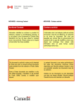
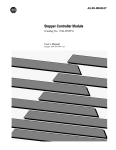
1.4.1 PSR4/5 Power Supply Module
Refer to Figure 1.1 for a quick reference of the
PSR4/5 and drawings A-93409, A-93408 and A93092 for precise details.
The PSR4/5 Power Supply Module is divided into
four (4) main sections:
1.
The Unregulated Logic Bus, supplied by the
Control AC line input voltage (normally
single-phase 115 VAC), is described in
Section 4.2.
2.
The 310/140 Main DC Bus is supplied by
the main AC line input voltage (normally
three-phase 230 VAC or single-phase 115
VAC).
3.
The Soft-Start Feature (standard) resistor
limits the inrush current (to charge-up the
Main Bus Capacitors) to a specific amount
as listed in Appendix D.
4.
The Shunt Regulator (regeneration) section
includes circuitry which monitors the main
bus. During deceleration profiles, the motor
basically operates as a DC generator and
pumps energy back into the main bus
causing the bus to rise. The Shunt Regulator
The BDS4 brushless servo system consists of three
main components:
1-2
1.
PSR4/5 - Power Supply Module
2.
BDS4 - Amplifier Module
3.
B
- Brushless Motor
BDS4
CHAPTER 1 - SYSTEM DESCRIPTION
Figure 1.1. BDS4 and PSR4/5 (Low Current Models shown)
limits the voltage rise during the
deceleration periods.
•
12 and 20 AMP Models:
The shunt regulator (regeneration) resistor
load is fuse protected. If the shunt regulator
is held on for too long, the shunt regulator
power transistor fails, or the shunt regulator
load resistor becomes shorted, the fuse will
blow and cause the Fault Contact on the
PSR4/5 to open and the BLOWN REGEN
FUSE LED to become illuminated.
1-3
CHAPTER 1 - SYSTEM DESCRIPTION
BDS4
These signals are associated with the
motor system resolver. A 7.0 kHz
excitation signal is generated in the
BDS4 and sent to the resolver. Two
resolver feedback signals (sine and
cosine) are received by the BDS4 and
processed by an R/D (resolver-todigital) converter. The R/D unit
generates a digital position word used in
electronically commutating the motor
and an analog velocity (internal tach)
signal to close the servo loop.
The shunt regulator also includes a duty
cycle limit circuit to protect against
excessive load resistor heating. If the
average duty cycle limit is exceeded, the
regeneration circuitry will become disabled,
the Fault Contact will open, and the
OVERLOAD LED will become illuminated.
To reset this fault, remove and reapply all
input line power; bus capacitors must
completely discharge.
•
50 and 75 AMP Models:
WARNING
The shunt regulator (regeneration) resistor is
protected by a thermal overload relay. If the
resistor rating is exceeded or if the shunt
regulator transistor fails, the thermal
overload output contacts will open
indicating an IMMEDIATE need to remove
the main power.
1.4.2 BDS4 Servo Amplifier Module
Refer to Figure 1.1 for a quick reference of the
BDS4's features.
The BDS4 Servo Amplifier is divided into four (4)
main sections:
1.
2.
Fault Diagnostics monitor various signal
leads. When a fault condition occurs the
fault circuit will become latched, the BDS4
will become internally inhibited, the
appropriate red LED will become
illuminated, and the Drive-Up contact will
open indicating that the BDS4 is in its
Inhibit mode.
The Input/Output interface circuitry is
divided into two functions:
(A) Signals to and from the motor and
BDS4.
1-4
(B) Signals to and from the signal
source (PLC, CNC, etc.) and BDS4.
The thermal overload output
contacts must be connected
into a shut down circuit (E
Stop string, etc.) to drop the
main power or a possible fire
hazard will exist. Refer to
Drawing A-93231.
There are numerous signals that may
interface between the signal source
(PLC, CNC, etc.) and the BDS4. These
inputs and modes of operation differ
with each application.
3.
The BDS4 consists of a single velocity loop
and three inner current loops. To give
precise velocity control, the velocity loop is
normally configured as a proportional, plus
an integral, plus a derivative gain servo loop.
The output of the velocity loop is the current
command for the three microprocessorbased current loops.
The heart of the BDS4 is its microprocessor
which receives and processes the current
command (velocity error) signal from the
output of the velocity loop circuit, the
position information from the resolver-todigital converter, and several other signals.
After receiving the velocity error, the
microprocessor generates three sinusoidal
current commands. These current
commands are forwarded to the three
proportional plus integral current loops, one
for each of the three motor phases.
The microprocessor is the key element in the
Industrial Drives patented torque angle
technique. The microprocessor varies the
phase of the currents with respect to motor
BDS4
CHAPTER 1 - SYSTEM DESCRIPTION
flux and significantly improves the motor
speed-vs-torque profile.1
4.
The outputs from the three current loop
circuits are converted into a 10 kHz pulse
width modulation scheme. The modulation
is such that the 10 kHz PWM results in 20
kHz current ripple in the motor, resulting in
very quiet motor operation.
1.4.5 With Soft-Start Circuit
(Standard)
1.
The PWM switching signals are optically
coupled to the power stage gate drive
hardware for complete electrical isolation.
The BDS4 uses IGBT's (Isolated Gate
Bipolar Transistors) for the output power
stage; allowing high frequency operation.
Only the Control AC line input voltage is
applied.
a.
The logic bus comes up.
b.
A power-up reset pulse is generated in
the BDS4.
c.
If no faults (other than main bus
undervolts) are present after the powerup reset pulse is generated (a delay of
one second) then the drive is ready to be
enabled. However, there can be no
motor movement until the main AC line
input voltage is applied.
1.4.3 Brushless DC Motor
2.
The Industrial Drives' B Series brushless motors
feature the latest in permanent magnet technology,
utilizing high energy Neodymium-Iron-Boron alloys.
These brushless motors consist of permanent magnet
rotors and three-phase Y-stator windings. This places
the heat producing member on the outside where it
can best dissipate heat. These motors (depending on
size) are either four- or six-pole motors. Since they
are brushless motors, there are no commutators or
associated brushes. The motors run as synchronous
motors, meaning the rotor speed is the same as the
speed (frequency) of the stator's rotating magnetic
field. The feedback device is a brushless resolver,
mounted internally as part of the overall motor
construction. Another available option is the integral
brush tachometer. For more information, refer to the
Installation and Service Manual, B Series Brushless
Motors M-89031.
1.4.4 Power Up/Down Sequencing
First, apply the 115 VAC control voltage. Second,
apply the main AC voltage. Third, check for faults
and then enable the BDS4. The AC line input
voltages may be removed in any sequence.
1 The BDS4A/V sine-wave controller allows a wider range speed
because it has the ability to electronically change the angle
between the rotor flux and the stator flux—commonly referred to
as torque angle. Industrial Drives, A Kollmorgen Division,
Patented Numbers 4,447,771; 4,479,078; and 4,490,661.
3.
The Main AC line input voltage is applied.
a.
The soft-start circuit charges the Main
DC bus capacitors in the PSR4/5
through a current limiting resistor.
b.
The shunt regulator regeneration
circuitry is switched from dynamic bus
discharge to regular mode.
c.
The undervoltage fault in the BDS4 is
now cleared (after approximately 3/4
sec. delay), and if jumper J21 is
installed on the BDS4-COMP Board,
the Drive Ready LED will become
illuminated and the Drive-Up contact in
the BDS4 (between Pins 10 and 20 of
Connector C1) will close. The BDS4 is
ready to be enabled and will enable
once the enable input is activated.
Only the Main AC line input voltage is
removed.
a.
Approximately 30 msec. after the Main
AC line input voltage is removed, the
shunt regulator is switched from
regulate to the dynamic bus discharge
mode, and the main DC bus power is
discharged.
b.
The shunt regulator circuit is
deactivated.
1-5
CHAPTER 1 - SYSTEM DESCRIPTION
c.
4.
BDS4
b. The shunt regulator regeneration
circuitry is switched from dynamic bus
discharge to regular mode.
The Drive-Up contact within the BDS4
will open due to Bus undervolts.
Only the Control AC line input voltage is
removed.
a.
The Drive-Up contact in the BDS4 will
open. The BDS4 is immediately
disabled.
b.
Operation of the soft-start/dynamic bus
discharge and other circuits within the
PSR4/5 will not be affected.
c.
The PSR4/5 fault contact will open.
c.
3.
Only the Main AC line input voltage is removed.
1.4.6 Without Soft-Start Circuit or
Dynamic Bus Discharge (Optional)
1.
2.
1-6
Only the Control AC line input voltage is
applied.
a.
The logic bus comes up.
b.
A power-up reset pulse is generated in
the BDS4.
c.
If no faults (other than main bus
undervolts) are present after the powerup reset pulse is generated (a delay of
one second) then the drive is ready to be
enabled. However, there can be no
motor movement until the main AC line
input voltage is applied.
The undervoltage fault in the BDS4 is
now cleared (after approximately 3/4
sec. delay), and if jumper J21 is
installed on the BDS4-COMP Board,
the Drive Ready LED will become
illuminated and the Drive-Up contact in
the BDS4 (between Pins 10 and 20 of
Connector C1) will close. The BDS4 is
ready to be enabled and will enable
once the enable input is activated.
4.
a.
The DC bus will bleed down slowly
after approximately five minutes.
b.
The shunt regulator is deactivated.
c.
The Drive-Up contact within the BDS4
will open.
Only the Control AC line input voltage is
removed.
a.
The BDS4 will be immediately
disabled.
b.
The BDS4 Drive-Up contact will open.
c.
The PSR4/5 fault contact will open.
The Main AC line input voltage is applied.
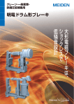
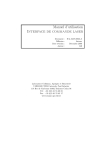
1.5 TYPICAL SYSTEM DIAGRAM
a.
Figure 1.2 illustrates a typical system with all of the
major components.
The soft-start circuit charges the Main
DC bus capacitors in the PSR4/5
through a current limiting resistor.
BDS4
1-7
CHAPTER 1 - SYSTEM DESCRIPTION
Figure 1.2. Typical System Diagram
BDS4
CHAPTER 2 - INSTALLATION
CHAPTER 2
INSTALLATION
2.1 INTRODUCTION
The information in this chapter will familiarize you
with the safety information, unpacking and
inspection, installation requirements, assembly
procedures and electrical connections for installing
the BDS4. A checklist is provided at the end of this
chapter to insure proper installation.
to the potential for personal injury. Follow the
recommended precautions and safe operating
practices included with the alert symbols.
"Warning" refers to personal safety. They alert you
to potential danger or harm. Failure to follow
warning notices could result in personal injury or
death.
2.2 SAFETY INFORMATION
"Caution" directs attention to general precautions,
which if not followed, could result in personal injury
and/or equipment damage.
The purpose of this section is to alert you to possible
safety hazards associated with this equipment and the
precautions you can take to reduce the risk of
personal injury and damage to the equipment.
"Note" highlights information critical to your
understanding or use of these products.
Safety notices in this manual provide important
information. Read and be familiar with these
instructions before attempting installation, operation,
or maintenance. Failure to observe these precautions
could result in serious bodily injury, damage to the
equipment, or operational difficulty.
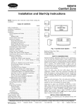
The safety-alert symbols are illustrated in Figure 2.1.
When you see these symbols in this manual, be alert
WARNING
CAUTION
NOTE
2.3 CONVENTIONS
To assist you in understanding the material in this
manual, conventions have been established to
enhance reader comprehension. Explanations of
these conventions are as follows:
•
Safety warnings, cautions, and notes present
material that is important to user safety. Be sure
to read any safety notices you see as they could
prevent equipment damage, personal injury, or
even death to you or a co-worker.
•
Bold text highlights other important information
that is critical to system operations.
Figure 2.1. Safety-Alert Symbols
2-1
CHAPTER 2 - INSTALLATION
•
CAPITALIZED text stresses attention to the
details of the procedure.
•
Underlined text emphasizes crucial words in
sentences that could be misunderstood if the
word is not recognized.
2.3.1 BDS4 vs. BDS4V vs. BDS4A &
PSR4/5 vs. PSR4/5A
The BDS4, BDS4V and the BDS4A differ in
according to the following:
BDS4
Original Standard Configuration
BDS4V
Industrial Standard Configuration
BDS4A
U.L. 508 Approved Configuration
BDS4
2.3.3 Abbreviations
CCW
CW
DIFF CMD
D/L
GC
GCS
LED
NEC
P/N
R/D
Regen
TL
UL
Counter Clockwise
Clockwise
Differential Command
Direction Limit
Goldline Cable
Goldline Cable Set
Light Emitting Diode
National Electrical Code
Part Number
Resolver-to-Digital
Regeneration
Test Limits
Underwriters Laboratories
2.4 UNPACKING AND INSPECTION
The BDS4 is the original amplifier developed by
Industrial Drives. It was followed by a value analysis
version, the BDS4V. The BDS4A was later
developed and submitted to UL for approval.
CAUTION
Electronic components in
this amplifier are static
sensitive. Use proper
procedures when handling
component boards.
In a similar manner, the PSR4/5 and PSR4/5A follow
this scheme:
PSR4/5
Original Standard Configuration
PSR4/5A
UL 508 Approved Configuration
Upon receipt of the equipment, closely inspect
components to ensure that no damage has occurred in
shipment. If damage is detected, notify the carrier
immediately.
This indicates that the BDS4A and PSR4/5A meet all
the safety standards set by the Underwriter
Laboratories. Where differences occur between
models, special instructions will be indicated in this
manual. For the purpose of referencing all amplifiers
and power supplies, the nomenclatures BDS4 and
PSR4/5 will be used. Check your model number to
verify your model.
Carefully remove packing material and remove the
equipment from the shipping container. Do not
dispose of shipping materials until the packing list has
been checked. Parts that are contained within the
shipment, but not physically attached to the
equipment, should be verified against the packing list.
If any parts are missing, notify Industrial Drives at
once.
2.3.2 Model Numbering Scheme
2.5 INSTALLATION REQUIREMENTS
All Industrial Drives components contain a model and
serial number printed on a black and gold tag on the
front panel. The model number identifies how the
equipment is configured. Refer to Appendix C for
the model number scheme tables. These tables
explain what the model configurations are. You
should verify that the model numbers represent the
equipment desired for your application. Also verify
the compatibily between components of the servo
system.
Proper installation and field wiring are of prime
importance when considering the application of servo
amplifiers. Many problems may be avoided if
installation of the equipment is done properly. Users
should familiarize themselves with and follow
installation and wiring instruction in addition to all
applicable codes, laws and standards. Pay special
attention to the following topics when installing
Industrial Drives' equipment.
2-2
BDS4
CHAPTER 2 - INSTALLATION
2.5.1 Environmental Considerations
The environment that this equipment is placed in can
have dramatic effects on its operation. Industrial
Drives recommends that the BDS4 and PSR4/5 be
operated and stored under the following conditions:
Depending on the continuous current ratings of the
BDS4 and PSR4/5 modules, a total of six (6)
amplifiers may be mounted with a single power
supply. However, the maximum number of BDS4
amplifiers mounted on either side of the PSR4/5
power supply module must not exceed four (4).
•
Operating Temperature: 0° C to 45° C
Mounting combinations for the PSR4/5 and BDS4
modules are as follows:
•
Storage Temperature: -20° C to 70° C
•
•
Humidity: 10% to 90% (Non Condensing)
PSR4/5-X12; a maximum of four (4) BDS4
amplifiers sequentially or "split mounted"
(amplifiers are mounted on both sides of the
PSR4/5) at either side of the PSR4/5 in
descending order of continuous current ratings.
•
PSR4/5-X20; a maximum of four (4) BDS4
amplifiers sequentially or "split mounted" at
either side of the PSR4/5 in descending order of
continuous current ratings.
•
PSR4/5-X50; a maximum of six (6) BDS4
amplifiers ("split mounted" only) to either side,
not to exceed four (4) amplifiers on a side,
mounted in descending order of continuous
current ratings.
•
PSR4/5-X75; a maximum of six (6) BDS4
amplifiers ("split mounted" only) to either side,
not to exceed four (4) amplifiers on a side,
mounted in descending order of continuous
current ratings.
2.5.2 Enclosures
It is suggested that the BDS4 and PSR4/5 be mounted
in a cabinet or other suitable enclosure to protect
them from physical and environmental damage.
Refer to Appendix D for complete system
dimensions.
CAUTION
Allow sufficient clearance for
the large "regenerative" heat
producing resistor(s)
mounted at the upper edge
of the PSR4/5 unit and the
externally mounted regen
(shunt regulator) power
resistor(s).
2.6 ASSEMBLY
The BDS4 and PSR4/5 are both constructed prior to
shipping from the factory. The only assembly
required is the mounting of the devices.
NOTE
2.6.1 Mounting
Refer to the drawing of your model system in
Appendix F for outline and dimensions. Be sure to
look at the proper drawing for mounting
measurements.
The PSR4/5 and BDS4 modules should be mounted
in the vertical position. To minimize cross talk and
enhance air flow, maintain a minimum of 20
millimeters (0.75 in.) on either side of each unit and
at least 40 millimeters (1.5 in.) of unobstructed space
above and below the units.
CAUTION
Refer to The drawing of your
model system in Appendix F
for the Mounting Hole Pattern
information.
Allow sufficient clearance for
the large "regenerative" heat
producing resistor(s). The
internal resistors are
mounted at the upper edge of
the PSR4/5 unit. The
externally mounted regen
(shunt regulator) power
resistor(s) are mounted
above the PRS4/5A unit.
2-3
CHAPTER 2 - INSTALLATION
2.6.2 Mounting the External
Regeneration Resistor(s)
BDS4
To facilitate wiring, the BDS4 amplifiers must be
mounted next to the PSR4/5 power supply module in
descending order according to their continuous
current ratings. Refer to Section 2.6.
External regenerative
resistors are a shock hazard!
WARNING
Mount these resistors
properly! Enclose these
resistors to protect personnel
and equipment!
External regeneration
resistors can become
extremely hot!
CAUTION
Allow safe clearance around
the resistor(s) enclosures.
Proper ventilation must be
provided.
Some models of PSR4/5 use an externally mounted
regen (shunt regulator) resistor. The resistor kit
includes mounting hardware and, depending on the
model, a thermal overload relay to be wired in with
the resistors. A suitable enclosed location outside the
equipment cabinet needs to be set aside for mounting
these components while observing the heat and shock
requirements of these resistors.
2.7 ELECTRICAL CONNECTIONS
WARNING
2-4
Dangerous voltages,
currents, temperatures, and
energy levels exist in this
product and in the
associated servo motor(s).
Extreme caution should be
exercised in the application
of this equipment. Only
qualified individuals should
attempt to install, set-up,
and operate this equipment.
Ensure that he motor, drive,
and the end-user assembly
are properly grounded per
NEC requirements.
NOTE
In order to adhere to suitable
engineering practice, the AC
control voltage (115 VAC for
the logic bus) must be
applied first to activate the
control and fault logic
circuits prior to applying the
main AC voltage.
Follow these precautions:
1.
Observe all notes on the wiring diagram.
2.
All motor stator leads, signal input leads,
resolver leads, encoder leads, and tachometer
leads must be shielded.
3.
Twist all AC leads to minimize electromagnetic
emissions (noise).
4.
Avoid running signal leads (must be shielded)
in close proximity to power leads, motor stator
leads, or other sources of electromagnetic
noise.
5.
Minimize lead lengths as much as possible.
6.
Connect the BDS4 system according to the
System Wiring Diagram; pay close attention to
the grounding scheme.
7.
Provide adequate stress relief for cables.
The notes on BDS4 Wiring
Diagram (A-93231) give
specific wiring details.
NOTE
Thermal overload protection for the motor is not
provided within the PSR4/5 or the BDS4 and must be
provided externally. Refer to the National Electrical
Code for proper sizing of overload protection.
With the exception of the hook-up of the motor, the
main input voltage, and the main Bus+ and Bus- DC
voltage, all interface wiring between the BDS4,
BDS4
CHAPTER 2 - INSTALLATION
Table 2.1. Torque Values
CONNECTING
POINTS
BDS4-3-20
AMP UNITS
BDS4-30-55
AMP UNITS
PSR4/5-12-20
AMP UNITS
PSR4/5-50-75
AMP UNITS
AC Input Screws
12 in. lb.
20 in. lb.
12 in. lb.
20 in. lb.
DC Bus Screws
12 in. lb.
20 in. lb.
12 in. lb.
20 in. lb.
Motor Connecting
Screws
12 in. lb.
20 in. lb.
12 in. lb.
20 in. lb.
12 in. lb.
20 in. lb.
External Regen
Screws
Ground Screws
12 in. lb.
20 in. lb.
PSR4/5, and other equipment is accomplished by
connectors supplied with the BDS4 and PSR4/5 units.
The input/output connections are grouped by
connector or terminal block. They are input/output,
motor, resolver, AC main power and control voltages,
main DC bus, and unregulated DC voltages.
To connect the power bus of the PSR4/5 to the BDS4
amplifiers the following is suggested:
•
For PSR4/5-X12 modules, use 600 VAC
insulated 14 AWG or larger wire.
•
For PSR4/5-X20 modules, use 600 VAC
insulated 10 AWG wire.
•
For PSR4/5-50 and PSR4/5-75 modules, use
600 VAC insulated 8 AWG or larger wire.
Captive screws are used in the power terminals of the
PSR4/5-X12 module, PSR4/5-X20 module, and the 3
amp thru the 20 amp BDS4 amplifiers. Do not
attempt to remove these screws to use ring terminals.
Use locking spring terminals similar to Hollingsworth
#XSS20945S or #SS20947SF for 16 and 14 AWG
wire and #XSS20836 or #SS20832F for 12 and 10
AWG wire.
2.7.1 Recommended Torque for
Electrical Connections
Table 2.1 displays the recommended torque values
for terminal block and grounding connecting points.
All torques are measured with the wire or terminal lug
underneath the screw head.
2.7.2 Grounding Scheme
To prevent shock hazard to personnel and to ensure
proper operation of the servo system, the BDS4,
PSR4/5, and the servo motor must be grounded
according to NEC specifications. Each BDS4 and
PSR4/5 have at least two grounding screws on the
front of the chassis.
NOTE
Provisions of the National
Electrical Code with respect
to grounding should be
followed. These precautions
generally deal with the
ground loop currents arising
from multiple ground paths.
Only one ground path should
be used.
One of the screws on the chassis of the PSR4/5
should go to earth or machine ground. The other
should be connected to the adjacent BDS4 ground
screw along with the ground wire from the motor.
The free ground screw on the BDS4 chassis should
then be connected to the next BDS4, etc.
For grounding to machine or earth ground, a screw
lug should be attached to the ground screw or stud on
the PSR4/5 or BDS4. A torque of 12 in.lb. for
ground screws and 20 in.lb. for ground studs is
recommended. Also refer to the National Electrical
Code (NEC) or UL standard 486B for recommended
torque's.
2-5
CHAPTER 2 - INSTALLATION
BDS4
2.7.3 Connecting the AC Input
Voltages
2.7.5 Connecting the Unregulated DC
Voltage to the BDS4 (Connector C3)
The Main AC Input Voltage, either single- or threephase, should be connected at La, Lb, and Lc on the
power terminal block located on the front of the
PSR4/5 unit. The PSR4/5 is not line-phase sensitive.
When using the 12 or 20 amp PSR4/5 with singlephase main power, the input lines may be connected
to any two (2) terminals La, Lb, or Lc.
The wiring between the BDS4 Connector C3 and the
PSR4/5 Connector C2 (unregulated voltage) is in
Table 2.2 and the pinouts are in Figure 2.3.
The Control AC input voltage should be wired to
Connector C1 - Pins 2 and 3 on the PSR4/5 and from
Connector C1 - Pins 5 and 6 of the PSR4/5 to
Connector C4 - Pins 1 and 2 (fan units only) on the
BDS4.
NOTE
Connector C4 is present only
on BDS4 Amplifiers that have
continuous ratings of 20 amps
and above.
2.7.4 Connecting the PSR4/5 Fault
Output Contact (Connector C1)
Pins 1,4 Fault Contact
The Fault Output Contact closes when power is
applied to the PSR4/5. This contact opens on a fault
condition within the PSR4/5 only.
The pinouts for C1 are listed in Figure 2.2. Refer to
Note 2 of the BDS4 Wiring Diagram (A-93231) for
further information concerning the PSR4/5 Fault
Output Contact.
2-6
2.7.6 Connecting the Main DC Bus
Voltage
Refer to notes 4 and 6 on BDS4 Wiring Diagram A93231 for details concerning the hook-up of the Bus
+ and Bus - circuits between the PSR4/5 and the
BDS4 amplifiers.
Failure to observe correct
polarity will result in damage
to the PSR4/5 and BDS4.
WARNING
2.7.7 Connecting the External
Regeneration Resistor(s)
If an external regeneration resistor is specified,
connecting points are provided on the PSR4/5 Power
Supply Unit (refer to Notes 3 and 10 on BDS4
Wiring Diagram A-93231).
BDS4
CHAPTER 2 - INSTALLATION
Table 2.2. BDS4 Unregulated DC Voltages (C3)
VOLTAGE
CURRENT
BDS4
CONNECTOR C3
PINS
PSR4/5
CONNECTOR C2
PINS
+18 V Nominal
(+17 V to +26.5 V)
NO LOAD
1, 5
1, 5
-18 V Nominal
(-17 V to -26.5 V)
NO LOAD
2, 6
2, 6
COMMON
---
3, 7
3, 7
10 V Nominal
(+9 V to +14 V)
NO LOAD
4, 8
4, 8
+ 14.5 V MIN.
1 AMP ON PSR4/5
12 OR 20 AMP
UNITS
1, 5
1, 5
2, 6
2, 6
2 AMP ON PSR4/5
50 OR 75 AMP
UNITS
- 14.5 V MIN.
1 AMP ON PSR4/5
12 OR 20 AMP
UNITS
2 AMP ON PSR4/5
50 OR 75 AMP
UNITS
COMMON
---
3, 7
3, 7
+ 6.5 V MIN.
2 AMP ON PSR4/5
12 OR 20 AMP
UNITS
4, 8
4, 8
4 AMP ON PSR4/5
50 OR 75 AMP
UNITS
FAULT
CONTACT
4
1
FAULT CONTACT
115 V OUTPUT
5
2
115 V INPUT
115 V OUTPUT
6
3
115 V INPUT
Figure 2.2. PSR4/5 (C1)
+18 VDC
5
1
+18 VDC
-18 VDC
6
2
-18 VDC
COMMON
7
3
COMMON
+10 VDC
8
4
+10VDC
Figure 2.3. BDS4 (C3) & PSR4/5 (C2)
(Nominal, No Load Voltages)
2-7
CHAPTER 2 - INSTALLATION
BDS4
DIFF HI
11
1
DIFF LO
AUX IN
12
2
________
ENABLE
_______
I LIMIT
13
3
_____
RESET
______________
TORQUE HOLD
14
4
DIFF SHIELD
COMMON
15
5
SHIELD
COMMON
16
6
SHIELD
COMMON
17
7
_______________
OUTPUT FAULT
I MONITOR
18
8
___________
FOLD BACK
SPEED MONITOR
19
9
__________
OVERTEMP
DRIVE-UP
20
10
DRIVE-UP
Figure 2.4. BDS4 Connetor (C1)
2.7.8 Connecting the BDS4
Input/Output (Connector C1)
The following descriptions tell the user which inputs
and modes of operation are available, enable the user
to identify the appropriate connecting points on
Connector C1, and help the user decide which inputs
and modes of operation to use. The pinouts are listed
in Figure 2.4.
Pins 15,16,17
Common
These pins provide commons (returns) between
external equipment (numerical controls, etc.) and the
BDS4.
Pins 4,5,6
2-8
Shield
These pins provide termination points for cable
shields. To insure there are no ground loops in the
shield common, connect only one end, butt and
insulate the other end.
Pin 11
DIFF CMD HI
Pin 1
DIFF CMD LO
Differential velocity or current command input +10
V full scale, 20 K Ohm input impedance. Should be
shielded.
_____
Pin 2
Enable
Allows the BDS4 to be enabled or disabled without
removing the main power. When a circuit is closed
between Pin 2 and common, the BDS4 will be put
into the Drive-Up mode. Opening the circuit puts
the BDS4 into the Inhibit mode [internal 20 K Ohm
pull-up resistor to +12 VDC] (Green LED
indicated).
_____
Pin 3
Reset
Allows any latched fault circuit except
OVERVOLTS or OVERCURRENT faults to be
reset by toggling Pin 3 to common. It has a 20 K
Ohm pull-up resistor to +12 VDC.
__________
Pin 7
Output Fault
Open collector signal (logic low) to indicate that
either an overcurrent or overvoltage fault has
occurred in the Power Stage of the amplifier. 25 ma
sink capabilities, 30 VDC Max (red LED indicated).
_______
Pin 8
Foldback
Open collector signal (logic low) to indicate that the
amplifier has started to reduce peak current due to
excessive loading, 25 ma sink capabilities, 30 VDC
max (red LED indicated).
________
Pin 9
Overtemp
This output will transition low to indicate the BDS4
amplifier is being subjected to an excessive
temperature condition. Open collector, logic low, 25
ma sink capability, 30 VDC max (red LED
indicated).
_______
Pins 10,20
Drive-Up
BDS4
CHAPTER 2 - INSTALLATION
The Drive-Up contact closure (internally) indicates to
the outside world that the BDS4 amplifier is in the
Drive-Up mode; or when the contact is open, it
indicates the Inhibit mode. The contact is rated at
115 VAC at 2 amps (green LED indicates Drive
Ready).
The Drive-Up relay acts in conjunction with the
Enable circuit in one of two possible modes of
operation as determined by optional jumper J21. To
determine which mode of operation is being utilized,
refer to J21 on the TEST LIMITS SHEET.
1.
Drive-Up Mode
J21 is not installed on the BDS4-COMP Board.
Apply power.
mode applications or used as the tach input for
integrally motor-mounted tachometer generators.
Pin 13
The Current Limit input allows access to the Current
Limit circuitry providing a means by which inputs
may be applied for adaptive control applications.
This single ended input may also be used to adjust the
peak current limit of the amplifier from 7.5% to
100% of its rating. A positive voltage from 0 VDC to
7.5 VDC corresponds to 7.5% to 100% respectively.
Also, a resistor to common may be used to program
the current limit with 75% of I peak = 8.6 K Ohm,
50% of I peak = 3.3 K Ohm. The Current Limit
Adjustment Pot may also be used to adjust the peak
torque of the motor to the desired level.
When the Enable input circuit is activated (pulled
low), the internal Drive-Up contact will close and the
green Drive Ready LED will become illuminated.
However, when the Enable input circuit is not
activated, or a fault occurs, the internal Drive-Up
contact will be open and the green Drive Ready LED
will be off indicating that the BDS4 is in the Inhibit
Mode.
Pin 14
If a fault occurs within the BDS4, the Drive Ready
LED will turn off and the Drive-Up contact will open
and remain open regardless of the state of the Enable
input circuit.
Pin 18
2.
O.K. to Enable/Drive-Up Mode
JR21 is installed on the BDS4-COMP Board
(Standard).
Apply power.
When there are no faults present, the internal DriveUp contact will be closed and the green Drive Ready
LED will be illuminated indicating that the BDS4 is
OK-TO-ENABLE. However if there is a fault
present, the Drive-Up contact will be open and the
Drive Ready LED off indicating that the BDS4 is in a
fault mode. In this case, activating the Enable input
circuit will not enable the BDS4.
Pin 12
Aux IN
This is an additional single ended input to the
velocity loop. This input may be used in adaptive
I Limit
Torque Hold
The BDS4 may be converted from a constant velocity
amplifier to a constant torque amplifier (at stall only)
by closing a circuit between Pin 14 and common (via
internal 20 K Ohm pull-up resistor). The velocity
loop operational amplifier is maintained at unity gain
while in this mode of operation.
I Monitor
There is a direct relationship between the signal
appearing at this output and actual motor current. A
DC voltmeter placed between Pin 18 and common,
calibrated in either current or torque, can be used to
estimate the constant load levels placed on the motor.
The current scale factor at Pin 18 is 8V = Peak RMS
current rating of the BDS4 (3 K Ohm output
impedance). This output is for reference only. Its
accuracy decreases as current decreases: +/- 4% at
peak current, +/-9% at continuous current, +/- 12% at
1/2 continuous current.
Pin 19
Speed Monitor
There is a direct relationship between the signal
appearing at this output and actual motor speed. A
DC voltmeter (or other instrument) placed between
Pin 19 and common, calibrated in RPM, can serve as
a means by which speeds may be monitored. Refer to
the TL Sheet for the scale factor in volts/RPM (8
volts = maximum speed) as listed on the TL Sheet for
the particular motor/amplifier combination (3K Ohm
output impedance).
2-9
CHAPTER 2 - INSTALLATION
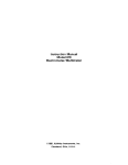
2.7.9 Connecting the Motor
B SERIES MOTORS have a
thermostat switch wired to the
resolver connector at the
motor.
BR SERIES MOTORS have a
thermostat switch wired to the
stator connector at the motor.
NOTE
CAUTION
WARNING
The motor thermostat switch
is an automatic resetting
device and should be
connected directly into a
latched (locked out) power
down type circuit.
Incorrect motor resolver
phasing can cause erratic
operation, runaway, or
damage to the system.
BDS4
shielded pairs for the resolver.
The leads of the three-phase synchronous motor are
brought out to Pins A, B, and C of the motor
connector. Pin D is ground for the motor. Refer to
Figure 2.7 for pin connections.
Terminate Pins A, B, and C of the motor connector to
Ma, Mb, and Mc, respectively, on the power terminal
block located on the front of the BDS4 amplifier.
Terminate Pin D at the BDS4 chassis ground screw.
Refer to Wiring Diagram (A-93231) and the
appropriate motor HD (hook-up) drawing.
The optional integrally-mounted tachometer is
brought out to Pins R and S on the resolver connector
for both the B and BR series motors. Pin R (Tach Hi)
should be terminated at Connector C1 - Pin 12 (Aux
In) of the BDS4. Pin S (Tach Lo) should be
terminated at Connector C1 - Pin 15 (common) of the
BDS4. The tachometer is an option and is not
installed on most motors.
2.8 INSTALLATION CHECKLIST
Refer to BDS4 Wiring Diagram (A-93231).
Terminate Pins A, B, C, D, E, and F of the resolver
connector at Connector C2 on the BDS4 as shown by
Figures 2.5 and 2.6. Also see the BDS4 Wiring
Diagram (A-93231) and the appropriate motor HD
(hook-up) drawing or Motor Connection Diagram (A63542). Use cables with three (3) independently
SIN HI
7
1
SIN LO
SIN SHIELD
8
2
COS SHIELD
COD HI
9
3
COS LO
REF LO
10
4
REF HI
SPARE SHIELD
11
5
REF SHIELD
N/C
12
6
N/C
Figure 2.5. BDS4 (C2)
2-10
Before applying power to the PSR4/5 and BDS4,
check the following items to ensure proper operation:
CAUTION
To prevent damage to the
equipment, the motor and
resolver, the AC line voltage,
and the DC bus voltages must
be connected as indicated by
BDS4 Wiring Diagram (A93231).
BDS4
CHAPTER 2 - INSTALLATION
2.8.1 Checking the Motor and
Resolver Wiring
Disconnect both the motor stator and resolver
connectors from the motor. Using an ohmmeter,
check the continuity of each motor stator lead
between the motor stator connector pin and the
BDS4. Using an ohmmeter, check the continuity of
each motor resolver lead between the motor resolver
connector pin and the BDS4. The motor stator and
resolver leads should be connected according to
BDS4 Wiring Diagram (A-93231). There are no
other options for connecting the motor stator and
resolver leads.
2.8.2 Checking the AC Line Voltages
Open the circuit breaker or remove the fuses in the
Main AC lines that are connected to the PSR4/5 at La,
Lb, and Lc. Remove Connector C1 from the PSR4/5,
and remove (if present) Connector C4 from the
BDS4.
Apply only the AC main power. Use an AC
voltmeter to check and record the 1- or 3-phase lineto-line voltage at the circuit breaker or fuse holders.
Remove power. Note the model number of the
PSR4/5 and refer to Appendix B to confirm the
correct Main AC voltage level.
Figure 2.6. Motor Resolver Connections
2-11
CHAPTER 2 - INSTALLATION
BDS4
Figure 2.7. Armature Motor Connections
Apply only the AC control power. Use an AC
voltmeter to check and record the single-phase
voltage at Connector C1 of the PSR4/5. Remove
power. Note the model number of the PSR4/5 and
refer to Appendix B to confirm correct Control AC
voltage level.
If the voltage levels are within the specifications
listed in Appendix B, proceed with the Check-Out
procedure.
Close the circuit breaker or re-install the fuses for the
Main AC input power. Re-install Connectors C1 and
C4 (if present).
WARNING
Remove power.
Remove the Bus+ and Bus- leads from the PSR4/5
power terminal block. Remove mating Connector C2
from the PSR4/5.
Apply power.
2.8.3 Checking the DC Bus Voltages
2-12
Allow sufficient time (after
removing power from the
system) for the voltage to
bleed down before connecting
or disconnecting wires at the
bus.
BDS4
Check and record the Main DC Bus Voltage output at
(+) with respect to (-) on the PSR4/5 terminal block
according to Section 2.1. Check and record the
unregulated DC voltage levels at Connector C3 of the
PSR4/5. They should be ± 17 to 26.5 and + 9 to 14.5
VDC per Section 2.7.5.
CHAPTER 2 - INSTALLATION
WAIT FOR THE BUS TO BLEED DOWN and
reconnect the B(+) and B(-) leads to the power
terminal block of the PSR4/5. Be careful to
reconnect the leads with the proper polarity. Reinstall Connector C2 on the PSR4/5.
Failure to observe correct
polarity will result in damage
to the PSR4/5 and BDS4.
Remove power.
Note the model number of the PSR4/5 and refer to
Section 2.1 to confirm DC voltage levels.
CAUTION
If the voltage levels are within the specifications
listed in Appendix D, proceed.
2-13
BDS4
CHAPTER 3 - OPERATION
CHAPTER 3
OPERATION
3.1 INTRODUCTION
The information in this chapter will enable you to
become familiar with system components and their
dependence upon one another. Also, it will help you
ensure each component is configured and functions
properly. At this point, all safety stops and other
precautions should be in place and working properly.
Be prepared to stop the machine if necessary.
CAUTION
Unloaded motors,
compensated for a large
inertia mismatch, may
become unstable when the
system is activated. Refer to
the test limits (TL) sheet for
stable load inertia range. If
the system becomes
unstable, remove the power
immediately.
3.2 INITIAL START-UP
You should now be ready to supply power to test the
servo systems functions and features. Work with only
one axis section at a time. Confirm all other BDS4
amplifiers are inhibited, meaning the enable circuits
are open (high).
CAUTION
Incorrect servo-to-position
loop phasing can cause
excursion oscillations, or
runaways.
Appropriate precautions should be taken to stop the
machine if necessary. Limit switches and safety
devices should be in place.
3.3 SEQUENCE OF OPERATIONS
This section contains a basic start-up sequence that
should be followed the first time the servo system is
initialized. READ THIS ENTIRE SECTION
BEFORE PERFORMING ANY OF THESE
PROCEDURES. When you apply power to the
system, pay special attention to the LEDs on the
BDS4 front panel. The CONTROL VOLTS and
DRIVE READY (green) LEDs should be illuminated.
This indicates that the system is functioning properly.
Should a FAULT (red) LED remain on for more than
a instant, immediately disconnect power and consult
Chapter 5 - Troubleshooting.
1.
Apply power. Enable only one BDS4.
Observe the action of the machine. If the
direction of the motor shaft rotation is reversed
3-1
CHAPTER 3 - OPERATION
(motor shaft turns in the wrong direction),
remove power.
2.
Reverse the input to the BDS4 at DIFF CMD
HI and DIFF CMD LO at Connector C1, Pins 1
and 11. DO NOT ATTEMPT TO
REVERSE DIRECTION OF ROTATION
BY INTERCHANGING MOTOR LEADS
AND/OR RESOLVER LEADS.
NOTE
3-2
If the motor is commanded to
move and does not respond,
turn the command scale
adjustment several turns CW.
BDS4
If the servo system performed properly, then read
Chapter 4 - Maintenance for adjustments and other
information that may be helpful in adapting your
system to your own applications.
BDS4
CHAPTER 4 - MAINTENANCE
CHAPTER 4
MAINTENANCE
4.1 INTRODUCTION
The information in this chapter will enable you to
maintain the systems components ensuring smooth,
efficient operation of the motor. Adjustments to the
system are broken in three (3) categories: Set-Up,
Response and Application Dependent, and Design
Tolerance. These adjustments allow the user to tailor
the BDS4 to their specific applications.
4.2 PREVENTATIVE MAINTENANCE
CAUTION
CAUTION
4.2.1 Transient Voltages
All transient-producing
devices must be properly
suppressed.
NOTE
Solid state controls of the BDS4 may be affected by
transient voltages. These voltages are in excess of the
specified voltage for any given circuit. When these
peak voltages occur, even for less than a second,
permanent damage to the BDS4 can occur.
Preventative maintenance to
this equipment must be
performed by qualified
personnel familiar with the
construction, operation, and
hazards involved with the
application.
In order to help avoid transient voltages that may
interfere with electronic circuit functions within the
PSR4/5 and BDS4, all switched inductive devices or
their wiring (solenoids, relay coils, starter coils, etc.)
must be suppressed. A 220 ohm, 1/2 watt resistor in
series with a 0.5 micro farad, 600 volt capacitor or
equivalent is suggested.
Electronic components in this
amplifier are static sensitive.
Use proper procedures when
handling component boards.
4.2.2 Surge Current
Preventative maintenance should be performed with
the BDS4 system out of operation and disconnected
from all sources of power.
Excessive current greater than that of the specified
limits of the PSR4/5 and BDS4 can cause permanent
damage to the system. Current limiting means are
recommended to protect from these currents.
4-1
CHAPTER 4 - MAINTENANCE
CAUTION
If the short circuit inrush
current generated by the
power source is in excess of
5000 amps RMS symmetrical
current, an isolation
transformer or line inductor
must be utilized in the
incoming power circuit.
Failure to observe this
precaution could result in
damage to, or destruction of
the PSR4/5 and BDS4.
Input transformers step up or step down input voltage
and can be either autotransformers or isolation
transformers. Isolation transformers help eliminate
the following:
•
Damaging AC line voltage transients reaching
the PSR4/5 and BDS4.
•
Damaging currents which may develop if a
point inside the PSR4/5 or BDS4 becomes
grounded.
4.2.3 Electrical Noise
The low levels of energy in the BDS4 control circuits
may cause them to be vulnerable to electrical noise.
Sources of electrical noise are those pieces of
equipment that have large, fast changing voltages and
currents when they switch on and off. These devices
have the capability of inducing critical current and
voltage transients on their respective power lines.
These transients must be accommodated for with
noise immunity provisions.
Electrical noise is prevented with the same methods
as Surge Current and Transient Voltages. However,
there are other methods of preventing electrical noise.
Such as:
•
Maintain physical separation between electrical
noise sources and the BDS4 amplifier.
•
Maintain physical separation between electrical
noise sources and the BDS4 control wiring.
This can be accomplished by using separate
conduits or wiring trays for control wiring and
power wiring.
4-2
BDS4
•
Use twisted-pair wiring for control circuits of
the BDS4.
•
Follow good grounding practices when wiring
the PSR4/5 and BDS4. Be careful not to create
a grounding loop with multiple ground paths.
Follow the NEC's provisions on grounding.
4.2.4 Radio Frequency Energy
This equipment generates
radio frequency energy.
NOTE
This equipment uses, and can radiate radio frequency
energy and must be installed and used in accordance
with this installation and service manual in order to
prevent possible interference with radio
communications or other electronic equipment.
4.3 PERIODIC MAINTENANCE
Periodic maintenance must be performed by qualified
personnel familiar with the construction, operation,
and hazards involved with the BDS4 and its
application. Power should be disconnected during all
maintenance procedures.
4.3.1 Ventilation
The PSR4/5 and BDS4 should be mounted vertically
to allow maximum ventilation of the components.
This configuration allows the heat generated by the
components to vent through the top and draft in
cooler air through the bottom. The top and bottom of
the components are vented to allow this drafting to
occur. These ventilation passages should be kept
open. If the PSR4/5 requires auxiliary cooling with
fans, inspect the fans on a regular basis.
4.3.2 Grounding Integrity
The method employed for grounding or insulating the
equipment from ground should be checked to assure
its integrity on a regular basis. This check should be
performed with the power off and the testing
equipment grounded.
BDS4
CHAPTER 4 - MAINTENANCE
4.4 ADJUSTMENTS
Adjust pots with proper
adjustment tool.
NOTE
DO NOT FORCE.
The adjustments are classified into three categories:
1.
Set-Up Adjustments - Adjustments that are
necessary at installation (accessible at the front
of the BDS4).
Motor System Resolver Phasing and
Alignment - Should be checked the first time
(if I.D. cables are not used).
Balance Adjustment.
Command Scale Adjustment.
2.
Response and Application Dependent
Adjustments - These adjustments add
versatility to the BDS4 and allow it to be
"tailored" to specific applications (accessible at
the front of the BDS4).
4.4.1.1 Balance Adjustment (Within
Position Loop)
If a monitor or readout displays Following Error,
adjust Balance Pot for zero Following Error at zero
speed.
Optional: Monitor DIFF CMD HI with respect to
DIFF CMD LO with a DC voltmeter. Command zero
speed from the Numerical Controller. Adjust
Balance Pot for zero volts on the meter.
4.4.1.2 Balance Adjustment
(Automatic or Manually Operated
Machines)
Monitor DIFF CMD HI with respect to DIFF CMD
LO with a DC voltmeter. With the input signal at
zero volts or with the input shorted to common, adjust
Balance Pot for zero speed.
4.4.1.3 Command Scale Adjustment
(Within Position Loop)
If the following error is displayed by monitor or
readout, command a slow feed rate and adjust
Command Scale Pot for the proper amount of
Following Error at that speed.
Stability Adjustment.
Current Limit Adjustment.
3.
Design Tolerance Adjustments - Factory set
and sealed adjustments should never require
customer adjustment (internal adjustments).
Current Sensor Offset Adjustments - Pots AZ
and CZ.
Resolver Excitation Adjustment - Pot OSCG.
FACTORY ONLY ADJUSTMENTS - Pots
R/DTR, R/DG, and R/DZ.
4.4.1 Set-Up Adjustments
At equipment start-up, make these adjustments.
4.4.1.4 Command Scale Adjustment
(Automatic or Manually Operated
Machines)
Turn the Command Scale Pot fully CCW. Apply an
input signal level which equals maximum desired
motor speed in RPM. Adjust Command Scale Pot
CW for maximum desired motor speed. DO NOT
EXCEED THE MAXIMUM MOTOR SPEED
THAT IS LISTED ON THE TL SHEET FOR
THE SYSTEM.
Refer to the Test Limits Sheet (TL) to identify the
maximum scaling of input signal. Maximum + 10
volts is standard.
4.4.2 Response and Application
Dependent Adjustments
These adjustments allow versatility in altering the
dynamic response of the BDS4 system as needed.
4-3
CHAPTER 4 - MAINTENANCE
When altering the response of the system, it may be
necessary to adjust both the STABILITY and the
CURRENT LIMIT adjustments.
BDS4
4.4.3 Design Tolerance Adjustments
(Factory Set and Sealed)
4.4.2.1 Stability Adjustment
In many cases, the Stability Pot will not need to be
adjusted and may be left in its fully CCW position.
However, this pot can be used to improve the
dynamic response of the servo loop, by adjusting the
Dynamic (AC) Gain. To adjust the AC Gain to the
proper point, use an oscilloscope to monitor the
internal tach signal at the SPEED MONITOR test
point with respect to A-COM (refer to Figures 1 and
3). Use a second channel of the scope to monitor the
current signal at the I MONITOR test point, also with
respect to A-COM (refer to Figures 1 and 3). Turn
the STABILITY Pot fully CCW. Apply a step input
(rapid) command signal. While accelerating and
decelerating the motor at approximately 25% of
maximum speed, adjust the STABILITY Pot CW
and notice the tach and current wave forms at the
SPEED MONITOR and I MONITOR test points.
Watch for indications of instability (i.e., ringing) in
the wave forms while accelerating and decelerating
the motor. Turn the STABILITY Pot CCW until the
tendency to go unstable disappears.
4.4.2.2 Current Limit Adjustment
The maximum peak current limits are set at the
factory and can not be increased above the level listed
on the Test Limits sheet (TL). Although the peak
current limits cannot be increased above the specified
value, they may be decreased.
To reduce the peak current limit level, apply a step
input command signal. Use an oscilloscope to
monitor the I-MONITOR test point (refer to Figures
1 and 3). Accelerate and decelerate the motor.
Adjust the CURRENT LIMIT Pot for desired peak
current limit. The current scale factor at the I
MONITOR test point is 8V = Peak RMS rating of the
BDS4 (refer to Section 2.2 for Peak Rating and
Section 4.1 for more information on this signal).
NOTE
These adjustments should not
be made in the field. They
have been factory set and
sealed and should never
require adjustment.
The following procedures are to be followed only if
the seals are broken.
4.4.3.1 Resolver Excitation
Adjustment
Inhibit the BDS4 by opening the Enable input circuit.
Using an oscilloscope, monitor REFERENCE HIGH
at TC2-1 (refer to Figure 1 or 3). Adjust Pot OSCG
(inside the BDS4) for 12 volts peak-to-peak. This
signal should be 7.0 kHz ±500 HZ.
4.4.3.2 Current Sensor Offset
Adjustments
Using a digital DC voltmeter, monitor TC4-1. Adjust
Pot AZ (inside the BDS4) for minimum voltage level.
Using the digital voltmeter, monitor TC4-3 and adjust
Pot CZ (inside the BDS4) for minimum voltage level.
Refer to drawing C-84113.
4.4.3.3 Motor System Resolver
Alignment
NOTE
This procedure applies only to
the system resolver, not the
application (position loop)
resolver.
The motor system resolver is properly aligned at the
factory and should never require realignment.
However, this procedure is included here in the event
(motor repair, etc.) the resolver should ever need
realignment.
In order for the following test to be valid, the motor
and resolver phasing must be correct. If there is any
doubt as to whether the motor and resolver are wired
correctly, refer to Section 4.6 and check the motor
and resolver wiring.
4-4
BDS4
CHAPTER 4 - MAINTENANCE
The frameless resolver rotor is slid forward
onto the motor shaft and secured by a large
lock nut. This part of the resolver should not
be disturbed.
The motor system resolver alignment can be
confirmed by conducting the following test:
1.
Remove power. Disconnect the motor shaft
from any mechanical load.
2.
Connect a small jumper between TC1-3 and
TC1-4 (refer to Figures 1 and 3). While in this
mode (resolver zeroing test mode), the
FOLDBACK LED will become the resolver
alignment indicator.
3.
Loosen, but do not remove, the two servo
clamp screws holding the resolver stator
secure. DO NOT MOVE THE POSITION OF
THE MOTOR SHAFT.
7.
Apply power. If necessary, repeat Step 3
above. Enable the BDS4. Slowly rotate the
resolver stator (outside element) while a
colleague watches the FOLDBACK LED on
the front of the BDS4 amplifier.
Apply power. DO NOT ENABLE THE BDS4.
If necessary have a colleague observe the
FOLDBACK LED. The FOLDBACK LED
will be either off or slowly blinking. Slowly
rotate the motor shaft until the FOLDBACK
LED blinks at its fastest rate (rotate slowly then
pause, giving the circuitry time to react). The
closer the resolver is to being correctly aligned,
the faster the LED will blink. The LED should
be somewhere between one pulse per second
and fully illuminated when it blinks at its
fastest rate.
CAUTION
4.
6.
If the LED does not become fully illuminated,
turn the resolver stator in the opposite
direction. Continue to rotate the resolver
stator until the LED becomes fully illuminated.
If the correct alignment position is passed, the
LED will blink more slowly. When the LED
becomes fully illuminated, discontinue turning
the resolver stator and tighten the two servo
clamp screws.
Remove hand from motor
shaft before enabling. The
shaft will jerk into position
with some force.
Enable the BDS4 by pulling Connector C1-Pin
2 on the BDS4 to common. The internal
software of the BDS4 will cause phase Ma to
have zero current. The Mb and Mc phases will
have equal, but opposite, currents causing the
motor shaft to align itself in a neutral position.
The FOLDBACK LED should be fully
illuminated indicating correct alignment of the
resolver. No further attempt at alignment is
necessary. Resolver alignment is correct.
Inhibit the BDS4.
Remove power.
8.
Repeat Steps 3 and 4 above.
9.
Inhibit the BDS4.
Remove power.
Remove the jumper from the test points.
Replace the motor end cover.
4.4.3.4 Factory Only Adjustments
5.
If, however, the LED does not become fully
illuminated as indicated in Step 4 above,
proceed with the alignment procedure.
Inhibit the BDS4.
Remove power.
Remove the end plate (cover) from the rear
end of the motor. The shaft-mounted
frameless resolver will be in sight.
WARNING
Do not adjust Pots R/DTR,
R/DG, and Pot R/DZ. These
pots are set and sealed at the
Factory and cannot be
adjusted in the field. If these
pot seals are ever broken,
return the complete BDS4
amplifier to the Factory for
alignment.
4-5
BDS4
CHAPTER 5 - TROUBLESHOOTING
CHAPTER 5
TROUBLESHOOTING
5.1 INTRODUCTION
The information in this chapter will enable you to
isolate and resolve common system hardware
problems. The troubleshooting methods in this
manual isolate each component from the system until
the problem is resolved.
The only user-serviceable items on the PSR4/5 are
the output line fuses in the control DC voltage supply
and (in the 12 and 20 amp units) the shunt regulator
regeneration load resistor fuse.
5.2 FIELD SERVICEABILITY
CAUTION
Dangerous voltages exist in
this equipment. Also, motor
temperature may exceed 100
°C. Extreme caution should
be exercised when
troubleshooting this
equipment. Only qualified
individuals should attempt to
install, setup, operate, or
troubleshoot this equipment.
The BDS4 and PSR4/5 are designed to promote
minimum down time situations. Due to the compact
package size and to the fact that there are few userserviceable components on the modules, it is
recommended that they be replaced if they cease to
function properly. Return the modules, in their
entirety, to Industrial Drives for repair.
CAUTION
To preserve the level of
protection for the product as
designed, replacement fuses
must be the exact same style
and ampere rating as those
originally installed.
The BDS4 modules may be interchanged, provided
the following guidelines are adhered to:
1.
The BDS4 modules must be the same rating.
2.
The motors being controlled must bear the
same model number.
3.
In the event the motors have different model
numbers, the BDS4-COMP Board must bear
the model number of the motor being
controlled or the BDS4-COMP Board must be
altered, per TL (Test Limits Sheet) to make the
BDS4 compatible with the motor.
Before beginning the troubleshooting process,
consider the following points:
I.
There are four (4) distinct areas within which a
fault may occur:
5-1
CHAPTER 5 - TROUBLESHOOTING
A. External Interface (Circuitry external to, but
connecting to, the BDS4.)
BDS4
3.
The BDS4 must be in the Enable mode, as
indicated by the green CONTROL VOLTS,
ENABLE, and DRIVE READY LED's.
4.
A command signal (other than zero volts) must
be present at the input of the BDS4.
5.
Command Scale Adjustment should not be
fully CCW.
6.
Fault circuits must not be activated. Fault
modes are identified by red LED's located on
the front of the BDS4 and PSR4/5 modules.
B. BDS4 Amplifier Module
C. PSR4/5 Power Supply Module
1.
Main DC bus voltage
2.
Control DC bus voltages
3.
Shunt Regulator Regeneration Circuitry
4.
Soft-Start/Dynamic Bus Discharge
Circuitry
D. Motor
5.3.2 The Motor is Erratic or Exhibits
an Improper Mode of Operation.
1.
Resolver
Prerequisites for proper motor operation:
2.
Tachometer (Optional)
1.
Proper grounding scheme must be provided.
The motor ground wire should be connected as
shown by BDS4 Wiring Diagram A-93231.
2.
Motor armature leads must not be run in
conduit or wire ducts with any signal carrying
conductors.
B. The motor is erratic or exhibits an improper
mode of operation.
3.
The resolver leads, tach leads (when used), and
motor armature leads must be wired according
to BDS4 Wiring Diagram A-93231.
5.3 SYMPTOMS AND CORRECTIONS
4.
The motor system resolver must be set at its
zero point (refer to Section 4.4.3.3).
5.
Stability Adjustment should not be fully CW.
6.
The motor should be loaded with its specified
load inertias — see TL sheet for stable load
inertia range. Otherwise, the BDS4 may
become unstable.
II. There are only two (2) basic fault characteristics
to be considered:
A. The motor exhibits very low torque or is
totally inoperative.
If the motor does not respond or responds in a
manner other than with smooth operation, remove
power and troubleshoot the system with the following
guidelines. Also refer to Table 5.1 for more improper
motor operation symptoms.
5.3.1 The Motor Exhibits Very Low
Torque or is Totally Inoperative
Prerequisites for motor movement:
1.
2.
5-2
The BDS4 and PSR4/5 must be wired
correctly, per BDS4 Wiring Diagram
(A-93231).
All power must be present.
5.3.3 BDS4-3, 6, 10, 20, 30, 40 and 55
AMP STATUS LED'S
The status of the BDS4 modules is indicated by three
(3) Green and six (6) Red LED's. Refer to Figure 5.1
for the LED configuration. The diagnostic
information indicated by these LED's is listed as
follows:
BDS4
CHAPTER 5 - TROUBLESHOOTING
circuit will reset and the LED will turn off. This LED
acts only as an indicator.
If the red OVERTEMP LED becomes illuminated,
the BDS4 will become latched in the Inhibit mode
indicating an overheated BDS4 heatsink.
When the red OVERCURRENT LED becomes
illuminated, it indicates an overcurrent condition
usually due to a shorted load (motor), wiring, or
BDS4 power stage transistor. The BDS4 will become
latched in the Inhibit mode.
If the red OVERVOLTS LED becomes illuminated,
the BDS4 will become latched in the Inhibit mode,
indicating the presence of excessive main DC bus
voltage.
When the red UNDERVOLTS LED becomes
illuminated, the BDS4 will be put into the Inhibit
mode (but not latched) indicating the main DC Bus is
insufficient or absent.
Figure 5.1. BDS4 Status LED's
•
•
Approximately one second after all power is
applied, the green CONTROL VOLTS LED on
the front of the BDS4 module should become
illuminated to indicate that the Control AC line
input voltage is applied.
When the Enable input circuit of the BDS4 is
closed, the green ENABLE LED should
become illuminated indicating that the BDS4 is
now in the enabled mode.
•
No fault (red) LED's should be illuminated.
•
The green DRIVE READY LED may or may
not be illuminated, depending on whether or
not jumper J21 is installed on the BDS4COMP Board.
If the red OVERSPEED LED becomes illuminated,
the BDS4 will become latched in the Inhibit mode
indicating that the motor has obtained an excessive
speed, or the resolver cable is miswired or has an
intermittent connection.
The Fault Output contact located within the PSR4/5
power supply module will not be affected by any
faults occurring within the BDS4.
More diagnostic information about the BDS4 is listed
in the Table 5.2.
5.3.4 PSR4/5-12 and 20 Amp Status
LED's
The status of the PSR4/5-12 and 20 amp modules is
indicated by one (1) Green, one (1) Yellow, and two
(2) Red LED's. Refer to Figure 5.2 for the LED
configuration. The diagnostic information indicated
by these LED's is as follows:
•
The red FOLDBACK LED will become illuminated
during any situation where the RMS current exceeds
the continuous rating of the BDS4 (peak current is
allowed for only 2.0 seconds). The LED indicates
that the peak current of the BDS4 is automatically
being reduced to the RMS continuous rating. Once
the current demand is reduced, the FOLDBACK
Approximately 0.25 seconds after the main
power is applied, the green DC BUS LED will
become illuminated to indicate the presence of
voltage on the main DC bus capacitors.
Voltage indication may range in magnitude
from over 300 VDC, during normal operation
with AC line voltage applied, to below 50 VDC
5-3
CHAPTER 5 - TROUBLESHOOTING
BDS4
when the line voltage is removed but the bus
capacitors have not completely discharged.
The yellow REGEN LED is for monitoring
purposes only. When this LED becomes
illuminated, the shunt regulator regeneration
circuit is active. No fault is indicated.
Figure 5.2. PSR4/5 12,20 Status LED's
when the line voltage is removed but the bus
capacitors have not completely discharged.
The yellow REGEN LED is for monitoring
purposes only. When this LED becomes
illuminated, the shunt regulator regeneration
circuit is active. No fault is indicated.
The red OVERLOAD LED will become
illuminated in the event the shunt regulator
regeneration circuit experiences an overload
condition. The Fault Output contact will also
open.
The red BLOWN REGEN FUSE LED will
become illuminated and the Fault Output
contact will open in the event the shunt
regulator regeneration fuse blows.
Faults occurring within the PSR4/5 will cause
its Fault Output contact to open.
More diagnostic information about the PSR4/5 12
and 20 Amp LED's is listed in Table 5.3.
5.3.5 PSR4/5-50 and 75 Amp Status
LED's
The status of the PSR4/5-50 and 75 amp models is
indicated by one (1) Green, one (1) Yellow, and one
(1) Red LED. Refer to Figure 5.3 for the LED
configuration. The diagnostic information indicated
by these LED's is as follows:
Approximately 0.5 seconds after the main
power is applied, the green DC BUS LED will
become illuminated to indicate the presence of
voltage on the main DC bus capacitors.
Voltage indication may range in magnitude
from over 300 VDC, during normal operation
with AC line voltage applied, to below 50 VDC
5-4
The red FAULT LED, when illuminated,
indicates an excessive heatsink temperature
within the unit due to an overload condition
and may also indicate excessive ambient
temperature.
Faults occurring within the PSR4/5 will cause
its Fault Output contact to open.
More diagnostic information about the PSR4/5 50
and 75 Amp LED's is listed in Table 5.4.
5.3.6 BDS4 or PSR4/5 Reset
Procedures
To reset the OVERVOLTS and OVERCURRENT
fault latches within the BDS4 and all fault latches
within the PSR4/5 power supply units, remove all AC
line input voltage for at least five (5) minutes or until
the power stage capacitors are fully discharged. All
other fault latches within the BDS4 amplifiers may be
reset by toggling the RESET input circuit to common
or by removing and reapplying the input voltage as
described previously.
The thermal overload relay with the PSR4/5 50 and
75 amp modules External Regen Resistor(s) is
normally furnished and set for "HAND" reset
operation. In the event of excessive shunt regulator
activity, its auxiliary contact will open. (THIS
CONTACT MUST BE WIRED INTO THE E-STOP
STRING OR AN EQUIVALENT SHUNT DOWN
CIRCUIT.) The thermal overload relay may be reset
by pushing in the reset rod located in the top of the unit.
Figure 5.3. PSR4/5 50,75 Status LED's
BDS4
CHAPTER 5 - TROUBLESHOOTING
Table 5.1. Improper Motor Operation Troubleshooting
SYMPTOM
PROBABLE CAUSE
Incorrect Direction of Motor
Shaft Rotation
(a)
Invert input command signal at Connector C1-1 and 11.
DO NOT ATTEMPT TO REVERSE DIRECTION OF ROTATION BY
INTERCHANGING MOTOR LEADS AND/OR RESOLVER LEADS.
CAUTION
Motor Drifts Slowly with Zero
Input
(a) Adjust balance Pot for zero speed (in position loop for zero
Following Error or zero input signal).
Uncontrolled Excessive
Speed
(a)
Motor and/or resolver leads incorrectly connected.
(b) BDS4 backwards in position loop (motor shaft turns in wrong
direction).
Motor Erratic
(c)
Incorrect alignment of system resolver (refer to Section 4.4.3.3).
(d)
Defective BDS4-COMP Board.
(a)
Motor and/or resolver leads incorrectly connected.
(b)
Incorrect alignment of system resolver (refer to Section 4.4.3.3).
(c)
Improper grounding scheme (noise corrupting the input signal,
tach signal when used, and/or resolver signals).
System Unstable
(a)
Stability Pot improperly adjusted.
(b)
Unloaded motor (load motor with TL specified load inertia).
(c)
Incorrect compensation. Check BDS4-COMP Board against TL
Sheet.
5-5
CHAPTER 5 - TROUBLESHOOTING
BDS4
Table 5.2. BDS4 Status LED Indicator Troubleshooting
SYMPTOM
PROBABLE CAUSE
1)
(a) Control AC line input voltage out of spec or had a momentary
interruption.
Control Volts LED
(Green) Not Illuminated
(b) Unregulated logic bus not applied to BDS4 from PSR4/5 due to
defective wiring or being miswired (fuses inside of PSR4/5 may be
blown).
(c)
Defective logic bus supply in BDS4 or PSR4/5 or blown logic bus
fuse.
2)
3)
4)
(d)
Defective BDS4.
Enable LED
(a)
Enable input circuit not pulled low.
(Green) Not Illuminated
(b)
Defective BDS4.
Drive Ready LED
(a)
BDS4 faulted (see Red LED's).
(Green) Not Illuminated
(b)
BDS4-COMP Compensation Board not installed or misinstalled.
(c)
Reset input activated (active low).
(d)
Defective BDS4.
(a)
BDS4 in resolver alignment test mode (refer to Section 4.4.3.3).
Foldback LED
(RED) Illuminated
(b) Excessive RMS current causing BDS4 I2t protection circuit to
activate. Reduce motor duty cycle.
5)
Overtemp LED (RED)
(a) Excessive heatsink temperature due to overload or high ambient
temperature.
(b)
Defective BDS4.
6)
Overcurrent LED
(RED) Illuminated
(a) When this LED becomes illuminated, an overcurrent condition
[usually due to a shorted load (motor stator winding), shorted stator
wiring, or a shorted BDS4 power stage component] is indicated. If this
LED becomes illuminated, remove the power and disconnect the
motor. Reapply power. If the BDS4 comes up without this LED
becoming illuminated, suspect a faulty motor or motor stator wiring. If
the BDS4 comes up with the LED illuminated, suspect a faulty BDS4
power stage.
7)
Overvolts LED (RED)
(a) This LED will become illuminated if the Main DC Bus rises
above 230 VDC for 115 VAC system, 430 VDC for the 230 VAC
system. This can happen due to PSR4/5 fault or inadequately sized
shunt regulator regeneration resistor.
8)
Undervolts LED (RED)
(a) This LED will become illuminated if the Main DC Bus is
insufficient or absent.
9)
Overspeed LED (RED)
(a) In the event the motor obtains an excessive speed, the
OVERSPEED fault circuit will activate, latch the BDS4 in the inhibit
mode, and this LED will become illuminated.
(b)
5-6
Miswired or intermittent resolver cable.
BDS4
CHAPTER 5 - TROUBLESHOOTING
Table 5.3. PSR4/5 12 & 20 Amp Status LED Indicator Troubleshooting
SYMPTOM
PROBABLE CAUSE
1)
DC BUS LED (Green)
Not Illuminated
(a)
Main DC Bus insufficient or not present. AC input power
not applied; check input line fuses.
2)
Regen LED (Yellow)
Illuminated or Flashing
(a)
Not a fault condition. Indicates regeneration circuit
activity.
3)
Overload LED (Red)
Illuminated
(a)
Main DC Bus voltage excessively high due to high Main
AC line input voltage.
(b)
Shunt regulator regeneration circuit overload.
(c)
Defective PSR4/5.
(a)
Shunt regulator regeneration resistor sized too small.
(b)
Defective PSR4/5.
4)
Blown Regen Fuse LED (Red)
Illuminated
Table 5.4. PSR4/5 50 &75 Amp Status LED Troubleshooting
SYMPTOM
PROBABLE CAUSE
1)
DC Bus LED (Green)
Not Illuminated
(a)
Main DC Bus insufficient or not present. AC input power not
applied; check input line fuses.
2)
Regen LED (Yellow)
Illuminated or Flashing
(a)
Not a fault condition. Indicates regeneration circuit activity.
3)
Fault LED (Red)
Illuminated
(a)
Excessive heatsink temperature due to overload or high ambient
temperature.
(b)
Defective PSR4/5.
Consult Factory if fault occurs during hard deceleration.
NOTE
5-7
BDS4
CHAPTER 6 - SPARE PARTS
CHAPTER 6
SPARE PARTS
6.1 INTRODUCTION
6.2 RECOMMENDED SPARE PARTS
The information in this chapter will enable you to
obtain spare parts for your Industrial Drives
equipment. Use these tables to order any parts that
have become defective or that are required for
specific configurations. Ordering instructions are
also provided.
It is recommended by Industrial Drives that you have
available for use in your BDS4 and PSR4/5, the parts
listed in Tables 6.1 and 6.2. It is also very important
to note that there are no user serviceable parts on
either component other than those fuses and
connector kits listed.
Table 6.1. BDS4 Spare Parts List
QUANTITY
PER UNIT
DESCRIPTION
PART NUMBER
Connector Kit
BDS4C-100 (3, 6, and 10 amp models)
1
BDS4C-101 (20 amp model)
1
BDS4C-200 (30, 40, and 55 amp models)
1
6-1
CHAPTER 6 - SPARE PARTS
BDS4
Table 6.2. PSR4/5 Spare Parts List
DESCRIPTION
PSR4/5
MODEL
PART NO.
QUANTITY
PER UNIT
CONNECTOR KIT
ALL
12 AND 20A
PSR4/5C-100
1
CONNECTOR KIT
ALL
50 AND 75A
PSR4/5C-200
1
CONTROL VOLTS
FUSES
ALL
12 AND 20A
A-78896-008 (1.5 AMP)
FUSE 99, 102
2
A-78896-012 (4 AMP)
FUSE 126
1
A-78896-012 (4 AMP)
FUSE 64,65
2
A-78896-016 (8 AMP)
FUSE 24
1
CONTROL VOLTS
USES
ALL 50 AND
75A
SOFT-START
FUSE
115 VAC
12 AND 20 AMP
A-80552-007 (5 AMP)
FUSE 121
1
SOFT START
FUSE
ALL 230 VAC
12 and 20 AMP
A-80552-001 (10 AMP)
FUSE 121
1
SOFT-START
FUSE
ALL 50 AND 75 AMP
A-78896-017 (10 AMP)
IN-LINE
1
REGEN FUSE
-112, 120
A-80552-013 (7 AMP)
FUSE 132
1
REGEN FUSE
-112-02
-120-02
A-80552-001 (10 AMP)
FUSE 132
1
REGEN FUSE
-212, 220
A-80552-009 (8 AMP)
FUSE 132
1
REGEN FUSE
-212-01, -220-01
A-80552-002 (12 AMP)
FUSE 132
1
REGEN FUSE
220-03
A-80552-003 (15 AMP)
FUSE 132
1
ALL FUSES MUST BE REPLACED WITH EXACT SAME VALUE AND STYLE OR THEY
WILL NOT BE EFFECTIVE.
CAUTION
6-2
BDS4
CHAPTER 6 - SPARE PARTS
6.3 ORDERING INSTRUCTIONS
If you need to order parts for the BDS4 and/or
PSR4/5, you can order them through your local
distributor. For a complete list of Industrial Drives
representatives contact us directly at:
Danaher Motion Customer Support
201 Rock Road
Radford, VA 24141
U.S.A.
Telephone: 1-800-777-3786
(815) 226-3100
FAX: (540) 731-5641
6-3
BDS4
APPENDIX A - WARRANTY INFORMATION
APPENDIX A
WARRANTY INFORMATION
Industrial Drives, a Kollmorgen Division, warrants
that equipment, delivered by it to the Purchaser, will
be of the kind and quality described in the sales
agreement and/or catalog and that the equipment will
be free of defects in design, workmanship, and
material.
The terms and conditions of this Warranty are
provided with the product at the time of shipping or
in advance upon request.
The items described in this manual are offered for
sale at prices to be established by Industrial Drives
and its authorized dealers.
A-1
BDS4
APPENDIX B - MODEL NUMBERS
APPENDIX B
MODEL NUMBERS
Table B.1. PSR4/5 Model Number Scheme
EXAMPLE:
PSR
4/5A-
2
50-
XX*
YY*
LEGEND:
A
B
C
D
E
F
LEGEND
A
DEFINITION
Power Supply with Regeneration (shunt regulation) and soft-start.
B
4/5
4/5V
4/5A
Power Supply generation indicator.
Standard Configuration. Used with BDS4 series servo motor amplifiers.
Industrial Standard Configuration
U.L. 508 listed Configuration. Used with BDS4A series servo motor amplifiers.
1
2
AC Line Voltage (L-L) RMS.
115 VAC, Single-Phase (not available for 50 and 75 amp models).
220 VAC, Single-Phase or 230 VAC, Three-Phase.
C
D
12,20,50,75
E
00
01
70
71
72
73
80
91
F
00
01
02
03
20
50
70
80
81
AC Line Current, RMS.
Mechanical Options.
Standard - No Option (all models have side cover)
Use "00" for new applications (previously with side cover).
Custom.
Custom.
Custom.
Custom.
Custom.
Special (12 and 20 amp PSR4/5 units only, with cover, without connector kit, 2 axes maximum).
Electrical Options.
Standard. No Options. 12 and 20 Amp models contain 40 Watt Internal Regeneration Resistor. 50
and 75 Amp Models require Regeneration Resistor Kit EX-2X (must be ordered separately).
8.8 Ohms, 400 Watt External Regen, 230 Volt, 12 and 20 Amp Models Only. Requires ER-01
External Resistor Kit.
5.5 Ohms, 200 Watt, 115 Volt External Regen, 12 and 20 Amp Models Only. Requires ER-02
External Resistor Kit.
5.8 Ohms, 700 Watt, 230 Volt External Regen, 12 and 20 Amp Models Only. Requires ER-03
External Resistor Kit.
Custom.
Without Soft-Start (50 and 75 Amp Models Only). Requires ER-2X External Resistor Kit.
Without Soft-Start and Regeneration (12 and 20 Amp Models Only).
Without Regeneration (12 and 20 Amp Models Only).
With 240 V logic supply unit, withou regen, with soft-start.
*XXYY - Omit when there are no options.
B-1
APPENDIX B - MODEL NUMBERS
BDS4
Table B.2. ER-External Resistor Kit Model Number Scheme
EXAMPLE:
ER-
01-
XX
LEGEND:
A
B
C
LEGEND
DEFINITION
A
External Resistor Kit for PSR4/5.
B
Resistor Rating.
C
B-2
01
8.8 ohms, 400W, (12 or 20 amp, 230V models only).
02
5.5 ohms, 200W, (12 or 20 amp, 115V models only).
03
5.8 ohms, 700W, (12 or 20 amp, 230V models only).
20
4.5 ohms, 500W, (50 or 75 amp, 230V models only).
21
4.4 ohms, 1000W, (50 or 75 amp, 230V models only).
22
2.2 ohms, 1000W, (75 amp, 230V models only).
23
2.2 ohms, 2000W, (75 amp, 230V models only).
Options (None Available at this Printing).
BDS4
APPENDIX B - MODEL NUMBERS
Table B.3. BDS4 Model Number Scheme
EXAMPLE:
BDS
4A-
2
03
H
XX*
YY*
LEGEND:
A
B
C
D
E
F
G
LEGEND
Brushless Drive Sinewave Servo Amplifier.
B
V
A
Amplifier generation indicator.
Original Standard Configuration (no letter designation).
Industrial Standard Configuration.
U.L. 508 listed configuration.
1
2
Maximum Output Voltage.
115VAC (Nominal).
230VAC (Nominal).
D
204A
Z
H
I
DEFINITION
A
C
\
03, 06, 10, 20, 30, 40, 55 Output RMS Current Per Phase, Continuous.
E
H
J
F
00
01
02
03
70
71
73
80
91
G
00
01
02
03
05
06
07
08
09
10
11
12
13
14
15
16
R/D Converter.
Standard. Accuracy 22 Arc Min. Maximum.
Special. Accuracy 8 Arc Min. Maximum. Required for 01, 02, 03 Electrical Options or
Motors with Nmax > 3 KRPM.
Mechanical Options.
Standard Unit. No Options.
Side Cover Option.
Custom.
Custom.
Custom.
Custom.
Custom.
Custom.
Side Cover Option w/ Cover, No Conn. Kit
Electrical Options.
Standard Unit. No Options.
Electronic Encoder Output. Requires Type J R/D Converter.
Electronic Encoder with Parallel Output. Requires Type J R/D Converter.
Electronic Encoder with Parallel Output and Drive Signals Requires Type J R/D
Converter.
Custom.
Custom.
Same as 01 Except Configured for LSB on Channel B. (Refer to Section E.2.2.1.)
14-Bit R/D with 3500 RPM Tracking Rate. Requires Type J R/D
Comp Card Without Components.
Custom.
Custom.
Custom.
Custom.
Same as 01 Plus 08.
Direction Limit Option Board.
14-Bit R/D with 2000 RPM Tracking Rate. Requires Type J R/D Converter.
B-3
APPENDIX B - MODEL NUMBERS
BDS4
Table B.3. BDS4 Model Number Scheme (Continued)
LEGEND
17
18
19
81
83
84
85
91
92
93
94
95
96
H
DEFINITION
14-Bit R/D with 3500 RPM "J" Grade, W Direction Limit Option.
Custom.
16 Bit R/D 600 RPM "J" Grade R/D.
Custom.
Custom.
Custom.
Custom.
Custom.
Custom.
Custom.
Custom.
Custom.
12-Bit R/D 14k RPM "J" Grade with encoder equivalent option.
Motor and Winding Designator.
I
2
3
Compensation Designator.
0 - 5 X Jm.
5 - 20 X Jm.
ZZ
Special.
*XXYY Omit when there are no options.
Table B.4. Compensation Card Model Designator
EXAMPLE:
CMP-
BDS4-203H
204A2
LEGEND:
A
B
C
LEGEND
DEFINITION
A
Compensation Card.
B
Amplifier Base Model Number.
C
Motor, Winding, and Compensation Designator.
B.1 CABLE, BUS WIRE, AND MATING CONNECTOR KIT INFORMATION
Extra or spare bus wire and complete cable assemblies are available from Industrial Drives.
Mating connector kits are available from Industrial Drives or may be purchased directly from the connector vendor.
B-4
BDS4
APPENDIX B - MODEL NUMBERS
B.2 CABLE MODEL NUMBER SCHEME FOR INDIVIDUAL CABLE SET
Motor cables are designed to provide reliable and cost-effective interconnection between Industrial Drives' Goldline
Series Motors and any BDS Series Amplifier. GCS (Goldline Cable Set) models provide both motor (stator) and
resolver (feedback) cable of equal length. Cables include motor mating plugs with various termination options at the
amplifier end. There are 2 versions of the cable sets; the GCS and the GCSA. The GCS is used with motors that
have MS Bayonet-type connectors, while the GCSA is used with motors that have MS screw-type connectors. To
assist in ordering, the model number scheme for a cable set is as follows:
Table B.5. Cable Model Number Scheme for Individual Cable Set
(Bayonet-Type Thread)
EXAMPLE:
GCS -
M6A /
R-
4/5 -
03
LEGEND:
A
B
C
D
E
LEGEND
DEFINITION
A
Goldline Cable Set. Consists of one motor stator and one feedback cable with
Bayonet type thread.
B
Motor Power Cable with mating plug for particular frame size.
M6A
B-60X-X-AX & BX Motors (up to 40 amps continuous).
M6B
B-60X-X-AX & BX Motors (up to 65 amps continuous).
M8A
B-80X-X-AX & BX Motors (up to 65 amps continuous).
M8B
B-80X-X-AX & BX Motors (up to 115 amps continuous).
C
Motor Feedback/Option Cable with Mating Plug.
R
System Resolver Only.
RBT
System Resolver, Brake, Tachometer.
D
E
Amplifier Termination.
4/5
BDS4 or BDS5, 3-20 Amp Models.
4/5H
BDS4 or BDS5, 30-55 Amp Models.
N
Not Terminated.
Cable Length to Motor. 3 to 75 Meters in 3-Meter Increments.
B-5
APPENDIX B - MODEL NUMBERS
BDS4
Table B.6. Cable Model Number Scheme for Individual Cable Set
(Screw-Type Thread)
EXAMPLE:
GCSA -
M4 /
R-
4/5 -
03
LEGEND:
A
B
C
D
E
LEGEND
DEFINITION
A
Goldline Cable Set. Consists of one motor stator and one feedback cable with screwtype thread.
B
Motor Power Cable with mating plug for particular frame size.
M4B
B-40X-X-AX & BX Motors (up to 40 amps continuous).
M6A
B-60X-X-AX & BX Motors (up to 40 amps continuous).
M6B
B-60X-X-AX & BX Motors (up to 65 amps continuous).
M8A
B-80X-X-AX & BX Motors (up to 65 amps continuous).
M8B
B-80X-X-AX & BX Motors (up to 115 amps continuous).
C
Motor Feedback/Option Cable with Mating Plug.
R
System Resolver Only.
RBT
System Resolver, Brake, Tachometer.
D
E
B-6
Amplifier Termination.
4/5
BDS4 or BDS5, 3-20 Amp Models.
4/5H
BDS4 or BDS5, 30-55 Amp Models.
N
Not Terminated.
Cable Length to Motor. 3 to 75 Meters in 3-Meter Increments.
BDS4
APPENDIX B - MODEL NUMBERS
B.3. CABLE MODEL NUMBER SCHEME FOR INDIVIDUAL CABLE
Individual cables can be provided by GC (Goldline Cable) Models. To assist in ordering, the model number scheme
for an individual cable is as follows:
Table B.7. Cable Model Number Scheme for Individual Cable
(Bayonet-Type Connector)
EXAMPLE:
GC -
M2 -
4/5 -
03
LEGEND:
A
B
C
D
LEGEND
DEFINITION
A
Goldline Cable With Bayonet-Type Connector (individual cable).
B
Motor Power Cable with Mating Plug or Feedback/Option Cable.
M1
B-10X Motors.
M2
B-20X Motors.
M4
B-40X Motors.
M6A
B-60X-X-AX & BX Motors (up to 40 amps continuous).
M6B
B-60X-X-AX & BX Motors (up to 65 amps continuous).
M8A
B-80X-X-AX & BX Motors (up to 65 amps continuous).
M8B
B-80X-X-AX & BX Motors (up to 115 amps continuous).
R
System Resolver Only.
RBT
System Resolver, Brake, Tachometer.
AR
Application Resolver.
C
D
Amplifier Termination.
4/5
BDS4 or BDS5, 3-20A Models.
4/5H
BDS4 or BDS5, High Current Models.
N
Not Terminated.
Cable Length to Motor. 3 to 75 Meters in 3-Meter Increments.
B-7
APPENDIX B - MODEL NUMBERS
BDS4
Table B.8. Cable Model Number Scheme for Individual Cable
(Screw-Type Connector)
EXAMPLE:
GCA -
M4 -
4/5 -
03
LEGEND:
A
B
C
D
LEGEND
DEFINITION
A
Goldline Cable with screw-type connector (individual cable).
B
Motor Power Cable with Mating Plug or Feedback/Option Cable.
M4
B-40X Motors (up to 40 amps continuous).
M6A
B-60X Motors (up to 40 amps continuous).
M6B
B-60X Motors (up to 65 amps continuous).
M8A
B-80X Motors (up to 65 amps continuous).
M8B
B-80X Motors (up to 115 amps continuous).
R
System Resolver Only.
RBT
System Resolver, Brake, Tachometer.
AR
Application Resolver.
C
D
B-8
Amplifier Termination.
4/5
BDS4 or BDS5, 3 to 20 A Models.
4/5H
BDS4 or BDS5, High Current Models.
N
Not Terminated.
Cable Length to Motor. 3 to 75 Meters in 3-Meter Increments.
BDS4
APPENDIX B - MODEL NUMBERS
B.4 SPECIAL CABLES FOR RESOLVER FEEDBACK AND INTERFACE
The GC specials are designed to eliminate the need for the customer to make crimp connections for BDS4
input/output connector (C1) and BDS4 resolver connector (C2). These cables are terminated at C1 and C2 on the
BDS4 and are unterminated at the opposite end. The unterminated end is intended to be connected into a customersupplied terminal block. To assist in ordering, the model number schemes for these special cables are as follows:
Table B.9. Resolver Feedback Cables
GC-RF-4/5-XX
Resolver feedback flying lead cable (not terminated at the motor). XX-length in
3 meter increments; 03, 09, etc.
GC-IOF-4-XX
I/O flying lead cable (not terminated at customer's interface). XX-length in 3
meter increments; 03, 09, etc.
B.5 SPECIAL CABLES FOR LOGIC POWER SUPPLY
Special logic power supply cables are available to accommodate the various physical sizes of BDS4 and PSR4/5
modules and are designed based on standard module spacing requirements. Refer to drawing B-84929 for
information concerning decoding the model numbers of special logic bus cables. To assist in ordering, the model
number scheme for this cable is:
GC-LOGIC-XXXXXXX
B-9
BDS4
APPENDIX C - CONNECTOR KITS & TOOLS
APPENDIX C
CONNECTOR KITS & TOOLS
C.1 INTRODUCTION
Mating connectors are customer furnished items which may be ordered either from Industrial Drives or purchased
directly from the connector vendor. Ordering information is as follows:
Table C.1. Connector Kit BDS4C-100
INDUSTRIAL DRIVES CONNECTOR KIT -- PART NUMBER----BDS4C-100
BDS4 - 3, 6 and 10 AMP MODELS
CONNECTOR
DESCRIPTION
MOLEX PART NO.
I.D. PART NO.
C1
Connector Housing, 20
Position Female
39-01-2205
A-83908-020
C2
Connector Housing, 12
Position Female
39-01-2125
A-83908-012
C3
Connector Housing,
8 Position Female
39-01-2085
A-83908-008
C1, C2, C3
PIN, Female,
(18-24 AWG)
39-00-0039
A-83909-002
C-1
APPENDIX C - CONNECTOR KITS & TOOLS
BDS4
Table C.2. Connector Kit BDS4C-101
INDUSTRIAL DRIVES CONNECTOR KIT -- PART NUMBER----BDS4C-101
BDS4 - 20 AMP MODELS
CONNECTOR
DESCRIPTION
MOLEX PART NO.
I.D. PART NO.
C1
Connector Housing,
20 Position Female
39-01-2205
A-83908-020
C2
Connector Housing,
12 Position Female
39-01-2125
A-83908-012
C3
Connector Housing,
8 Position Female
39-01-2085
A-83908-008
C4
Connector Housing,
4 Position Male
39-01-2045
A-83908-004
C1, C2, C3, C4
PIN, Female,
(18-24 AWG)
39-00-0039
A-83909-002
Table C.3. Connector Kit BDS4C-200
INDUSTRIAL DRIVES CONNECTOR KIT -- PART NUMBER----BDS4C-200
BDS4 - 30, 40, and 55 AMP MODELS
CONNECTOR
DESCRIPTION
MOLEX PART NO.
I.D. PART NO.
C1
Connector Housing,
20 Position Female
39-01-2205
A-83908-020
C2
Connector Housing,
12 Position Female
39-01-2125
A-83908-012
C3
Connector Housing,
8 Position Female
39-01-2085
A-83908-008
C4
Connector Housing,
4 Position Male
39-01-2045
A-83908-004
C1, C2, C3, C4
PIN, Female,
(18-24 AWG)
39-00-0039
A-93105-002
C-2
BDS4
APPENDIX C - CONNECTOR KITS & TOOLS
Table C.4. Connector Kit PSR4/5C-200
INDUSTRIAL DRIVES CONNECTOR KIT -- PART NUMBER----PSR4/5C-200
PSR4/5 - 12, 20, 50 and 75 AMP MODELS
CONNECTOR
DESCRIPTION
MOLEX PART NO.
I.D. PART NO.
C1
Connector Housing,
6 Position Female
39-01-2065
A-83908-006
C2
Connector Housing,
8 Position Female
39-01-2085
A-83908-008
C1, C2
PIN, Female
(18-24 AWG)
39-00-0039
A-83909-002
Table C.5. Connector Tools
CONNECTOR TOOLS (PINS, MINI FIT JR.) FROM MOLEX
Description
Engineering
Number
Order
Number
Hand Crimping Tool
HTR-60622
11-01-0197
Extractor Tool
HT-60630A
11-03-0038
MOLEX TELEPHONE NUMBER: (708) 969-4550
C-3
BDS4
APPENDIX D - SPECIFICATIONS
APPENDIX D
SPECIFICATIONS
D.1 INTRODUCTION
The Specifications for the PSR4/5 and BDS4 are
provided in this appendix. Derating information is
also included for environments with high ambient
temperatures. As a general rule, the failure rate of
solid state components doubles for every ten degrees
Celsius rise in temperature. This exponential failure
rate is strong incentive for lower ambient
temperatures.
D-1
APPENDIX D - SPECIFICATIONS
BDS4
Table D.1. PSR4/5 Specifications
DESCRIPTION
PSR4/5-112
PSR4/5-120
Main AC Line Input Voltage
90 - 160 VAC
90 - 160 VAC
Phase
1 Phase
1 Phase
Frequency
47 - 63 HZ
47 - 63 HZ
Current RMS/Phase, Continuous
12 AMPS
20 AMPS
Current RMS/Phase, Peak (2 Sec.)
24 AMPS
40 AMPS
Current RMS/Phase, Peak (50 msec.)
50 AMPS
80 AMPS
95 - 132 VAC
95 - 132 VAC
Phase
1 Phase
1 Phase
Frequency
47 - 63 HZ
47 - 63 HZ
Current RMS
1.5 AMPS
1.5 AMPS
Output Power
1.0 K WATTS
1.7 K WATTS
Volts
140 VDC
140 VDC
Control AC Line Input Voltage
Unregulated Logic Bus Output
No Load
± 26 VDC MAX
+ 14 VDC MAX
Full Load
± 14.5 VDC MIN. @ 1 AMPS
+ 6.5 VDC MIN. @ 2 AMPS
Internal Shunt Regulator, Peak Current
30 A
30 A
Internal Shunt Regulator, Resistance
7.5 OHM
7.5 OHM
Internal Shunt Regulator, Resistor Power
40 WATTS
40 WATTS
External Shunt Regulator, Peak Current
50 A
50 A
External Shunt Regulator, Min. Resistance
5.5 OHM
5.5 OHM
External Shunt Regulator, Resistor Power
Model Dependant
Model Dependant
Internal Power Dissipation, Continuous
(Less Shunt Regulator)
60 W
90 W
Soft-Start Surge Current (MAX)
35 AMPS
35 AMPS
Soft-Start Charge Time (MAX)
0.25 SEC.
0.25 SEC.
D-2
BDS4
APPENDIX D - SPECIFICATIONS
Table D.1. PSR4/5 Specifications (Con't)
DESCRIPTION
PSR4/5-212
PSR4/5-220
Main AC Line Input Voltage
207 - 253 VAC
207 - 253 VAC
Phase
3 Phase
3 Phase
Frequency
47 - 63 HZ
47 - 63 HZ
Current RMS/Phase, Continuous
12 AMPS
20 AMPS
Current RMS/Phase, Peak (2 Sec.)
24 AMPS
40 AMPS
Current RMS/Phase, Peak (50 msec.)
48 AMPS
80 AMPS
95 - 132 VAC
95 - 132 VAC
Phase
1 Phase
1 Phase
Frequency
47 - 63 HZ
47 - 63 HZ
Current RMS
1.5 AMPS
1.5 AMPS
Output Power
3.6 K WATTS
6.0 K WATTS
Volts
310 VDC
310 VDC
Control AC Line Input Voltage
Unregulated Logic Bus Output
No Load
Full Load
*
± 26 VDC MAX
+ 14 VDC MAX
± 14.5 VDC MIN. @ 1 AMPS
+ 6.5 VDC MIN. @ 2 AMP
Internal Shunt Regulator, Peak Current
32 A
32 A
Internal Shunt Regulator, Resistance
12.5 OHM
12.5 OHM
Internal Shunt Regulator, Resistor Power
40 WATTS
40 WATTS
External Shunt Regulator, Peak Current *
50 A
50 A
External Shunt Regulator, Min. Resistance *
8.8 OHMS
8.8 OHMS
External Shunt Regulator, Resistor Power
Model Dependant
Model Dependant
Internal Power Dissipation, Continuous
(Less Shunt Regulator)
60 W
90 W
Soft-Start Surge Current (MAX)
80 AMPS
80 AMPS
Soft-Start Charge Time (MAX)
0.25 SEC.
0.25 SEC.
The -XX03 Electrical Option version has a peak regulator current of 75 amps, a minimum resistance
of 5.8 ohms, and a power rating of 700 watts.
D-3
APPENDIX D - SPECIFICATIONS
BDS4
Table D.1. PSR4/5 Specifications (Con't)
DESCRIPTION
PSR4/5-250
PSR4/5-275
Main AC Line Input Voltage
207 - 253 VAC
207 - 253 VAC
Phase
3 Phase
3 Phase
Frequency
47 - 63 HZ
47 - 63 HZ
Current RMS/Phase, Continuous
50 AMPS
75 AMPS
Current RMS/Phase, Peak (2 Sec.)
75 AMPS
112 AMPS
Current RMS/Phase, Peak (50 msec.)
100 AMPS
150 AMPS
95 - 132 VAC
95 - 132 VAC
Phase
1 Phase
1 Phase
Frequency
47 - 63 HZ
47 - 63 HZ
Current RMS
3.0 AMPS
3.0 AMPS
Output Power
15 K WATTS
22.5 K WATTS
Volts
310 VDC
310 VDC
Control AC Line Input Voltage
Unregulated Logic Bus Output
No Load
Full Load
± 26 VDC MAX
+ 14 VDC MAX
± 14.5 VDC MIN. @ 2 AMPS
+ 6.5 VDC MIN. @ 4 AMPS
Shunt Regulator, Peak Current
100 A
200 A
Shunt Regulator, Min. Resistance
4.3 OHM
2.15 OHM
Internal Power Dissipation, Continuous
(Less Shunt Regulator)
175 W
250 W
Internal Power Dissipation, Peak (2 SEC.)
325 W
475 W
Soft-Start Surge Current (MAX)
40 AMPS
40 AMPS
Soft-Start Charge Time (MAX)
0.5 SEC.
0.5 SEC.
D-4
BDS4
APPENDIX D - SPECIFICATIONS
Table D.2. BDS4 Specifications
DESCRIPTION
BDS4-103X
BDS4-106X
BDS4-110X
BDS4-120X
MAIN DC BUS
Minimum
Maximum
125 VDC
225 VDC
125 VDC
225 VDC
125 VDC
225 VDC
125 VDC
225 VDC
Unregulated Logic
Bus Input
± 14.5-26 VDC
@ 0.25 AMPS
± 14.5-26 VDC
@ 0.25 AMPS
± 14.5-26 VDC
@ 0.25 AMPS
± 14.5-26 VDC
@ 0.25 AMPS
+ 6.5-14 VDC
@ 0.50 AMPS
+ 6.5-14 VDC
@ 0.50 AMPS
+ 6.5-14 VDC
@ 0.50 AMPS
+ 6.5-14 VDC
@ 0.50 AMPS
Fan AC Line Input
---
---
---
95-132 VAC
50/60 HZ @ 0.5
AMPS
Output Current
(RMS/PHASE)
Convection Cooled
(45° C AMB)
Continuous (RMS)
Peak (2.0 SEC.)
3.0 AMPS
6.0 AMPS
6.0 AMPS
12.0 AMPS
10.0 AMPS
20.0 AMPS
(Fan Cooled)
20.0 AMPS
40.0 AMPS
0.5 KVA
1.0 KVA
1.7 KVA
3.3 KVA
1.0 KVA
2.0 KVA
3.3 KVA
6.7 KVA
Internal Heat
Dissipation
30 WATTS
50 WATTS
75 WATTS
135 WATTS
PWM Switching
Frequency
10.0 KHZ
10.0 KHZ
10.0 KHZ
10.0 KHZ
20.0 KHZ
20.0 KHZ
20.0 KHZ
20.0 KHZ
Resolver Excitation
Frequency
7.0 KHZ
7.0 KHZ
7.0 KHZ
7.0 KHZ
Form Factor RMS/AVG
≤ 1.01
≤ 1.01
≤ 1.01
≤ 1.01
Speed Regulation
(Long Term)
0.075%/°C
0.075%/°C
0.075%/°C
0.075%/°C
Standard 12-Bit R/D
With 8000 RPM Max.
Tracking Rate
2.0 RPM
2.0 RPM
2.0 RPM
2.0 RPM
12-Bit R/D With
14000 RPM Max.
Tracking Rate
3.5 RPM
3.5 RPM
3.5 RPM
3.5 RPM
14-Bit R/D With
2000 RPM Max.
Tracking Rate
1/8 RPM
1/8 RPM
1/8 RPM
1/8 RPM
14-Bit R/D With
3500 RPM Max.
Tracking Rate
1/4 RPM
1/4 RPM
1/4 RPM
1/4 RPM
16-Bit R/D With
500 RPM Max.
Tracking Rate
1/64 RPM
1/64 RPM
1/64 RPM
1/64 RPM
Output KVA
(@ 160 VDC BUS)
Continuous
(45°C AMB)
Peak (2.0 SEC.)
Motor Current
Ripple Frequency
± 10%
(RMS)
†Minimum Controllable
Speed:
†
Minimum controlled speed is defined as the minimum speed that can readily be run. The standard BDS4 is configured with a
12-bit R/D converter for a maximum motor speed of 8,000 RPM. Other resolutions and maximum motor speeds (tracking
rates) must be ordered as specials.
D-5
APPENDIX D - SPECIFICATIONS
BDS4
Table D.2. BDS4 Specifications (Con't)
DESCRIPTION
BDS4-203X
BDS4-206X
BDS4-210X
BDS4-220X
MAIN DC BUS
Minimum
Maximum
250 VDC
360 VDC
250 VDC
360 VDC
250 VDC
360 VDC
250 VDC
360 VDC
Unregulated Logic
Bus Input
± 14.5-26 VDC
@ 0.25 AMPS
± 14.5-26 VDC
@ 0.25 AMPS
± 14.5-26 VDC
@ 0.25 AMPS
± 14.5-26 VDC
@ 0.25 AMPS
+ 6.5-14 VDC
@ 0.50 AMPS
+ 6.5-14 VDC
@ 0.50 AMPS
+ 6.5-14 VDC
@ 0.50 AMPS
+ 6.5-14 VDC
@ 0.50 AMPS
Fan AC Line Input
---
---
---
95-132 VAC
50/60 HZ @ 0.5
AMPS
Output Current
(RMS/PHASE)
Convection Cooled
(45° C AMB)
Continuous (RMS)
Peak (2.0 SEC.) (RMS)
3.0 AMPS
6.0 AMPS
6.0 AMPS
12.0 AMPS
10.0 AMPS
20.0 AMPS
(Fan Cooled)
20.0 AMPS
40.0 AMPS
1.1 KVA
2.2 KVA
3.6 KVA
7.3 KVA
Output KVA
(@330 VDC BUS)
Continuous
(45°C AMB)
Peak (2.0 SEC.)
2.2 KVA
4.4 KVA
7.3 KVA
14.5 KVA
Internal Heat
Dissipation
40 WATTS
65 WATTS
95 WATTS
175 WATTS
PWM Switching
Frequency
10.0 KHZ
10.0 KHZ
10.0 KHZ
10.0 KHZ
Motor Current Ripple
Frequency
± 10%
20.0 KHZ
20.0 KHZ
20.0 KHZ
20.0 KHZ
Resolver Excitation
Frequency
7.0 KHZ
7.0 KHZ
7.0 KHZ
7.0 KHZ
Form Factor RMS/AVG
≤ 1.01
≤ 1.01
≤ 1.01
≤ 1.01
Speed Regulation
(Long Term)
0.075%/°C
0.075%/°C
0.075%/°C
0.075%/°C
Standard 12-Bit R/D
With 8000 RPM Max.
Tracking Rate
2.0 RPM
2.0 RPM
2.0 RPM
2.0 RPM
12-Bit R/D With
14000 RPM Max.
Tracking Rate
3.5 RPM
3.5 RPM
3.5 RPM
3.5 RPM
14-Bit R/D With
2000 RPM Max.
Tracking Rate
1/8 RPM
1/8 RPM
1/8 RPM
1/8 RPM
14-Bit R/D With
3500 RPM Max.
Tracking Rate
1/4 RPM
1/4 RPM
1/4 RPM
1/4 RPM
16-Bit R/D With
500 RPM Max.
Tracking Rate
1/64 RPM
1/64 RPM
1/64 RPM
1/64 RPM
†Minimum Controllable
Speed:
D-6
BDS4
APPENDIX D - SPECIFICATIONS
Table D.2. BDS4 Specifications (Con't)
DESCRIPTION
BDS4-230X
BDS4-240X
BDS4-255X
MAIN DC BUS
Minimum
Maximum
250 VDC
360 VDC
250 VDC
360 VDC
250 VDC
360 VDC
± 14.5-26 VDC
@ 0.25 AMPS
± 14.5-26 VDC
@ 0.25 AMPS
± 14.5-26 VDC
@ 0.25 AMPS
+ 6.5-14 VDC
@ 0.50 AMPS
+ 6.5-14 VDC
@ 0.50 AMPS
+ 6.5-14 VDC
@ 0.50 AMPS
95 - 132 VAC
@ 0.5 AMPS
95 - 132 VAC
@ 0.5 AMPS
95 - 132 VAC
@ 0.75 AMPS
Output Current (RMS/PHASE)
(45° C AMB)
Continuous (RMS)
Peak (2.0 SEC.)
(FAN COOLED)
30 AMPS
60 AMPS
(FAN COOLED)
40 AMPS
80 AMPS
(FAN COOLED)
55.0 AMPS
110 AMPS
Output KVA (@ 330 VDC BUS)
Continuous (45°C AMB)
Peak (2.0 SEC.)
11.0 KVA
22.0 KVA
14.5 KVA
29 KVA
20 KVA
40 KVA
Internal Heat Dissipation
255 WATTS
335 WATTS
445 WATTS
PWM Switching Frequency
10.0 KHZ
10.0 KHZ
10.0 KHZ
Motor Current Ripple Frequency
± 10%
20.0 KHZ
20.0 KHZ
20.0 KHZ
Resolver Excitation Frequency
7.0 KHZ
7.0 KHZ
7.0 KHZ
Form Factor RMS/AVG
≤ 1.01
≤ 1.01
≤ 1.01
Speed Regulation
(Long Term)
0.075%/°C
0.075%/°C
0.075%/°C
Standard 12-Bit R/D
With 8000 RPM Max.
Tracking Rate
2.0 RPM
2.0 RPM
2.0 RPM
12-Bit R/D With
14000 RPM Max.
Tracking Rate
3.5 RPM
3.5 RPM
3.5 RPM
14-Bit R/D With
2000 RPM Max.
Tracking Rate
1/8 RPM
1/8 RPM
1/8 RPM
14-Bit R/D With
3500 RPM Max.
Tracking Rate
1/4 RPM
1/4 RPM
1/4 RPM
16-Bit R/D With
500 RPM Max.
Tracking Rate
1/64 RPM
1/64 RPM
1/64 RPM
Unregulated Logic Bus Input
Fan AC Line Input
†Minimum Controllable
Speed:
†
Minimum controlled speed is defined as the minimum speed that can readily be run. The standard BDS4 is
configured with a 12-bit R/D converter for a maximum motor speed of 8,000 RPM. Other resolutions and maximum
motor speeds (tracking rates) must be ordered as specials.
D-7
APPENDIX D - SPECIFICATIONS
BDS4
Table D.3. Derating Data
Derating Information (Continuous Duty)
*
BDS4
60HZ
Derating @55° C*
50HZ Operation In
45° Max. Ambient
50HZ
% Total Derating @ 55oC
3A
20%
No Derating
20%
6A
20%
No Derating
20%
10 A
20%
No Derating
20%
20 A
20%
No Derating
20%
30 A
20%
20%
36%
40 A
20%
20%
36%
55 A
20%
20%
36%
PSR4/5
Logic Bus Supply
60HZ
Derating @55° C*
50HZ Operation In
45° Max. Ambient
50HZ
% Total Derating @ 55oC
12A
10%
No Derating
10%
20A
10%
No Derating
10%
50A
10%
No Derating
10%
75A
10%
No Derating
10%
PSR4/5
Main Bus Supply
60HZ
Derating @55° C*
50HZ Operation In
45° Max. Ambient
50HZ
% Total Derating @ 55oC
12A
No Derating
20%
20%
20A
No Derating
20%
20%
50A
10%
10%
20%
75A
10%
10%
20%
Based on Derating of 2% /°° C from 45°° C to 55°° C.
Consult Factory for Derating Above 55°° C.
D-8
BDS4
APPENDIX D - SPECIFICATIONS
Table D.4. Environmental Specifications
Operating Temperature
0o C to 45o C
Storage Temperature
-20o C to 70o C
Humidity (Non-Condensing)
10% to 90%
Table D.5. Mechanical Specifications
WIDTH
MODEL
NUMBER
MM
IN.
HEIGHT
MM
IN.
DEPTH
MM
IN.
WEIGHT
Kg(f)
LB.
BDS4-X03X-
60
2.3
340
13.5
280
11
2.95
6 1/2
BDS4-X06X-
60
2.3
340
13.5
280
11
3.40
7 1/2
BDS4-X10X-
88
3.5
340
13.5
280
11
6.01
13 1/4
BDS4-X20X-
106
4.2
340
13.5
280
11
6.35
14
BDS4-230X-
140
5.5
340
13.5
284
11.2
9.75
21 1/2
BDS4-240X-
140
5.5
340
13.5
284
11.2
9.98
22
BDS4-255X-
160
6.3
340
13.5
284
11.2
10.43
23
PSR4/5-X12-
80
3.1
340
13.5
280
11
4.76
10 1/2
PSR4/5-X20-
80
3.1
340
13.5
280
11
5.44
12
PSR4/5-X50-
140
5.5
340
13.5
284
11.2
12.02
26 1/2
PSR4/5-X75-
140
5.5
340
13.5
284
11.2
12.25
27
D-9
BDS4
APPENDIX E - OPTIONS
APPENDIX E
OPTIONS
Options are brought into existence from time to time
to satisfy specific needs and to add versatility to the
product. (Refer to the Model Number Schemes in
Appendix B.)
The BDS4 and PSR4/5 may be ordered with various
mechanical and electrical options, standard or
custom designed for particular applications. If a
feature is desired which is not covered here, consult
the Industrial Drives Sales Staff for information on
custom designed options.
E.1 PSR4/5A/V ELECTRICAL
OPTIONS
12 and 20 AMP Models:
OPTION:
-01
400 watts external regeneration resistor kit
for 230V systems (refer to Section 4.7).
-02
200 watts external regeneration resistor kit
for 115V systems (refer to Section 4.7).
-03
700 watts external regeneration resistor kit
for 230V systems (refer to Section 4.7).
-80
without Regen or dynamic brake
-81
with 240 V logic supply, without Regen or
dynamic brake
50 and 75 AMP Models:
OPTION:
-20
with undervolt fault
-50
without soft-start circuitry.
E.2 BDS4 ELECTRICAL OPTIONS
The standard BDS4 servo amplifier is fitted with a
12-bit R/D converter which allows a maximum
tracking rate of 8000 RPM and a maximum operating
speed of 7500 RPM.
The BDS4 amplifiers are available with standard
options which are discussed in the following sections.
These options are either integrated into the main
circuit board of the BDS4 amplifier or appear as
Option Boards that are mounted inside of the BDS4
chassis.
E.2.1 Integrated Options
R/D Converter Resolution and Tracking Rate
Options:
Optional R/D resolutions and tracking rates are
available and produce higher resolution position
information and/or better low-speed performance.
These options are integrated into the main circuit
board (motor control board) within the BDS4
amplifier and are as follows:
Option - 08 contains a 14-bit R/D, produces a
maximum tracking rate of 3500 RPM, and a
maximum operating speed of 3200 RPM.
Option - 11 contains a 16-bit R/D, produces a
maximum tracking rate of 500 RPM, and a maximum
operating speed of 450 RPM.
Option - 16 contains a 14-bit R/D, produces a
maximum tracking rate of 2000 RPM, and a
maximum operating speed of 1800 RPM.
Accuracies, repeatability, and resolution
specifications are recorded in the tables located in
Section E.2.2.4.
E-1
APPENDIX E - OPTIONS
BDS4
01-
as a differential quadrature encoder interface
with marker pulse.
02-
as a 12- to 16-bit buffered parallel resolver
data interface.
differential marker pulse output for customer use.
Each output pair (OUT A or A phase, OUT B or B
phase, and OUT Z or Z phase) is driven by a
DS8830/SN75183 differential line driver integrated
circuit. The voltage levels transition between + 5
volts and common. This interface is capable of
sinking and sourcing 40 milliamps of current. The
differential outputs are designed to drive long lengths
of coaxial cable, strip line, or twisted pair
transmission lines with characteristic impedances of
50 to 500 ohms.
03-
as a 12- to 16-bit buffered parallel resolver
data interface with drive control signals.
The quadrature signal is generated by the following
sequence:
E.2.2 BDS4-OPT2/3A Option Board
The option board can support 10-, 12- 14-, or 16-bit
R/D converters (mounted within the BDS4). The
card may be configured one of three ways:
Refer to Drawing D-93179-1.
E.2.2.1 BDS4-OPT2/3A-01 BOARD
Electronic Encoder Output
When configured as a BDS4-OPT2/3A-01 board,
only the encoder outputs are offered. The board
functions only to convert the binary (motor shaft)
position information from the R/D (Resolver-toDigital) converter, located within the BDS4 amplifier,
to differential quadrature encoder signals with marker
pulse.
The output interface connections are made via
Connector 32, mounted on the BDS4-OPT2/3A-01
Board. This connector is an 8-Pin Molex MINI-FIT
JR connector and is located just to the left of
Connector C1 mounted in the top front of the BDS4
amplifier .
The pin outs are as follows:
OUT A
5
1
______
OUT A
OUT B
6
2
______
OUT B
OUT Z
7
3
______
OUT Z
COM
8
4
COM
Figure E.1. Connector 32
The encoder interface option provides a differential
quadrature synthesized encoder output and a
E-2
Up to sixteen parallel resolver data bits are brought to
the BDS4-OPT2/3A Option Board via connectors 7
and 33. These bits first pass through LS244 data
buffers. Next the data bits are routed to a double row
jumper/header (component 35). At this header the
quadrature resolution is selected by manipulating two
jumpers. The resolution can be from 16 to 16384
encoder lines in increments of power of two (2x) (i.e.,
16, 32, 64, 128, 256, 512, 1024, 2048, 4096, 8192,
16384). The following jumper table shows the
jumper combinations for the resolutions available.
After two of the twelve data bits have been selected at
the jumper/header block (Component 35) by the two
jumper selections, these two signals are routed to a
pair of Exclusive-Or gates. This is where the
quadrature (A Phase offset from B Phase by 90
degrees) signal pair are generated.
After this the two quadrature signals are latched by a
pair of LS175 flip-flops. The non-inverting output
from each flip-flop drives an LED. The inverting
output from each flip-flop drives a pair of DS8830 or
75183 line drivers. The line driver outputs route
straight across a jumper/header strip (this is used with
other options) and terminate at customer Connector
32.
The marker pulse signal is generated by the following
sequence:
All sixteen parallel resolver data bits are brought to
the BDS4-OPT2/3A Option Board. These bits first
pass through LS244 data buffers. Next the data bits
are routed to a bank of DIP switches consisting of
Components 23 and 26. At these switches the marker
pulse width is selected. For a minimum pulse width
all switches should be closed. As more switches are
BDS4
opened from the LSB to the MSB, the pulse width
will become wider. The marker pulse width selected
has no effect on the quadrature resolution selected
although these two types of signals are normally
related on a standard encoder. The jumper/switch
table that follows shows the wide and narrow marker
pulse selection with each of the eleven encoder
equivalent resolutions available. After the dip switch,
the selected signals are Anded together then Anded
with all of the MSB data lines that were not switchselectable. Note that the combination of the two
Nand gates feeding into an Or gate results in the
equivalent of a large Nand gate. The output of the Or
gate feeds into a LS175 flip-flop. The non-inverting
output of the flip-flop drives an LED. The inverting
output of the flip-flop drives a DS8830 or 75183 line
driver. The line driver outputs route straight across a
jumper/header strip (this is used with other options)
and terminate at customer Connector 32.
The encoder resolution (OUT A and OUT B) can be
jumpered for resolutions between 16 to 16384 lines in
binary (2x) increments. The OUT Z (Marker Pulse)
can be switch-selected for either a narrow pulse width
or a wide pulse width in relation to the particular
resolution selected. Note that any other marker pulse
width can be selected as it has no direct effect on the
selected resolution of the encoder equivalent signal.
APPENDIX E - OPTIONS
JUMPER 3-4
JUMPER 5-6
JUMPER 7-8
JUMPER 9-10
JUMPER 11-12
See Schematic Drawing D-93179
E.2.2.2 BDS4-OPT2/3A-02 BOARD
Electronic Encoder with Parallel Output (Without
Drive Signals)
The parallel resolver data option provides 12 - 16 bits
of buffered resolver data output. The signals are
output on one 34-pin ribbon cable connector. The
mating connector for the ribbon cable connector is a
Berg P/N 66900-234 or equivalent. The ribbon cable
pinouts are listed in Table E.2 and on drawing
C-93185.
NOTE
POSOO-POS15 are sequenced
to agree with PMC-960
positioner board signal names
for a 12-bit configuration. Due
to this, POS12-POS15 will
appear to be out of sequence.
STANDARD 12-BIT CONFIGURATION
Place two jumpers on header #35:
JUMPER PINS I-J
JUMPER PINS K-L
Adjust the Dip Switch #23 & #36 to:
SWITCH A - OFF
SWITCH B - OFF
SWITCH C - OFF
SWITCH D - OFF
SWITCH E - OFF
SWITCH F - ON
SWITCH G - ON
SWITCH H - ON
SWITCH I - ON
SWITCH J - ON
SWITCH K - ON
SWITCH L - ON
Double Row Header #28:
E.2.2.3 BDS4-OPT2/3A-03 BOARD
Electronic Encoder with Parallel Output (With Drive
Signals)
This option is similar to that discussed in Section
E.2.2.2 with the exception that it also provides for a
means by which the Industrial Drives' 960 position
controller can interface directly with the BDS4 motor
controller. This is accomplished by adding a small
cable between Connector 32 on the BDS4 OPT2/3A
board and Connector C1 of the BDS4 amplifier. The
BDS4 motor controller signals are identified in the
above table by the addition of an asterisk by the pin
numbers. Connector 37 on the BDS4-OPT2/3A
board is located just to the left of Connector C1
mounted in the top front of the BDS4.
E.2.2.4 BDS4 AND BDS4-OPT2/3A
(BOARD) SYSTEM SPECIFICATIONS
Accuracies, repeatability, and resolution
specifications are recorded in Table E.3.
JUMPER 1-2
E-3
APPENDIX E - OPTIONS
BDS4
E.3 BDS4-OPT-D/L OPTION BOARD
•
•
The D/L option board is shipped from the factory
configured so that the absence of input (5 to 28 VDC)
from either of its CW or CCW inputs activate the
direction limit mode. If it is desired that direction
limit be activated by the presence of voltage, remove
Jumper 26 located between Pins 2 and 3 on the board
and install it between Pins 1 and 2.
Function:
The BDS4-OPT-D/L option board functions as an
interface module between the BDS4 and machine
travel limit switches. There are separate inputs for
the CW and CCW directions of motor shaft rotation
(viewing the motor from the output shaft end). In the
event a machine limit switch is activated, the motor
will decelerate (at maximum rate) to zero speed and
remain against the "stop" in a reduced current mode.
The BDS4 will remain fully operational with full
current and torque available for movement in the
opposite direction (provided the opposite limit switch
is not activated).
•
Wiring
Reference to Drawing A-93541 will assist in wiring
the D/L option board. The speed command (position
error) to the BDS4 amplifier must be wired to 1 and 4
of the special differential input terminals on the D/L
option board, NOT TO THE STANDARD INPUT
OF THE BDS4. In order to initiate restricted
movement the customer must provide 5 to 28 VDC,
through limit switches on the machine, to the CW and
CCW inputs of the D/L option board. The 5 to 28
VDC supply must be capable of sourcing 20 ma of
current.
E-4
•
Board Configuration:
Direction Limit Indication:
When the Direction Limit mode is activated, a red
LED will become illuminated. The LED is located
just behind option board Connector 3 and can be seen
through the opening in the front of the BDS4.
•
Adjustments:
There is only one adjustment on the D/L option
board. It is the Command Scale Pot, and is located
next to option board Connector 67.
Perform the adjustment procedure in the following
manner:
1.
Adjust the Command Scale pot in the front of
the BDS4 fully CCW.
2.
Adjust the Command Scale pot on the D/L
option board in the standard manner by
referring to Section 4.4.1.3 or 4.4.1.4 of this
manual.
BDS4
APPENDIX E - OPTIONS
Table E.1. BDS4-OPT2/3A-01 Board Specifications
ENCODER RESOLUTION
SELECTION
ENCODER
RESOLUTION
MARKER PULSE WIDTH
OUT A & OUT B
JUMPER/HEADER
#35
DIP SWITCH #23 & #36
(0 = OFF 1 = ON)
Encoder
Quad
Counts
Encoder
Lines
(/rev)
JUMPER
#1
JUMPER
#2
1 2 3 4 5 6 7 8 9
10
11 12
1 2 3 4 5 6 7 8 9
10
11 12
65536**
16384
A-B
C-D
0 1 1 1 1 1 1 1 1
1
1
1
0 1 1 1 1 1 1 1 1
1
1
1
32768**
8192
C-E
D-F
0 0 1 1 1 1 1 1 1
1
1
1
0 0 1 1 1 1 1 1 1
1
1
1
16384**
4096
E-F
G-H
0 0 0 1 1 1 1 1 1
1
1
1
0 0 0 1 1 1 1 1 1
1
1
1
8192**
2048
G-I
H-J
0 0 0 0 1 1 1 1 1
1
1
1
0 0 0 0 1 1 1 1 1
1
1
1
4096*
1024*
I -J*
K -L*
0 0 0 0 0 1 1 1 1
1
1
1*
0 0 0 0 0 1 1 1 1
1
1
1
2048
512
K-M
L-N
0 0 0 0 0 0 1 1 1
1
1
1
0 0 0 0 0 0 1 1 1
1
1
1
1024
256
M-N
O-P
0 0 0 0 0 0 0 1 1
1
1
1
0 0 0 0 0 0 0 1 1
1
1
1
512
128
O-Q
P-R
0 0 0 0 0 0 0 0 1
1
1
1
0 0 0 0 0 0 0 0 1
1
1
1
256
64
Q-R
S-T
0 0 0 0 0 0 0 0 0
1
1
1
0 0 0 0 0 0 0 0 0
1
1
1
128
32
S-U
T-V
0 0 0 0 0 0 0 0 0
0
1
1
0 0 0 0 0 0 0 0 0
0
1
1
64
16
U-V
W-X
0 0 0 0 0 0 0 0 0
0
1
1
0 0 0 0 0 0 0 0 0
0
1
1
WIDE MARKER*
NARROW MARKER
*
This is the standard setting (12-bit).
**
These resolutions are not available on all BDS4 models. A high resolution R/D is also required with these
resolutions.
E-5
APPENDIX E - OPTIONS
BDS4
Table E.2. OPT2/3A-02 and OPT2/3A-03 Pinouts
CONNECTOR #4
*1
ICMD
DIFF HI (current/velocity command) (analog)
*2
ACOM
DIFF LOW (connected to analog common)
*3
TACH
TACH HI (analog signal)
*4
ACOM
TACH LOW (connected to analog common)
5
ALOCK
ANALOG LOCK HI (analog signal)
6
ACOM
ANALOG LOCK LOW (analog common)
*7
DRVENB'
Servo Drive Enable (active low)
8
DCOM
Digital Common
*9
DRVRDY'
Servo Drive Ready (active low)
10
DCOM
Digital Common
11
BUSY
Resolver's R-to-D Converter Busy (active high)
12
DCOM
Digital Common
13
N/C
Reserved
14
DCOM
Digital Common
15
POSOO
Least Significant Bit for 12-Bit R/D
16
DCOM
Digital Common
17
POSO1
Next to Least Significant Bit for 12-Bit R/D
18
DCOM
Digital Common
19
POSO2
One Input Bit of Resolver
20
POSO3
One Input Bit of Resolver
21
POSO4
One Input Bit of Resolver
22
POSO5
One Input Bit of Resolver
23
POSO6
One Input Bit of Resolver
24
POSO7
One Input Bit of Resolver
25
POSO8
One Input Bit of Resolver
26
POSO9
One Input Bit of Resolver
27
POS10
Next to Most Significant Bit of the Resolver
28
POS11
Most Significant Bit of the Resolver
29
POS12**
Next to Least Significant Bit for 14-Bit R/D
30
POS13**
Least Significant Bit for 14-Bit R/D
31
POS14**
Next to Least Significant Bit for 16-Bit R/D
32
POS15**
Least Significant Bit for 16-Bit R/D
33
N/C
Reserved
34
SHIELD
EMI Isolated Shield Common
*
These signals are only available on the OPT2/3A-03 option.
**
These signals are not available on all models of the BDS4.
E-6
BDS4
APPENDIX E - OPTIONS
Table E.3. System Specifications
ACCURACIES
J GRADE R/D
H GRADE R/D
R/D CONVERTER ACCY
± 4.0 ARC MIN
± 22.0 ARC MIN
RESOLVER ACCY
± 7.0 ARC MIN
± 7.0 ARC MIN
RESOLVER MOUNTING
± 3.0 ARC MIN
± 3.0 ARC MIN
UNCERTAINTY**
(± 1 Count)
± 5.27 ARC MIN
± 5.27 ARC MIN
WORST CASE ACCY*
19.27 ARC MIN
37.27 ARC MIN
0.32 DEGREES
0.62 DEGREES
± 1.8 BITS
± 3.5 BITS
13.87 ARC MIN
28.55 ARC MIN
0.22 DEGREES
0.48 DEGREES
± 1.3 BITS
± 2.5 BITS
5.27 ARC MIN
5.27 ARC MIN
0.088 DEGREES
0.088 DEGREES
1.0 BIT
1.0 BIT
212 BITS (4096)
212 BITS (4096)
TYPICAL ACCY
REPEATABILITY
RESOLUTION
*
Worst Case Analysis assumes all errors add together.
**
For 12-bit systems only. For 14-bit systems, the uncertainty drops to ± 1.32 arc min and for 16-bit systems,
the uncertainty drops to ± 0.33 arc min. Therefore, the worst case and typical accuracies will be reduced
slightly for 14- and 16-bit systems.
E-7
APPENDIX E - OPTIONS
BDS4
Table E.4. R/D Converter Speeds
R/D CONVERTER MAXIMUM SPEED
R/D RESOLUTION
E-8
MAXIMUM
OPERATING SPEED
TRACKING RATE
12-Bit
233.33 RPS
8000 RPM
7500
12-Bit
133.33 RPS
8000 RPM
7500
14-Bit
58.33 RPS
3500 RPM
3150
14-Bit
33.33 RPS
2000 RPM
1800
16-Bit
15.0 RPS
900 RPM
800
16-Bit
13.33 RPS
500 RPM
450
BDS4
APPENDIX E - OPTIONS
Figure E.2. Encoder Output Timing
E-9
APPENDIX F
DRAWINGS
DRAWING
A-63542……….. Motor Connection
A-83908……….. Purchase Spec. for Mini-Fit, Jr.Series Connector
A-83909……….. Purchase Spec. for Mini-Fit, Jr.Series Terminals
A-84385……….. Outline & Dimension PSR4/5 - 12 & 20 Amp
A-93031……….. Outline & Dimension PSR4/5 - 50 & 75 Amp
A-93092……….. PRS4/5 50A / 75A (with & without Soft Start) Simplified Schematic
A-93112……….. Outline & Dimension BDS4 - 55 Amp
A-93141……….. Wiring & Mounting DiagramER-20
A-93156……….. Outline & Dimension BDS4 - 30 & 40 Amp
A-93231……….. BDS4 Wiring Diagram
A-93314……….. Wiring & Mounting Diagram ER-21
A-93315……….. Wiring & Mounting Diagram ER-22
A-93316……….. Wiring & Mounting Diagram ER-23
A-93369……….. GOLDLINE Amplifier Assembly Guide for Resolver Cables
A-93408……….. PRS4/5 12A / 20A Simplified Schematic
A-93409……….. PSR4/5 Internal Schematic
A-93414……….. GOLDLINE Amplifier Assembly Guide for Motor Cables (30, 40, & 55 Amp)
A-93421……….. GOLDLINE Amplifier Assembly Guide for Motor Cables (3 thru 20 Amp)
A-93538……….. GOLDLINE Amplifier Assembly Guide for Motor Cables (3 thru 20 Amp)
A-93539……….. GOLDLINE Amplifier Assembly Guide for Motor Cables (30, 40, & 55 Amp)
A-93540……….. GOLDLINE Amplifier Assembly Guide for Resolver Cables
A-93541……….. BDS4 Direction Limit Wiring Diagram
A-93567……….. Outline & Dimension BDS4 - 3 & 6 Amp
A-93568……….. Outline & Dimension BDS4 - 20 Amp
A-93572……….. Outline and Dimension BDS4 - 10 Amp
A-93656……….. Mounting Hole Pattern BDS4, BDS5, PSR4/5
A-93700……….. DC Bus Cable Assembly for BDS4/5 & PSR4/5
A-93703……….. Mounting Hole Pattern BDS4
B-84929……….. BDS4 & BDS5 Logic Cable Assembly
C-84113……….. BDS4 Simplified Schematic
C-84723……….. PSR4/5 Simplified Schematic
C-84724……….. PSR4/5 Internal Schematic
C-93185.……….BDS4 - OPT2/3A Pinout Options
D-93179……….. BDS4 - OPT2/3A
F-1
F2
BDS4
GLOSSARY
GLOSSARY
Acceleration
The change in velocity as a function of time.
Acceleration usually refers to increasing velocity and
deceleration describes decreasing velocity.
Ambient Temperature
The temperature of the cooling medium, usually air,
immediately surrounding the motor or another device.
Amplifier
Electronics which convert low level command signals
to high power voltages and currents to operate a servo
motor.
Brushless Servo Drive
A servo drive used to control a permanent magnet
synchronous AC motor. May also be referred to as an
AC Servo Drive.
Drive
This is the electronics portion of the system that
controls power to the motor.
Drive, Analog
Usually referring to any type of motor drive in which
the input is an analog signal.
Drive, Servo
A motor drive which utilizes internal feedback loops
for accurate control of motor current and/or velocity.
Efficiency
The ratio of output power to input power.
Encoder, Absolute
A digital position transducer in which the output is
representative of the absolute position of the input
shaft within one (or more) revolutions. Output is
usually a parallel digital word.
Encoder, Incremental
A position encoding device in which the output
represents incremental changes in position.
Encoder, Marker
A once-per-revolution signal provided by some
incremental encoders to specify a reference point
within that revolution. Also known as Zero
Reference signal or index pulse.
Encoder Resolution
A measure of the smallest positional change which
can be detected by the encoder.
Feedback
A signal which is transferred from the output back to
the input for use in a closed loop system.
Following Error
The position error during motion resulting from use
of a position control loop with proportional gain only.
Friction
A resistance to motion caused by surfaces rubbing
together. Friction can be constant with varying speed
(coulomb friction) or proportional to speed (viscous
friction) or present at rest (static friction).
Full Load Current
The armature current of a motor operated at its full
load torque and speed with rated voltage applied.
Full Load Speed
The speed of a motor operated with rated voltage and
full load torque.
Gain
The ratio of system output signal to system input
signal. The control loop parameter that determines
system performance characteristics.
G-1
GLOSSARY
HP: Horsepower
One horsepower is equal to 746 watts. Since
Power = Torque × Speed, horsepower is a measure of
a motor's torque and speed capability (e.g. a 1 HP
motor will produce 35 lb-in. at 1800 rpm).
I/O: Input/Output
The reception and transmission of information
between control devices. In modern control systems,
I/O has two distinct forms: switches, relays, etc.,
which are in either an on or off state, or analog
signals that are continuous in nature such as speed,
temperature, flow, etc.
BDS4
Loop, Feedback Control
A control method that compares the input from a
measurement device, such as an encoder or
tachometer, to a desired parameter, such as a position
or velocity and causes action to correct any detected
error. Several types of loops can be used in
combination (i.e. velocity and position together) for
high performance requirements.
Master Slave Motion Control
A type of coordinated motion control where the
master axis position is used to generate one or more
slave axis position commands.
Inertia
The property of an object to resist changes in velocity
unless acted upon by an outside force. Higher inertia
objects require larger torques to accelerate and
decelerate. Inertia is dependent upon the mass and
shape of the object.
Motor, AC
A device that converts electrical alternating current
into mechanical energy. Requires no commutation
devices such as brushes. Normally operated off
commercial AC power. Can be single or multiple
phase.
Inertial Match
An inertial match between motor and load is obtained
by selecting the coupling ratio such that the load
moment of inertia referred to the motor shaft is equal
to the motor moment of inertia.
Oscillation
An effect that varies periodically between two values.
Inrush Current
The current surge generated when a piece of
equipment such as a servo amplifier is connected to
an AC line. This surge is typically due to the impulse
charging of a large capacitor located in the
equipment.
PLC
Programmable Logic Controller. Also known as a
programmable controller, these devices are used for
machine control and sequencing.
Power
The rate at which work is done. In motion control,
Power = Torque × Speed.
Instability
Undesirable motion of an actuator that is different
from the command motion. Instability can take the
form of irregular speed or hunting of the final rest
position.
Pulse Rate
The frequency of the step pulses applied to a step-per
motor driver. The pulse rate divided by the
resolution of the motor/drive combination ( in steps
per revolution) yields the rotational speed in
revolutions per second.
Limits
Motion control systems may have sensors called
limits that alert the control electronics that the
physical end of travel is being approached and that
motion should stop.
Ramping
The acceleration and deceleration of a motor. May
also refer to the change in frequency of the applied
step pulse train.
Logic Ground
An electrical potential to which all control signals in a
particular system are referenced.
Rated Torque
The torque producing capacity of a motor at a given
speed. This is the maximum continuous torque the
G-2
BDS4
motor can deliver to a load and is usually specified
with a torque/speed curve.
Regeneration
The action during motor braking, in which the motor
acts as a generator and takes kinetic energy from the
load, converts it to electrical energy, and returns it to
the amplifier.
Repeatablity
The degree to which the positioning accuracy for a
given move performed repetitively can be duplicated.
GLOSSARY
Shunt Resistor
A device located in a servo amplifier for controlling
regenerative energy generated when braking a motor.
This device dissipates of "dumps" the kinetic energy
as heat.
Single Point Ground
The common connection point for signal grounds in a
control wiring environment.
Slew
In motion control the portion of a move made at a
constant non-zero velocity.
Resolution
The smallest positioning increment that can be
achieved. Frequently defined as the number of steps
or feedback units required for a motor's shaft to rotate
one complete revolution.
Speed Regulation
For a speed control system, speed regulation is the
variation in actual speed expressed as a percentage of
set speed.
Resolver
A position transducer utilizing magnetic coupling to
measure absolute shaft position over one revolution.
Stiffness
Ratio of an applied force torque to change in position
for a mechanical system.
RMS Current
Root mean square current. In an intermittent duty
cycle application, the RMS current is equal to the
value of steady state current which would produce the
equivalent resistive heating over a long period of
time.
Stator
The non-rotating part of a magnetic structure. In a
motor the stator usually contains the mounting
surface, bearings, and non-rotating windings or
permanent magnets.
Rotor
The rotating part of a magnetic structure. In a motor,
the rotor is connected to the motor shaft.
Tachometer
An electromagnetic feedback transducer which
produces an analog voltage signal proportional to
rotational velocity. Tachometers can be either brush
or brushless.
Servo Amplifier/Servo Drive
An electronic device which produces the winding
current for a servo motor. The amplifier converts a
low level control signal into high voltage and current
levels top produce torque in the motor.
Servo System
An automatic feedback control system for mechanical
motion in which the controlled or output quantity is
position, velocity, or acceleration. Servo systems are
closed loop systems.
Torque
The rotary equivalent to force. Equal to the product
of the force perpendicular to the radius of motion and
distance from the center of rotation to the point where
the force is applied.
Velocity
The change in position as a function of time.
Velocity has both a magnitude and direction.
G-3
BDS4
Underlined Text, 2-2
Unpacking, 2-2
Unregulated DC Voltages, 2-6
Ventilation, 4-2
Warning, 2-1
Warranty Information, see Appendix A
INDEX