1
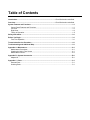
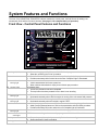
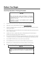
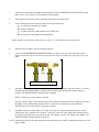
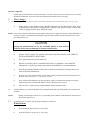
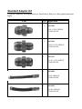
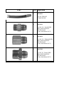
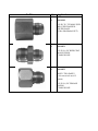
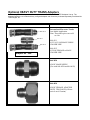
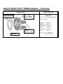
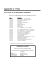
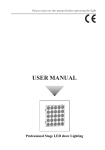
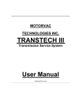
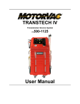
MOTORVAC
TECHNOLOGIES INC.
INDUSTRIAL
TRANSTECH
Transmission Service System
Operator Manual
PDF VERSION
Table of Contents
Introduction............................................................................................... Error! Bookmark not defined.
Overview.................................................................................................... Error! Bookmark not defined.
System Features and Functions...................................................................................................... 1-1
Control Panel Features and Functions ......................................................................................... 1-1
Left View ....................................................................................................................................... 1-3
Right View…………………………………………………………………………………………………1-4
Theory of Operation………………………………………………………………………………………1-5
Safety Information............................................................................................................................. 2-1
Before You Begin .............................................................................................................................. 3-1
First Time Operation ..................................................................................................................... 3-1
Transmission Service Procedure .................................................................................................... 4-1
Troubleshooting and Additional Help ............................................................................................. 5-1
Appendix A - Maintenance ...............................................................................................................A-1
Maintenance Procedures..............................................................................................................A-1
Cleaning the Unit’s Filter Screen ………………………………………………………………………A-1
Maintenance Record.....................................................................................................................A-3
Appendix B - System Accessories ..................................................................................................B-1
Adapter Kit …………………………………...…………………………………………………..………B-1
Appendix C - Parts ............................................................................................................................C-1
External Parts ..............................................................................................................................C-1
Ordering Parts……………………………………………………………………………………………C-1
System Features and Functions
The front of the INDUSTRIAL TRANSTECH cabinet contains the control panel, the fluid fill neck for adding new
transmission fluid, and the fluid level windows. (See page 1-4 for complete theory of operation)
Front View - Control Panel Features and Functions
A
G
B
H
C
I
D
J
E
K
F
A. Change Fluid button
B. Drain button
C. Low Vehicle Fluid
warning light
• Starts exchanging used fluid for new fluid / Service in progress mode.
• Starts the unit during the “Prime” procedure.
• Drains fluid from vehicle’s transmission when performing the drain pan procedure.
• Provides momentary drain function when the units “Complete” light is illuminated.
Illuminates when:
• Vehicle transmission fluid is two quarts low.
• When vehicles transmission is empty at end of drain pan procedure.
D. Complete light
Illuminates when:
• The service procedure has been completed
• The stop button has been pressed & unit’s alarm is not sounding
E. Engine – Start /On
warning light
•
•
Flashes when the vehicle’s engine needs to be started.
Illuminated constantly when vehicle’s engine is running & the unit senses fluid pressure.
F. Engine - Stop/Off
warning light
•
•
Flashes when the vehicle’s engine needs to be stopped.
Illuminated constantly when the vehicle’s engine is OFF.
G. Fill button
• Adds a pre-programmed amount of fluid to the transmission at beginning of service.
• Adds a pre-programmed amount of fluid to the transmission after the Drain procedure.
• Provides momentary fill function when the unit’s Complete light is illuminated.
Illuminates when the clean fluid tank in the machine is empty / “zero” level.
H. Low Clean Fluid
warning light
I. Fill- Additional fluid
count lights
J. Stop button
K. Empty Waste button
Will illuminate according to the amount of pre-programmed fluid that will be added.
• Stops units pump & completely resets unit (if alarm is not sounding).
• Stops units alarm if alarm is sounding.
Empties used transmission fluid from the unit’s waste tank.
Left View:
A
E
B
F
C
G
D
A.
Adaptor Tray
Used to store the unit’s adaptors.
B.
Output / Return Hose
Connects to the Transmission’s cooling system.
C.
Disposal Hose
Inserts into the shop’s fluid recycling receptacle or into a suitable container
approved for storing used transmission fluid.
D.
Serial Number Plate
Identifies the unit’s model & specific manufacturer’s production number.
E.
Tank filler neck
(Not shown)
Quick Coupler
Access port to add new transmission fluid to the unit’s new fluid tank.
Disposal Hose Check
Valve
Prevents excessive drainage from waste hose, opens automatically when EMPTY
WASTE button is pushed.
F.
G.
Secures the needed service adaptors to the unit’s output / return hose assemblies.
Right View:
A
D
B
C
A.
Output / Return Hose
Connects to the Transmission’s cooling system.
B.
External Power Harness w/
Battery Clamps
Positive + (Red) battery connection.
Negative - (Black) battery connection.
C.
Quick Coupler
Secures the needed service adaptors to the unit’s output / return hose assemblies.
D.
Adaptor Tray
Used to store the unit’s service adaptors.
Theory of Operations
Detailed descriptions of the various operations, control buttons, and indicators that make up the control panel are
listed below.
OFF MODE:
•
When the unit is connected to power, an alarm will sound indicating power-up. Fluid will be
re-circulated to the vehicle’s transmission.
•
When the vehicle is started, the unit will sound an alarm indicting that fluid and pressure from the vehicle
have reached the machine and it is ready for service.
CHANGE FLUID:
If pressed before draining the transmission pan (at beginning of service), the unit will automatically rout the
used fluid from the vehicle’s transmission into the unit’s WASTE tank, and supply an equal amount of new fluid
from the unit’s CLEAN fluid tank to the vehicle.
•
If pressed after the transmission fluid was drained using the DRAIN button, the machine will add to the
transmission the equal amount of fluid collected during the drain mode, plus the amount entered manually
using the FILL button (see FILL section), once this amount is added to the transmission, an alarm will sound
and the ENGINE START light will flash. At this time the technician should start the engine. Once started,
the machine will automatically rout the used fluid to the WASTE tank and supply new fluid into the
vehicle’s transmission.
Note: Fluid level in the transmission may vary during service. Level will be adjusted automatically at end
of service.
•
If pressed and held while power is connected to unit, the unit’s computer will commence the PRIME
mode. This procedure is used any time the waste tank is drained completely.
DRAIN:
•
If pressed at beginning of service, fluid will be drained from the vehicle’s transmission into the machine’s
WASTE tank until no fluid is received from the vehicle’s transmission. An alarm and ENGINE STOP light
will be activated when the transmission fluid pan is empty.
•
The machine’s computer will account for the amount of fluid collected in the WASTE tank during the
DRAIN mode.
•
If pressed after service, (The COMPLETE light is lit), fluid will drain only as long as the button is pressed,
flow will stop when the button is released.
FILL:
•
If pressed at beginning of service, for every time pressed the unit count ½ of a quart, a light will turn ON to
indicate the amount entered (see chart in this section). The unit will automatically add the amount of fluid
indicated to the overall fluid level of the transmission.
EXAMPLE: When the technician checks the transmission’s fluid level before beginning the service, and the
level in the transmission is ½ of a quart low, the FILL button should be pressed once. The light above the ½
qt. indicator will light. This amount of fluid will automatically be added to the transmission during the
service. The alternative action would be for the technician to add the correct amount of fluid manually to the
transmission, before starting the service.
•
If pressed after DRAIN mode, the unit will add the amount of fluid entered according to the lights that are
lighted under the FILL button (see chart in this section).
EXAMPLE: When the transmission fluid pan is to be removed, the technician will press the DRAIN button,
the unit will empty fluid until the filter cannot pull any from the pan. Once the pan is removed there will be
some fluid left at the bottom of the pan, this fluid is emptied manually into the shop’s recycling container.
When this happens, the machine will not account for the fluid that was removed manually. The technician
should calculate the amount of fluid removed manually, then press the FILL button according to the amount
calculated.
•
If pressed when the COMPLETE light is ON, but the LOW CLEAN FLUID light is OFF, First press,
the pump will run continuously. Second press, ½ qt. light will turn on, the unit will add half of a quart and
stop automatically. Press three times, the 1 qt light will turn on and the unit will add one full quart and stop
automatically etc,. See chart below.
FILL- ADDITIONAL FLUID COUNT LIGHTS:
First light on = 1/2 qt.
Second light on = 1 qt.
First and second lights on = 1 ½ qts.
Third light on = 2 qts.
Third and first lights on = 2 ½ qts.
Third and second lights on = 3 qts.
All lights on = 3 ½ qts. / Maximum fluid added automatically.
Pressing the Fill button once more will turn all lights off.
LOW CLEAN FLUID:
•
The light will be on when the CLEAN FLUID tank is empty.
COMPLETE:
•
The COMPLETE light will turn on when clean fluid tank is empty or the STOP button is pressed. The unit
will automatically revert to re-circulating mode.
ENGINE START/ON:
•
The light will flash if the engine needs to be started to continue
•
The light will be on constantly when the engine is running or if the machine’s system is pressurized over 4
psi.
ENGINE STOP/OFF:
•
The light will flash if the engine needs to be stopped/turned off.
•
The light will be on constantly when the engine is not running.
EMPTY WASTE:
•
The light will be on when the waste fluid is at/or over 4 quarts in the WASTE tank. The unit will not run
unless the level in the waste tank is less than ¼ full (approximately 4 qts.).
STOP:
•
Will turn off an alarm without stopping the service when sounding.
•
Will stop the pump and revert the system to recirculating mode, (if no alarm is sounding).
NOTE: If the unit needs to be stopped completely while an alarm is sounding, press the STOP button TWICE.
The first press will stop the alarm and the second press will stop the pump.
Safety Information and Precautions
/!\ DANGER
Vehicle exhaust gases contain Carbon Monoxide, which is a colorless and odorless lethal gas.
Only run engines in well-ventilated areas and avoid breathing exhaust gases.
Extended breathing of exhaust gases will cause serious injury or death.
/!\ WARNING
Exhaust gases, moving parts, hot surfaces are present during and after the vehicle’s engine is running.
Read and understand the operator’s manual before using the TRANSTECH Service system.
When using petroleum products always refer to the MSDS sheets and manufacturer’s instructions for the
proper procedure to handle emergency medical treatment, cleanup, handling, and storage requirements.
Improper use of the INDUSTRIAL TRANSTECH Transmission Service System or exposure to exhaust gases can
cause injury.
Spilled transmission fluid on an engine can ignite.
Avoid exposure to flames, sparks, hot engine parts, and other ignition sources.
Always keep fully charge fire extinguisher nearby. The extinguisher should have a class B rating and be
suitable for gasoline, chemical, and electrical fires.
Cleanup any oil spills immediately.
Dispose of contaminated cleanup material according to governing environmental laws.
Never look directly into the air induction plenum or carburetor throat when the engine is operating.
Always verify hose connections to the transmission’s oil cooler lines before starting the vehicle’s
engine.
Explosion or flame or exposure to flammable liquid and vapors can cause injury.
Flammable liquid (transmission fluid) can splash out of reservoir when filling or when unit is being moved.
Always keep Reservoir Cap secure except when filling reservoir.
Explosion or flame can cause injury.
Transmission cooling systems may maintain residual pressure in connection lines to and from transmission and
cooler radiator even after the engine has been turned off.
Wear safety goggles.
Wear chemical resistant gloves when connecting or disconnecting fitting and adapters.
Chemicals can cause harmful byproducts - do not add any chemicals to INDUSTRIAL TRANSTECH’s reservoir
tank.
Use only approved automatic transmission fluid.
Do not swallow or ingest any chemicals.
Use with adequate ventilation. Avoid breathing vapors.
Do not store chemicals in or on the machine (other than automatic transmission fluid).
Improper use of transmission fluid can cause injury.
Over exposure can have harmful effect on eyes, skin, respiratory system and possible unconsciousness and
asphyxiation.
Improperly blocked vehicles can move.
Set the parking brake and chock the wheels.
Moving vehicles can cause injury.
Moving engine parts.
The engine cooling fan will cycle on and off depending on the coolant temperature and could operate without the
engine running.
Wear safety goggles.
Always keep objects, clothing, and hands away from the cooling fans and engine parts.
Moving engine parts can cause injury.
Hot surfaces are present during and after running the engine.
Do not contact hot surfaces such as, manifolds, pipes, mufflers, catalytic converters, or radiators and
hoses.
Hot surfaces can cause injury.
Catalytic converters become extremely hot.
Do not park a converter-equipped vehicle over dry grass, leaves, paper, or any other flammable material.
Do not touch a catalytic converter until the engine has been off for at least 45 minutes.
Catalytic converters can cause burns.
Cracked fan blade can become airborne.
Examine fan blades for cracks. If found, do not service the vehicle.
Flying objects can cause injury.
Batteries produce explosive gases and can explode.
Wear safety goggles when working on or near batteries.
Use in a well-ventilated area.
Keep sparks and flames away from the battery and never lay tools, equipment, or other conductive
objects on the battery.
When tools or equipment are connected to the battery, make sure the equipment power switch is off.
Connect the positive lead of the equipment to the positive lead battery first; connect the negative lead of
the equipment to a solid ground point as far from the battery as possible.
Keep battery acid away from skin or eyes. In case of eye contact, flush with clean water for 15 minutes
and get medical attention.
Battery explosion and ignited gases can cause injury.
Before You Begin
First Time Operation / Priming Procedure
NOTE
This unit has been tested with Dextron lll Automatic
Transmission Fluid, and is ready for service after receiving
inspection of the unit.
Remember to send in your warranty card to properly
register your machine.
1.
Check the output/return hoses, battery connections, and all external components for damage.
2.
Fill the unit’s reservoir with a minimum of 20 quarts of new transmission fluid.
3.
Connect two compatible adapters to each other, secure tightly. Attach the output/return hoses together
using the proper adapters.
4.
Insert the Disposal hose into the unit filler neck (or into a suitable container if the unit has been used to
service a vehicle previously).
5.
Attach the unit’s black ( ) negative battery clip to a solid ground point as far from the battery as
possible, (do not connect the positive battery connector yet).
6.
Press the and hold CHANGE FLUID button, connect the positive power harness clamp to the vehicle’s
12 volt battery, allow the unit to run until the EMPTY WASTE light begins to flash, then press STOP.
7.
Press the EMPTY WASTE button, let unit run until it stops automatically.
8.
Press the DRAIN button to release pressure contained within the output/return hoses.
9.
Disconnect power to machine and check new transmission fluid level, add if necessary.
10.
The unit is now ready to perform a service. See service instructions for procedure.
-
NOTE
Steps 1-9 must be performed BEFORE first time operation
and/or any time the unit’s reservoir is completely drained of
fluid.
Transmission service procedure
Follow the steps below to connect the unit to the vehicle's transmission cooler lines.
Make sure the vehicle has at least 1/8 tank of fuel before beginning this process.
IMPORTANT
Do not perform the transmission service if the
engine oil or coolant level is low.
If necessary, add motor oil and/or coolant.
vehicle’s
/!\ WARNING
Flammable Liquid can squirt out of pressurized lines when connecting or disconnecting.
Verify that engine and machine are both off before connecting or disconnecting cooler lines or
adapters.
Wear safety goggles.
Wear chemical resistant gloves when connecting or disconnecting fittings and adapters.
Wrap a shop towel around pressure fittings and adapters when disconnecting.
Avoid exposure to flames, sparks, hot engine parts, and other ignition sources.
Explosion or flame or exposure to flammable liquid and vapors can cause injury.
1.
Add the correct amount of automatic transmission fluid into the INDUSTRIAL TRANSTECH’S clean
tank reservoir. See vehicle’s service manual for fluid quantity.
2.
Start engine, let run until it reaches operating temperature, turn engine OFF.
3.
Locate and disconnect the cooler line at the easiest connection point:
•
•
•
•
At cooler line connection to radiator.
At heat exchanger.
At filter connection, (Side marked OUT of filter base)
At cooler line connecting to the transmission.
NOTE: Adapters are connected to either cooler line, “from” or “to” the radiator and/or the transmission.
4.
Install the proper adapters onto the disconnected lines.
5.
Connect the FLOW DIRECTION INDICATOR LOOP (“H” adapter) to the previously attached cooler line
adapters. NOTE: The ball valve must be in the closed position. (The valve handle is at a right angle to flow.) See
photo.
Valve
Closed
Part #200-8100 Patent Pending
6.
Attach the unit to the vehicle's battery by connecting the unit's red battery clip to the positive (+) battery
terminal and connecting the black (-) battery clip to a solid ground point as far from the battery as
possible. The ENGINE START/ON light will be flashing.
NOTE: Connect to 24 volts whenever possible.
7.
Start the vehicle’s engine. Note the direction of flow, (dirty oil) from the cooler lines (right or left side of
the adapter). After determining direction of flow, rotate the valve handle 90° counterclockwise.
Transmission is now in closed loop (or bypass) operation.
8.
Attach the units hose marked “Dirty Oil” to the side of the “H” adapter that indicated flow from the
vehicle (dirty side). Attach the hose marked “Clean Oil” to the side of the adapter that indicated flow to
the vehicle. Once unit’s lines are connected to the “H” adapter, close the “H” adapter valve handle. The
ENGINE START/ON light should be ON solid.
NOTE: Transmission fluid will circulate through the unit and return to the vehicle’s transmission when unit is off
(bypass mode).
If no flow is indicated;
And the start-up alarm does not sound when the engine is started, or the unit does not commence service when the
CHANGE FLUID button is pressed. Check filter and transmission fluid cooler for blockage.
9.
Filter Change:
If the vehicle’s transmission pan is to be removed, perform the following steps before removal of the transmission oil pan. If not, go to step 8.
a)
Follow steps 1-6, note fluid level in the WASTE tank, then press the Drain button, allow 10 qts.
of fluid to drain if the vehicle is equipped with a “shallow” pan. Drain 12-14 qts. of fluid if the
vehicle is equipped with a “deep” transmission pan.
NOTE: It is possible to drain the transmission pan through the drain plug if so equipped. If the pan is drained manually, it is
necessary to add new transmission fluid manually trough the normal channel, (usually the dipstick tube), before
proceeding with service.
CAUTION
Letting the transmission run for an extended period of time without
fluid can cause serious damage to internal components.
10.
b)
Stop the vehicle’s engine. The machine will sound an alarm and flash the LOW VEHICLE
FLUID and ENGINE STOP/OFF lights.
c)
Press STOP button once to turn alarm off.
d)
Replace or clean the vehicle’s transmission fluid filter, (if applicable), and reinstall the
transmission’s oil pan as per shops repair manual and manufacturer’s recommendations.
e)
Note the approximate amount of fluid removed from the transmission’s fluid pan after it was
removed from the transmission.
f)
Press the unit’s FILL button according to approximate amount of fluid removed from the transmission’s
fluid pan, (step c), Press Once = ½ qt. Twice = 1 qt Etc.
g)
Press CHANGE FLUID button. The unit will fill the vehicle’s transmission according to the amount
emptied into the unit’s WASTE tank and the amount of fluid entered from step f).
h)
Start the vehicle’s engine when the START ENGINE flashes and alarm sounds.
Continue with the service until all fluid has been exchanged and the unit stops automatically. Press STOP to turn
off alarm.
NOTE:
11.
Quantity of fluid used per vehicle may vary depending on the condition of the fluid in the transmission of
the vehicle being serviced.
Let engine run for one minute, then check the transmission’s fluid level.
If level is low:
a)
Press and hold the FILL button for 5-10 seconds.
b)
Re-check fluid level, repeat step “a)” if necessary.
If level is high:
c)
Press and hold the DRAIN button for 5-10 seconds.
d)
Re-check fluid level, repeat step “ c) ” if necessary.
Stop engine and let cool off if necessary.
12.
Disconnect hoses from the INDUSTRIAL TRANSTECH and connect the vehicle’s cooler lines to their original
connection ports.
13.
Start the engine, check cooler lines for leaks, and re-tighten as necessary.
14.
Step on the foot brake firmly, then slowly shift the gear lever to Low Gear (first gear) then back to Park. Check the
transmission’s fluid level, adjust if necessary.
Service tip:
A)
To minimize fluid mixture, a “Pan Drain” procedure may be performed, (without removing the
transmission pan).
Follow steps 1-6 from this section.
Perform Filter change procedure steps: a), b), c), g), h).
C)
Continue with steps 8 & 9.
Troubleshooting and Additional Help
Refer to the list below in the unlikely event that you have problems with your
INDUSTRIAL TRANSTECH Transmission Service System.
Problem:
1. Unit does not power-up, no LEDs are
lighted
Solution:
Polarity is reversed on vehicle battery connection.
Check connection to battery for a loose condition.
2. Unit does not sound the start-up alarm
No fluid/pressure is reaching the machine. See
Transmission Service Procedure, page 4-2 steps a, b,
and c. also see steps 3 and 4 of this page.
3. The start-up alarm sounds, and an
intermittent alarm sounds 30-40 seconds
after pressing the Change Fluid button.
Fluid flow is extrmely slow, but enough to pressure
the system to 4 psi. service ports are opened when
Change Fluid is pressed, then pressure drops
completely, this will trigger the alarm. Verify flow.
See Transmission Service Procedure, page 4-2 steps
a, b, and c. See steps 2 & 4, of this page.
4. Unit stops and alarm sounds 30 - 40
seconds after pressing the Drain button
No fluid is being received in unit’s WASTE tank,
Check hose connections to adapters
Check adapters for a kinked condition.
Check vehicle’s fluid flow. See: Transmission
Service procedure, page 4-2 steps a, b and c.
See steps 2 and 3 of this page.
5. An intermittent alarm sounds during the
Transmission Service Procedure, and
the ENGINE STOP light is flashing.
The transmission fluid level is low 2 qts. press STOP
button Once, this will stop the alarm, but not the
unit’s pump. Check transmission fluid level, stop
engine if fluid is low enough that the dipstick does
not reach to measure fluid. The unit will sound an
alarm when fluid has reached the proper level, start
engine and proceed with service. Check hose
conncetions to adapters for proper connection, check
adapters and hoses for a kinked condition.
6. The level in the transmission is 2 qts.
low after service.
The low level switch from the WASTE tank may
have become disconnected previous to starting the
service. Insert unit’s Drain Hose into a waste oil
recycling container. Press DRAIN WASTE button.
Verify that the pump stops automatically and that
fluid level is still visible though the visual level
window. If not, remove unit’s back panel and check
waste tank level switch wire connctions.
7. New fluid is above the 2qt. line, but the
LOW CLEAN FLUID light is ON.
The low level switch on the new fluid tank has
become disconnected. Remove unit’s back panel
and check the clean tank level switch wire
connections.
8. The unit performs poorly.
Check all hoses and wires for cuts or frays.
Check cabinet for dents or impact markings.
Verify that the filter screen has recently been
cleaned. (Refer to the maintenance log in
Appendix A to view dates of services performed.)
ADDITIONAL HELP
Please verify that items 1-6 above have been reviewed before calling for
additional assistance.
In the unlikely event that problems persist with the unit call
Technical Support, have your model and serial numbers available before
you call. Remember to send in your warranty card.
In the U.S.
(800) 841-8810
Outside the U.S.
Call your local distributor
Standard Adapter Kit
The most commonly used application are listed below; however, other applications may
apply.
PART
Qty
1
Application
064-3008
#8 X # 12 JIC NIPPLE
COOLER LINE
1
064-3010
#10X X 12 JIC NIPPLE
COOLER LINE
1
064-3012
#12 X # 12 JIC NIPPLE
COOLER LINE
1
064-4008
#8 JIC FEMALE
COOLER LINE
1
064-4010
#10 JIC FEMALE
COOLER LINE
PART
Qty
Application
2
064-4012
#12 JIC FEMALE
COOLER LINE
1
064-3034
#10 JIC X ¾” MALE PIPE
HEAT EXCHANGER /
FILTER BASE
(Filter Side Marked OUT)
1
064-4034
#12 JIC X ¾” FEMALE PIPE
HEAT EXCHANGER /
FILTER BASE
(Filter Side Marked OUT)
1
064-3100
#12 JIC X 1” MALE PIPE
HEAT EXCHANGER /
FILTER BASE
(Filter Side Marked OUT)
PART
Qty
Application
1
064-4100
#12 JIC X 1” FEMALE PIPE
HEAT EXCHANGER /
FILTER BASE
(Filter Side Marked OUT)
1
064-4021
#12 X #16, JIC REDUCING
MALE UNION
COOLER LINE
1
064-4022
NOTE: TWO PARTS
(#16 nut swivels on #12
union)
#12 X #16, JIC FEMALE
UNION
COOLER LINE
Optional HEAVY DUTY TRANS Adapters
The following TRANS adapters have been added to the INDUSTRIAL TRANSTECH adaptor line-up. The
adapters listed are not included with any configured adapter sets & must be purchased separately from MotorVac
Technologies, Inc.
PART & NO.
APPLICATION
064-4112
International Harvester Trucks
Late Model Application
Note: These three pieces are sold
as a kit.
064-4111
064-4112
Adaptor Kit - 200-
064-4111
#12 X #12, SAE MALE UNION
COOLER LINE
064-4112
#12 SAE FEMALE to MALE
COOLER LINE
064-3020
#20 JIC MALE NIPPLE
(Use with 064-4020 and 064-4012)
064-4020
#20 JIC FEMALE ADAPTOR
NOTE: TWO PARTS (#20 nut
swivels on #12 union)
Optional HEAVY DUTY TRANS Adapters - Continued
PART & NO.
064-4114 Plate
(080-1201 O’Ring)
050-1931 Base
1 1/8” x 16 THD
(080-1202 O’Ring)
APPLICATION
200-1033
545 ALLISON TRANSMISSION WITH
SPIN-ON FILTER:
064-4115
#12 JIC x ½” MPT
200-1033
Baldwin……BT230
Donaldson…P55-5570
Fleetguard….LF3342
Fram……….PH3519A
Luberfiner….LFP5570
Wix………..51268
NOTE: Use hoses #064-4012
(In Standard Adaptor Kit)
Appendix C - Parts
Service Parts for the INDUSTRIAL TRANSTECH
Please refer to the part numbers below when ordering parts for the unit.
Part #
010-6106
010-6107
011-0060
010-1030
100-8702
010-6060
011-0062
020-1019
020-1601
040-0612
040-0613
040-0623
040-1200
040-2000
040-2200
050-3001
060-5810
080-0243
200-8732
200-8612
200-8236
200-3107
Description
Swivel caster (5” dia.), non-locking
Swivel caster (5” dia.), with wheel lock
Hose bracket, black texture
Adapter Box
16oz Bottle for Adaptor Box
Reservoir cap
Handle, black texture
Harness, power
Internal Light
Screw, Allen Head, ¼-20 x ½ (Handle)
Screw, Phillips, stainless steel 6-32 (Rear panel)
Screw, Allen Head, 8-32 x 5/8 (Control Panel)
Screw 5/8 php x #6 (for adapter box)
Flat washer #6 (for adapter box)
Threaded Standoff (for adapter box)
Check valve, (disposal hose)
Cap plug (handle)
Female Quick Disconnect Couplers, 3/4”, Brass
Output/Return hose assembly
Disposal hose assembly
Operators Manual, Industrial Transtech
Adapter Kit (standard)
See Appendix B of this manual for individual adapter part numbers.
ORDERING PARTS
Parts for the unit may be ordered by calling
Customer Service, have your model and serial numbers
available:
In the U.S.
(800) 841-8810
(714) 558-4822
Outside the U.S.
Contact Your Local
Distributor