1
MOTORVAC
TECHNOLOGIES INC.
TRANSTECH II
Transmission Service System
User Manual
A
TRANSTECH IIA
P/N 200-8223
Rev N/C 1999
Table of Contents
Introduction ................................................................................................................................... iii
Overview ..........................................................................................................................................v
System Features and Functions ................................................................................................. 1-1
Control Panel Features and Functions..................................................................................... 1-2
Left View ................................................................................................................................. 1-3
Right View………………………………………………………………………………………………1-4
Theory of Operation……………………………………………………………………………………1-5
Safety Information ....................................................................................................................... 2-1
Before You Begin ........................................................................................................................ 3-1
First Time Operation................................................................................................................ 3-1
Transmission Service Procedure ............................................................................................... 4-1
Troubleshooting and Additional Help ........................................................................................ 5-1
Appendix A - Maintenance .......................................................................................................... A-1
Maintenance Procedures ......................................................................................................... A-1
Cleaning the Unit’s Filter Screen ……………………………………………………………………A-1
Maintenance Record................................................................................................................ A-3
Appendix B - System Accessories.............................................................................................. B-1
Adapter Kit ……………………………………………………………………………………..………B-1
Appendix C - Parts....................................................................................................................... C-1
External Parts ......................................................................................................................... C-1
Ordering Parts………………………………………………………………………………………C-1
i
Introduction
Congratulations on your selection of the TRANSTECH II Transmission Service System. By choosing
this product, you are acquiring the most technologically advanced method available for automatic
transmission service and fluid exchange.
The TRANSTECH II System is a self-contained system, designed to connect to any automatic
transmission through it’s cooling system. Once the unit is connected, it can be used to drain the fluid
from the vehicle’s transmission for filter replacement and/or to completely exchange the transmission
fluid with new fluid, without removing the vehicle’s transmission fluid pan.
With the engine idling, the unit will receive the used fluid expelled by the vehicle’s transmission fluid
pump through one of the hoses connected to the transmission cooling system, and supplies new fluid
through the second hose connected to the other side of the disconnected transmission cooling line.
It is recommended that a vehicle’s transmission lubrication system be serviced every 15,000 miles
(or according to the vehicle owner’s manual) to obtain the highest lubricant protection, to reduce
friction from internal transmission components, and thus increase the efficiency and life span of the
transmission to it’s maximum.
Please study this Operators Manual to become thoroughly familiar with the TRANSTECH II
Transmission Service System.
IMPORTANT
The TRANSTECH II Transmission Service System is designed to work
EXCLUSIVELY
with Automatic Transmission Fluid.
Use of any chemical during this process may cause operational failure of the
TRANSTECH II System and voids the manufacturer’s warranty.
See warranty card for details.
iii
Overview
This manual contains all the information you need to use the TRANSTECH II System. Please make
sure all technicians using the unit read this manual and have it within easy reach whenever the unit is
being used.
The following is a quick reference to the information in this manual:
System Features and Functions
This chapter describes the TRANSTECH II Transmission Service System’s Switches, Lights
and Connections.
Safety Information
Adhere to the safety guidelines in this chapter at all times!
Before You Begin
Follow the instructions in this chapter before using the unit for the first time.
Service Procedure
This chapter contains step-by-step setup and service procedure for using the unit to drain the
vehicle’s transmission oil pan and/ or to exchange the fluid completely.
Troubleshooting and Additional Help
Turn to this chapter in the unlikely event you have problems with your TRANSTECH II
System or need additional help.
Appendices - Maintenance, Accessories, and Parts
The appendices contain routine maintenance procedures for the TRANSTECH II System, such
as changing the filter screen, lists of available accessories, replacement parts, and the Material
Safety Data Sheet.
v
System Features and Functions
The front of the TRANSTECH II cabinet contains the control panel, the fluid fill neck for adding new
transmission fluid, and the fluid level windows.
1-1
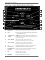
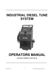
System Features and Functions
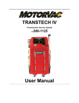
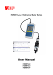
Front View - Control Panel Features and Functions
A
G
B
H
C
D
I
E
J
F
K
A.
Change Fluid
Starts exchanging used fluid for new fluid -Service in progress mode
B.
Drain
Drains fluid from vehicle’s transmission, an alarm will sound when
the transmission is empty.
Illuminates when fluid from the vehicle in service is empty or too
low.
Illuminates when service is terminated. When new fluid is empty or the
stop button has been pressed
C.
Low Vehicle Fluid
D.
Complete
E.
Engine - Start/On
Flashes when the vehicle’s engine needs to be started,
Is illuminated constant when the vehicle’s engine is running.
F.
Engine – Stop/Off
Flashes when the vehicle’s engine needs to be stopped,
Is Illuminated constant when the vehicle’s engine is OFF.
G.
Fill
Adds fluid to the transmission . See page 1-5 for more information.
H.
Low Clean Fluid
Illuminates when clean fluid in the machine is empty.
I.
Fill- Additional fluid
count lights
Illuminates according to the amount of extra fluid that will be added.
See page 1-6 (this section) for more information
J.
Stop
Stops alarm if alarm is sounding .
Stops pump if alarm is not sounding.
K
Empty Waste
Empties used fluid from machine’s waste tank.
1-2
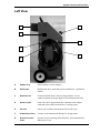
System Features and Functions
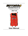
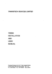
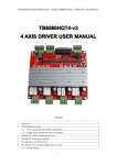
Left View
A
E
B
F
C
G
D
A.
Adapter Tray
Stores machine’s service adapters
B.
Serial plate.
Identifies the unit’s model and specific manufacturer’s production
number
C.
Disposal hose
Is inserted into the shop’s fluid recycling container or into a
suitable container for proper disposal of used transmission fluid.
D.
Quick Coupler
Secures the unit’s output/return hose connection to the adapter
connected to the vehicle's transmission ‘s cooling system.
E.
Fill neck
Access port to add new transmission fluid to unit’s tank
F.
Output/return Hose
Connects to the transmission through it’s cooling system.
G.
Drain hose check
Valve
Prevents excessive drainage from drain hose, opens automatically
When unit is in use.
1-3
System Features and Functions
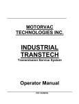
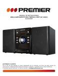
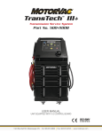
Right View
A
C
B
A.
Output/Return
Hose
Connects to the transmission’s cooling system.
B.
Quick Coupler
Secures the unit’s output/return hose connection to the adapter
connected to the vehicle's transmission’s cooling system.
C.
Battery Cables
Positive (red) and negative (black) battery connections.
1-4
System Features and Functions
Theory of Operations
Detailed descriptions of the various operations, control buttons, and indicators that make up the control
panel are listed below.
OFF MODE:
•
When the unit is connected to power, an alarm will sound indicating power-up. Fluid will be
re-circulated to the vehicle’s transmission.
•
When the vehicle is started, the unit will sound an alarm indicting that fluid and pressure from the
vehicle have reached the machine and it is ready for service.
CHANGE FLUID:
•
If pressed before draining the transmission pan (at beginning of service), the unit will
automatically rout the used fluid from the vehicle’s transmission into the unit’s WASTE tank, and
supply an equal amount of new fluid from the unit’s CLEAN fluid tank to the vehicle.
•
If pressed after the transmission fluid was drained using the DRAIN button, the machine will
add to the transmission the equal amount of fluid collected during the drain mode, plus the amount
entered manually using the FILL button (see FILL section), once this amount is added to the
transmission, an alarm will sound and the ENGINE START light will flash. At this time the
technician should start the engine. Once started, the machine will automatically rout the used fluid
to the WASTE tank and supply new fluid into the vehicle’s transmission.
Note: Fluid level in the transmission may vary during service. Level will be adjusted automatically at
end of service.
DRAIN:
•
If pressed at beginning of service, fluid will be drained from the vehicle’s transmission into the
machine’s WASTE tank until fluid is depleted from the transmission pan. An alarm and ENGINE
STOP light will be activated when the transmission fluid pan is empty.
•
The machine’s computer will account for the amount of fluid collected in the WASTE tank during
the DRAIN mode.
•
If pressed after service, (The COMPLETE light is lit), fluid will drain only as long as the button
is pressed, flow will stop when the button is released.
FILL:
•
If pressed at beginning of service, for every time pressed the unit count ½ of a quart, a light will
turn ON to indicate the amount entered (see chart in this section). The unit will automatically add
the amount of fluid indicated to the overall fluid level of the transmission.
1-5
System Features and Functions
EXAMPLE: When the technician checks the transmission’s fluid level before beginning the
service, and the level in the transmission is ½ of a quart low, the FILL button should be pressed
once. The light above the ½ qt. indicator will light. This amount of fluid will automatically be
added to the transmission during the service. The alternative action would be for the technician to
add the correct amount of fluid manually to the transmission, before starting the service.
•
If pressed after DRAIN mode, the unit will add the amount of fluid entered according to the
lights that are lighted under the FILL button (see chart in this section).
EXAMPLE: When the transmission fluid pan is to be removed, the technician will press the
DRAIN button, the unit will empty fluid until the filter cannot pull any from the pan. Once the pan
is removed there will be some fluid left at the bottom of the pan, this fluid is emptied manually into
the shop’s recycling container. When this happens, the machine will not account for the fluid that
was removed manually. The technician should calculate the amount of fluid removed manually,
then press the FILL button according to the amount calculated.
•
If pressed when the COMPLETE light is ON, but the LOW CLEAN FLUID light is OFF,
First press, the pump will run continuously. Second press, ½ qt. light will turn on, the unit will
add half of a quart and stop automatically. Press three times, the 1 qt light will turn on and the
unit will add one full quart and stop automatically etc,. See chart below.
FILL- ADDITIONAL FLUID COUNT LIGHTS:
First light on = 1/2 qt.
Second light on = 1 qt.
First and second lights on = 1 ½ qts.
Third light on = 2 qts.
Third and first lights on = 2 ½ qts.
Third and second lights on = 3 qts.
All lights on = 3 ½ qts.
Maximum fluid added automatically.
Pressing the Fill button once more will turn all lights off.
LOW CLEAN FLUID:
•
1-6
The light will be on when the CLEAN FLUID tank is empty.
System Features and Functions
COMPLETE:
•
The COMPLETE light will turn on when clean fluid tank is empty or the STOP button is pressed.
The unit will automatically revert to re-circulating mode.
ENGINE START/ON:
•
The light will flash if the engine needs to be started to continue
•
The light will be on constantly when the engine is running or if the machine’s system is pressurized
over 4 psi.
ENGINE STOP/OFF:
•
The light will flash if the engine needs to be stopped/turned off.
•
The light will be on constantly when the engine is not running.
EMPTY WASTE:
The light will be on when the waste fluid is at/or over 4 quarts in the WASTE tank. The unit will not
run unless the level in the waste tank is less than ¼ full (approximately 4 qts.).
STOP:
•
Will turn off an alarm without stopping the machine when an alarm sounds during the CHANGE
FLUID mode.
•
Will stop the pump and revert the system to recirculating mode.
NOTE: If the unit needs to be stopped completely while an alarm is sounding, press the STOP button
TWICE. The first press will stop the alarm and the second press will stop the pump.
1-7
Safety Information and Precautions
/!\ DANGER
Vehicle exhaust gases contain Carbon Monoxide, which is a colorless and odorless lethal gas.
Only run engines in well-ventilated areas and avoid breathing exhaust gases.
Extended breathing of exhaust gases will cause serious injury or death.
/!\ WARNING
Exhaust gases, moving parts, hot surfaces are present during and after the vehicle’s engine is running.
Read and understand the operator’s manual before using the TRANSTECH Service system.
When using petroleum products always refer to the MSDS sheets and manufacturer’s
instructions for the proper procedure to handle emergency medical treatment, cleanup,
handling, and storage requirements.
Improper use of the TRANSTECH Transmission Service System or exposure to exhaust gases can
cause injury.
Spilled transmission fluid on an engine can ignite.
Avoid exposure to flames, sparks, hot engine parts, and other ignition sources.
Always keep fully charge fire extinguisher nearby. The extinguisher should have a class B
rating and be suitable for gasoline, chemical, and electrical fires.
Cleanup any oil spills immediately.
Dispose of contaminated cleanup material according to governing environmental laws.
Never look directly into the air induction plenum or carburetor throat when the engine is
operating.
Always verify hose connections to the transmission’s oil cooler lines before starting the
vehicle’s engine.
Explosion or flame or exposure to flammable liquid and vapors can cause injury.
Flammable liquid (transmission fluid) can splash out of reservoir when filling or when unit is being
moved.
Always keep Reservoir Cap secure except when filling reservoir.
Explosion or flame can cause injury.
Transmission cooling systems may maintain residual pressure in connection lines to and from
transmission and cooler radiator even after the engine has been turned off.
Wear safety goggles.
Wear chemical resistant gloves when connecting or disconnecting fitting and adapters.
2-1
Safety Information
Chemicals can cause harmful byproducts - do not add any chemicals to TRANSTECH’s reservoir
tank.
Use only approved automatic transmission fluid.
Do not swallow or ingest any chemicals.
Use with adequate ventilation. Avoid breathing vapors.
Do not store chemicals in or on the machine (other than automatic transmission fluid).
Improper use of transmission fluid can cause injury.
Over exposure can have harmful effect on eyes, skin, respiratory system and possible
unconsciousness and asphyxiation.
Improperly blocked vehicles can move.
Set the parking brake and chock the wheels.
Moving vehicles can cause injury.
Moving engine parts.
The engine cooling fan will cycle on and off depending on the coolant temperature and could operate
without the engine running.
Wear safety goggles.
Always keep objects, clothing, and hands away from the cooling fans and engine parts.
Moving engine parts can cause injury.
Hot surfaces are present during and after running the engine.
Do not contact hot surfaces such as, manifolds, pipes, mufflers, catalytic converters, or
radiators and hoses.
Hot surfaces can cause injury.
Catalytic converters become extremely hot.
Do not park a converter-equipped vehicle over dry grass, leaves, paper, or any other
flammable material.
Do not touch a catalytic converter until the engine has been off for at least 45 minutes.
Catalytic converters can cause burns.
Cracked fan blade can become airborne.
Examine fan blades for cracks. If found, do not service the vehicle.
Flying objects can cause injury.
Batteries produce explosive gases and can explode.
Wear safety goggles when working on or near batteries.
Use in a well-ventilated area.
Keep sparks and flames away from the battery and never lay tools, equipment, or other
conductive objects on the battery.
2-2
Safety Information
When tools or equipment is connected to the battery, make sure the equipment power switch
is off. Connect the positive lead of the equipment to the positive lead battery first; connect
the negative lead of the equipment to a solid ground point as far from the battery as possible.
Keep battery acid away from skin or eyes. In case of eye contact, flush with clean water for
15 minutes and get medical attention.
Battery explosion and ignited gases can cause injury.
2-3
Before You Begin
First Time Operation
NOTE
This unit has been tested with Dextron lll
Automatic Transmission Fluid, and is ready for
service after receiving inspection of the unit.
Remember to send in your warranty card to
properly register your machine.
1.
Check the output/return hoses, battery connections, and all external components for damage.
2.
Attach the unit’s power harness to a motor vehicle battery by connecting the red battery clip to
-
the positive (+) battery terminal and connect the black ( )battery clip to a solid ground point as
far from the battery as possible.
3.
Fill the unit’s reservoir with a minimum of 12 quarts (11 liters) of new transmission fluid.
4.
Connect adapters 060-1200 & 060-1500 secure tightly with a clamp. Connect the
output/return hoses together using the attached adapters.
5.
Press the CHANGE FLUID button, let run for 15 seconds then press STOP. Verify that the
COMPLETE light is on.
6.
Press the CHANGE FLUID button once again, let unit run until fluid is between 1-2 quarts on
the WASTE FLUID TANK, press STOP.
7.
Insert the Disposal hose into the unit filler neck (or into a suitable container if the unit has been
used to service a vehicle previously).
8.
Press the EMPTY WASTE button, let unit run until it stops automatically.
9.
The unit is now ready to perform a service. See service instructions for procedure.
NOTE
Steps 4-8 must be performed BEFORE first
time operation and/or any time the unit’s
reservoir is completely drained of fluid.
3-1
Transmission service procedure
Follow the steps below to connect the unit to the vehicle's transmission cooler lines.
Make sure the vehicle has at least 1/8 tank of fuel before beginning this process.
IMPORTANT
Do not perform the transmission service if the
vehicle’s engine oil or coolant level is low.
If necessary, add motor oil and/or coolant.
/!\ WARNING
Flammable Liquid can squirt out of pressurized lines when connecting or
disconnecting.
Verify that engine and machine are both off before connecting or
disconnecting cooler lines or adapters.
Wear safety goggles.
Wear chemical resistant gloves when connecting or disconnecting fittings and
adapters.
Wrap a shop towel around pressure fittings and adapters when disconnecting.
Avoid exposure to flames, sparks, hot engine parts, and other ignition
sources.
Explosion or flame or exposure to flammable liquid and vapors can cause injury.
4-1
Transmission Service Procedure
1.
Add the correct amount of automatic transmission fluid into the TRANSTECH’S clean tank
reservoir. See; Approximated flush chart after step 9.
2.
Start engine, let run until it reaches operating temperature, turn engine OFF.
3.
Locate and disconnect the cooler line at the easiest connection point:
I.
At cooler line connection to radiator. Connection is usually accessible from the top
corner of the radiator (could be on either top side).
II.
At clamped rubber hose connection to transmission cooler (connections are usually
accessible from the under side of the vehicle (cooler is usually in front of radiator).
III.
At cooler line connecting to the transmission.
NOTE: Adapters can be connected to either cooler line, “from” or “to” the radiator and/or the
transmission. The TRANSTECH II will adjust to flow direction when in use.
4.
Install the proper adapters onto the disconnected lines. Attach the unit’s output/return hoses to
adapters. (either hose to either adapter)
5.
Attach the unit to the vehicle's battery by connecting the unit's red battery clip to the positive
(+) battery terminal and connecting the black (-) battery clip to a solid ground point as far from
the battery as possible. The ENGINE START/ON light should be flashing.
6.
Start the vehicle’s engine. ENGINE START/ON should be ON constantly and a beep should
sound (this indicates that the unit is ready for service, and knows the proper direction to run).
NOTE: Transmission’s fluid will be automatically re-circulated when unit is off.
If no flow is indicated;
The start-up alarm does not sound when the engine is started, or the unit’s alarm sounds
intermittently and the Engine Start lights is flashing when the CHARGE FLUID is pressed.
Flow may be achieved by performing one of the following procedures (a, b, or c). Also, See
troubleshooting section page 5-1 steps 2, 3 & 4 for additional formation of no flow cause.
4-2
a)
Accelerate the vehicle’s engine to approximately 1,500 RPM.
b)
Verify that the vehicle’s parking brake is set, then place the gear lever in neutral.
c)
Verify that the vehicle’s parking brake is set, press and hold the vehicle’s foot brake
firmly then place the gear lever in drive.
Transmission Service Procedure
7.
Filter Change:
If the vehicle’s transmission filter is to be replaced, perform the following steps before
removal of the transmission oil pan. If not, go to step 8.
a)
Follow steps 1-6, press the Drain button on the unit’s control panel. Let the engine run
until the unit’s alarm sounds the Vehicle Low Fluid and ENGINE STOP/OFF lights
are flashing. This means that the transmission has emptied most of the fluid from the
transmission’s fluid pan. Stop engine.
CAUTION
Do not let the engine run for more than one minute after
the Low Vehicle Fluid light has lit, indicating a low fluid
level in the transmission. Letting the transmission run
for an extended period of time without fluid can cause
serious damage to internal components.
b)
Replace or clean the vehicle’s transmission fluid filter and reinstall the transmission’s
oil pan as per shops repair manual and manufacturer’s recommendations.
c)
Note the approximate amount of fluid removed from the transmission’s fluid pan after
it was removed from the transmission.
d)
Press the unit’s FILL button according to approximate amount of fluid removed from
the transmission’s fluid pan, (step c), Press Once = ½ qt. Twice = 1 qt Etc.
e)
Press CHANGE FLUID button. The unit will fill the vehicle’s transmission according
to the amount emptied into the unit’s WASTE tank and the amount of fluid entered
from step d).
f)
Start the vehicle’s engine when the alarm sounds.
8.
Let unit run for one minute, press and hold the vehicle’s foot brake firmly, then slowly shift the
gear lever through all gear settings, then return to Park or Neutral.
9.
Continue with the service until all fluid has been exchanged and the unit stops automatically.
Approximated
4 Cylinder vehicle
10-12 quarts
flush chart:
6 Cylinder vehicle
8 Cylinder vehicle
12-14 quarts
14-16 quarts
NOTE:
Quantity of fluid used per vehicle may vary depending on the condition of the fluid in
the transmission of the vehicle being serviced. Trucks and Step Vans may have a
4-3
Transmission Service Procedure
larger transmission, therefore may use more fluid than specified in this chart.
10.
Let engine run for one minute, then check the transmission’s fluid level.
If level is low:
a)
Press and hold the FILL button for 10-15 seconds.
b)
Re-check fluid level, repeat step “a)” if necessary.
If level is high:
i)
Press and hold the DRAIN button for 10-30 seconds.
ii)
Re-check fluid level, repeat step “ i) ” if necessary.
11.
Stop engine and let cool off if necessary.
12.
Disconnect hoses from TRANSTECH and connect the vehicle’s cooler lines to their original
connection ports.
13.
Start the engine, check cooler lines for leaks, re-tighten as necessary.
14.
Step on the foot brake firmly, then slowly shift the gear lever to Low Gear (first gear) then
back to Park. Check the transmission’s fluid level.
4-4
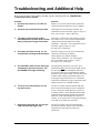
Troubleshooting and Additional Help
Refer to the list below in the unlikely event that you have problems with your TRANSTECH II
Transmission Service System.
Problem:
1. Unit does not power-up, no LEDs are
lighted
Solution:
Polarity is reversed on vehicle battery connection.
Check connection to battery for a loose condition.
2. Unit does not sound the start-up alarm
No fluid/pressure is reaching the machine. See
Transmission Service Procedure, page 4-2 steps a, b,
and c. also see steps 3 and 4 of this page.
3. The start-up alarm sounds, and an
intermittent alarm sounds 30-40 seconds
after pressing the Change Fluid button.
Fluid flow is extrmely slow, but enough to pressure
the system to 4 psi.. service ports are opened when
Change Fluid is pressed and pressure drops
completely. Verify flow. See Transmission Service
Procedure, page 4-2 steps a, b, and c.
See steps 2 & 4, of this page.
4. Unit stops and alarm sounds 30 - 40
seconds after pressing the Drain button
No fluid is being received in unit’s WASTE tank,
Check hose connections to adapters
Check adapters for a kinked condition.
Check vehicle’s fluid flow. See: Transmission
Service procedure, page 4-2 steps a, b and c.
See stepa 2 and 3 of this page.
5. An intermittent alarm sounds during the
Transmission Service Procedure, and
the ENGINE STOP light is flashing.
The transmission fluid level is low 2 qts. press
STOP button Once, this will stop the alarm, but not
the unit’s pump. Check transmission fluid level,
stop engine if fluid is low enough that the dipstick
does not reach to measure fluid. The unit will sound
an alarm when fluid has reached the proper level,
start engine and proceed with service. Check hose
conncetions to adapters for proper connection, check
adapters and hoses for a kinked condition.
6. The level in the transmission is 2 qts.
low after service.
The low level switch from the WASTE tank may
have become disconnected previous to starting the
service. Insert unit’s Drain Hose into a waste oil
recycling container. Press DRAIN WASTE button.
Verify that the pump stops automatically and that
fluid level is still visible though the visual level
window. If not, remove unit’s back panel and check
waste tank level switch wire connctions.
7. New fluid is above the 2qt. line, but the
LOW CLEAN FLUID light is ON.
The low level switch on the new fluid tank has
become disconnected. Remove unit’s back panel
and check the clean tank level switch wire
connections.
5-1
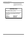
Troubleshooting and Additional Help
8. The unit performs poorly.
Check all hoses and wires for cuts or frays.
Check cabinet for dents or impact markings.
Verify that the filter screen has recently been
cleaned. (Refer to the maintenance log in
Appendix A to view dates of services performed.)
ADDITIONAL HELP
Please verify that items 1-6 above have been reviewed
before calling for additional assistance.
In the unlikely event that problems persist with the unit call
Technical Support, have your model and serial numbers
available before you call. Remember to send in your
warranty card.
in the U.S.
(714) 558-4822
(800) 288-3161
5-2
INTERNATIONAL:
YOUR LOCAL
DISTRIBUTOR
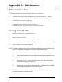
Appendix A - Maintenance
Maintenance Procedures
The following maintenance procedures should be performed on a routine basis:
1.
Carefully clean the exterior with a soft cloth to keep the cabinet looking new. Check the
cabinet for dents or impact markings, if found, inspect for damaged components.
2.
Check all hoses and wires for cuts or frays.
3.
Clean the unit’s filter screens after every 100 services or
6 months, which ever comes first. See the next section for procedure.
Cleaning The Unit’s Filter
1.
Disconnect power harness from any power source.
2.
Remove the unit’s back panel.
3.
Locate the ½” hose leading from the filter (top of either clean tank or waste tankfront lower
corner of the tank) to the bottom fitting of the pump.
4.
Remove the hose from the fitting on the pump.
NOTE: If pump is equipped with a “Press-on” fitting (output side of pump), follow the next
steps. The connection is composed of two parts, a nipple and an elbow.
2.
a)
Press and hold the elbow into the nipple to release the compression ring.
b)
With the elbow pushed in, press the ring into the fitting, then pull elbow out of
the nipple.
c)
Repeat steps a) & b) for hose side (if necessary). Note the section of hose
inserted into the fitting as it is removed.
d)
Install hose in reverse order as it was removed. Verify that the hose is inserted
into the fitting the same distance as the hose removed.
Carefully, press on the hose downward and pull filter away from the tank (filter is composed of
two parts interlocked to each other with tabs).
A-{page11}
Appendix A - Maintenance
3.
Once the filter is separated, pull the hose and filter out of the machine.
4.
Use a fine pick (or a pin bent to a hook configuration), insert it into the filter screen and pull
screen outward. Clean or replace screen as necessary
5.
Assemble in reverse order as removed.
6.
Enter initials, date, and a check mark in the appropriate boxes of the Maintenance Record at
the end of this chapter.
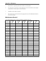
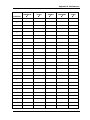
Maintenance Record
Use the following table to keep a record of maintenance performed on the unit.
DRAIN FLUID
TANKS
Initial/Date
/
/
/
/
/
/
/
/
/
/
/
/
/
/
/
/
/
/
/
A-2
.
9
CLEANED
FILTERS
9
CLEAN EXT.
CABINET
9
CHECK HOSES
AND WIRES
9
9
OTHER
Appendix A - Maintenance
DRAIN FLUID
RESERVOIR
Initial/Date
/
9
CLEANED
FILTER
9
CLEAN EXT.
CABINET
9
CHECK HOSES
AND WIRES
9
9
OTHER
/
/
/
/
/
/
/
/
/
/
/
/
/
/
/
/
/
/
/
/
/
/
/
/
/
/
A-3
Appendix B - System Accessories
Standard Adapter Kit
The most commonly used application are listed below; however, other
applications may apply.
Adapter
Number
Qty.
Description
General Application
060-1000
1
¼“ Male end bump tube
Most Asian vehicles
060-1100
1
5/16” Male end bump tube
Most Asian vehicles
060-1200
1
3/8” Male end bump tube
Most Asian vehicles
060-1300
1
¼” Open end hose
Most Asian vehicles
060-1400
1
5/16 Open end hose
Most Asian vehicles
060-1500
1
3/8 Open end hose
Most Asian vehicles
060-1700
1
5/16 Male Flared tube w/nut
Most GM vehicles
060-1800
1
3/8 Male Flared tube w/nut
Most GM. vehicles
060-3800
1
#5 - 45 Flared tube w/nut
European Vehicles w/Bosch
system
060-0450
2
Hose clamp
General application
061-0605
1
Adapter Male nipple #5 X #6
45 - Flared
Use with adapters # 060-3800
& # 062-0140
062-0100
1
5/16 Male deep thread flared
tube w/nut
Ford vehicles
062-0110
1
5/16 Female deep thread flared
seat
Use with adapter # 062-0100
062-0120
1
3/8 Male deep thread flared
tube w/nut
Ford vehicles
062-0130
1
3/8 Female deep flared seat
Use with adapter # 062-0120
062-0140
1
#6- 45 Flared tube w/nut
European vehicles w/Bosch
B-1
Appendix B - System Accessories
systems
062-0170
1
5/16 Female flared seat
Use with adapter # 060-1700
062-0180
1
3/8 Flared female seat
Use with adapter # 060-1800
080-0592
1
Adapter, MQD X ¼ Female
Pipe thread
General application
080-0593
1
Adapter, MQD X ¼ Male
Pipe thread
General application
080-0594
1
Adapter, MQD X 3/8 Female
Pipe thread
General application
080-0595
1
Adapter, MQD X 3/8 Male
Pipe thread
General application
NOTE: Ford vehicles with plastic insert quick connectors; Do not remove the metal tube
from the plastic insert connector.
a. Remove the adapting piece threaded onto the radiator and the metal cooler line.
b. Thread the corresponding adapter according to size (#080-0593 or #080-0595)
c. Connect adapter # 080-0592 or #080-0594 to the cooler line.
OR:
B-2
Use 060-4200 onto radiator (from Deluxe Adapter Kit, if available).
Use 060-1400 & Clamp on cooler line, tighten securely.
Appendix B - System Accessories
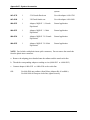
Deluxe Adapter Kit
Adapter
Number
Qty.
Description
General Application
060-1550
1
½” Open end hose
Chrysler V-10 and diesel models
062-2040
1
½ Male tube w/locking shoulder
quick conn.
Chrysler V-10 and diesel models
060-2600
1
16mm X 1.5 Thread pitch
Mercedes Benz
060-2402
060-2740
060-2741
060-2742
2
1
3
1
14 mm.
14 mm.
14 mm.
14 mm.
060-4200
1
5/16 Male tube w/locking
shoulder, quick conn.
Dodge / Ford
060-4300
1
3/8 Male tube w/ locking
shoulder, quick conn.
Dodge
Banjo fitting
Double banjo bolt
Brass washer
Cap nut
Ford Escort
B-3
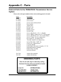
Appendix C - Parts
External Parts for the TRANSTECH Transmission Service
System
Please refer to the part numbers below when ordering parts for the unit.
Part #
010-0027
010-0026
010-6000
010-6001
010-5004
010-5602
010-6060
011-0031
020-8043
020-1600
040-0612
040-0613
040-0623
040-1200
040-2000
040-2200
050-1000
050-3001
060-5810
080-0230
200-8611
200-8612
200-8223
Description
Wheel
Wheel Hub cap
Swivel caster
Swivel caster with break lock
Hose bracket
Adapter Box
Reservoir cap
Handle, steel
Harness, power
Internal Light
Screw, Allen Head, ¼-20 x ½ (Handle)
Screw, Phillips, stainless steel 6-32 (Rear panel)
Screw, Allen Head, 8-32 x 5/8 (Control Panel)
Screw 5/8 php x #6 (for adapter box)
Flat washer #6 (for adapter box)
Threaded Standoff (for adapter box)
Screen filter inline ½ MPT. Pp.
Check valve, (disposal hose)
Cap plug (handle)
Female Quick Disconnect Couplers, 1/4”, Ni
Output/Return hose assembly
Disposal hose assembly
Operators Manual
200-3100
200-3101
Adapter Kit (standard)
Adapter Kit (deluxe)
ORDERING PARTS
Parts for the unit may be ordered by calling
Customer Service, have your model and serial
numbers available:
in the U.S.
(714) 558-4822
(800) 841-8810
INTERNATIONAL:
YOUR LOCAL
DISTRIBUTOR
C-1