1
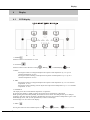
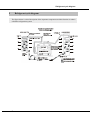
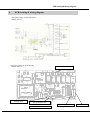
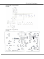
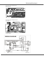
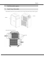
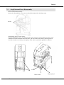
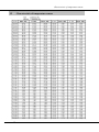
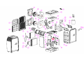
SERVICE MANUAL MOBILE SERIES AMC-15A Content CONTENT 1 1.1 1.2 1.3 2 3 4 4.1 Safety precaution ...................................................................................................................... 1 Installation ............................................................................................................................................. 1 Caution ................................................................................................................................................... 1 Operational ............................................................................................................................................. 1 Specification .............................................................................................................................. 3 Out dimension ........................................................................................................................... 4 Display ....................................................................................................................................... 5 LED display........................................................................................................................................... 5 5 6 7 Refrigerant cycle diagram ....................................................................................................... 7 PCB drawing & wiring diagram ..............................................................................................8 Unit Disassembly sequence..................................................................................................... 11 7.1 Step1 Casing Disassembly ............................................................................................................. 11 7.2 Step2 Internal Parts Disassembly ................................................................................................... 12 8 Exploded .............................................................................................................................................. 13 9 Feature ..................................................................................................................................... 16 9.1 9.2 Parts of the Air Conditioner .............................................................................................................. 16 Accessories......................................................................................................................................... 16 10 Electronic function ................................................................................................................. 17 10.1 10.2 10.3 10.4 10.5 10.6 10.7 10.8 Function ............................................................................................................................................... 17 Controller Specifications ....................................................................................................................... 17 Controller Structure................................................................................................................................ 17 Sensor Definitions. ................................................................................................................................ 17 Mode .................................................................................................................................................... 17 Timer Settimg ...................................................................................................................................... 19 Sleep..................................................................................................................................................... 19 Protection function........................ ...................................................................................................... 19 11 Basic test procedure ................................................................................................................ 21 11.1 11.2 11.3 11.4 Defective compressor .......................................................................................................................... 21 Sealed refrigeration system repairs ...................................................................................................... 22 Fan motor ............................................................................................................................................. 24 Capacitor .............................................................................................................................................. 25 12 Characteristic of temperature sensor.................................................................................... 26 13 Trouble shooting...................................................................................................................... 27 13.1 Trouble shooting problems..................................................................................................................... 28 13.2 Trouble shooting for electrical system................................................................................................... 29 Safety Precaution 1 Safety precaution 1.1 Installation For electrical work, contact the dealer, seller, a qualified electrician, or an Authorized service center. Do not disassemble or repair the product by yourself. Sharp edges could cause injury, be especially careful of the case edges and the fins on the condenser and evaporator. Be sure the installation area does not deteriorate with age. Take care to ensure that power cable could not be pulled out or damaged during operation. Do not place anything on the power cable. Do not plug or unplug the power supply plug during operation. Do not store or use flammable gas or combustible near the product. When flammable gas leaks, turn off the gas and open a window for ventilation before turn the product on. If strange sounds, or small or smoke comes from product. Turn the breaker off or disconnect the power supply cable as soon as possible. When the product is soaked (flooded or submerged), contact an Authorized service center. Be caution that water could not enter the product. Turn the main power off when cleaning or maintaining the product. When the product is not be used for a long time, disconnect the power supply plug or turn off the breaker. 1.2 Caution Always check for gas (refrigerant) leakage after installation or repair of product. Install the drain hose to ensure that water is drained away properly. Keep level even when installing the product. Do not install the product where the noise or hot air for the outdoor could damage the neighborhoods. Use two or more people to lift and transport the product. Do not install the product where it will be exposed to sea wind (salt spray) directly. 1.3 Operational Do not expose the skin directly to cool air for long periods of time. (Do not sit in the draft). Do not use the product for special purposes, such as preserving foods, works of art, etc. It is a consumer air conditioner, not a precision refrigerant system. Do not block the inlet or outlet of air flow. Use a soft cloth to clean. Do not use harsh detergents, solvents, etc. Do not touch the metal parts of the product when removing the air filter. They are very sharp. Do not step on pr put anything on the product. Always insert the filter securely. Clean the filter every two weeks or more often if necessary. Do not insert hands or other object through air inlet or outlet while the product is operated. Do not drink the water drained from the product. 1 Specification Replace the all batteries in the remote control with new ones of the same type. Do not mix old and mew batteries or different types of batteries. Do not recharge or disassemble the batteries. Do not dispose of batteries in a fire. If the liquid from the batteries gets onto your skin or clothes, wash it well with clean water. Do not use the remote of the batteries have leaked. 2 Specification 2 Specification Model Nameplate marking Power supply Cooling Capacity Cooling Power consumption Heating Power consumption Cooling Rated current Cooling SCE System data Refrigerant type Operation pressure Moisture Removal(30℃,RH80%) Indoor air flow (Hi/Mi/Lo) Noise level (Hi/Mi/Lo) Dimension&Weight Dimension (WxHxD) Packing (WxHxD) Net/Gross weight System Details Compressor Model Type Capacity Input Rated current(RLA) Locked rotor Amp(LRA) Thermal protector Capacitor Refrigerant oil Fan Motor Model Input Capacitor Speed(hi/mi/lo) ±50 Evaporator Number of rows Tube pitch(a)x row pitch(b) Fin spacing Fin type (code) tude outside dimension type axial length x height x width Number of circuits Condenser Number of rows Tube pitch(a)x row pitch(b) Fin Fin type (code) tude outside dimension type axial length x height x width Number of circuits The test condition is 35'C db/24'C wb 3 AMC-15A Ph-V-Hz W W W A W/W 1φ,220V~240V,50Hz 4400 1700 1500 7.5 2.61 g Mpa L/DAY m³/h dB(A) R410A/605g 5.5 70 420/380/350 56/53/50 mm mm kg 300x505x778 330x550x815 28.5/30.5 W W A A CC W Rpm mm FPI mm mm FPI mm mm 44A293J-FEKC Rotary 3349W±5% 1220W±5% 5.9A±5% 27.4A±5% B220-150*-141C 30uF 450VAC 270 Inner Motor 78-3-AL 100/90/81 3uF 1100/1000/900 3 21x19.7 18 Hydrophilic aluminum Ф7 inner groove tube 298x273x38.1 2 4 21x19.7 18 aluminum Ф7 inner groove tube 347x336x38.1 2 Outer Motor 71-3-AL 114 3.5uF 1100 Out dimension 3 Out dimension 4 Display 4 Display 4.1 LED display 1. POWER Press this button to switch the unit on or off 2. FUNCTION Press this button to select between Cooling ( ), Heating ( ) or Dehumidifying ( ) mode 3.TEMP+ Pressing this button in cooling mode adjusts the required room temperature by 1°C up to a maximum temperature of 30°C. Pressing this button in heating mode adjusts the required room temperature by 1°C up to a maximum temperature of 25°C. 4. TEMP Pressing this button in cooling mode adjusts the required room temperature by 1°C to a minimum temperature of 17°C. Pressing this button in heating function adjusts the required room temperature by 1°C to a minimum temperature of 15°C 5. LED-DISPLAY The display shows the current ambient temperature in operation. By pressing the [TEMP+] or [TEMP-] buttons, the required target temperature is displayed. When pressing the timer button [TIMER], the number of hours is shown until delayed start up or delayed shutdown. After each setting, the display automatically shows the current ambient temperature again. In the dehumidifying mode, “dH” (or “HP” upside-down) is shown on the display. Error messages are also shown in the display. 6. SPEED Pressing this button sets the ventilation speed to “ 5 (low)”, “ (medium)”, “ (high)” or “AUTO Display (Automatic)”. If “AUTO” is selected, the ventilator operates at temperature differences larger than 9 degrees at top speed. If the temperature reduces to a difference smaller than 4 degrees, the ventilator switches to middle blower position. If the temperature reduces further until the target temperature, the ventilator switches to the lowest blower position. 7. TIMER Programmable timer button for delayed start up or delayed shutdown How to program a delayed start up This function is used to set the number of hours delay before the appliance comes on. Proceed as follows: Press [TIMER] button in Stand-by mode (unit is plugged in but not in operation, no display on the panel), to set the number of hours delay before the appliance comes on. Select the required function (cooling, heating, and dehumidification), wait until the unit displays the ambient temperature, and then set the desired temperature. After the set number of hours has expired, the unit starts automatically. If you press the [POWER] button before the time has expired, the delayed start up will be cancelled, the unit turns on and can be operated in the required operating mode. How to program a delayed shutdown This function is used to set the number of hours delay before the appliance goes off. Proceed as follows: Start the unit in required function (cooling, heating or dehumidifying) Press the [TIMER] button during operation and enter the required number of hours delay before the appliance goes off. After the flashing of the number of hours on the LED has stopped, can select the required temperature. After the set number of hours has expired, the unit shuts down automatically. If you press the [POWER] button before the time has expired, the unit shuts down. 8. SLEEP This function is ideal for the night as it gradually reduces operation of the appliance. The sleep function maintains the room at optimum temperature and with silent operation. When you use the sleep function, first set the timer as described in the functions. Delayed start and delayed shutdown: Press the [TIMER] button until the required hours appear on the display. After the hour display, the display switches automatically to the previous set temperature display. To change the temperature, press the [TEMP+] or [TEMP-] buttons. With each press on the button, the temperature increases or decreases by 1°C. 6 Refrigerant cycle diagram 5 Refrigerant cycle diagram The figure below is a brief description of the important components and their function in what is called the refrigeration system 7 PCB drawing & Wiring diagram 6 PCB drawing & wiring diagram The below picture is PCB schematic: 800161-0Y-4-5 The below picture is PCB Drawing 800161-0Y-4-5 Water full switch Inner Motor Switch Inner Tempreature Sensor 10 pin plug OuterTempreature Sensor 8 Display PCB drawing & Wiring diagram The below picture is Display schematic: 800145-BY-1 The below picture is Display Drawing: 800145-BY-1 9 PCB drawing & Wiring diagram The below picture is PCB Layout: 800161-0Y-4-5 The below picture is Display Layout: 800145-BY-1 Wiring Diagram 10 Feature 7 Unit Disassembly sequence 7.1 Step1 Casing Disassembly disassemble hot and cool air louver and unscrew the casing of front panel,side panel and top panel screws screws disassemble Filter and unscrew screws 11 Feature 7.2 Step2 Internal Parts Disassembly Motor and PCB Disassembly: please also dismantle the screws at two sides,for the right side is the fasten strip screws Disassembly steps for water motor : please dismantle the screws of condensor,slide up the partition panel.and then slow take out the condensor from the left hand side.From there, you can see the water motor.Caution, please be note that in order to avoid any water split by water wheel, you should uphold the condensor screws Water motor 12 Water wheel Characteristic of temperature sensor 12 Characteristic of temperature sensor 25 Electronic function 10 Electronic function 10.1 Function 10.1.1 Cooling , Heating or Dehumidifying mode 10.1.2 With Auto switch on, off and sleep mode function 10.1.3 Ts range:Cooling:17~30℃/65~90°F;Heating:15~25℃/60~80°F; Time delay safety control 10.1.4 With 3 fan speed mode available in high, medium, low for the upper fan system while for the lower fan system is only available with single speed. This single fan speed is working together with the compressor and can auto detect the any damages within 10.2 Controller Specifications 10.2.1 Normal power source: 220VAC±15%或 110VAC±15% 10.2.2 Operation temperature for electrical system working temperature range:-10℃~+60℃ storage temperature range:-20℃~+70℃ relative humidity range:35~98% 10.2.3 temperature sensor:R25/50=5K、B=3470 temperature precision:±1℃ 10.2.4 display ambient temperature 10.2.5 For Fahrenheit switching, please press function key for 10 s during the stand by mode. 10.3 Controller Structure The control systems are consist of remote control, internal control display, main PCB board, and internal receiver. While for internal PCB board output systems are consists of upper fan system (high, medium and low) and compressor 10.4 Sensor Definitions TA: Temperature of ambient, (T1). TE: Temperature of evaporator, (T2). TS: Setting temperature, (T3). 10.5 Mode 10.5.1Cooling 10.5.1.1 In cooling mode,set point temperature 17~30℃/60~90°F;starting temperature is 25℃ (77°F) 。 10.5.1.2cooling mode compressor working condition: 16 Electronic function A: Under the condition of T1≥T +1℃(2°F),compressor will be running B:Under the condition of T1≤T +1℃(2°F),the unit will be switched off,compressor will be off too C:Under the condition of T1≤T +1℃(2°F),the compressor and internal motor system will be switching back to the original setting Note: When compressor is off, cooling operation light is splashing(0.5second per time)When the compressor is running, the operation light will be turned on 10.5.1.3 During the cooling mode, the upper fan system can be set into auto,high,medium,low and auto fan mode High Medium Low internal ambient temperature℃(°F) set point temperature 2(3) 4(6) 10.5.1.4 Cooling mode,lower fan system is working together with compressor 10.5.2 Dehumidification mode( DH display) 10.5.2.1Upper fan system is operated in low fan. Lower fan is working together with the compressor 10.5.2.2 Dehumidification mode. A. Indoor temperature≤0℃,compressor will be off B.0℃<indoor temperature≤20℃,compressor will be on for 15 min and stop for 3 min C.indoor temperature>20℃compressor will be on for 30 min and stop for 3 min We only can check the indoor temperature after such operation finishes after every week, Note: When compressor is stop, the dehumidification indication light is on. 10.5.3Heating mode 10.5.3.1Heating mode: set point temperature range is 15~25℃(60~80°F),starting temperature is 20℃(68°F) 10.5.3.2 Heating mode, compressor working condition A. Under the condition of T3-T1≥+1℃(2°F)compressor will be turned on 17 Electronic function B. Under the condition of T3-T1≤-1℃(2°F)compressor will be turned off C. Under the condition of T1=T3-1℃(2°F)compressor will be operated under the original setting mode Note: Under the condition of compressor off. Heating light is splashing (0.5second per time) compressor will be running and heating indication light will be turned on. 10.5.4 Heating mode, upper fan system is operated in high speed without setting. Lower fan system is working together with compressor 10.6 Timer Setting 10.6.1 Tiner setting can be set 1-24 hours 10.6.2 During the unit operation, you can set numbers of hours.The unit will be auto switch off .While the unit will be auto switch on if the unit is set in auto mode 10.7 Sleep 10.7.1 To set the sleep mode under the cooling setting, To increase this setting press the "UP" button and for each press, the temperature will be increased by 1℃, continually, the temperature will be rise up to 2℃ after the 2 hours operation.Apart from this, the temperature will not be rise up anymore. 10.7.2 To set the sleep mode under the heating setting, To increase this setting press the "down" button and for each press, the temperature will be decreased by 1℃, continually, the temperature will be decrease to 2℃ after the 2 hours operation. Apart from this, the temperature will not be rise up anymore. 10.7.3 It is confirmed that there is no sleep mode function during the dehumidification function 10.7.4 Under this sleep mode, the fan speed remained as low speed 10.8 Protection function 10.8.1 Compressor delay protection 10.8.1.1 When the unit is in operation, compressor need 3 min and 30s for starting 10.8.1.2 When compressor is off and restart again, restarting period is 3 min and 30s 10.8.2 Defrosting protection mode( display DF) Compressor keep on working for 15 min.please check the fan coil temperature ≤1℃.thus compressor will be turned off.if the compressor stop for 3 min&30s.Indoor fan coil temperature >2℃ compressor will be turned on and defrosting mode will be off 10.8.3 Water full protection (display E4) When the water power is closed for 3 seconds, followed by water full protection, control 18 Electronic function system will be off. All the power will be off. Signal will be turn into E4. If the water full signal is off., the control system has to be pressed on or off to restart the operation 10.8.4 E1:indicate the indoor temperature hot and resistance is in error thus control system will be off. 10.8.5 E2:indicate the indoor temperature hot and resistance is in error thus control system will be off. 10.8.6 Refrigerent leaking protection display as E3 Compressor turn on, if the tolerance is ≤5℃ at between indoor temperature and fan coil after operation for 15 min.The compressor will be turn off, and upper fan system will be running at the set speed.The signal display E3 and press the power key or power off to clear this signal. 19 Basic test procedure 11 Basic test procedure 11.1 Defective compressor Compressors are single phase, 115 or 120 volt, depending on the model unit. All compressor motors are permanent split capacitor type using only a running capacitor across the start and run terminal. All compressors are internally spring mounted and externally mounted on rubber isolators. 11.1.1 Compressor wiring test Remove compressor terminal box cover and disconnect wires from terminals. Using an ohmmeter, check continuity across the following: Terminal "C" and "S" - no continuity - Open winding - replace compressor. Terminal "C" and "R" - no continuity - Open winding - replace compressor. Terminal "R" and "S" - no continuity - Open winding - replace compressor. 11.1.2 Ground test Use an ohmmeter set on its highest scale. Touch one lead to the compressor body (clean point of contact as a good connection is a must) and the other probe in turn to each compressor terminal (see Figure 2.) If a reading is obtained, the compressor is grounded and must be replaced. 11.1.3 Checking the compressor efficiency The reason for compressor inefficiency is normally due to broken or damaged suction and/or discharge valves, reducing the ability of the compressor to pump refrigerant gas. This condition can be checked as follows: 1. Install a piercing valve on the suction and discharge or liquid process tube. 2. Attach gauges to the high and low sides of the system. 3. Start the system and run a “cooling or heating performance test.” 20 Basic test procedure If test shows: A. Below normal high side pressure. B. Above normal low side pressure. C. Low temperature difference across coil. The compressor valves are faulty - replace the compressor. 11.1.4 Terminal overload (external) Some compressors are equipped with an external overload which is located in the compressor terminal box adjacent to the compressor body The overload is wired in series with the common motor terminal. The overload senses both major amperage and compressor temperature. High motor temperature or amperage heats the disc causing it to open and break the circuit to the common motor terminal. Heat generated within the compressor shell is usually due to: 1. High amperage. 2. Low refrigerant charge. 3. Frequent recycling. 4. Dirty condenser. 11.1.5 Terminal overload (internal) Some model compressors are equipped with an internal overload. The overload is embedded in the motor windings to sense the winding temperature and/or current draw. The overload is connected in series with the common motor terminal. Should the internal temperature and/or current draw become excessive; the contacts in the overload will open, turning off the compressor? The overload will automatically reset, but may require several hours before the heat is dissipated. 11.1.6 Checking the internal overload 1. With no power to unit, remove the leads from the compressor terminals. 2. Using an ohmmeter, test continuity between terminals C-S and C-R. If not continuous, the compressor overload is open and the compressor must be replaced. 11.2 Sealed refrigeration system repairs 11.2.1 Equipment require 1. Voltmeter 2. Ammeter 3. Ohmmeter 4. E.P.A. Approved Refrigerant Recovery System. 21 Basic test procedure 5. Vacuum Pump (capable of 200 microns or less vacuum.) 6. Acetylene Welder 7. Electronic Halogen Leak Detector (G.E. Type H-6 or equivalent.) 8. Accurate refrigerant charge measuring device such as: a. Balance Scales - 1/2 oz. accuracy b. Charging Board - 1/2 oz. accuracy 9. High Pressure Gauge - (0 - 400 lbs.) 10. Low Pressure Gauge - (30 - 150 lbs.) 11. Vacuum Gauge - (0 - 1000 microns) 11.2.2 Equipment must be capable of: 1. Recovery CFC's as low as 5%. 2. Evacuation from both the high side and low side of the system simultaneously. 3. Introducing refrigerant charge into high side of the system. 4. Accurately weighing the refrigerant charge actually introduced into the system. 5. Facilities for flowing nitrogen through refrigeration tubing during all brazing processes. 11.2.3 Hermetic compressor replacement. The following procedure applies when replacing components in the sealed refrigeration circuit or repairing refrigerant leaks. (Include Compressor, condenser, evaporator, capillary tube, refrigerant leaks, etc.) 1. Recover the refrigerant from the system at the process tube located on the high side of the system by installing a line tap on the process tube. Apply gauge from process tube to EPA approved gauges from process tube to EPA approved recovery system. Recover CFCs in system to at least 5%. 2. Cut the process tube below pinch off on the suction side of the compressor. 3. Connect the line from the nitrogen tank to the suction process tube. 4. Drift dry nitrogen through the system and unsolder the more distant connection first. (Filter drier, high side process tube, etc.) 5. Replace inoperative component, and always install a new filter drier. Drift dry nitrogen through the system when making these connections. 6. Pressurize system to 30 PSIG with proper refrigerant and boost refrigerant pressure to 150 PSIG with dry nitrogen. 7. Leak test complete system with electric halogen leak detector, correcting any leaks found. 8. Reduce the system to zero gauge pressure. 9. Connect vacuum pump to high side and low side of system with deep vacuum hoses, or copper tubing. (Do not use regular hoses.) 10. Evacuate system to maximum absolute holding pressure of 200 microns or less. NOTE: This process can be speeded up by use of heat lamps, or by breaking the vacuum with refrigerant or dry nitrogen at 5,000 microns. Pressure system to 5 PSIG and leave in system a minimum of 10 minutes. Recover refrigerant, and proceed with evacuation of a pressure of 200 microns or a minimum of 10%. 11. Break vacuum by charging system from the high side with the correct amount of refrigerant specified. This will prevent boiling the oil out of the crankcase. NOTE: If the entire charge will not enter the high side, allow the remainder to enter the low side in 22 Basic test procedure small increments while operating the unit. 12. Restart unit several times after allowing pressures to stabilize. Pinch off process tubes, cut and solder the ends. Remove pinch off tool, and leak check the process tube ends. 11.2.4 Special procedure in the case of compressor motor burnout. 1. Recover all refrigerant and oil from the system. 2. Remove compressor, capillary tube and filter drier from the system. 3. Flush evaporator condenser and all connecting tubing with dry nitrogen or equivalent, to remove all contamination from system. Inspect suction and discharge line for carbon deposits. Remove and clean if necessary. 4. Reassemble the system, including new drier strainer and capillary tube. 5. Proceed with processing as outlined under hermetic component replacement. 11.2.5 Rotary compressor special troubleshooting and service Basically, troubleshooting and servicing rotary compressors is the same as on the reciprocating compressor with only a few exceptions. 1. Because of the spinning motion of the rotary, the mounts are critical. If vibration is present, check the mounts carefully. 2. The electrical terminals on the rotary are in a different order than the reciprocating compressors. The terminal markings are on the cover gasket. Use your wiring diagram to insure correct connections. 11.2.6 Refrigerant charge 1. The refrigerant charge is extremely critical. It must be measured charge carefully - as exact as possible to the nameplate charge. 2. The correct method for charging the rotary is to introduce liquid refrigerant into the high side of the system with the unit off. Then start compressor and enter the balance of the charge, gas only, into the low side. The introduction of liquid into the low side, without the use of a capillary tube, will cause damage to the discharge valve of the rotary compressor. NOTE: All inoperative compressors returned to Friedrich must have all lines properly plugged with the plugs from the replacement compressor. 11.3 Fan motor A single phase permanent split capacitor motor is used to drive the evaporator blower and condenser fan. A self-resetting overload is located inside the motor to protect against high temperature and high amperage conditions. 11.3.1 Fan motor test 1. Determine that capacitor is serviceable. 2. Disconnect fan motor wires from fan speed switch or system switch. 3. Apply "live" test cord probes on black wire and common terminal of capacitor. Motor should run at high speed. 23 Basic test procedure 4. Apply "live" test cord probes on red wire and common terminal of capacitor. Motor should run at low speed. 5. Apply "live" test cord probes on each of the remaining wires from the speed switch or system switch to test intermediate speeds. 11.4 Capacitor A run capacitor is wired across the auxiliary and main winding of a single phase permanent split capacitor motor such as the compressor and fan motor. A single capacitor can be used for each motor or a dual rated capacitor can be used for both. The capacitor's primary function is to reduce the line current while greatly improving the torque characteristics of a motor. The capacitor also reduces the line current to the motor by improving the power factor of the load. Run capacitor hook-up line side of the capacitor is marked with a red dot and is wired to the line side of the circuit 11.4.1 Capacitor test 1. Remove capacitor from unit. 2. Check for visual damage such as bulges, cracks, or leaks. 3. For dual rated, apply an ohmmeter lead to common (C) terminal and the other probe to the compressor (HERM) terminal. A satisfactory capacitor will cause a deflection on the pointer, and then gradually move back to infinity. 4. Reverse the leads of the probe and momentarily touch the capacitor terminals. The deflection of the pointer should be two times that of the first check if the capacitor is good. 5. Repeat steps 3 and 4 to check fan motor capacitor. NOTE: A shorted capacitor will indicate a low resistance and the pointer will move to the "0" end of the scale and remain there as long as the probes are connected. An open capacitor will show no movement of the pointer when placed across the terminals of the capacitor. 24 Characteristic of temperature sensor 12 Characteristic of temperature sensor 25 Trouble shooting 13 Trouble shooting PROBLEM No power display on panel or any one of the buttons failure. Remote control failure. Fan motor runs intermittently Compressor stops instantly after startup. POSSIBLE CAUSE Power failure Transformer (Discharge transformer before testing) Display board or main PCB failure Battery failure Cycles on overload. Refrigerant Compressor No power Water alarm Power supply cord Transformer (Discharge transformer before testing) Fan motor will not run. Wire disconnected or connection loose Main PCB failure Capacitor (Discharge capacitor before testing) Will not rotate Fan blower Fan motor noise. Loose screws Worn bearings Compressor will not run while fan motor runs. Voltage Wiring Main PCB failure Capacitor (Discharge capacitor before testing) 26 REMEDY Check the power supplier if the power supplier is supplied to the unit. Check the power cord and correct if damaged. Check resistance between the two input/output lines on transformer. Replace the transformer if either of the input/output is open or the transformer is damaged. Check the voltage on display board. Replace the display board if it is +5V else replace the main PCB. Check the voltage of battery. Replace batteries if the voltage is lower than 2.3V. Check voltage. Call an electrician if not within limits. Test capacitor. Replace if not within +/-10% of manufacture's rating. Check bearings. Replace the motor if the blower wheel cannot rotate freely. Pay attention to any change from high speed to low speed. Replace the motor if the speed does not change. The amount of the refrigerant is too much, making the compressor load too big. Recycle and recharge the refrigerant after checking for the reason. The compressor is blocked inside. Replace after checking for the reason. Check voltage at electrical outlet. Correct if none. Check and correct if water alarm happens. Check voltage at the power cord terminal on Main PCB. Replace the power cord if none. Check resistance between the two input/output lines on transformer. Replace the transformer if either of the input/output is open or the transformer is damaged. Connect wire. Refer to wiring diagram for terminal identification. Repair or replace loose terminal. Select fan speed and Check the voltage on main PCB. Replace the main PCB if no voltage in anyone. Test capacitor. Replace if not within +/-10% of manufacture's rating. Replace if shorted, open or damaged. Fan blower hitting scroll. Realign assembly. Check fan motor bearings. Replace the motor if motor shaft do not rotate. Replace the fan blower if cracked, out of balance, or partially missing. Tighten them. Replace the motor if knocking sounds continue when running or loose, or the motor hums or noise appears to be internal while running. Check voltage. Call Supply Authority if not within limits. Check the wire connections, if loose, repair or replace the terminal. If wires are off, refer to wiring diagram for identification, and replace. Check wire locations. If not per wiring diagram, correct. Check voltage of main PCB. Replace the main PCB if open. Check the capacitor. Replace if not within +/-10% of manufacturers rating. Replace if shorted, open, or damaged. Trouble shooting Water tank full Check the temperature setting if not at the coolest (in cooling mode) or the warmest (in heating mode). Set it if not. Check the compressor for open circuit or ground. If open or grounded, replace the compressor. Remove the cabinet and carefully rearrange tubing not to contact cabinet, compressor, shroud and barrier. Check and pour if the water tank is full. Water depth sensor if failure Check and replace if failure. Water depth is over load in chassis Water depth sensing structure Air filter Check and drainage the water in the chassis by open the drainage hose on the chassis. Room temp sensor Compressor Excessive noise. Water full alarm Copper tubing Air discharge pipe Unit undersized Condenser and Evaporator Circulation in condensing water Fan motor Cooling or heating feels not good Air flow Less refrigerant Capillary tube Compressor Heat sources No power Wiring Temperature setting Mode setting No cooling or heating. Compressor Electric heater failure Over heat fuse failure Main PCB Power supply The unit starts and stops frequently. Main PCB Room temperature Sudden change of temperature units from °C to °F and vice versa 27 Check and replace or realign if the structure is failure. Clean or replace if restricted. Realign and assemble if the installation of the air discharging pipe failure. Replace if damaged. Determine if the unit is properly sized for the area to be cooled or heated. Clean or replace if restricted. To check wether water motor damaged or water hose is block or not Check the fan capacitor and replace if not within +/-10% of manufactures rating. Clean or remove if any barrier is found to block the inlet/outlet wind flow of the unit. Check the tubes for reasons of leakage. Recycle the refrigerant, correct the leakage points and recharge. Regulate the flow if capillary tube and make the evaporating temperature appropriate if the evaporator is frosted. Replace if blocked. Repair joint if leaking. The inlet and outlet valve of the compressor is damaged, making the low pressure connected with the high pressure. The refrigerating system can not produce high pressure and low pressure. Replace the compressor after checking for the reason. Reduce if too many. Check the voltage. Call an electrician if no within the limit. Check the terminals. Repair and correct if loose. Check and adjust the temperature setting. Check and adjust the mode setting. Check and replace if the compressor, the over-load protector or wiring is broken. Check and replace if the heater is damaged. Check and replace if the fuse is damaged. Check the voltage of main PCB. Replace the main PCB when the unit failure in heating mode. The input power supply voltage is too low. Call an electrician if not within limits. Check and replace the main PCB if the compressor relay on PCB is shorted or damaged. When the room temperature is too high, the compressor will protect. Solution: switching the units from °F to °C and viceversa Procedure: Please switch off the unit to “STAND-BY” mode by pressing the button “POWER” on the unit (the unit is plugged in), hold for 5-10 seconds button “FUNC” on the unit and after a beep sound switch on the unit by button “POWER”. Trouble shooting Trouble shooting problems YES YES no signal YES Power cord damged Check main pCB YES Repair and replacement Check if water full or not YES Water drainage Power source proble no Replace no Water full light on no Power on found out with Abnormal Control Abnormal dipslay YES no YES Connection problem between ok YES Micro switch problem Water full after running YES no no Replace micro switch Water pump damaged YES Checking wiring YES Check electrical wiring no Main PCB damage no Connetion being good YES Repair and replacement YES Water wheel problem YES Trouble shooting finish 28 Water pump damaged replacement Trouble shooting Trouble shooting for electrical system no unit not running With E1 signal compressor off yes Power source no With E1 signal compressor off yes Power source 120V Sensor wire off yes yes Fan coil damaged Plug in no Fuse damaged Checking fuse no replac ement Transformer 12V Transformer damaged replac ement no Damage in diode replac ement yes 7805 damaged replac ement Main PCB daagemd OK no yes Replacing fuse 7805 13V input rate Replacing fuse 78055V output no PCB damaged yes no Electrical wiring back to normal 29 Plug in no Senor of fan coil damaged Temperature sensor damaged Transformer 120V yes replacement PARTS GUIDE MOBILE SERIES AMC-15A Exploded view of model AMC-15A No 1 2 3 4 5 6 7 8 9 10 11 12 13 14 15 16 17 18 19 20 21 22 23 24 25 26 27 28 29 30 31 32 33 34 35 36 37 38 39 40 41 42 43 44 45 46 47 48 49 50 51 52 53 54 55 56 Description Part Code MODEL: AMC-15A PACKING BOTTOM PSF WHEEL TWP BASE RUBBER STOPPER COMP, 44A293AJ-FEKC PARTITION FRONT PANEL UPPER COVER-FRONT (COLD AIR) OUTLET FOR COLD AIR STRAINER CAPILLARY 1.0x2.2xL500 CAPILLARY, 1.0x2.2xL550 DISCHARGE TUBE CONDENSER SUCTION TUBE EVAPORATOR Horizontal blade Join for horizontal blade LEFT SIDE PLATE COND FILTER EVA FILTER HOUSING BLOWER,LEFT BOTTOM WHEEL BLOWER φ215x95 ABS+GF HOUSING BLOWER,RIGHT BOTTOM HOUSING BLOWER,LEFT TOP WHEEL BLOWER φ215x95 ABS HOUSING BLOWER,RIGHT TOP CAP, 3.0uFx450VAC CAP, 3.5uF 450V MOTOR BRACKET OUTER MOTOR INNER MOTOR DISPLAY PCB CONTROL PANEL PACKING TOP PSF MAIN PCB Clip for capacitor CAPACITOR,30uF 450VAC OUTLET FOR HOT AIR,RIGHT OUTLET FOR HOT AIR,LEFT UPPER COVER-BACK (HOT AIR) PIPE OUTER ,Φ150mm PIPE EXHAUST, φ150mm OUTLET FOR HOT AIR WHEEL WATER COVER FOR WATER MOTOR WATER MOTOR , 230V/50Hz SWITCH, KW3A-16ZA2-C075 16A FLOATER wire holder-bottom MAIN BRACKET RIGHT SIDE PLATE Back PANEL REMOTE CONTROLLER Control panel receiver 400MM Cover top POWER CORD CARTON PVC transparent tube xΦ19xL600 410284-0Y-1 290025-00XY-H 210523-BY-1 310025-0Y-1 700167-00-1 210524-FY-1 210574-0Y-1-H-2 210575-0Y-1-H 210578-0Y-4-H 740007-30XY 780203-0Y-14 780203-0Y-37 780222-BY-4 710156-CY-3 780223-0Y-7 710157-0Y-4 210534-0Y-3-H 210580-0Y-3-H 210527-AY-1-H 210533-AY-12-H 210532-AY-12-H 410330-0Y-1 210631-0Y-2 410331-0Y-1 410254-0Y-1-X 210631-0Y-1 410253-AY-1-X 730049-00XY 730052-0Y-1 110276-0Y-1 720071-0Y-3-AL 720078-0Y-3-AL 800145-BY-1-Q 210577-0Y-1-H 410283-0Y-1 800161-0Y-4-5-Q 190004-0B4Y 730002-20XY 210537-AY-1 210536-BY-1 210576-0Y-1-H 210581-0Y-2 290008-A0XY 210579-0Y-4-H 210186-0BAY 210538-AY-1 720075-BY-3 750035-0Y-1 220001104Y 210467-AY-3 110196-AY-1 210526-AY-1-H 210574-0Y-1-H-2 800032-0Y-32-K 800180-0Y-1-A 310029-0Y-1 760043-0Y-3-1 610077-0Y-11 230007-80XY Note Price Code AH AC AU AB BM AL AK AG AF AL AR AR AG BL AK BK AC AC AH AH AH AP AN AP AP AM AP AE AE AH BA AZ AS AL AH AX AB AP AF AF AG AD AN AG AL AD AX AL AC AC AD AH AH AT AK AB AF AL AB


![AMB manual(Standard Remote)-20101214[1]](http://vs1.manualzilla.com/store/data/006732774_1-b3f78677e1b6c8132d48ca231775dd9a-150x150.png)