1
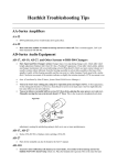
INSTALLATION
INFORMER L.E.D. FUEL & BATTERY GAUGE
CUSTOMER SERVICE
PARTS INCLUDED
1
1
Informer L.E.D. Fuel and Battery Gauge
Hardware/Wiring Kit Including:
1
‘08 and Up Adapter Disc—RED
1
‘07 and Earlier Adapter Disc—GREEN
1
2 Pin Black Amp Connector
1
4 Pin Black Amp Connector
4
#6-32 Stainless Steel Hex Nuts
4
#6 External Tooth Lock Washers
1
Installation Instructions
Please read and understand entire instructions before starting installation.
THANK YOU FOR CHOOSING KϋRYAKYN!
IN ORDER TO PROTECT YOU AND OTHERS FROM POSSIBLE INJURY AND/OR
PROPERTY DAMAGE OR LOSS, PLEASE PAY CLOSE ATTENTION TO ALL
INSTRUCTIONS, WARNINGS, CAUTIONS AND NOTICES REGARDING THE USE
AND CARE OF THIS PRODUCT.
THIS INDICATION ALERTS YOU TO THE FACT THAT
IGNORING THE CONTENTS DESCRIBED HEREIN CAN
RESULT IN POTENTIAL DEATH OR SERIOUS INJURY.
This indication alerts you to the fact that ignoring the
contents described herein may negatively affect product
performance and functionality.
This indication alerts you to the fact that ignoring
the contents described herein can result in potential
injury.
IF INSTALLING THIS PRODUCT FOR ANOTHER PARTY,
PLEASE MAKE SURE THEY RECEIVE THIS COPY OF THE
INSTALLATION INSTRUCTIONS SO THEY ARE AWARE OF
THE IMPORTANT INFORMATION CONTAINED IN THEM.
TOOLS SUGGESTED
Needle Nose Pliers, Socket Set and Ratchet, Set of Combination Wrenches, Factory Service
Manual for Reference, Electrical Tape, Bright Flashlight
STRICTLY OBSERVE THE FOLLOWING GUIDELINES IN ORDER TO USE THE
PRODUCT PROPERLY AND AVOID POTENTIALLY DANGEROUS ACCIDENTS.
STEP 1
Read and understand all steps in the instructions before starting the
installation. Park the motorcycle on a hard, level surface and turn off the
ignition. Let cool.
READ AND UNDERSTAND ALL THE INSTRUCTIONS BEFORE
PROCEEDING. FAILURE TO FOLLOW THESE INSTRUCTIONS
COULD RESULT IN DAMAGE TO THE MOTORCYCLE AND/OR
INJURY OR DEATH TO THE RIDER OR INSTALLER.
KÜRYAKYN RECOMMENDS THIS INSTALLATION BE
PERFORMED BY AN EXPERIENCED MECHANIC. IF YOU ARE
NOT COMPLETELY CONFIDENT IN YOUR MECHANICAL
SKILLS, HAVE THIS GAUGE INSTALLED BY A
PROFESSIONAL, EXPERIENCED MECHANIC.
7282-22HD-0812
-cont.-
7282
877.370.3604 (toll free)
INSTALLATION QUESTIONS
[email protected]
or call 715.247.2983
LIMITED WARRANTY
Küryakyn warrants that any Küryakyn products
sold hereunder, shall be free of defects in
materials and workmanship for a period of one
(1) year from the date of purchase by the
consumer excepting the following provisions:
● Küryakyn shall have no obligation in the event
the customer is unable to provide a receipt
showing the date the customer purchased the
product(s).
●The product must be properly installed,
maintained and operated under
normal conditions.
●Küryakyn makes no warranty, expressed or
implied, with respect to any gold plated
products.
●Küryakyn shall not be liable for any
consequential and incidental damages, including
labor and paint, resulting from failure of a
Küryakyn product, failure to deliver, delay in
delivery, delivery in nonconforming condition, or
for any breech of contract or duty between
Küryakyn and a customer.
●Küryakyn products are often intended for use in
specific applications. Küryakyn makes no
warranty if a Küryakyn product is used in
applications other than intended.
●Küryakyn electrical products are warranted for
one (1) year from the date of purchase by the
consumer. L.E.D.’S contained in components of
Küryakyn products will be warranted for defects
in materials and workmanship for 3 years from
the date of purchase where as all other
components shall be warranted for one(1) year.
This includes, but is not limited to; control
modules, wiring, chrome & other components.
●Küryakyn makes no warranty of any kind in
regard to other manufacturer¹s products
distributed by Küryakyn. Küryakyn will pass on
all warranties made by the manufacturer and
where possible, will expedite the claim on behalf
of the customer, but ultimately, responsibility for
disposition of the warranty claim lies
with the manufacturer.
ABOUT OUR CATALOG
For purchasing Küryakyn® products, you
can receive a complete catalog free of charge.
Send the Proof-of-Purchase below with
your address to: Küryakyn, P.O. Box 339,
Somerset, WI 54025.
Please indicate either Accessories Catalog for
Harley-Davidson® or GL & Metric Cruisers.
Be sure to ask your local dealer about other
Küryakyn® products, the motorcycle parts and
accessories designed for riders by riders.
©2005 Küryakyn USA® All Rights
reserved.
YOU WILL BE WORKING AROUND THE ENGINE AND EXHAUST SYSTEM
DURING INSTALLATION. ENSURE THAT THE ENGINE AND EXHAUST
SYSTEM HAVE FULLY COOLED TO PREVENT INJURY.
Avoid potential electrical shock! Disconnect the battery before starting this
procedure.
A factory service manual may be helpful in performing this installation. Do not
attempt to perform this installation if you are not confident in your ability to
complete all of the steps in the procedure; consult a trained technician.
INSTALLATION ON ‘88 -’00 MODELS
STEP 2
Disconnect the negative battery lead.
STEP 3
The stock fuel gauge wires run through a tube welded in place inside the gas tank. The wires from
the gauge exit the bottom of the fuel tank through this tube opening. The wires are held in place
with a small clip and lead to an “Amp” connection plug. Gently open this clip and disconnect the
plug - this will provide more free play in the wires easing removal of the gauge. Carefully pull
upward on the original fuel gauge, lifting it from the tank. DO NOT TWIST the gauge — however,
you may rock it slightly side to side.
STEP 4
Unscrew the nut holding the pink OR yellow/white stripe wire connected to the terminal marked
“S” from the stock fuel gauge. READ and remove the warning tag on the “S” terminal of the
Informer fuel gauge. PIC 1 SECURE ONLY THE PINK OR YELLOW/WHITE STRIPE WIRE TO THE “S”
TERMINAL OF THE DECO WITH ONE OF THE #6-32 NUTS AND LOCK WASHERS.
CONNECTING ANY OTHER WIRE TO THIS “S” TERMINAL MAY CAUSE A
FUEL TANK EXPLOSION RESULTING IN SERIOUS INJURY OR DEATH.
STEP 5
NOTE:
Remove the heat shrink from the “G” and “I” terminals of the Informer fuel gauge. Unscrew the
nuts holding the two black wires to the “G” terminal and the orange wire from the
“I” terminal of the stock gauge and remove the wires.
PIC 1
Removing the bulb holder can simplify removal of the “G” terminal wires.
STEP 6
Assemble the two black ground wires to the “G” terminal of the Informer fuel
gauge with one of the provided #6–32 nuts and lock washers.
STEP 7
Assemble the orange wire to the “I” terminal of the Informer fuel gauge with one
of the provided #6–32 nuts and lock washers.
STEP 8
Make sure all nuts are tightened securely.
STEP 9
Carefully push the wires into the fuel gauge mounting hole so they don’t interfere with the
insertion of the new gauge housing. Reconnect the plug disconnected in STEP 3.
STEP 10
Align the new gauge with the key slots in the tank and carefully press the new gauge housing all
the way into the tank-mounting hole until it is flush to the top surface.
STEP 11
Re-connect the battery and turn on the ignition to test the new gauge.
REMOVE AND READ THIS TAG
INSTALLATION ON ‘01-’07 MODELS
STEP 1
Disconnect the battery negative lead.
PAGE
2
-cont.-
INFORMER FUEL AND BATTERY GAUGE
INSTALLATION
STEP 2
Disconnect the Amp style plug connector from the gas gauge wires found beneath the fuel tank.
The fuel gauge side of the Amp connector must be removed to allow the wires
PIC 2
from the stock gauge to be pulled through the wire passage in the fuel tank. This
plug may either be cut off, or the pins may be removed from the plug body
(Consult your service manual in the electrical section - “Amp Multi-lock Electrical
Connectors”) WHATEVER YOU DO , DO NOT cut the wires on the main wiring
harness side of this plug! Remove the stock gas gauge by pulling it straight up,
you may rock it gently from side to side, but DO NOT TWIST! Disconnect any
plug connections under the gauge. Remove the stock gauge and carefully pull the
wiring up through the passage in the tank.
STEP 3
Harley-Davidson has used two different wiring configurations for the fuel gauges
found on 2001-2007 models. For our purposes, we’ll refer to them “3 wire”
and “Banana Jack 4-wire”. The “3-wire” uses three equal length wires; yellow,
orange, and black. The “Banana Jack 4-wire” uses two long wires, orange and
black; and two short wires, yellow and black. We have combined these wiring
configurations on one (GREEN) board. PIC 2 This adapter is labeled “Bullet Wiring
Adapter ’07-Earlier”. Remove the #6-32 nut and warning label from the “S”
terminal and the soft plastic stud protectors from the “T” and “G” terminals on the
bottom side of the Informer gauge. Set the adapter in place; it will rest on the
three #6-32 nuts already in place on the studs. Secure the
KURYAKYN CONNECTOR TYPE
adapter with three #6-32 nuts and star washers supplied.
PIC 3
Yellow
Amp. Connector
TO COMPLETE THE INSTALLATION ON ‘01-’07
MODELS USING “3-WIRE”
Orange
Black
Amp. Connector
Amp. Connector
HARLEY DAVIDSON
Yellow or
Yellow/White Stripe
Orange
Black or Gray
FIG 1
STEP 1
Route all three of the long wires from the gauge through the tank passage in the
same manner the stock wires were run.
STEP 2
Using a little electrical tape, tape the two unused short yellow and black) together
and place them in the gauge opening in the tank. PIC 3 Carefully push the three
long (yellow, orange and black) wires into the gas gauge mounting hole so they
will not interfere with the insertion of the new gauge housing. Align the new gauge
with the key slots in the tank and carefully press the new gauge all the way into
the mounting hole until it is flush with the top surface.
USE CARE TO ENSURE THIS STEP IS DONE CORRECTLY!
PIC 3
USE HEX
NUTS AND
WASHERS ON
THESE THREE
STUDS
STEP 3
Assemble the pin connectors into the plug body so when the Amp connector halves PIC 4
are joined, the wires will be oriented as in FIG.1. The pin connectors should lightly
“click” into place in the plug body when correctly inserted. If the pin does not click
into place in the plug body, remove the pin, turn it upside down and try again. Do
not force the pins into the body—they should click into position easily. If force is
needed, you are inserting the pins the wrong way. Fold the lock tab over the pin
connectors to secure them into the plug body. (For additional information on
assembling this plug, consult your factory service manual’s “Electrical “ section
under “Amp Multi-color Electrical Connectors”.) Plug the two halves of the Amp
connector together and replace the wiring into the retaining clip on the underside
of the tank.
STEP 4
Reconnect the battery and turn the ignition on to test the new gauge for function.
TO COMPLETE THE INSTALLATION ON ‘01-’07 MODELS
USING “BANANA JACK” 4-WIRE
STEP 1
TAPE AND
Cut the long yellow wire on the green circuit board off at the black heat shrink.
THESE
PIC 5 Using a piece of electrical tape, wrap the end of the wire to seal it. Route the STOW
TWO WIRES
long orange and black wires through the tank passage to be assembled into the
FOR THREE
Amp connector body. It is possible that the bikes wiring harness will contain three WIRE BIKES
wires. In this case, there will be no wire from the Informer’s “Banana Jack” four
wire adapter that will mate with this third wire in the Amp connector half on the bike.
PAGE
3
-cont.-
INFORMER FUEL AND BATTERY GAUGE
INSTALLATION
USE CARE TO ENSURE THIS STEP IS DONE CORRECTLY!
STEP 2
STEP 3
PIC 5
Assemble the pin connectors into the plug body so when the Amp connector halves
are joined, the wires will be oriented as in FIG 2. The pin connectors should lightly
“click” into place in the plug body when correctly inserted. If the pin does not click
into place in the plug body, remove the pin, turn it upside down and try again. Do
not force the pins into the body — they should click into position easily. If force is
needed, you are inserting the pins the wrong way. Fold the lock tab over the pin
connectors to secure them into the plug body. (For additional information on
assembling this plug, consult your factory service manual’s “Electrical “ section
under “Amp Multi-color Electrical Connectors”.) Plug the two halves of the Amp
connector together and replace the wiring into the retaining clip on the underside
of the tank (if applicable).
CUT YELLOW WIRE
HERE AND TAPE FOR
BANANNA JACK BIKES
Connect the short yellow and black wires from the Informer Fuel Gauge to their
corresponding wires in the fuel gauge mounting
hole. Carefully push the wires into the fuel gauge
FIG 2
mounting hole so they will not interfere with the
insertion of the new gauge housing. Align the new
KURYAKYN
CONNECTOR TYPE
gauge with the key slots in the tank and carefully
press the new gauge all the way into the mounting Yellow (short)
Banana Connector
hole until it is flush with the top surface. Reconnect
the battery and turn the ignition on to test the new Black (short)
Banana Connector
gauge for function.
Orange
Amp. Connector
Black (long)
Amp. Connector
HARLEY DAVIDSON
Yellow (short) or short
Yellow/White Stripe
Black (short)
Orange
Black or Grey (long)
TO COMPLETE THE INSTALLATION ON ‘08
and LATER MODELS
STEP 1
Remove the #6-32 nut and warning label from the “S” terminal and the soft plastic stud
protectors from the “T” and “G” terminals on the bottom side of the Informer gauge. Set the RED
wiring adapter labeled Terminal Wiring Adapter ‘08-up in place (PIC 6); it will rest on the four
#6-32 nuts already in place on the studs. Secure the adapter with four #6-32 nuts
PIC 6
and star washers supplied.
STEP 2
Route all three of the long wires from the gauge through the tank passage in the
same manner the stock wires were run.
STEP 3
Carefully push the three long (yellow, orange and black) wires into the gas gauge
mounting hole so they will not interfere with the insertion of the new gauge
housing. Align the new gauge with the key slots in the tank and carefully press the
new gauge all the way into the mounting hole until it is flush with the top surface.
USE CARE TO ENSURE THIS STEP IS DONE CORRECTLY!
STEP 4
STEP 5
Assemble the pin connectors into the plug body so when the Amp connector halves
are joined, the wires will be oriented as in FIG 3. The pin connectors should lightly
“click” into place in the plug body when correctly inserted. If the pin does not click
into place in the plug body, remove the pin, turn it upside down and try again. Do
not force the pins into the body—they should click into position
easily. If force is needed, you are inserting the pins the wrong KURYAKYN CONNECTOR TYPE
way. Fold the lock tab over the pin connectors to secure them
into the plug body. (For additional information on assembling
Yellow
Amp. Connector
this plug, consult your factory service manual’s “Electrical “
section under “Amp Multi-color Electrical Connectors”.) Plug
Orange
Amp. Connector
the two halves of the Amp connector together and replace the
Black
Amp. Connector
wiring into the retaining clip on the underside of the tank.
Reconnect the battery and turn the ignition on to test the new
gauge for function.
HARLEY DAVIDSON
Yellow/White
Stripe
Orange or Blue
Black or Black/
Green Stripe
FIG 3
PAGE
4
-cont.-
INFORMER FUEL AND BATTERY GAUGE
INSTALLATION
NOTE: This gauge is calibrated from Küryakyn to go to blinking red with one gallon remaining
in the tank. If you wish to create a different amount for a reserve, then use the
following Calibration Procedure. The Gauge DOES NOT need to be calibrated upon
installation to work correctly!
CALIBRATION PROCEDURE
Gasoline is very flammable; ensure that your work area is well ventilated.
You will only have 2 minutes from the time you turn on the ignition to complete the
calibration process. If the process is not completed within that time, the gauge will
not be properly calibrated. If you are interrupted during this procedure, turn the
key “off”, then turn the key “on” and begin again.
Ensure that the battery is at full charge before beginning calibration procedure. The
Informer gauge cannot be calibrated if the tank is more than 1/3 full.
NOTE: The Informer Fuel/Battery Gauge calibrates to blink RED empty with the amount of fuel
in the tank present when using this calibration procedure; ensure that your tank is at
the amount of fuel you would like as a “reserve” before beginning the calibration
procedure. Leaving a small amount of fuel in the tank before calibration will afford you
a small “reserve” of fuel when the gauge blinks RED empty, leaving more fuel will afford
a larger “reserve” when the RED empty L.E.D. starts to blink.
STEP 1
Using a bright flashlight, activate the “daylight” mode of the gauge. This is done by shining a
bright flashlight directly at the light sensor shown in PIC 7. Keep the flashlight shining on the
sensor even when your finger is over the sensor, until the procedure is finished. If the
L.E.D.’s on the gauge dim during calibration, stop, turn the bike “off”, then turn the bike
“on” again and start over.
You will only have 2 minutes from the time you turn on the ignition to complete the
calibration process. If the process is not completed the gauge will not be properly
calibrated.
STEP 2
After the L.E.D.’s get brighter use your finger to totally cover the light sensor lens for exactly
three seconds then remove your finger. A green L.E.D. should light up in the middle of the fuel
gauge section indicating the calibration mode has been entered.
PIC 7
STEP 3
Fully cover the light sensor lens again with your finger until the green L.E.D shuts
off; remove your finger.
STEP 4
Wait until the green L.E.D. lights up and again, cover the sensor lens with your
finger until it shuts off and remove your finger.
STEP 5
Both the fuel and battery gauge L.E.D’s will cycle through and the left-most, red
L.E.D in the fuel section will begin flashing indicating “empty”. The Informer
Fuel/Battery Gauge can not be calibrated unless it is in “Daylight” mode.
STEP 6
Turn ignition off, calibration is complete. You need only to calibrate the
Informer Fuel/Battery gauge one time.
LIGHT SENSOR
VOLT METER OPERATION
The volt meter will show a range of 10 to 16 volts with the use of 9 lighted L.E.D.’s. The L.E.D. lights will
cycle from the RED low voltage through the RED high voltage when the switch is turned on and should stay
lit from the RED low voltage through at least 1 or 2 YELLOW lights. When the motorcycle is started the
L.E.D.’s should be lit from the RED low voltage through 2 to 3 GREEN L.E.D.’s. If the GREENS do not light
after start up or all the L.E.D.’s from the RED low voltage to either the YELLOW or RED high voltage stay lit
after starting the motorcycle, you should verify that the charging system is functioning correctly with a volt
meter or have a qualified technician check the charging system of the motorcycle. PIC 7
PAGE
Ride On!
INFORMER FUEL AND BATTERY GAUGE
5
INSTALLATION