1
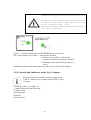
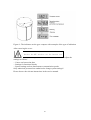
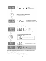
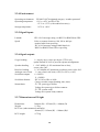
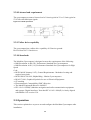
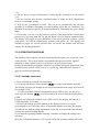
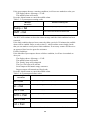
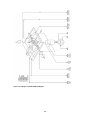
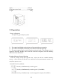
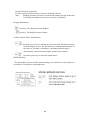
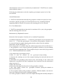
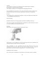
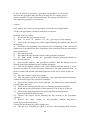
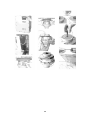
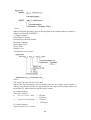
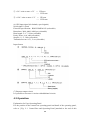
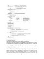
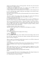
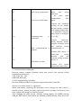
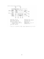
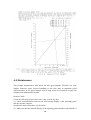
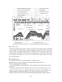
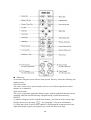
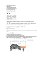
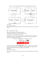
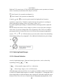
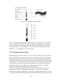
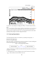
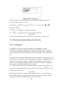
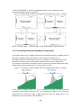
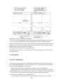
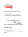
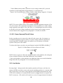
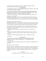
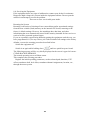
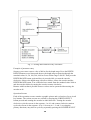
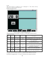
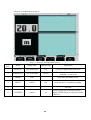
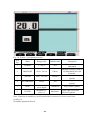
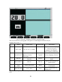
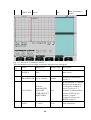
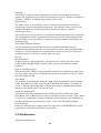
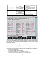
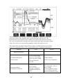
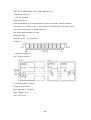
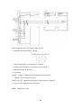
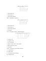
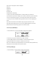
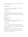
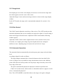
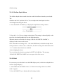
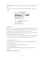
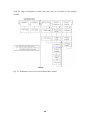
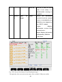
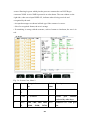
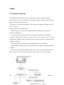
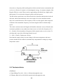
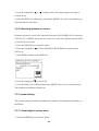
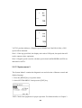
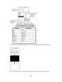
1.3.9. Adjusting Receiver Gain Controls The receiver gain control for each channel illustrated at right. Each control adjusts the
rate of amplification of echo signals. For stable digital depth reading or automatic
bottom tracking operation, adjust the gain so that the bottom echo is always displayed
in red, orange or yellow (or one of the three strongest echo colors, if you have
changed the color assignments*). The TVG** level (shallow gain suppression level)
may also have to be increased to prevent surface clutters from disturbing digital depth
reading.
* See paragraph 4.9.2 for details on user–definable colors.
** See paragraph 3.10 for details.
Lack of receiver gain will cause the missing–bottom alarm to be triggered. See
paragraph 3.12.3 for information on the alarm.
Figure 3-32 Receiver Gain Controls
1.3.10. Adjusting TVG Controls TVG stands for time–varied gain. The TVG control is designed to sharply drop the
receiver gain on each transmission, and then gradually recover the normal gain level
as the transmitted signal travels deeper toward the bottom. When the control is set
fully counterclockwise, both the amount of initial gain drop (or initial gain
suppression) and the range of TVG effectiveness are at a maximum level. As you turn
the control in the clockwise direction, the amount of suppression and range will
decrease. No TVG effect is available with the control fully clockwise. In situations
where digital depth reading is intermittent or automatic bottom tracking operation is
erratic despite of the bottom echo showing in red, orange or yellow (or in three user–
defined strongest colors), suspect that surface clutters (explained below) are
responsible, forcing such echoes to be accepted as a random bottom echo. To correct
the problem, turn the appropriate TVG control in CCW direction until normal readout
or bottom tracking function is restored or until such echoes become visible in weaker
colors while keeping the bottom reflection in the same (three strongest) colors by
slightly increasing the gain as necessary.
Figure 3-33 Adjusting TVG Level – Example
(a) Reflections near transducer face with no TVG effect
119