1
léÉê~íáçåI=fåëí~ää~íáçå=~åÇ=pÉêîáÅÉ=j~åì~ä
lêáÖáå~ä=açÅìãÉåí~íáçå=L=hÉÉé=Ñçê=cìíìêÉ=oÉÑÉêÉåÅÉ
k^sfd^q u jh N
aáÖáí~ä=dóêçÅçãé~ëë=póëíÉãë
qóéÉ=QVNQJ`^I=píçÅâ=kçK=TQUMT=~åÇ=qóéÉ=QVNQJ``I=píçÅâ=kçK=TQUNN
MQVNQJMNOUJMN
MRSPQPLbI=NN=kçî=OMNP
kçêíÜêçé=dêìãã~å=péÉêêó=j~êáåÉ=_KsK=EoÉéêÉëÉåí~íáîÉ=lÑÑáÅÉF
tçäíã~åëíêK=NV=√=aJOMMVT=√=e~ãÄìêÖI=dÉêã~åó
qÉäKW HQVJQMJOVV MMJM=√=c~ñW HQVJQMJOVV MMJNQS=√=bJã~áäW ëÉêîáÅÉKÇÉ]ëéÉêêóKåÖÅKÅçã
MRSPQPLb
k^sfd^q u jh N
© 2013 Northrop Grumman Sperry Marine B.V.
This document and the information herein is the intellectual property of Northrop Grumman
Sperry Marine B.V. [NGSM BV] and it’s associate companies and may not be copied, reproduced
or translated without the express permission of NGSM BV.
Specifications were correct at time of press but may be varied in accordance with NGSM BV’s
policy of continuous product development.
Any technical content should be verified with NGSM BV.
Sperry Marine, with major engineering and support offices in New Malden, England, and
Hamburg, Germany, is part of the Northrop Grumman Navigation & Maritime Systems Division
N&MSD.
oÉîáëáçå=oÉÅçêÇ
oÉîK
a~íÉ
oÉã~êâë
E
11 Nov 2013
Factory setting menu (technical pages) amended, service setup 2
amended, installation procedure and power-up function test amended.
D
11 Sep 2013
Updated version, new service setup options (Course Bus, THS/HDT,
ROT filter) added; technical data amended, checklist procedures
added, spare parts added; chapter removal/installation added.
C
08 May 2008
Added new options (AD10 output, alarm mute relay, speed filter).
B
17 Nov 2006
Removed gyrosphere installation/service instructions. These are now
contained in separate documents delivered with the respective gyrosphere and container.
All information regarding the master PCB refers to the new PCB, stock
no. 20672.
A
18 Jan 2005
Initial release.
k^sfd^q u jh N
MRSPQPLb
`çåíÉåíë
p~ÑÉíó=fåëíêìÅíáçåë
p~ÑÉíó=kçíáÅÉ=`çåîÉåíáçåëKKKKKKKKKKKKKKKKKKKKKKKKKKKKKKKKKKKKKKKKKKKKKKKKKKKKKKKKKKKKKKKKKKKKKKKK îáá
dÉåÉê~ä=p~ÑÉíó=fåÑçêã~íáçå=Ñçê=íÜÉ=léÉê~íçê KKKKKKKKKKKKKKKKKKKKKKKKKKKKKKKKKKKKKKKKK îááá
dÉåÉê~ä=p~ÑÉíó=fåÑçêã~íáçå=Ñçê=pÉêîáÅÉ=mÉêëçååÉäKKKKKKKKKKKKKKKKKKKKKKKKKKKKKKKKKK ñáá
`Ü~éíÉê=NW fåíêçÇìÅíáçå
NKN
póëíÉã=aÉëÅêáéíáçåKKKKKKKKKKKKKKKKKKKKKKKKKKKKKKKKKKKKKKKKKKKKKKKKKKKKKKKKKKKKKKKKKKKKKKKKKKKKKKKKKKK NJN
fåíÉåÇÉÇ=rëÉ KKKKKKKKKKKKKKKKKKKKKKKKKKKKKKKKKKKKKKKKKKKKKKKKKKKKKKKKKKKKKKKKKKKKKKKKKKKKKKKKKKKKKKKKKKKKKKKNJN
kçí=fåíÉåÇÉÇ=rëÉKKKKKKKKKKKKKKKKKKKKKKKKKKKKKKKKKKKKKKKKKKKKKKKKKKKKKKKKKKKKKKKKKKKKKKKKKKKKKKKKKKKKKKKKKNJN
NKO
póëíÉã=lîÉêîáÉï=~åÇ=j~áå=`çãéçåÉåíë KKKKKKKKKKKKKKKKKKKKKKKKKKKKKKKKKKKKKKKKKKKKKK NJO
i~ÄÉä=~åÇ=íóéÉ=ä~ÄÉä KKKKKKKKKKKKKKKKKKKKKKKKKKKKKKKKKKKKKKKKKKKKKKKKKKKKKKKKKKKKKKKKKKKKKKKKKKKKKKKKKKKKKNJP
j~áå=ÅçãéçåÉåíë KKKKKKKKKKKKKKKKKKKKKKKKKKKKKKKKKKKKKKKKKKKKKKKKKKKKKKKKKKKKKKKKKKKKKKKKKKKKKKKKKKKKKKKKNJQ
NKP
aÉëáÖå=~åÇ=j~áå=cÉ~íìêÉëKKKKKKKKKKKKKKKKKKKKKKKKKKKKKKKKKKKKKKKKKKKKKKKKKKKKKKKKKKKKKKKKKKKKKKKK NJS
NKQ
léÉê~íáåÖ=mêáåÅáéäÉ KKKKKKKKKKKKKKKKKKKKKKKKKKKKKKKKKKKKKKKKKKKKKKKKKKKKKKKKKKKKKKKKKKKKKKKKKKKKKKKKKKK NJT
aóå~ãáÅ=eÉ~ÇáåÖ=bêêçê KKKKKKKKKKKKKKKKKKKKKKKKKKKKKKKKKKKKKKKKKKKKKKKKKKKKKKKKKKKKKKKKKKKKKKKKKKKKKKKKNJU
NKR
bñ~ãéäÉ=póëíÉã=`çåÑáÖìê~íáçåë KKKKKKKKKKKKKKKKKKKKKKKKKKKKKKKKKKKKKKKKKKKKKKKKKKKKKKKKKKKKK NJV
pí~åÇ~äçåÉ=dóêçÅçãé~ëëLqj`=póëíÉã KKKKKKKKKKKKKKKKKKKKKKKKKKKKKKKKKKKKKKKKKKKKKKKKKKKKKKNJV
aì~ä=k^sfd^q u jh N=dóêçÅçãé~ëëLqj`=póëíÉã KKKKKKKKKKKKKKKKKKKKKKKKKKKKKKKKKKKK NJNM
NKS
qÉÅÜåáÅ~ä=a~í~KKKKKKKKKKKKKKKKKKKKKKKKKKKKKKKKKKKKKKKKKKKKKKKKKKKKKKKKKKKKKKKKKKKKKKKKKKKKKKKKKKKKKKKKKKKNJNN
NKT
j~êáåÉ=bèìáéãÉåí=aáêÉÅíáîÉ=b`=aÉÅä~ê~íáçå=çÑ=`çåÑçêãáíóKKKKKKKKKKKKKKKK NJNQ
`Ü~éíÉê=OW léÉê~íáçå
OKN
léÉê~íáåÖ=`çåÇáíáçåë KKKKKKKKKKKKKKKKKKKKKKKKKKKKKKKKKKKKKKKKKKKKKKKKKKKKKKKKKKKKKKKKKKKKKKKKKKKKKKK OJN
OKO
aáëéä~ó=~åÇ=léÉê~íáåÖ=hÉóë KKKKKKKKKKKKKKKKKKKKKKKKKKKKKKKKKKKKKKKKKKKKKKKKKKKKKKKKKKKKKKKKKKKKK OJO
`çåíêçä=~åÇ=aáëéä~ó=råáí=E`arF KKKKKKKKKKKKKKKKKKKKKKKKKKKKKKKKKKKKKKKKKKKKKKKKKKKKKKKKKKKKKKKKKKK OJO
OKP
bñíÉêå~ä=`çåíêçä=aÉîáÅÉë KKKKKKKKKKKKKKKKKKKKKKKKKKKKKKKKKKKKKKKKKKKKKKKKKKKKKKKKKKKKKKKKKKKKKKKKKK OJP
OKQ
mçïÉêJìé=pÉèìÉåÅÉ KKKKKKKKKKKKKKKKKKKKKKKKKKKKKKKKKKKKKKKKKKKKKKKKKKKKKKKKKKKKKKKKKKKKKKKKKKKKKKKKKK OJQ
OKR
pÉäÉÅíáåÖ=íÜÉ=^ÅíáîÉ=eÉ~ÇáåÖ=pçìêÅÉKKKKKKKKKKKKKKKKKKKKKKKKKKKKKKKKKKKKKKKKKKKKKKKKKKKKKK OJR
OKS
^ÇàìëíáåÖ=íÜÉ=aáëéä~ó=_êáÖÜíåÉëë KKKKKKKKKKKKKKKKKKKKKKKKKKKKKKKKKKKKKKKKKKKKKKKKKKKKKKKKKKKK OJS
OKT
léíáçå~ä=cìåÅíáçåëKKKKKKKKKKKKKKKKKKKKKKKKKKKKKKKKKKKKKKKKKKKKKKKKKKKKKKKKKKKKKKKKKKKKKKKKKKKKKKKKKKKK OJS
jìíáåÖ=^ä~êãë=oÉãçíÉäó KKKKKKKKKKKKKKKKKKKKKKKKKKKKKKKKKKKKKKKKKKKKKKKKKKKKKKKKKKKKKKKKKKKKKKKKKKKK OJS
oÉîÉêëáåÖ=íÜÉ=eÉ~ÇáåÖ=aáëéä~ó=ENUMø=çÑÑëÉíF KKKKKKKKKKKKKKKKKKKKKKKKKKKKKKKKKKKKKKKKKKKKKKK OJS
oÉëÉííáåÖL^ÅâåçïäÉÇÖáåÖ=~=`Éåíê~ä=t~íÅÜ=^ä~êã KKKKKKKKKKKKKKKKKKKKKKKKKKKKKKKKKKKKKKK OJS
OKU
léÉê~íáåÖ=jÉåì KKKKKKKKKKKKKKKKKKKKKKKKKKKKKKKKKKKKKKKKKKKKKKKKKKKKKKKKKKKKKKKKKKKKKKKKKKKKKKKKKKKKKKKK OJT
båíÉêáåÖ=~åÇ=nìáííáåÖ=íÜÉ=j~áå=jÉåìKKKKKKKKKKKKKKKKKKKKKKKKKKKKKKKKKKKKKKKKKKKKKKKKKKKKKKKKK OJT
k~îáÖ~íáåÖ=íÜÉ=jÉåìKKKKKKKKKKKKKKKKKKKKKKKKKKKKKKKKKKKKKKKKKKKKKKKKKKKKKKKKKKKKKKKKKKKKKKKKKKKKKKKKKKK OJT
pÉäÉÅíáåÖ=m~ê~ãÉíÉê=pÉííáåÖëKKKKKKKKKKKKKKKKKKKKKKKKKKKKKKKKKKKKKKKKKKKKKKKKKKKKKKKKKKKKKKKKKKKKKK OJU
bÇáíáåÖ=m~ê~ãÉíÉê=s~äìÉë KKKKKKKKKKKKKKKKKKKKKKKKKKKKKKKKKKKKKKKKKKKKKKKKKKKKKKKKKKKKKKKKKKKKKKKKKKKK OJU
OKV
pÉäÉÅíáåÖ=~=aáëéä~ó=a~í~=m~ÖÉ KKKKKKKKKKKKKKKKKKKKKKKKKKKKKKKKKKKKKKKKKKKKKKKKKKKKKKKKKKKKKKKKK OJV
OKNM
j~åì~ä=pÉííáåÖë=jÉåì KKKKKKKKKKKKKKKKKKKKKKKKKKKKKKKKKKKKKKKKKKKKKKKKKKKKKKKKKKKKKKKKKKKKKKKKKKK OJNM
`~éíáçå=Ñçê=pÉäÉÅíáåÖ=~åÇ=bÇáíáåÖ KKKKKKKKKKKKKKKKKKKKKKKKKKKKKKKKKKKKKKKKKKKKKKKKKKKKKKKKKKKKKKKOJNM
ááá
MRSPQPLb
k^sfd^q u jh N
j~åì~ä=pÉííáåÖë=Ó=lîÉêîáÉï KKKKKKKKKKKKKKKKKKKKKKKKKKKKKKKKKKKKKKKKKKKKKKKKKKKKKKKKKKKKKKKKKKKKKKOJNN
j~åì~ä=pÉííáåÖë=Ó=m~ê~ãÉíÉêë KKKKKKKKKKKKKKKKKKKKKKKKKKKKKKKKKKKKKKKKKKKKKKKKKKKKKKKKKKKKKKKKKK OJNP
OKNN
rëÉê=pÉíìé KKKKKKKKKKKKKKKKKKKKKKKKKKKKKKKKKKKKKKKKKKKKKKKKKKKKKKKKKKKKKKKKKKKKKKKKKKKKKKKKKKKKKKKKKKKKKKK OJNT
rëÉê=pÉíìé=Ó=lîÉêîáÉï KKKKKKKKKKKKKKKKKKKKKKKKKKKKKKKKKKKKKKKKKKKKKKKKKKKKKKKKKKKKKKKKKKKKKKKKKKKKK OJNT
rëÉê=pÉíìé=Ó=m~ê~ãÉíÉêë KKKKKKKKKKKKKKKKKKKKKKKKKKKKKKKKKKKKKKKKKKKKKKKKKKKKKKKKKKKKKKKKKKKKKKKKKK OJNU
`Ü~éíÉê=PW bêêçêë=~åÇ=^ä~êãë
PKN
^ä~êã=fåÇáÅ~íáçå KKKKKKKKKKKKKKKKKKKKKKKKKKKKKKKKKKKKKKKKKKKKKKKKKKKKKKKKKKKKKKKKKKKKKKKKKKKKKKKKKKKKKKKK PJN
^ìÇáÄäÉ=^ä~êã=fåÇáÅ~íáçåKKKKKKKKKKKKKKKKKKKKKKKKKKKKKKKKKKKKKKKKKKKKKKKKKKKKKKKKKKKKKKKKKKKKKKKKKKKKKK PJN
sáëì~ä=^ä~êã=fåÇáÅ~íáçå KKKKKKKKKKKKKKKKKKKKKKKKKKKKKKKKKKKKKKKKKKKKKKKKKKKKKKKKKKKKKKKKKKKKKKKKKKKKKKKK PJN
PKO
^ÅâåçïäÉÇÖáåÖ=^ä~êãëLjìíáåÖ=íÜÉ=^ìÇáÄäÉ=^ä~êã KKKKKKKKKKKKKKKKKKKKKKKKKKKKKKK PJO
^ä~êã=^ÅâåçïäÉÇÖÉ KKKKKKKKKKKKKKKKKKKKKKKKKKKKKKKKKKKKKKKKKKKKKKKKKKKKKKKKKKKKKKKKKKKKKKKKKKKKKKKKKKKK PJO
^ä~êã=jìíÉ KKKKKKKKKKKKKKKKKKKKKKKKKKKKKKKKKKKKKKKKKKKKKKKKKKKKKKKKKKKKKKKKKKKKKKKKKKKKKKKKKKKKKKKKKKKKKKKKK PJO
PKP
bêêçê=ãÉëë~ÖÉë KKKKKKKKKKKKKKKKKKKKKKKKKKKKKKKKKKKKKKKKKKKKKKKKKKKKKKKKKKKKKKKKKKKKKKKKKKKKKKKKKKKKKKKKKK PJP
`Ü~éíÉê=QW pÅÜÉÇìäÉÇ=j~áåíÉå~åÅÉ
QKN
j~áåíÉå~åÅÉ=çÑ=íÜÉ=k^sfd^q=u=jh=N KKKKKKKKKKKKKKKKKKKKKKKKKKKKKKKKKKKKKKKKKKKKKKKKKKKKK QJN
`äÉ~åáåÖ=çÑ=`çãé~ëë=eçìëáåÖ KKKKKKKKKKKKKKKKKKKKKKKKKKKKKKKKKKKKKKKKKKKKKKKKKKKKKKKKKKKKKKKKKKKK QJN
`äÉ~åáåÖ=çÑ=^áê=fåäÉí=dêáääKKKKKKKKKKKKKKKKKKKKKKKKKKKKKKKKKKKKKKKKKKKKKKKKKKKKKKKKKKKKKKKKKKKKKKKKKKKKKK QJN
QKO
dóêçëéÜÉêÉ=j~áåíÉå~åÅÉ KKKKKKKKKKKKKKKKKKKKKKKKKKKKKKKKKKKKKKKKKKKKKKKKKKKKKKKKKKKKKKKKKKKKKKKKK QJO
NUJjçåíÜ=j~áåíÉå~åÅÉ KKKKKKKKKKKKKKKKKKKKKKKKKKKKKKKKKKKKKKKKKKKKKKKKKKKKKKKKKKKKKKKKKKKKKKKKKKKKKKK QJO
cáîÉJvÉ~ê=j~áåíÉå~åÅÉ KKKKKKKKKKKKKKKKKKKKKKKKKKKKKKKKKKKKKKKKKKKKKKKKKKKKKKKKKKKKKKKKKKKKKKKKKKKKKKKK QJP
`Ü~éíÉê=RW mêÉîÉåíáîÉ=j~áåíÉå~åÅÉ
RKN
mêçíÉÅíáåÖ=íÜÉ=dóêçëéÜÉêÉ=Ñêçã=içï=qÉãéÉê~íìêÉëKKKKKKKKKKKKKKKKKKKKKKKKKKKKKK RJN
RKO
oÉãçîáåÖ=íÜÉ=dóêçëéÜÉêÉ=`çåí~áåÉê=Ñêçã=íÜÉ=`çãé~ëë=eçìëáåÖ KKKKKK RJO
RKP
fåëí~ääáåÖ=íÜÉ=dóêçëéÜÉêÉ=`çåí~áåÉê=áå=íÜÉ=`çãé~ëë=eçìëáåÖKKKKKKKKKKKKK RJR
RKQ
mçïÉêJìé=cìåÅíáçå=qÉëíKKKKKKKKKKKKKKKKKKKKKKKKKKKKKKKKKKKKKKKKKKKKKKKKKKKKKKKKKKKKKKKKKKKKKKKKKKKKK RJT
dóêçëéÜÉêÉ=`ìêêÉåí=mêÉäáãáå~êáÉë KKKKKKKKKKKKKKKKKKKKKKKKKKKKKKKKKKKKKKKKKKKKKKKKKKKKKKKKKKKKKKK RJT
m~êíëI=ã~íÉêá~äë=~åÇ=íççäë=êÉèìáêÉÇ KKKKKKKKKKKKKKKKKKKKKKKKKKKKKKKKKKKKKKKKKKKKKKKKKKKKKKKKKKKKKK RJU
mêçÅÉÇìêÉ KKKKKKKKKKKKKKKKKKKKKKKKKKKKKKKKKKKKKKKKKKKKKKKKKKKKKKKKKKKKKKKKKKKKKKKKKKKKKKKKKKKKKKKKKKKKKKKKKKKK RJU
`Ü~éíÉê=SW oÉãçî~äLfåëí~ää~íáçå=çÑ=`çãéçåÉåíë
SKN
oÉãçîáåÖ=póëíÉã=`çãéçåÉåíë=Ñêçã=íÜÉ=`çãé~ëë=eçìëáåÖ KKKKKKKKKKKKKK SJN
mêçÅÉÇìêÉ KKKKKKKKKKKKKKKKKKKKKKKKKKKKKKKKKKKKKKKKKKKKKKKKKKKKKKKKKKKKKKKKKKKKKKKKKKKKKKKKKKKKKKKKKKKKKKKKKKKK SJO
SKO
fåëí~ääáåÖ=póëíÉã=`çãéçåÉåíë=áåíç=íÜÉ=`çãé~ëë=eçìëáåÖ KKKKKKKKKKKKKKKKK SJV
mêçÅÉÇìêÉ KKKKKKKKKKKKKKKKKKKKKKKKKKKKKKKKKKKKKKKKKKKKKKKKKKKKKKKKKKKKKKKKKKKKKKKKKKKKKKKKKKKKKKKKKKKKKKKKKKKK SJV
`Ü~éíÉê=TW póëíÉã=fåëí~ää~íáçå
áî
TKN
jÉÅÜ~åáÅ~ä=fåëí~ää~íáçåKKKKKKKKKKKKKKKKKKKKKKKKKKKKKKKKKKKKKKKKKKKKKKKKKKKKKKKKKKKKKKKKKKKKKKKKKKKKK TJN
fåëí~ääáåÖ=íÜÉ=`çãé~ëë=eçìëáåÖKKKKKKKKKKKKKKKKKKKKKKKKKKKKKKKKKKKKKKKKKKKKKKKKKKKKKKKKKKKKKKKKKK TJN
TKO
bäÉÅíêáÅ~ä=fåëí~ää~íáçåKKKKKKKKKKKKKKKKKKKKKKKKKKKKKKKKKKKKKKKKKKKKKKKKKKKKKKKKKKKKKKKKKKKKKKKKKKKKKKKKK TJO
^`=pìééäó=mçïÉê=`çåÑáÖìê~íáçå KKKKKKKKKKKKKKKKKKKKKKKKKKKKKKKKKKKKKKKKKKKKKKKKKKKKKKKKKKKKKKKKKK TJO
táêáåÖ=ré=íÜÉ=póëíÉã KKKKKKKKKKKKKKKKKKKKKKKKKKKKKKKKKKKKKKKKKKKKKKKKKKKKKKKKKKKKKKKKKKKKKKKKKKKKKKKKK TJP
TKP
dóêçëéÜÉêÉ=fåëí~ää~íáçå KKKKKKKKKKKKKKKKKKKKKKKKKKKKKKKKKKKKKKKKKKKKKKKKKKKKKKKKKKKKKKKKKKKKKKKKKKKK TJQ
k^sfd^q u jh N
MRSPQPLb
TKQ
fåáíá~ä=póëíÉã=`çåÑáÖìê~íáçå KKKKKKKKKKKKKKKKKKKKKKKKKKKKKKKKKKKKKKKKKKKKKKKKKKKKKKKKKKKKKKKKKKKK TJR
`çåÑáÖìê~íáçå=çÑ=íÜÉ=póëíÉã KKKKKKKKKKKKKKKKKKKKKKKKKKKKKKKKKKKKKKKKKKKKKKKKKKKKKKKKKKKKKKKKKKKKKKK TJR
cáå~äáòáåÖ=íÜÉ=fåëí~ää~íáçå KKKKKKKKKKKKKKKKKKKKKKKKKKKKKKKKKKKKKKKKKKKKKKKKKKKKKKKKKKKKKKKKKKKKKKKKKKKKK TJS
TKR
^äáÖåãÉåí=bêêçê=`çêêÉÅíáçå KKKKKKKKKKKKKKKKKKKKKKKKKKKKKKKKKKKKKKKKKKKKKKKKKKKKKKKKKKKKKKKKKKKKKK TJT
TKS
j~ÖåÉíáÅ=`çãé~ëë=`~äáÄê~íáçåKKKKKKKKKKKKKKKKKKKKKKKKKKKKKKKKKKKKKKKKKKKKKKKKKKKKKKKKKKKKKKKK TJU
TKT
fåëí~ää~íáçå=`ÜÉÅâ=mêçÅÉÇìêÉëKKKKKKKKKKKKKKKKKKKKKKKKKKKKKKKKKKKKKKKKKKKKKKKKKKKKKKKKKKKKKKKKKTJNN
jÉÅÜ~åáÅ~ä=fåëí~ää~íáçå=`ÜÉÅâ=mêçÅÉÇìêÉKKKKKKKKKKKKKKKKKKKKKKKKKKKKKKKKKKKKKKKKKKKKKKKKKKK TJNN
bäÉÅíêáÅ~ä=fåëí~ää~íáçå=`ÜÉÅâ=mêçÅÉÇìêÉ KKKKKKKKKKKKKKKKKKKKKKKKKKKKKKKKKKKKKKKKKKKKKKKKKKKKKK TJNN
póëíÉã=`çåÑáÖìê~íáçå=`ÜÉÅâ=mêçÅÉÇìêÉKKKKKKKKKKKKKKKKKKKKKKKKKKKKKKKKKKKKKKKKKKKKKKKKKKKKKTJNO
`Ü~éíÉê=UW póëíÉã=`çåÑáÖìê~íáçå
UKN
`çåÑáÖìê~íáçå=jÉåì=J=pÉêîáÅÉ=pÉíìé=N KKKKKKKKKKKKKKKKKKKKKKKKKKKKKKKKKKKKKKKKKKKKKKKKKKKK UJN
pÉíìé=^ÅÅÉëë=`çÇÉ KKKKKKKKKKKKKKKKKKKKKKKKKKKKKKKKKKKKKKKKKKKKKKKKKKKKKKKKKKKKKKKKKKKKKKKKKKKKKKKKKKKKK UJN
pÉêîáÅÉJpÉíìé=N=Ó=lîÉêîáÉïKKKKKKKKKKKKKKKKKKKKKKKKKKKKKKKKKKKKKKKKKKKKKKKKKKKKKKKKKKKKKKKKKKKKKKKK UJO
pÉêîáÅÉ=pÉíìé=N=Ó=m~ê~ãÉíÉêëKKKKKKKKKKKKKKKKKKKKKKKKKKKKKKKKKKKKKKKKKKKKKKKKKKKKKKKKKKKKKKKKKKKKK UJS
UKO
pÉêîáÅÉ=fåÑç=jÉåì=J=pÉêîáÅÉ=pÉíìé=O KKKKKKKKKKKKKKKKKKKKKKKKKKKKKKKKKKKKKKKKKKKKKKKKKKKKK UJNV
pÉêîáÅÉ=pÉíìé=O=Ó=^ÅÅÉëë=`çÇÉ KKKKKKKKKKKKKKKKKKKKKKKKKKKKKKKKKKKKKKKKKKKKKKKKKKKKKKKKKKKKKKKKKUJNV
pÉêîáÅÉ=pÉíìé=O=Ó=lîÉêîáÉïKKKKKKKKKKKKKKKKKKKKKKKKKKKKKKKKKKKKKKKKKKKKKKKKKKKKKKKKKKKKKKKKKKKKKK UJOM
pÉêîáÅÉ=pÉíìé=O=Ó=m~ê~ãÉíÉêëKKKKKKKKKKKKKKKKKKKKKKKKKKKKKKKKKKKKKKKKKKKKKKKKKKKKKKKKKKKKKKKKKKK UJON
UKP
c~Åíçêó=pÉííáåÖë=jÉåì=EqÉÅÜåáÅ~ä=m~ÖÉëF KKKKKKKKKKKKKKKKKKKKKKKKKKKKKKKKKKKKKKKKKKKKK UJOP
pÉíìé=^ÅÅÉëë=`çÇÉ KKKKKKKKKKKKKKKKKKKKKKKKKKKKKKKKKKKKKKKKKKKKKKKKKKKKKKKKKKKKKKKKKKKKKKKKKKKKKKKKKKK UJOP
qÉÅÜåáÅ~ä=m~ÖÉë=Ó=lîÉêîáÉï KKKKKKKKKKKKKKKKKKKKKKKKKKKKKKKKKKKKKKKKKKKKKKKKKKKKKKKKKKKKKKKKKKKKKK UJOP
qÉÅÜåáÅ~ä=m~ÖÉë=Ó=m~ê~ãÉíÉêë KKKKKKKKKKKKKKKKKKKKKKKKKKKKKKKKKKKKKKKKKKKKKKKKKKKKKKKKKKKKKKKKKKK UJOQ
`Ü~éíÉê=VW qêçìÄäÉëÜççíáåÖ
VKN
qêçìÄäÉëÜççíáåÖ=fåëíêìÅíáçåë KKKKKKKKKKKKKKKKKKKKKKKKKKKKKKKKKKKKKKKKKKKKKKKKKKKKKKKKKKKKKKKKKKK VJN
VKO
içÅ~íáçå=çÑ=m~êíë=çå=íÜÉ=j~ëíÉê=m`_ KKKKKKKKKKKKKKKKKKKKKKKKKKKKKKKKKKKKKKKKKKKKKKKKKKKKKK VJO
bñÅÜ~åÖÉ~ÄäÉ=`çãéçåÉåíëKKKKKKKKKKKKKKKKKKKKKKKKKKKKKKKKKKKKKKKKKKKKKKKKKKKKKKKKKKKKKKKKKKKKKKKKK VJP
`çååÉÅíçêëKKKKKKKKKKKKKKKKKKKKKKKKKKKKKKKKKKKKKKKKKKKKKKKKKKKKKKKKKKKKKKKKKKKKKKKKKKKKKKKKKKKKKKKKKKKKKKKKKK VJP
qÉëí=oÉëáëíçê=L=qêáãéçíëKKKKKKKKKKKKKKKKKKKKKKKKKKKKKKKKKKKKKKKKKKKKKKKKKKKKKKKKKKKKKKKKKKKKKKKKKKKKKKK VJQ
aá~ÖåçëíáÅ=ibaëKKKKKKKKKKKKKKKKKKKKKKKKKKKKKKKKKKKKKKKKKKKKKKKKKKKKKKKKKKKKKKKKKKKKKKKKKKKKKKKKKKKKKKKKKK VJQ
`Ü~éíÉê=NMW `çêêÉÅíáîÉ=j~áåíÉå~åÅÉ
NMKN
bñÅÜ~åÖáåÖ=íÜÉ=póëíÉã=pçÑíï~êÉ KKKKKKKKKKKKKKKKKKKKKKKKKKKKKKKKKKKKKKKKKKKKKKKKKKKKKKKKK NMJN
NMKO
oÉéä~ÅáåÖ=pçÅâÉíÉÇ=f`ë KKKKKKKKKKKKKKKKKKKKKKKKKKKKKKKKKKKKKKKKKKKKKKKKKKKKKKKKKKKKKKKKKKKKKKKKKK NMJO
`Ü~éíÉê=NNW k^sfd^q u=jhN=pé~êÉ=m~êíë
NNKN
fääìëíê~íÉÇ=m~êíë=iáëí=EfmiF=lîÉêîáÉï KKKKKKKKKKKKKKKKKKKKKKKKKKKKKKKKKKKKKKKKKKKKKKKKKKKKKKKNNJN
^ÄÄêÉîá~íáçåë
^ééÉåÇáñ
^
pÉíìé=~åÇ=`çåÑáÖìê~íáçå=q~ÄäÉë
_
aê~ïáåÖë
î
MRSPQPLb
îá
k^sfd^q u jh N
k^sfd^q u jh N
MRSPQPLb
p~ÑÉíó=fåëíêìÅíáçåë
p~ÑÉíó=kçíáÅÉ=`çåîÉåíáçåë
The following safety notice conventions are followed throughout this
manual:
kçíÉ
a^kdbo
A a~åÖÉê notice begins with the named type of
danger and contains an operating or maintenance procedure, practice, condition, statement,
etc., which, if not strictly observed, ïáää=êÉëìäí=áå=
áåàìêó=çê=ÇÉ~íÜ=çÑ=éÉêëçååÉäK
t^okfkd
A t~êåáåÖ notice begins with the named type of
warning and contains an operating or maintenance procedure, practice, condition, statement,
etc., which, if not strictly observed, ÅçìäÇ=êÉëìäí=
áå=áåàìêó=çê=ÇÉ~íÜ=çÑ=éÉêëçååÉäK
`^rqflk
A `~ìíáçå notice begins with the named type of
caution and contains an operating or maintenance procedure, practice, condition, statement,
etc., which, if not strictly observed, ÅçìäÇ=êÉëìäí=
áå=Ç~ã~ÖÉ=íçI=çê=ÇÉëíêìÅíáçå=çÑ=ÉèìáéãÉåíK
A kçíÉ contains an essential operating or maintenance procedure, condition or statement,
which is considered important enough to be
highlighted.
Special safety symbols may be used in this
manual to indicate:
oáëâ=çÑ=ÉäÉÅíêáÅ~ä=ëÜçÅâK
Used in conjunction with a a~åÖÉê or t~êåáåÖ
notice.
Electrical components sensitive to electrostatic
discharge.
Used in conjunction with a `~ìíáçå notice.
p~ÑÉíó=fåëíêìÅíáçåë
îáá
MRSPQPLb
k^sfd^q u jh N
dÉåÉê~ä=p~ÑÉíó=fåÑçêã~íáçå=Ñçê=íÜÉ=léÉê~íçê
îááá
t^okfkd
oáëâ=çÑ=ÇÉîá~íáçå
kÉîÉê=êÉäó=çå=çåÉ=ÜÉ~ÇáåÖ=ëçìêÅÉ=~äçåÉ=íç=å~îáÖ~íÉ=~=îÉëëÉäK
^äï~óë=ÅçåÑáêã=íÜÉ=éä~ìëáÄáäáíó=çÑ=íÜÉ=k^sfd^q u jh N=ÜÉ~ÇáåÖ=~åÇ=íÜÉ=
ëéÉÉÇ=~åÇ=éçëáíáçå=áåéìí=Ç~í~=~Ö~áåëí=~ää=~î~áä~ÄäÉ=~áÇë=íç=å~îáÖ~íáçåK
t^okfkd
iáãáíÉÇ=ÜÉ~ÇáåÖ=Ç~í~=~ÅÅìê~Åó=ÇìêáåÖ=ëÉííäáåÖ=íáãÉ
^ÑíÉê=~=éçïÉêJìé=Ñêçã=ÅçäÇI=íÜÉ=k^sfd^q u jh N=êÉèìáêÉë=~=ëÉííäáåÖ=íáãÉ=
çÑ=íÜêÉÉ=Üçìêë=ÄÉÑçêÉ=êÉäá~ÄäÉ=ÜÉ~ÇáåÖ=Ç~í~=áë=~î~áä~ÄäÉK
mçïÉê=ìé=íÜÉ=ëóëíÉã=~í=äÉ~ëí=íÜêÉÉ=Üçìêë=ÄÉÑçêÉ=äÉ~îáåÖ=Ü~êÄçìêK
mçïÉê=Ççïå=íÜÉ=ëóëíÉã=ÇìêáåÖ=äçåÖ=ÇçÅâáåÖ=éÉêáçÇë=çåäóK
j~âÉ=ëìêÉ=íÜ~í=íÜÉ=k^sfd^q u jh N=Ü~ë=ëÉííäÉÇ=ÄÉÑçêÉ=ìëáåÖ=áíë=ÜÉ~ÇáåÖ=
~ë=íÜÉ=êÉÑÉêÉåÅÉ=Ñçê=ÜÉ~ÇáåÖ=Åçåíêçä=ëóëíÉãëI=o^a^oI=b`afpI=ÉíÅK
^=ã~ÖåÉíáÅ=Åçãé~ëë=ÜÉ~ÇáåÖ=ëçìêÅÉ=ëÜçìäÇ=ÄÉ=ëÉäÉÅíÉÇ=~ë=êÉÑÉêÉåÅÉ=
çåäó=áå=Å~ëÉ=çÑ=Ñ~áäìêÉ=çÑ=íÜÉ=ÖóêçÅçãé~ëëEÉëFK
t^okfkd
oáëâ=çÑ=ãáëìë~ÖÉ
_ÉÑçêÉ=ìëáåÖ=íÜÉ=k^sfd^q u jh NI=çéÉê~íçêë=ãìëí=ÄÉ=~ééêçéêá~íÉäó=
íê~áåÉÇ=~åÇ=Ñ~ãáäá~ê=ïáíÜ=~ää=çéÉê~íáåÖ=éêçÅÉÇìêÉë=~åÇ=ë~ÑÉíó=áåëíêìÅJ
íáçåë=Åçåí~áåÉÇ=áå=íÜáë=ã~åì~äK=qÜÉ=ã~åì~ä=áë=íç=ÄÉ=ÅçãéäÉíÉäó=êÉ~Ç=
ÄÉÑçêÉ=íÜÉ=Ñáêëí=ìë~ÖÉ=çÑ=íÜÉ=k^sfd^q u jh NK
hÉÉé=íÜáë=ã~åì~ä=ÇìêáåÖ=íÜÉ=ÉåíáêÉ=ëÉêîáÅÉ=äáÑÉ=çÑ=íÜÉ=éêçÇìÅí=~åÇ=~äï~óë=
Ü~îÉ=áí=êÉ~Çáäó=~î~áä~ÄäÉ=áå=~=åÉ~êÄó=äçÅ~íáçå=Ñçê=êÉÑÉêÉåÅÉK
`^rqflk
Risk of damage/destruction through low temperatures
The supporting fluid in the gyrosphere container will start freezing at
temperatures below 0° C.
The NAVIGAT X MK 1 must no longer be operated when the ambient temperature at the gyrocompass’ location falls below - 10° C while the compass is in operation or when the ambient temperature falls below 0° C
while the gyrocompass is not in operation.
Always make sure, that the ambient temperature is higher than 0° C
respective 10° C. If this is not possible, the gyrosphere container with
gyrosphere must be removed from the NAVIGAT X MK 1 and transported
to a place with sufficient ambient temperature.
Make sure to remove the gyrosphere from the gyrosphere container if no
place with sufficient ambient temperature is available to eliminate damage from freezing supporting fluid. The removal is to be executed in a
service work procedure by authorized service personnel only.
`^rqflk
Risk of damage through rotating masses
After power-down of the compass system, the gyroscopes need at least
45 minutes to stop rotating. Opening the container or draining off the
supporting fluid during rotating will damage the gyrosphere.
Wait at least 45 minutes after power-down of the compass system and
make sure, that the gyroscopes have stopped rotating before opening the
container or draining off the supporting fluid.
`^rqflk
Risk of damage through inadequate cleaning solvents
Do not clean the compass housing with organic solvents, acetone or any
other substance which could damage or discolour plastic.
Use only soapy water or a mild detergent to clean the compass housing.
p~ÑÉíó=fåëíêìÅíáçåë
k^sfd^q u jh N
MRSPQPLb
`^rqflk
Risk of damage through overheating
A polluted or clogged air inlet grill located at the back side of the compass
housing will decrease the functionality of the cooling fan and cause overheating of the gyrocompass.
Always maintain the required distances around the compass housing to
enable sufficient air supply and full cooling fan functionality.
Make sure to regularly clean the air inlet grill from dust and dirt and check
the fan functionality to avoid overheating.
`^rqflk
Risk of damage through unauthorized service
Any service and installation work on the gyrosphere is to be carried out
by authorized service personnel only.
Never undertake service or installation work if unskilled for the certain
procedure.
`^rqflk
Risk of damage through unauthorized service
Only authorized service personnel is allowed to remove the gyrosphere
from the gyrosphere container.
Always keep to the mandatory safety requirements and the correct service work procedure to remove the gyrosphere from the gyrosphere container.
`^rqflk
Risk of damage through unauthorized service
Only authorized service personnel is allowed to remove gyrocompass
system components from the compass housing.
Always keep to the mandatory safety requirements and the correct service work procedures to remove gyrocompass system components from
the compass housing.
`^rqflk
Risk of damage to the gyrosphere
The gyrosphere is always to be transported in its carrying box in the original transport container.
Do not throw or drop the transport container.
The transport container is to be transported in an upright position only.
`^rqflk
Risk of damage to the gyrosphere
Carry the carrying box containing the gyrosphere by hand only and handle it with extreme care.
Remove the gyroshpere from the carrying box only if required for immediate installation.
`^rqflk
Risk of data loss through shutdown of the compass / power-off condition
After a shutdown of the compasses main and backup power supplies it
cannot be guaranteed that all menu settings remain stored unchanged.
Always check whether the shaft correction angle and alignment error correction values are noted correctly in the setup tables, before switchingoff the power supplies, see “Setup and Configuration Tables” on page A1 Appendix.
Always make sure to separately note the shaft correction angle and alignment error correction values before switching-down the compass for
maintenance or repair purposes.
p~ÑÉíó=fåëíêìÅíáçåë
áñ
MRSPQPLb
kçíÉ
ñ
k^sfd^q u jh N
`^rqflk
Risk of defective gyrosphere caused by “GYRO FAILURE”
Should a “GYRO FAILURE” alarm occur during power-up, the compass
is not working properly.
De-energize the system and visually check the connections to the gyrosphere, the follow-up step motor and the shaft encoder.
If the failure reoccurs when the compass is powered-up again, the installation has not been carried out correctly or the gyrosphere is defective
and must be replaced.
`^rqflk
Risk of defective gyrosphere
The gyrosphere may not be in operable working condition, if after a time
period of around 45 minutes after power-up the gyrosphere current has
not dropped below 320 mA.
If a visual inspection reveals no obvious cause of malfunction, the powerup cycle of the gyrosphere must be completely repeated.
If after a time period of around 45 minutes after the second power-up
cycle the gyrosphere current has still not dropped below 320 mA, the
gyrosphere may not be in operable working condition.
Contact the Sperry Marine Service for advice.
`^rqflk
Risk of misleading gyrosphere data / operating values
The temperature and gyrosphere current values are indicated as reading
values at the CDU only.
Both values can be adjusted via correction values, which are set to neutral (= no correction) values by default.
Therefore the indicated values may deviate from real gyrosphere operating values, which can only be measured at the required checkpoints by
authorized service personnel.
`^rqflk
Risk of inadequate correction values
Any wrongful or not instructed adjustment of the temperature and gyrosphere correction values will falsify a correct identification of the
NAVIGAT X MK 1 system‘s operating conditions.
Only authorized service personnel is allowed to change the temperature
and gyrosphere current correction values.
Never alter the correction values unless specifically instructed by Sperry
Marine.
`^rqflk
Risk of damage through overheating
A polluted or clogged air inlet grill located at the back side of the compass
housing will decrease the functionality of the cooling fan and cause overheating of the gyrocompass.
Always maintain the required distances around the compass housing to
enable sufficient air supply and full cooling fan functionality.
Make sure to regularly clean the air inlet grill from dust and dirt and check
the fan functionality to avoid overheating.
A visual inspection of cables and connectors of the gyrocompass should
be carried out regularly to detect any signs of damage or deterioration.
p~ÑÉíó=fåëíêìÅíáçåë
k^sfd^q u jh N
MRSPQPLb
kçíÉ
This Operation, Installation and Service Manual 056343 applies only for
NAVIGAT X MK 1 systems with the new type master PCB and the PCB
transformer on the rear side.
For NAVIGAT X MK 1 systems with the old type master PCB and the PCB
transformer on the front side, only the Operation, Installation and Service
Manual 056310 is applicable.
kçíÉ
In case a „Speed Invalid“ alarm is triggered while the vessel is not in
motion or moving very slowly (e.g. when manoeuvring in harbour), this
is often caused by fast currents of fairway water increasing the - 5.0 kn
minimum speed default value.
In this case, the minimum speed value must be adjusted accordingly.
kçíÉ
The access code for the setup menu to reset the gyrosphere operation
time counter is disclosed to authorized service personnel only and is not
described in this manual.
kçíÉ
Sperry Marine Service:
In case of service refer to www.sperrymarine.com/offices for a list of all
Sperry Marine Offices and Service Agents worldwide.
p~ÑÉíó=fåëíêìÅíáçåë
ñá
MRSPQPLb
k^sfd^q u jh N
dÉåÉê~ä=p~ÑÉíó=fåÑçêã~íáçå=Ñçê=pÉêîáÅÉ=mÉêëçååÉä
ñáá
a^kdbo
iáÑÉ=Ç~åÖÉê=íÜêçìÖÜ=ÉäÉÅíêáÅ~ä=ëÜçÅâ
tÜÉå=íÜÉ=Åçãé~ëë=áë=ÉåÉêÖáòÉÇI=íÜÉ=ÖóêçëéÜÉêÉ=çéÉê~íáåÖ=îçäí~ÖÉ=çÑ=
NMM=s^`=]=PPT=eò=áë=éêÉëÉåí=çå=íÜÉ=ã~ëíÉê=m`_I=íÜÉ=ÖóêçëéÜÉêÉ=ëìééäó=
äáåÉëI=~åÇ=~Åêçëë=íÜÉ=ÖóêçëéÜÉêÉ=Åçåí~ÅíëK=
tÜÉå=íÜÉ=^`=ã~áå=ëìééäó=áë=ëïáíÅÜÉÇ=çåI=Ü~ò~êÇçìë=äáÑÉ=îçäí~ÖÉë=~êÉ=
éêÉëÉåí=~í=íÜÉ=äáåÉ=ÑáäíÉê=~åÇ=íÜÉ=éçïÉê=íê~åëÑçêãÉêÛë=íÉêãáå~äëK
j~âÉ=ëìêÉ=íÜ~í=íÜÉ=ã~áå=~åÇ=Ä~Åâìé=éçïÉê=ëìééäáÉë=çÑ=íÜÉ=Åçãé~ëë=~êÉ=
~äï~óë=ëïáíÅÜÉÇ=çÑÑ=~åÇ=ë~ÑÉÖì~êÇÉÇ=~Ö~áåëí=~ÅÅáÇÉåí~ä=ëïáíÅÜáåÖJçå=
ÄÉÑçêÉ=ìåÇÉêí~âáåÖ=~åó=êÉãçî~ä=çê=áåëí~ää~íáçå=éêçÅÉÇìêÉë=çÑ=íÜÉ=ÖóêçJ
ëéÜÉêÉ=Åçåí~áåÉêK
a^kdbo
iáÑÉ=Ç~åÖÉê=íÜêçìÖÜ=ÉäÉÅíêáÅ~ä=ëÜçÅâ
tÜÉå=íÜÉ=Åçãé~ëë=áë=ÉåÉêÖáòÉÇI=íÜÉ=ÖóêçëéÜÉêÉ=çéÉê~íáåÖ=îçäí~ÖÉ=çÑ=
NMM=s^`=]=PPT=eò=áë=éêÉëÉåí=çå=íÜÉ=ã~ëíÉê=m`_I=íÜÉ=ÖóêçëéÜÉêÉ=ëìééäó=
äáåÉë=~åÇ=~Åêçëë=íÜÉ=ÖóêçëéÜÉêÉ=Åçåí~ÅíëK=
tÜÉå=íÜÉ=^`=ã~áå=ëìééäó=áë=ëïáíÅÜÉÇ=çåI=Ü~ò~êÇçìë=äáÑÉ=îçäí~ÖÉë=~êÉ=
éêÉëÉåí=~í=íÜÉ=äáåÉ=ÑáäíÉê=~åÇ=íÜÉ=éçïÉê=íê~åëÑçêãÉêÛë=íÉêãáå~äëK
_É=ÉñíêÉãÉäó=Å~êÉÑìä=ïÜÉå=çéÉê~íáåÖ=íÜÉ=Åçãé~ëë=ïÜáäÉ=íÜÉ=ÜçìëáåÖ=áë=
çéÉåK=kÉïÉê=íçìÅÜ=íÜÉ=ã~ëíÉê=m`_I=íÜÉ=ÅçååÉÅíáåÖ=Å~ÄäÉë=íç=íÜÉ=ÖóêçJ
ëéÜÉêÉ=Åçåí~áåÉê=çê=~åó=çíÜÉê=ÅçåÇìÅíáîÉ=ÅçãéçåÉåíë=çå=íÜÉ=Åçåí~áåÉê=
çê=áå=íÜÉ=Åçãé~ëë=ÜçìëáåÖK
^äï~óë=ÉñÅäìÇÉ=~åó=Åçåí~Åí=íç=ÉåÉêÖáòÉÇ=ÅçãéçåÉåíëK
a^kdbo
iáÑÉ=Ç~åÖÉê=íÜêçìÖÜ=ÉäÉÅíêáÅ~ä=ëÜçÅâ
tÜÉå=íÜÉ=^`=ã~áå=ëìééäó=áë=ëïáíÅÜÉÇ=çåI=äáîÉ=îçäí~ÖÉë=~êÉ=éêÉëÉåí=~í=íÜÉ=
äáåÉ=ÑáäíÉê=~åÇ=íÜÉ=éçïÉê=íê~åëÑçêãÉêÛë=íÉêãáå~äëK
tÜÉå=íÜÉ=Åçãé~ëë=áë=ÉåÉêÖáòÉÇ=Eã~áå=~åÇLçê=Ä~Åâìé=ëìééäó=éêÉëÉåíFI=
íÜÉ=ÖóêçëéÜÉêÉ=çéÉê~íáåÖ=îçäí~ÖÉ=çÑ=NMM=s^`=]=PPT=eò=áë=éêÉëÉåí=çå=íÜÉ=
ã~ëíÉê=m`_I=íÜÉ=ÖóêçëéÜÉêÉ=ëìééäó=äáåÉë=~åÇ=~Åêçëë=íÜÉ=ÖóêçëéÜÉêÉ=ÅçåJ
í~ÅíëK
j~âÉ=ëìêÉ=íÜÉ=Åçãé~ëëD=ã~áå=~åÇ=Ä~Åâìé=éçïÉê=ëìééäáÉë=~êÉ=~äï~óë=
ëïáíÅÜÉÇ=çÑÑ=~åÇ=ë~ÑÉÖì~êÇÉÇ=~Ö~áåëí=~ÅÅáÇÉåí~ä=ëïáíÅÜáåÖJçå=ïÜÉå=
ÅçåÑáÖìêáåÖ=íÜÉ=ëóëíÉã=Ñçê=íÜÉ=îÉëëÉäÛë=^`=ëìééäó=îçäí~ÖÉI
`^rqflk
Risk of damage/destruction during transport
The gyrosphere is always to be transported in its carrying box in the original transport container.
Do not throw or drop the transport container.
The transport container is to be transported in an upright position only.
Carry the carrying box containing the gyrosphere by hand only and handle it with extreme care. Remove the gyroshpere from the carrying box
only if required for immediate installation.
`^rqflk
Risk of damage/destruction after power-down
After power-down of the gyrocompass system, it may take up to
45 minutes for the gyroscopes to stop rotating and the gyrosphere is
therefore extremely sensible against any movement. Should the gyrosphere touch the wall of the container, the momentum of the rotating
gyroscopes will make it topple and damage the centre pin.
Avoid any movement of the gyrocompass system during power-down
time. Always be extremely careful in case the gyrosphere container must
be handled during power-down time.
p~ÑÉíó=fåëíêìÅíáçåë
k^sfd^q u jh N
MRSPQPLb
`^rqflk
Risk of damage of electrostatic-discharge-sensitive components
The NAVIGAT X MK 1 contains electrostatic sensitive components.
Electrostatic discharge may permanently damage components.
When servicing the NAVIGAT X MK 1, take considerable precautions to
prevent electrostatic discharge. Avoid touching any of the electronic circuitry.
`^rqflk
Risk of loss of parameter settings through software exchange
It cannot be guaranteed that parameter settings in the User and Setup
menus and the entries made in the Magnetic Compass Calibration table
are left intact when the software is exchanged.
Before exchanging the system software IC, record all parameter settings
to be able to re-enter them manually, if required.
`^rqflk
Risk of malfunction through wrong wiring
Wrong wiring, especially as running wires from one side of the compass
housing to the other or across the master PCB will cause malfunction.
Always use the cable inlets on both sides of the compass housing for
accurate wiring and keep all wires running inside the housing as short as
possible.
Always avoid to run wires from one side of the compass housing across
to the other.
`^rqflk
Risk of earth faults
Wrong wiring of the cable shields makes the cables act as antennas
resulting in earth faults.
Always make sure to correctly draw back the cable shields and fasten the
cables to avoid earth faults.
In case of earth faults, it is recommended to always check first the cable
wiring for correctly connected cable shields.
kçíÉ
`^rqflk
Risk of ROT filter malfunction
The selected ROT filter setting in the manual settings menu needs additional activation to gain ROT filter functionality
For activating the ROT filter setting in the service setup 1, it is mandatory
to pre-install a wire link at the master PCB TB2 19/20.
To make sure, that the ROT damping time constant setting for the analogue ROT output becomes effective, check if the mandatory wire link
between the master PCB TB2 19/20 is correctly installed.
kçíÉ
`^rqflk
p~ÑÉíó=fåëíêìÅíáçåë
Risk of damage through aggressive cleaning agents
Do not clean the compass with organic solvents, acetone or any other
substance which could damage or discolour plastic.
Only use water and soap or a mild detergent to clean the compass.
ñááá
MRSPQPLb
k^sfd^q u jh N
`^rqflk
Risk of damage through overheating
A polluted or clogged air inlet grill located at the back side of the compass
housing will decrease the functionality of the fan and cause overheating
of the gyrocompass.
Always maintain the required distances around the compass housing to
enable sufficient air supply and full fan functionality.
Make sure to regularly clean the air inlet grill from dust and dirt and check
the fan functionality to avoid overheating.
`^rqflk
Risk of defective gyrosphere
The gyrosphere may not be in operable working condition, if after a time
period of around 45 minutes after power-up the gyrosphere current has
not dropped below 320 mA.
If a visual inspection reveals no obvious cause of malfunction, the powerup cycle of the gyrosphere must be completely repeated.
If after a time period of around 45 minutes after the second power-up
cycle the gyrosphere current has still not dropped below 320 mA, the
gyrosphere may not be in operable working condition.
Contact the Sperry Marine Service for advice.
kçíÉ
A visual inspection of cables and connectors of the gyrocompass should
be carried out regularly to detect any signs of damage or deterioration.
kçíÉ
In case a „Speed Invalid“ alarm is triggered while the vessel is not in
motion or moving very slowly (e.g. when manoeuvring in harbour), this
is often caused by fast currents of fairway water increasing the - 5.0 kn
minimum speed default value.
In this case, the minimum speed value must be adjusted accordingly.
kçíÉ
For installation and service procedures of the gyrosphere and gyrosphere container, the following separate Installation, Maintenance and
Service Procedures, delivered with the gyrosphere, apply:
- 04911-0125-001, for gyrosphere type 2, gyrosphere container mod. 7/2.
- 04911-0125-002, for gyrosphere type 2, gyrosphere container mod. 10/2
- 05000-0125-001, for gyrosphere type 3, gyrosphere container mod. 10/3.
kçíÉ
For recording all parameter settings see “Setup and Configuration
Tables” in the appendix of this manual.
kçíÉ
The Shaft Correction Angle of the gyrosphere is a specific value for each
single item and indicated at the right front corner of the baseplate.
ñáî
p~ÑÉíó=fåëíêìÅíáçåë
k^sfd^q u jh N
MRSPQPLb
`Ü~éíÉê=NW fåíêçÇìÅíáçå
NKN póëíÉã=aÉëÅêáéíáçå
fåíÉåÇÉÇ=rëÉ
The NAVIGAT X MK 1 is a digital gyrocompass system for the maritime
navigation of vessels and must be operated only from appropriately
trained and educated personnel familiar with all mandatory safety and
operating procedures.
The NAVIGAT X MK 1 provides North-speed error corrected true heading
data as well as rate of turn (ROT) data for the navigation of maritime
vessels.
The NAVIGAT X MK 1 can operate as a standalone system or as part of a
multi gyrocompass system environment (Heading Management System, HMS).
kçí=fåíÉåÇÉÇ=rëÉ
The NAVIGAT X MK 1 and/or the provided true heading and ROT data of
the NAVIGAT X MK 1 are not allowed to be used for the navigation of
inland water vessels and river boats. Any exception to this restriction
must be regulated by specific certification of an entitled organisation or
administration, for further details see certification information under
”Design and Main Features” on page 1-6 and ”Marine Equipment Directive EC Declaration of Conformity” on page 1-14.
Although the NAVIGAT X MK 1 is a highly accurate system for providing
true heading and ROT data, operators must not rely on it solely as the
only heading source. The plausibility of the NAVIGAT X MK 1 heading
and ROT data and the speed and position input data (as secondary data)
must always be confirmed against all other available aids to navigation.
Since the NAVIGAT X MK 1 system can additionally be used for displaying secondary navigation data (speed and position input data) generated from other connected devices, the operator must not take
displayed secondary data for granted and is obliged to confirm the
validity of secondary data independently.
póëíÉã=aÉëÅêáéíáçå
NJN
MRSPQPLb
k^sfd^q u jh N
NKO póëíÉã=lîÉêîáÉï=~åÇ=j~áå=`çãéçåÉåíë
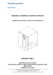
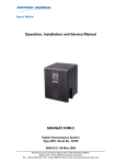
cáÖìêÉ=NJNW
k^sfd^q u jh N=ÜçìëáåÖ
cáÖìêÉ=NJOW
`çåíêçä=~åÇ=Çáëéä~ó=ìåáí
E`arF=Ñêçåí=~åÇ
Ä~Åâ=îáÉï
1
NJO
2
kçK
fíÉã
níóK
1
USB service interface
1
2
Dimmer (CDU display)
1
póëíÉã=lîÉêîáÉï=~åÇ=j~áå=`çãéçåÉåíë
k^sfd^q u jh N
MRSPQPLb
i~ÄÉä=~åÇ=íóéÉ=ä~ÄÉä
The label at the front door shows the power-up sequence and a quick
guide to the operation menu for a single NAVIGAT X MK 1 gyrocompass
system only.
kçíÉ
cáÖìêÉ=NJPW
k^sfd^q u jh N
ä~ÄÉä
NAVIGAT X MK 1
Power-up Sequence
Energize the gyrocompass.
1) System performs self-test.
2) Main PCB status message is shown.
3) Heading display screen is shown.
WARNING
After a cold start, the gyrocompass system
requires a settling time of up to three hours
before reliable heading data is produced.
Operation
>F1 GYRO 1 271.3°
F2 GYRO 1 271.2°
F3 MAGN.C. 270.9°
DIFF G1/M
5° ü
/
MAIN MENU
û
F1 DISPLAY DATA
F2 MANUAL SETTINGS
F3 SETUP MENU
Heading Display Screen
SHIFT+F1: Gyro 1
select heading reference Gyro 1
SHIFT+F2: Gyro 2
select heading reference Gyro 2
SHIFT+F3: Magnetic Compass
select heading reference Mag.
Main Menu Screen
SHIFT+F1: Display Data
select display data screen
SHIFT+F2: Manual Settings
set operating parameters
SHIFT+F3: Setup Menu
access user and service
setup menus
On Alarm:
SHIFT+F1: acknowledge alarm (clears error message
from screen and mutes audible alarm)
SHIFT+RESET: mute audible alarm only
Setting Display Brightness:
Dim+: brighter
Dim–: darker
Selecting Parameters:
/ : show next / previous option
SHIFT+ENTER: confirm input and go to next line
Entering Data:
/ : increase / decrease input value
Dim+ / Dim–: move cursor forward / back
SHIFT+ENTER: confirm input and go to next line
SHIFT+RESET: clear input (value is set to zero)
26789-B
cáÖìêÉ=NJQW
k^sfd^q u jh N
íóéÉ=ä~ÄÉä
póëíÉã=lîÉêîáÉï=~åÇ=j~áå=`çãéçåÉåíë
NJP
MRSPQPLb
k^sfd^q u jh N
j~áå=ÅçãéçåÉåíë
cáÖìêÉ=NJRW
mêáåíÉÇ=`áêÅìáí=_ç~êÇ
Em`_F
2
1
2
2
3
2
2
2
2
2
kçK
fíÉã
níóK
1
Master Printed Circuit Board (PCB)
1
2
Hex head screws
8
3
MK1 housing
1
In figure 1-5 the front door is not shown for better understanding.
NJQ
póëíÉã=lîÉêîáÉï=~åÇ=j~áå=`çãéçåÉåíë
k^sfd^q u jh N
MRSPQPLb
cáÖìêÉ=NJSW
dóêçëéÜÉêÉ=ëìëéÉåëáçå
1
kçK
fíÉã
níóK
1
Gyrosphere suspension
1
In figure 1-6 and 1-7 the PCB is not shown for better understanding.
cáÖìêÉ=NJTW
_~ëÉ=éä~íÉ=~åÇ=ÖóêçJ
ëéÜÉêÉ=ëìëéÉåëáçå
3
1
4
2
kçK
fíÉã
níóK
1
Base plate
1
2
Gyrosphere suspension
1
3
Main power supply transformer (partly covered)
1
4
Sticker of shaft encoder correction angle value
1
póëíÉã=lîÉêîáÉï=~åÇ=j~áå=`çãéçåÉåíë
NJR
MRSPQPLb
k^sfd^q u jh N
NKP aÉëáÖå=~åÇ=j~áå=cÉ~íìêÉë
The NAVIGAT X MK 1 is a microprocessor controlled marine gyrocompass system with integrated automatic North speed error correction.
The NAVIGAT X MK 1 has been type approved by Germanischer Lloyd
(GL), in accordance with the Marine Equipment Directive (MED) 96/98/
EC, as amended, as
gyrocompass (certificate no. 94 418-10 HH),
gyrocompass for high speed craft (HSC) (certificate no. 94 428-10 HH)
and rate of turn indicator (ROTI) (certificate no. 94 424-10 HH).
The NAVIGAT X MK 1 Type 4914 CA complies with the following specified standards as gyrocompass:
IMO resolutions A.424(IX), A.694(17), MCS.191(79), ISO 8728(1997, IEC
60945(2002), IEC 62288(2008) and IEC 61162 series.
The NAVIGAT X MK 1 HSC-version Type 4914 CC (stock no. 74811) with a
specially selected gyrosphere complies with the following specified
standards as gyrocompass for high speed craft (HSC):
IMO resolutions A.821(19), A.694(17), MSC.36(63), MSC.97(73),
MSC.191(79), ISO 16328(2001), IEC 60945(2002), IEC 62288 (2008) and
IEC 61162 series.
The NAVIGAT X MK 1 Type 4914 CA and NAVIGAT X MK 1 HSC-version
Type 4914 CC comply with the following specified standards as rate of
turn indicator (ROTI):
IMO resolutions A.526(13), A.694(17), MSC.36(63), MSC.97(73),
MSC.191(79), ISO 20672(2007), IEC 60945(2002), IEC 62288(2008) and IEC
61162 series.
The NAVIGAT X MK 1 has been type approved by the
Russian River Register (RRR) for the purpose of provision of navigation
safety of inland navigation and river-sea going vessels and has been
assigned certificate 190-06-3.1.1.
For further details see “Marine Equipment Directive EC Declaration of
Conformity” on page 1-14.
The single unit design with a polyurethane hard foam housing allows
the gyrocompass to be installed on any bridge. If required, the operating
unit may be installed at a location remote from the compass or an additional remote operating unit may be used.
The unique method of supporting the gyrosphere by means of mere
buoyancy ensures North stabilisation during short power failures, e.g.,
after a three minute loss of power, no more than two degrees of deviation may be expected. Once power has been restored, the gyrocompass
will return quickly to the correct heading. The combined effects of the
twin rotors and the liquid damping system virtually eliminate latitude
error.
Heading is measured as a 13-bit absolute value with a digital shaft
encoder. The high-speed follow-up system (follow-up speed up to
100°/s) ensures that accurate heading and rate of turn data is provided
under all operating conditions.
Integrated monitoring of the supply powers, gyroscope current and the
follow-up system ensure secure and trouble-free operation.
NJS
aÉëáÖå=~åÇ=j~áå=cÉ~íìêÉë
k^sfd^q u jh N
MRSPQPLb
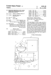
NKQ léÉê~íáåÖ=mêáåÅáéäÉ
The north-seeking element used in the NAVIGAT X MK 1 system is the
gyrosphere, a hermetically sealed unit with a funnel-shaped recess,
reaching from the outer skin down to its centre.
Inside the gyrosphere, two mechanically linked gyroscopes are
mounted with their spin axes horizontal in a carrying frame. The gyroscopes are allowed to turn around the vertical, but torsion bands effect a
defined rest position, while a mechanical linkage ensures that the resultant spin vector of the gyros remains stationary relative to the gyrosphere. This twin gyro arrangement eliminates intercardinal roll error.
Once the gyros have run up to speed, their resultant spin vector, and
with it the gyrosphere, settles in the direction of true North.
cáÖìêÉ=NJUW
dóêçëéÜÉêÉ
damping trough
S gyro
gyro linkage
centering pin
N gyro
gyrosphere shell
The top of the gyrosphere contains an annular damping trough, half
filled with a viscous fluid. The fluid damps azimuthal oscillations of the
gyroscope system. The oscillation period is tuned to the Schuler period
of 84.4 minutes, so that heading errors during horizontal acceleration
due to changes in speed and/or direction are prevented.
The gyrosphere floats in a supporting fluid inside the gyrosphere container. Because the buoyancy of the gyrosphere is a little greater than its
weight, a bearing cup at the bottom of the recess is pressed against the
centering pin and keeps the gyrosphere exactly centered in the container.
In order to make the gyroscope system pendulous, that is, to provide the
gravity controlling moment, the gyrosphere is designed so that its centre of gravity lies slightly below the centre of buoyancy.
The gyroscopes are in fact squirrel-cage induction motors, which attain
a speed of nearly 20000 rpm at a voltage of 100 VAC @ 337 Hz.
In the Mod. 10/3 container, their supply power is applied through the
electrolytically conducting supporting fluid, via the top and bottom contacts. In the Mod. 10/2 and Mod. 7/2 containers, the power is applied via
the centering pin and the bottom contacts.
A follow-up control circuit keeps the container aligned with the gyrosphere at all times, thus heading can be derived from the container’s orientation.
léÉê~íáåÖ=mêáåÅáéäÉ
NJT
MRSPQPLb
k^sfd^q u jh N
While systems with the Mod. 10/3 container employ an optical pick off to
provide the follow-up control signal, systems with the Mod. 10/2 and
Mod. 7/2 containers use a resistance bridge circuit, formed by the conducting paths from the contact pins in the container, through the supporting fluid and to the equator contact of the gyrosphere.
kçíÉ
The Mod. 7/2 container and the Mod. 10/2 container (if not refitted for
mercury free operation) use mercury for the resistance bridge circuit.
Only specially trained personnel is allowed to take care with all handling
of mercury and special handling procedures must be maintained.
Always keep to the current issue of the mercury handling procedures of
Sperry Marine Northrop Grumman, stock no. 026150-0000-000.
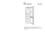
aóå~ãáÅ=eÉ~ÇáåÖ=bêêçê
The adjacent figure 1-9 shows the correlation of dynamic heading error
and latitude of the NAVIGAT X MK 1 System.
cáÖìêÉ=NJVW
aóå~ãáÅ=ÜÉ~ÇáåÖ=Éêêçê
NAVIGAT X MK1 dynamic error
2,5
2
Error (degrees)
1,5
Error
1
0,5
0
0
10
20
30
40
50
60
70
80
90
La!tude (degrees)
Correlation of dynamic heading error and latitude (0.4° x sec. lat.)
NJU
léÉê~íáåÖ=mêáåÅáéäÉ
k^sfd^q u jh N
MRSPQPLb
NKR bñ~ãéäÉ=póëíÉã=`çåÑáÖìê~íáçåë
pí~åÇ~äçåÉ=dóêçÅçãé~ëëLqj`=póëíÉã
As a standalone system, the NAVIGAT X MK 1 provides North-speed
error corrected true heading as well as rate of turn data.
If a fluxgate sensor, type 4863, or an electronic magnetic compass is
installed, the NAVIGAT X MK 1 applies magnetic variation and distributes magnetic compass heading data to external equipment (Transmitting Magnet Compass, TMC function).
The heading difference alarm function permits to monitor the difference
between the gyrocompass and magnetic compass heading sources.
In case of failure of the gyrocompass, the magnetic compass heading
source may be activated to provide an emergency heading reference for
repeaters and other peripheral equipment.
cáÖìêÉ=NJNMW
pí~åÇ~äçåÉ
dóêçÅçãé~ëëLqj`
ëóëíÉã
Ext. Gyrocompass
Magnetic
Compass
Position Receiver
Serial Repeaters
Equipment using
serial input
Equipment using
6 step/ input
Speed Log
ROT
Rudder Angle
Feedback Unit(s)
Status Signals In
Analogue
R.o.T.
Indicators
Nav. Data
Printer
Status Signals Out
bñ~ãéäÉ=póëíÉã=`çåÑáÖìê~íáçåë
NJV
MRSPQPLb
k^sfd^q u jh N
aì~ä=k^sfd^q u jh N=dóêçÅçãé~ëëLqj`=póëíÉã
The system shown in figure 1-11 below is the standard configuration for
a dual NAVIGAT X MK 1 gyrocompass system.
In addition to the two NAVIGAT X MK 1 gyrocompasses, this system
comprises the NAVITWIN IV heading management system (HMS) and
the Switch-Over Unit Type 4932.
By selecting the active heading source at the NAVITWIN IV, the operator
determines which gyrocompasses’ data is distributed via the SwitchOver Unit to external equipment, such as heading control systems,
RADAR, compass repeaters etc.
The NAVITWIN’s heading diff. alarm function permits to monitor the difference between any two of the available heading sources. The off heading alarm function permits to monitor the difference between the actual
heading from the active source and the set heading order, as received
from a heading control system or entered manually.
Alarms generated locally by a NAVIGAT gyrocompass are indicated and
may be acknowledged at the NAVITWIN IV. In turn, the NAVITWIN IV
transmits system-wide operational settings and setup parameters to the
NAVIGAT gyrocompasses. The available heading sources, the current
source selection and the heading difference alarm threshold (hdg. diff.
threshold) are also indicated at both gyrocompasses.
If a magnetic compass heading source is installed, the NAVITWIN
applies magnetic variation and distributes the data to external equipment (TMC function). In case of failure of the gyrocompasses, the magnetic compass heading source may be activated to provide an
emergency heading reference for repeaters and other peripheral equipment.
cáÖìêÉ=NJNNW
k^sfd^q=aì~ä
dóêçÅçãé~ëë=póëíÉã
Switch-Over Unit
G1
G1 Hdg.
G/ M Headings,
RoT, and all other
data/signals
distributed via
Switch-Over Unit
G2
G2 Hdg.
M Hdg.
M
GYRO
1
246.8
GYRO
2
246.7
MAGN
COMP
247.0
Source Sel.
Status
Alarm Status
(Hdg. Diff, Off Hdg)
NAVITWIN IV
kçíÉ
NJNM
A system with one NAVIGAT X MK 1 and one NAVIGAT 2100 / NAVIGAT
3000 fiber-optic gyrocompass is also possible in an otherwise identical
configuration.
bñ~ãéäÉ=póëíÉã=`çåÑáÖìê~íáçåë
k^sfd^q u jh N
MRSPQPLb
NKS qÉÅÜåáÅ~ä=a~í~
^ÅÅìê~ÅáÉë
heading:
linear mean settle point error
static heading error
≤ 0.1° x secant latitude
≤ 0.1° x secant latitude
dynamic heading error* (range of operation
within 70° S to 70° N latitude)
≤ 0.4° x secant latitude
deviation after 3 min. power interruption
< 2°
rate of turn
≤ 0.5°/minute
*The correlation of dynamic heading error and latitude is shown in
figure 1-9 on page 1-8
léÉê~íáçå~ä=`Ü~ê~ÅíÉêáëíáÅë
mean setting time
<3h
max. follow-up speed
100°/s
freedom of roll and pitch
- with container Mod. 10
- with container Mod. 7
± 40°
± 90°
mean time between failure (MTBF)
40 000 h
båîáêçåãÉåí~ä=oÉèìáêÉãÉåíë
ambient temperature, operation
- 10 to + 55° C
ambient temperature, storage
(without supporting fluid)
- 25 to + 70° C
environmental conditions / EMC
in accordance with IEC 60945
mêçíÉÅíáçå=dê~ÇÉ
according to IEC 60529/DIN 40050
IP 23
j~ÖåÉíáÅ=`äÉ~ê~åÅÉ
to standard magnetic compass
0.6 m
to steering magnetic compass
0.4 m
reduced, to standard magnetic compass
0.3 m
reduced, to steering magnetic compass
0.3 m
mçïÉê=pìééäó
qÉÅÜåáÅ~ä=a~í~
supply voltage
main: 115/230 VAC, 50/60 Hz;
backup: 24 VDC (18-36 V), including automatic switch over to
backup supply in case of main
supply failure
max. ripple content DC supply
± 4 Vpp; extreme values may not
exceed 36 V or fall below 18 V
NJNN
MRSPQPLb
k^sfd^q u jh N
mçïÉê=pìééäó
power consumption:
start-up
operation
each analogue repeater
each digital repeater
AC: 125 VA; DC: 80 W
AC: 75 VA; DC: 45 W
AC: 7 VA; DC: 7 W
AC: 5 VA; DC: 5 W
aáãÉåëáçåë=~åÇ=tÉáÖÜí
width
404 mm
height
520 mm
depth
420 mm
520
420
404
weight
25 kg approx.
a~í~=fåéìíë
external gyro heading
NMEA 0183 / IEC 61162-1
or PLATH protocol
or Lehmkuhl (1200, 2400, 4800 or
9600 Bd.)
magnetic compass heading
NMEA 0183 / IEC 61162-1
or PLATH protocol
or NAVIPILOT
position
NMEA 0183 / IEC 61162-1
speed
NMEA 0183 / IEC 61162-1
compass monitor NAVITWIN
(Heading Management System)
NMEA 0183 / IEC 61162-1
páÖå~ä=~åÇ=pí~íìë=fåéìíë
NJNO
magnetic compass heading,
fluxgate sensor
sine, cosine and reference (ref.)
voltages from Sperry Marine fluxgate sensor type 4863
speed, 200 pulse/nm
connection to power ground
(P.Gnd) via external contact,
momentary
rudder angle feedback unit
(2x; reads rudder angle for output
to NAVIPRINT)
0 – 5 VDC return voltage from
feedback potentiometer
steering mode status (auto/man)
connection to P.Gnd via ext. contact, latching
external heading reference selection. (gyro1/gyro2)
connection to P.Gnd via ext. contact, latching
external heading reference selection. (gyro/mag)
connection to P.Gnd via ext. contact, latching
qÉÅÜåáÅ~ä=a~í~
k^sfd^q u jh N
MRSPQPLb
páÖå~ä=~åÇ=pí~íìë=fåéìíë
external alarm acknowledge
(mute)
connection to P.Gnd via ext. contact, momentary
status input port (log status or
heading +180° function)
connection to P.Gnd via ext. contact, latching
a~í~=lìíéìíë
serial repeater outputs
(12x TTL)
NMEA 0183
sensor data outputs
(4x RS-422; 3 available if AD10
output active)
NMEA 0183 / IEC 61162-1
FAST output
(1x RS-422)
NMEA 0183 / IEC 61162-1
or PLATH protocol
(update rate 20 Hz)
SuperFAST output
(2x RS-422; 1 available if AD10
output active)
NMEA 0183 / IEC 61162-1
or NMEA 0183 / IEC 61162-2
or PLATH protocol
(update rate 20 Hz)
AD10 heading data output
AD10 serial data and clock
NAVITWIN output
NMEA 0183 / IEC 61162-1
to external gyro / compass monitor NAVITWIN
NAVIPRINT output
serial data to nav. data printer
páÖå~ä=~åÇ=pí~íìë=lìíéìíë
qÉÅÜåáÅ~ä=a~í~
6 step/° output (2 x)
3 phases, switched to 0 V potential if active („minus switching“),
common positive;
internal supply 24 VDC
max. 18 W
(12 – 70 VDC phase voltage when
ext. power supply is used)
rate of turn, analogue
± 0.1 – 999.9 mV/°/min;
max. 10 V, 10 mA
power failure/general alarm
heading difference alarm
max. ROT exceeded alarm,
heading source selection status
status out to switch-over unit
watch alarm acknowledge
AC power status
DC power status
potential-free contact closures,
each rated
30 VDC/1.0 A,
100 VDC/0.3 A,
125 VAC/0.5 A
NJNP
MRSPQPLb
k^sfd^q u jh N
NKT j~êáåÉ=bèìáéãÉåí=aáêÉÅíáîÉ=b`=aÉÅä~ê~íáçå=çÑ=`çåJ
Ñçêãáíó
aÉÅä~ê~íáçåW=
Northrop Grumman Sperry Marine B.V.
Woltmanstrasse 19
D-20097 Hamburg, Germany.
as manufacturer hereby declares that the following specified equipment:
“NAVIGAT X MK1 GYROCOMPASS SYSTEM”
complies with the Marine Equipment Directive 96/98/EC, as amended.
This equipment has been tested to verify compliance with the
Regulations and Testing Standards as per EC Type Examination (B) and
EC Quality System (D) issued by:
Notified Body No. 0098 Germanischer Lloyd.
kçíÉ
The current issue of the detailed Marine Equipment Directive EC Declaration of Conformity of Northrop Grumman Sperry Marine B.V. Hamburg
is part of the client CD stock no. 56 800.
For further details please contact:
Northrop Grumman Sperry Marine B.V. Hamburg
Regulatory Support Group
NJNQ
j~êáåÉ=bèìáéãÉåí=aáêÉÅíáîÉ=b`=aÉÅä~ê~íáçå=çÑ=`çåJ
k^sfd^q u jh N
MRSPQPLb
`Ü~éíÉê=OW léÉê~íáçå
OKN léÉê~íáåÖ=`çåÇáíáçåë
The permitted ambient temperature for the operation of the gyrocompass system is between - 10° C to + 55° C.
`^rqflk
Risk of damage/destruction through low temperatures
The supporting fluid in the gyrosphere container will start freezing at
temperatures below 0° C.
The NAVIGAT X MK 1 must no longer be operated when the ambient temperature at the gyrocompass’ location falls below - 10° C while the compass is in operation or when the ambient temperature falls below 0° C
while the gyrocompass is not in operation.
Always make sure, that the ambient temperature is higher than 0° C
respective 10° C. If this is not possible, the gyrosphere container with
gyrosphere must be removed from the NAVIGAT X MK 1 and transported
to a place with sufficient ambient temperature.
Make sure to remove the gyrosphere from the gyrosphere container if no
place with sufficient ambient temperature is available to eliminate damage from freezing supporting fluid.
When the ambient temperature at the gyrocompass’ location falls below
- 10° C while the compass is in operation or when the ambient temperature falls below 0° C while the compass is not in operation, the gyrosphere container must be removed from the compass housing and
stored in a place where the ambient temperature will not fall below 0° C.
For the service procedure to remove the gyrosphere container from the
compass housing see “Removing the Gyrosphere Container from the
Compass Housing” on page 5-2.
kçíÉ
Always be aware, that in case no storage place is available where the
ambient temperature will not fall below 0° C, the gyrosphere must be
removed by authorized service personnel from the gyrosphere container to prevent possible damage by frozen supporting fluid.
`^rqflk
kçíÉ
léÉê~íáåÖ=`çåÇáíáçåë
Risk of damage through unauthorized service
Only authorized service personnel is allowed to remove the gyrosphere
from the gyrosphere container.
Always keep to the mandatory safety requirements and the correct service work procedure to remove the gyrosphere from the gyrosphere container.
For installation and service procedures of the gyrosphere and gyrosphere container, the following separate Installation, Maintenance and
Service Procedures, delivered with the gyrosphere, apply:
- 04911-0125-001, for gyrosphere type 2, gyrosphere container mod. 7/2
- 04911-0125-002, for gyrosphere type 2, gyrosphere container mod. 10/2
- 05000-0125-001, for gyrosphere type 3, gyrosphere container mod. 10/3.
OJN
MRSPQPLb
k^sfd^q u jh N
OKO aáëéä~ó=~åÇ=léÉê~íáåÖ=hÉóë
`çåíêçä=~åÇ=aáëéä~ó=råáí=E`arF
cáÖìêÉ=OJNW
k^sfd^q u jh N
Åçåíêçä=~åÇ=Çáëéä~ó=ìåáí
1
ÿÿÿÿÿÿÿÿÿÿÿÿÿÿÿÿÿÿÿÿ
ÿÿÿÿÿÿÿÿÿÿÿÿÿÿÿÿÿÿÿÿ
ÿÿÿÿÿÿÿÿÿÿÿÿÿÿÿÿÿÿÿÿ
ÿÿÿÿÿÿÿÿÿÿÿÿÿÿÿÿÿÿÿÿ
3
2
4
6
5
7
aáëéä~ó
1 i`a=aáëéä~óW=4x20 character text display.
•
In normal operational mode: shows the available heading
sources and the heading difference alarm threshold.
•
In menu mode: displays the currently active operating menu
screen.
léÉê~íáåÖ=hÉóë
2 jbkr=L=cN=âÉóW=Calls up the main menu from normal operational
mode. When pressed in menu mode, returns to next higher menu
level.
When pressed simultaneously with the=pefcq=key, the cN function is
executed.
3 ré=EûF=L=cO=âÉóW=In menu mode, returns from the main menu to normal operational mode. Within a sub-menu, scrolls up through available pages on same menu level.
When pressed simultaneously with the=pefcq=key, the cO function is
executed.
4 açïå=EüF=L=cP=âÉóW=Calls up the Main Menu from normal operational
mode. Within a sub-menu, scrolls down through available pages on
same menu level.
When pressed simultaneously with the=pefcq=key, the cP function is
executed.
5 pefcq=âÉóW=Pressed with other key to call up key’s pefcq function.
6 afjH=L=obpbq=âÉóW=Adjust the display brightness.
When pressed simultaneously with the=pefcq key, the obpbq function
is executed.
7 afjJ=L=bkqbo=âÉóW=Adjust the display brightness.
When pressed simultaneously with the=pefcq key, the bkqbo function is executed.
OJO
aáëéä~ó=~åÇ=léÉê~íáåÖ=hÉóë
k^sfd^q u jh N
MRSPQPLb
OKP bñíÉêå~ä=`çåíêçä=aÉîáÅÉë
Depending on the installation, external devices may be present which
remotely control certain functions of the NAVIGAT X MK 1:
bñíÉêå~ä=`çåíêçä=aÉîáÅÉë
•
bñíÉêå~ä=ÇÉîáÅÉW An external device may be used to select the
“active” source, i.e. the heading reference to be distributed to compass repeaters, heading control system, RADAR, ECDIS etc.
•
bñíÉêå~ä=ëÉäÉÅíçêW An external selector switch may be used to reverse
the heading (apply a 180° offset to the heading data), e.g. for operation in double-ended ferries.
•
oÉãçíÉ=ÇÉîáÅÉW The audible alarm at the NAVIGAT X MK 1 may be
muted from a remote device, e.g. a central alarm panel.
OJP
MRSPQPLb
k^sfd^q u jh N
OKQ mçïÉêJìé=pÉèìÉåÅÉ
t^okfkd
iáãáíÉÇ=ÜÉ~ÇáåÖ=Ç~í~=~ÅÅìê~Åó=ÇìêáåÖ=ëÉííäáåÖ=íáãÉ
^ÑíÉê=~=éçïÉêJìé=Ñêçã=ÅçäÇI=íÜÉ=k^sfd^q u jh N=êÉèìáêÉë=~=ëÉííäáåÖ=íáãÉ=
çÑ=íÜêÉÉ=Üçìêë=ÄÉÑçêÉ=êÉäá~ÄäÉ=ÜÉ~ÇáåÖ=Ç~í~=áë=~î~áä~ÄäÉK
mçïÉê=ìé=íÜÉ=ëóëíÉã=~í=äÉ~ëí=íÜêÉÉ=Üçìêë=ÄÉÑçêÉ=äÉ~îáåÖ=Ü~êÄçìêK
mçïÉê=Ççïå=íÜÉ=ëóëíÉã=ÇìêáåÖ=äçåÖ=ÇçÅâáåÖ=éÉêáçÇë=çåäóK
j~âÉ=ëìêÉ=íÜ~í=íÜÉ=k^sfd^q u jh N=Ü~ë=ëÉííäÉÇ=ÄÉÑçêÉ=ìëáåÖ=áíë=ÜÉ~ÇáåÖ=
~ë=íÜÉ=êÉÑÉêÉåÅÉ=Ñçê=ÜÉ~ÇáåÖ=Åçåíêçä=ëóëíÉãëI=o^a^oI=b`afpI=ÉíÅK
^=ã~ÖåÉíáÅ=Åçãé~ëë=ÜÉ~ÇáåÖ=ëçìêÅÉ=ëÜçìäÇ=ÄÉ=ëÉäÉÅíÉÇ=~ë=êÉÑÉêÉåÅÉ=
çåäó=áå=Å~ëÉ=çÑ=Ñ~áäìêÉ=çÑ=íÜÉ=ÖóêçÅçãé~ëëEÉëFK
The NAVIGAT X MK 1 is not equipped with a power switch. The gyrocompass powers up as soon as supply power is applied.
Upon power-up, the startup routine is executed:
SPERRY
MARINE
A startup screen is shown and a system
test sequence is executed.
NAVIGAT X MK 1
>F1 GYRO 1
F2 GYRO 2
F3 MAGN.C.
DIFF G1/G2
271.2°
271.4°
270.9°
5°ü
When the system test has been passed, the
NAVIGAT X MK 1 enters normal operational
mode. The display shows the heading data
from the available compasses and the
heading difference alarm threshold.
The currently active heading source is indicated by an arrow symbol (>) next to the
source’s name.
The label at the front door shows a short overview of the power-up
sequence with a belonging Warning note for a single NAVIGAT X MK 1
gyrocompass system.
kçíÉ
cáÖìêÉ=OJOW
mçïÉêJìé=pÉèìÉåÅÉ
k^sfd^q u jh N
ä~ÄÉä
OJQ
mçïÉêJìé=pÉèìÉåÅÉ
k^sfd^q u jh N
MRSPQPLb
OKR pÉäÉÅíáåÖ=íÜÉ=^ÅíáîÉ=eÉ~ÇáåÖ=pçìêÅÉ
t^okfkd
iáãáíÉÇ=ÜÉ~ÇáåÖ=Ç~í~=~ÅÅìê~Åó=ÇìêáåÖ=ëÉííäáåÖ=íáãÉ
^ÑíÉê=~=éçïÉêJìé=Ñêçã=ÅçäÇI=íÜÉ=k^sfd^q u jh N=êÉèìáêÉë=~=ëÉííäáåÖ=íáãÉ=
çÑ=íÜêÉÉ=Üçìêë=ÄÉÑçêÉ=êÉäá~ÄäÉ=ÜÉ~ÇáåÖ=Ç~í~=áë=~î~áä~ÄäÉK
mçïÉê=ìé=íÜÉ=ëóëíÉã=~í=äÉ~ëí=íÜêÉÉ=Üçìêë=ÄÉÑçêÉ=äÉ~îáåÖ=Ü~êÄçìêK
mçïÉê=Ççïå=íÜÉ=ëóëíÉã=ÇìêáåÖ=äçåÖ=ÇçÅâáåÖ=éÉêáçÇë=çåäóK
j~âÉ=ëìêÉ=íÜ~í=íÜÉ=k^sfd^q u jh N=Ü~ë=ëÉííäÉÇ=ÄÉÑçêÉ=ìëáåÖ=áíë=ÜÉ~ÇáåÖ=
~ë=íÜÉ=êÉÑÉêÉåÅÉ=Ñçê=ÜÉ~ÇáåÖ=Åçåíêçä=ëóëíÉãëI=o^a^oI=b`afpI=ÉíÅK
^=ã~ÖåÉíáÅ=Åçãé~ëë=ÜÉ~ÇáåÖ=ëçìêÅÉ=ëÜçìäÇ=ÄÉ=ëÉäÉÅíÉÇ=~ë=êÉÑÉêÉåÅÉ=
çåäó=áå=Å~ëÉ=çÑ=Ñ~áäìêÉ=çÑ=íÜÉ=ÖóêçÅçãé~ëëEÉëFK
The operator may select one of the available heading sources as the
“active” source, i.e. the heading reference to be distributed to compass
repeaters, heading control system, RADAR, ECDIS etc.
Depending on the system configuration, the active heading source is
either selected from the NAVIGAT X MK 1 control and display unit (single or dual gyrocompass systems) or from an external device such as a
NAVITWIN compass monitor/heading management system,
a NAVIPILOT heading control system or an external selector switch.
>F1 GYRO 1
F2 GYRO 2
F3 MAGN.C.
DIFF G1/G2
271.2°
271.4°
270.9°
5°ü
To change the active heading source from
the control and display unit:
•
Press the selector key next to the
desired source’s heading display.
⇒ The selected source is made active.
F1 GYRO 1
>F2 GYRO 2
F3 MAGN.C.
DIFF G1/G2
kçíÉ
271.2°
271.4°
270.9°
5°ü
If the system is configured for source selection from an external device,
selection from the control and display unit is disabled.
The active heading source can be changed in a manual steering mode
only.
In automatic steering modes, source selection is disabled and an error
beep sounds when an attempt is made to change the active source.
pÉäÉÅíáåÖ=íÜÉ=^ÅíáîÉ=eÉ~ÇáåÖ=pçìêÅÉ
OJR
MRSPQPLb
k^sfd^q u jh N
OKS ^ÇàìëíáåÖ=íÜÉ=aáëéä~ó=_êáÖÜíåÉëë
The brightness of the display and keypad illumination is adjusted via the
afjHLafjJ=keys:
•
>F1 GYRO 1
F2 GYRO 2
F3 MAGN.C.
F3
DIFF
MAGN.C.
G1/G2
271.2°
271.2
271.4°
271.4
270.9°
270.9
270.9°
5
Press the afjH=key.
⇒ The illumination brightness is
increased.
•
Press the afjJ key.
⇒ The illumination brightness is reduced.
⇒ Additional dimmer functionality can be applied by usage of the dimmer at the backside of the CDU, see “CDU display dimmer settings”
on page 6-4 for details.
OKT léíáçå~ä=cìåÅíáçåë
The following functions may be available if the system is equipped with
the respective external controls and configured accordingly.
jìíáåÖ=^ä~êãë=oÉãçíÉäó
On alarm, actuate the mute control at a remote device (e.g. a central
alarm panel). The audible alarm is muted.
kçíÉ
A remotely muted alarm remains in the pending (unacknowledged) state.
The alarm message is shown on the display until the alarm is acknowledged at the NAVIGAT X MK 1 or the cause of the alarm is eliminated.
oÉîÉêëáåÖ=íÜÉ=eÉ~ÇáåÖ=aáëéä~ó=ENUMø=çÑÑëÉíF
To reverse the heading display, e.g. for operation on double-ended ferries, activate the 180° offset function at the associated external control.
kçíÉ
The heading display may be reversed automatically in some installations, e.g. when control is centrally transferred between fore and aft
steering stands.
oÉëÉííáåÖL^ÅâåçïäÉÇÖáåÖ=~=`Éåíê~ä=t~íÅÜ=^ä~êã
If connected to a central watch alarm facility ('dead man alarm'), the
NAVIGAT X MK 1 will automatically reset the watch alarm timer whenever a key is pressed on the unit.
Should a watch alarm be given, pressing any key at the NAVIGAT X MK 1
will acknowledge the alarm and reset the watch alarm timer.
OJS
^ÇàìëíáåÖ=íÜÉ=aáëéä~ó=_êáÖÜíåÉëë
k^sfd^q u jh N
MRSPQPLb
OKU léÉê~íáåÖ=jÉåì
The data display menu as well as the manual settings, user and service
setup sub-menus are accessed through a multilevel operating menu.
båíÉêáåÖ=~åÇ=nìáííáåÖ=íÜÉ=j~áå=jÉåì
>F1 GYRO 1
F2 GYRO 2
F3 MAGN.C.
DIFF G1/G2
From the normal operational mode,
press the jbkr or the açïå key to
enter the menu mode.
271.2°
271.4°
270.9°
5°ü
The main menu screen opens.
From the main menu screen, press the
ré key to return to the normal operational mode.
MAIN MENU
û
F1 DISPLAY DATA
F2 MANUAL SETTINGS
F3 SETUP MENU
The NAVIGAT X MK 1 returns to normal operational mode.
k~îáÖ~íáåÖ=íÜÉ=jÉåì
In the menu mode, the operator may navigate through the menu using
the cNI=cOI=cPI=réLaçïåI=aáãHLaáãJ=and jbkr key functions.
Press pÜáÑíJcN, pÜáÑíJcO or
pÜáÑíJcP to go to the respective sub-menu.
MENU X
F1 SUBMENU Y
SUBMENU Y
OPTION A1
OPTION A2
OPTION A3
ü
SUBMENU Y
OPTION B1
OPTION B2
OPTION B3
û
SUBMENU Y
OPTION C1
û
SUBMENU Y
OPTION A1
ü
Arrow symbols (û/ü) at the
right of the window indicate
that further pages are available at the same menu level.
With the açïå or ré key,
scroll to the next or previous
page respectively.
Press the jbkr key to return
to the next higher menu
level.
MENU X
F1 SUBMENU Y
léÉê~íáåÖ=jÉåì
OJT
MRSPQPLb
k^sfd^q u jh N
pÉäÉÅíáåÖ=m~ê~ãÉíÉê=pÉííáåÖë
A number of operational and setup parameters are set by selecting the
appropriate option from a list.
Flashing up/down arrow symbols to the right of a parameter setting
indicate that a selection can be made from a list of options:
MAN.SETTINGS
SPEED MODE: AUTO ý
POSIT MODE: AUTO
1. With the réLaçïå keys, select the
required option.
•
Press pÜáÑíJbkqbo to confirm and store
the selection.
•
jbkr leaves the sub-menu without
changes.
bÇáíáåÖ=m~ê~ãÉíÉê=s~äìÉë
A number of operational and setup parameters are set by editing a
numerical value.
A flashing box cursor indicates that a parameter’s value is editable:
MAN.SETTINGS
MAN SPEED: ÿ2.3 kn
MAN LAT: 56:78.90 N
OJU
1. With the réLaçïå keys, edit the character at the current cursor position.
2. With the aáãHLaáãJ arrow keys, move
the cursor forward/back to edit the
next/previous character.
•
Press pÜáÑíJbkqbo to confirm and store
the new value.
•
jbkr leaves the sub-menu without
changes.
léÉê~íáåÖ=jÉåì
k^sfd^q u jh N
MRSPQPLb
OKV pÉäÉÅíáåÖ=~=aáëéä~ó=a~í~=m~ÖÉ
The Display Data menu allows the operator to select one out of five
pages to permanently display relevant operational data, instead of the
normal heading display screen.
The selected page is displayed until another page is selected or the Display Data mode is quit.
MAIN MENU
F1 DISPLAY DATA
F2 MANUAL SETTINGS
F3 SETUP MENU
DISPLAY DATA GYRO 1
HEADING TRUE 271.3
ROT
1.2 /MIN
CORR. ON
0.2
DISPLAY DATA GYRO 1
HEADING MAGN 270.9
MAGN.VAR.
2.3 E
DISPLAY DATA GYRO 1
POSITION AUTO
LAT 44.09.46 N
LON 023.54.21 E
DISPLAY DATA GYRO 1
SPEED AUTO
12.3 kn
CORR. 12.3 kn
DISPLAY DATA GYRO 1
DATE 23.01.06
TIME 12:34
pÉäÉÅíáåÖ=~=aáëéä~ó=a~í~=m~ÖÉ
1. From the Main Menu, press
pefcq=J=cN to go to the Display
Data sub-menu.
2. With the réLaçïå keys, select
the required page to display.
The following data pages are
available:
•
HEADING TRUE = True heading (own gyro heading);
ROT = Rate of turn;
CORR. = Correction mode and
value.
•
HEADING MAGN = Magnetic
compass heading;
MAGN. VAR.: Magnetic variation.
•
Position Mode;
LAT = Latitude
LON = Longitude (in auto
mode).
•
Speed Mode;
Actual speed value
CORR. = Speed value used for
speed error correction.
•
DATE = Date (DD.MM.YY);
TIME = Time (hh.mm).
OJV
MRSPQPLb
k^sfd^q u jh N
OKNM j~åì~ä=pÉííáåÖë=jÉåì
The Manual Settings menu provides access to settings which the operator may need to alter more or less frequently during normal operation.
kçíÉ
In case a NAVITWIN compass monitor / heading management system is
installed, the manual settings must be entered at the NAVITWIN.
The NAVITWIN will overwrite any manual settings entered locally at the
NAVIGAT X MK 1 control and display unit.
`~éíáçå=Ñçê=pÉäÉÅíáåÖ=~åÇ=bÇáíáåÖ
Figure 2-3 shows the caption for the different selecting and editing symbols used in all manual setting figures.
cáÖìêÉ=OJPW
`~éíáçå=Ñçê=ÅÜçáÅÉI
ëÉäÉÅíáåÖ=~åÇ=ÉÇáíáåÖ
SERVICE SETUP 1 û
F1 SUBMENU 1
F2 SUBMENU 2
F3 SUBMENU 3
ü
SUBMENU 1
functionality of submenu 1
Choice =“A” OR “B”
CHOICE A
CHOICE B
SUBMENU 2
SELECTION A
SELECTION B
SELECTION C
functionality of submenu 2
SUBMENU 3
functionality of submenu 3
Cumulative Selection =
“A” and/or ”B” and/or “C”
EDITING OF NUMERIC
VALUES e.g.: 0,1 – 9,9 sec
kçíÉ
OJNM
Editing with: ûü / +-
`ÜçáÅÉ means that either “A” or “B” must be chosen.
pÉäÉÅíáçå means that “A” and/or “B” can be selected cumulatively.
bÇáíáåÖ=means that numeric values must be edited.
j~åì~ä=pÉííáåÖë=jÉåì
k^sfd^q u jh N
MRSPQPLb
j~åì~ä=pÉííáåÖë=Ó=lîÉêîáÉï
cáÖìêÉ=OJQW
j~åì~ä=pÉííáåÖë
MAN.SETTINGS GYRO 1
F1 SPEED/LATITUDE
F2 HDG DIFF. ALARM
F3 MAG. VARIATION ü
speed/latitude input settings
SPEED/LATITUDE
F1 SPEED/LAT MODE
SPEED MODE:
AUTO
MAN
POSIT MODE:
AUTO
MAN
F2 SPEED/LAT SET
MAN SPEED:
0.0 – 99.9 kts.
MAN LAT: 99:99.99 N – 99:99.99 S
HDG DIFF. ALARM
heading difference alarm threshold
BETWEEN:
GY1/GY2
GY1/MAG
GY2/MAG
OFF
DIFF. ALARM: 0 – 99°
MAGNETIC VARIATION
mag. variation input settings
MODE:
AUTO
MAN
MAN. VALUE: 99.9° W – 99.9° E
contd. on next page
j~åì~ä=pÉííáåÖë=jÉåì
OJNN
MRSPQPLb
cáÖìêÉ=OJRW
j~åì~ä=pÉííáåÖë
EÅçåíÇKF
k^sfd^q u jh N
contd. from previous page
MAN.SETTINGS GYRO 1û
F1 NORTH SP.ERR.CORR
F2 SET.NAVIPRINT
F3 SETTINGS ROT
ü
NORTH SP. ERR. CORR
north speed error correction
ON
OFF
nav. data printer settings
SET. NAVIPRINT
NAVIPRINT
ON
OFF
PAP. SPEED
60 mm
150 mm
600 mm
HDG
±30°
±180°
RUDDER
±9°
±45°
±70°
OFF
rate of turn time constant
MAN. SETTINGS
F1 TIME CONST. ROT
TIME CONST. FOR
ANALOG ROT OUTPUT
0.0 – 10.0 sec
F2 MAX. VALUE ROT
MAXIMUM VALUE
RATE OF TURN
0 – 9999 °/min
OJNO
j~åì~ä=pÉííáåÖë=jÉåì
k^sfd^q u jh N
MRSPQPLb
j~åì~ä=pÉííáåÖë=Ó=m~ê~ãÉíÉêë
pmbbaLi^qfqrab
pmbbaLi^q=jlab
Selects the speed and position input modes.
pmbba=jlab
Selects the speed input mode.
Settings:
^rql
Speed data is read automatically from the serial data or the
200 pulse/nm input
j^k
The actual speed value is entered manually
mlpfq=jlab
Selects the position input mode.
Settings:
^rql
Position data is read automatically from the serial data input
j^k
The actual position is entered manually
pmbbaLi^q=pbq
Sets the manual input values for the speed and latitude.
Settings:
j^k=pmbba
For setting the manual speed input value
j^k=i^q
For setting the manual position input value
Values:
j~åì~ä=pÉííáåÖë=jÉåì
speed: MKM=Ó=VVKV âå
latitude: VMøMMKMMÛ=k=Ó=VMøMMKMMÛ=p
OJNP
MRSPQPLb
k^sfd^q u jh N
eadK=afccK=^i^oj=EeÉ~ÇáåÖ=aáÑÑÉêÉåÅÉ=^ä~êãF
Sets the manual input values for the heading difference alarm threshold.
_bqtbbk
Selects the heading sources to monitor.
Settings:
dvNLdvO
Monitor difference between gyros 1 and 2 heading
dvNLj^d
Monitor difference between gyro 1 and magnetic compass
heading
dvOLj^d
Monitor difference between gyro 2 and magnetic heading.
lcc
Heading difference alarm monitoring is disabled
afccK=^ä~êã=EeÉ~ÇáåÖ=aáÑÑÉêÉåÅÉ=^ä~êã=íÜêÉëÜçäÇF
Sets the alarm threshold value.
Value:
M=Ó=VVø
j^dkbqf`=s^of^qflk
Sets the magnetic variation input parameters.
jlab
Selects the magnetic variation input mode.
Settings:
^rql
Magnetic variation data is read automatically
j^k
The actual magnetic variation value is entered manually
j^k=s^irb=Eã~åì~ä=î~äìÉF
Sets the manual input value for the magnetic variation.
Value:
99.9° W – 99.9° E
kloqe=pmK=booK=`looK=EkçêíÜ=péÉÉÇ=bêêçê=`çêêÉÅíáçåF
Selects the North speed error correction mode.
Settings:
lk
Automatic North speed error correction is enabled.
lcc
Automatic North speed error correction is disabled.
OJNQ
j~åì~ä=pÉííáåÖë=jÉåì
k^sfd^q u jh N
MRSPQPLb
pbqK=k^sfmofkq
Sets the operating parameters for the NAVIPRINT navigation data
printer.
k^sfmofkq
Turns printing on and off.
Settings:
lk
Activate output to printer
lcc
No output to printer
m^mK=pmbba=Eé~éÉê=ëéÉÉÇF
Sets the paper feed speed.
Settings:
SM ãã
print at 60 mm/h (1 cm = 10 min.).
NRM ãã
print at 150 mm/h (1 cm = 4 min.)
SMM ãã
print at 600 mm/h (1 cm = 1 min.)
ead=EÜÉ~ÇáåÖF
Sets the scaling of the heading graph.
Settings:
œ PM
scale to show 30° to the left and to the right from the
graph’s centre (current print position shifts to centre when
graph reaches margin)
œ NUMø
scale to show 180° to the left and to the right from the
graph’s centre (current print position shifts to the centre
when graph reaches margin)
j~åì~ä=pÉííáåÖë=jÉåì
OJNR
MRSPQPLb
k^sfd^q u jh N
oraabo
Sets the scaling of the rudder angle graph.
Settings:
œ Vø
scale to show 9° to the left and to the right from the graph’s
centre. This setting provides a high-resolution recording of
small rudder movements and is useful for monitoring e.g.
the steering behaviour of an autopilot.
œ QRø
scale to show ± 45°. Standard setting for ± 45° steering
gears.
œ TMø
scale to show ± 70°. Standard setting for ± 70° steering
gears.
lcc
do not print rudder angle graph. Required setting if no rudder angle feedback unit is connected to the compass.
j^kK=pbqqfkdp=Eã~åì~ä=olq=ëÉííáåÖëF
Sets the parameters for the analog rate of turn output.
`^rqflk
kçíÉ
Risk of ineffective manual ROT damping settings
The selected ROT damping time constant for the analogue ROT output in
the manual settings menu needs additional activation to become effective by means of a wire link installed at the master PCB TB2 19/20.
To make sure, that the ROT damping time constant setting for the analogue ROT output becomes effective, check if the mandatory wire link
between the master PCB TB2 19/20 is correctly installed.
qfjb=`lkpqK=olq=L=qfjb=`lkpqK=clo=^k^ild=olq=lrqmrq
Sets the ROT damping time constant value for the analogue rate of turn
output. The larger the time constant, the less short-time fluctuations will
be present in the analogue rate of turn output voltage.
Value:
MKM=Ó=NMKM ëÉÅ
Typical values are generally between 2 to 4 sec. (only effective if wire link TB2 19/20 at the master PCB is installed)
kçíÉ
Following IMO requirements, the ROT damping time constant value for
the analogue rate of turn output can be selected between 0.0 to 10.0 sec.
All selected values above 10.0 sec will not be accepted by the menu and
„ERR“ is displayed for showing that the selected value is not valid.
j^uK=s^irb=olq=L=j^ufjrj=s^irb=o^qb=lc=qrok
Sets the alarm threshold for the “Max. Rate of Turn exceeded” alarm.
Value:
OJNS
MKM=Ó=SMMM=øLãáåK
j~åì~ä=pÉííáåÖë=jÉåì
k^sfd^q u jh N
MRSPQPLb
OKNN rëÉê=pÉíìé
The User Setup menu provides access to settings which the operator
may need to alter occasionally.
To access the User Setup:
MAIN MENU
û
F1 DISPLAY DATA
F2 MANUAL SETTINGS
F3 SETUP MENU
SETUP MENU
F1 USER SETUP
F2 SERVICE SETUP
Call up the Main Menu
Press Shift-F3 to select "Setup Menu".
Press Shift-F1 to select "User Setup".
The User Setup sub-menu opens.
USER SETUP
F1 DATE/TIME
F2 SOFTWARE VERSION
F3 MAG.C. CAL.TABLE
rëÉê=pÉíìé=Ó=lîÉêîáÉï
The caption for the different selecting and editing symbols used in all
user setup menus is identical with the caption symbols used in the manual settings as described in figure 2-3 on page 2-10.
kçíÉ
cáÖìêÉ=OJSW
rëÉê=pÉíìé
USER SETUP
F1 DATE/TIME
F2 SOFTWARE VERSION
F3 MAG.C. CAL.TABLE
DATE/TIME
input date/time
MODE
AUTO
MAN
DATE
dd.mm.yy (day.month.year)
TIME
hh:mm (hours:minutes)
SOFTWARE VERSION
software version info
master board: nn.n
display board: nn.n
MAG. C. CAL.TABLE
MAG. C. CAL.TABLE
ON
OFF
magnetic compass
calibration table
ENTER VALUES (F1)
entry #: 0 – 49
hdg. display: 0.0 – 359.9°
corr.value: -99.9 – +99.9°
rëÉê=pÉíìé
OJNT
MRSPQPLb
k^sfd^q u jh N
rëÉê=pÉíìé=Ó=m~ê~ãÉíÉêë
a^qbLqfjb
Sets the date and time input parameters.
jlab
Selects the date and time input mode.
Settings:
^rql
Date/time are read automatically from the serial data input
j^k
The current date and time are entered manually
a^qb
Sets the current date manually.
Value:
aaKjjKvv=(current date in format day.month.year)
qfjb
Sets the current time manually.
Value:
kçíÉ
ÜÜWãã=(current time in format hours:minutes)
If manual input is used, date and time must be set again after each
power-up.
plcqt^ob=sbopflk
Displays the master and display board software version info.
Settings:
åçåÉ
The software version sub-menu is read-only.
j^dK=`K=`^iK=q^_ib=Eã~ÖåÉíáÅ=Åçãé~ëë=Å~äáÄê~íáçå=í~ÄäÉF
Sets the parameters for the magnetic compass calibration table.
j^dK=`K=`^iK=q^_ib
Switches the automatic magnetic compass heading correction on or off.
Settings:
lk
Automatic correction is enabled
lcc
Automatic correction is disabled
kçíÉ
The Magnetic Compass Calibration Table shall only be switched on for
automatic magnetic compass heading correction if a magnetic compass
is really connected via a fluxgate sensor to the NAVIGAT X MK 1 system.
OJNU
rëÉê=pÉíìé
k^sfd^q u jh N
MRSPQPLb
bkqbo=s^irbp=EcNF
Enters the correction values into the magnetic compass calibration
table.
Values:
rëÉê=pÉíìé
ã~ñK=RM=é~áêë=çÑ=ÜÉ~ÇáåÖ=~åÇ=ÅçêêÉÅíáçå=î~äìÉë
OJNV
MRSPQPLb
OJOM
k^sfd^q u jh N
rëÉê=pÉíìé
k^sfd^q u jh N
MRSPQPLb
`Ü~éíÉê=PW bêêçêë=~åÇ=^ä~êãë
PKN ^ä~êã=fåÇáÅ~íáçå
^ìÇáÄäÉ=^ä~êã=fåÇáÅ~íáçå
páåÖäÉ=_ÉÉéW=fåî~äáÇ=^Åíáçå
A single short beep indicates that the operator attempted to
carry out an invalid action.
This is the case, e.g. if the operator tries to change the heading
reference in an automatic steering mode or to activate a heading source from which no valid data is received.
`çåíáåìçìë=_ÉÉéáåÖW=mÉåÇáåÖ=^ä~êã
Continuous on-off beeping indicates that a pending (unacknowledged) alarm is present.
Simultaneously, an alarm message is displayed.
sáëì~ä=^ä~êã=fåÇáÅ~íáçå
In case of a pending alarm, an alarm message is shown on the display
which specifies the type of alarm present.
cáÖìêÉ=PJNW
^ä~êã=ãÉëë~ÖÉ
EÖóêç=Ñ~áäìêÉF
GYRO FAILURE
F1 CONFIRM
The message remains on the screen until the operator acknowledges
the alarm or the cause of the alarm is no longer present.
^ä~êã=fåÇáÅ~íáçå
PJN
MRSPQPLb
k^sfd^q u jh N
PKO ^ÅâåçïäÉÇÖáåÖ=^ä~êãëLjìíáåÖ=íÜÉ=^ìÇáÄäÉ=^ä~êã
^ä~êã=^ÅâåçïäÉÇÖÉ
To acknowledge a pending alarm at the NAVIGAT X MK 1:
Press pÜáÑíJcN.
GYRO FAILURE
F1 CONFIRM
⇒ The alarm message is cleared and the audible alarm is muted.
As long as the cause of the alarm is present, the
alarm remains “active”.
MK2 HEADING
>F1 GYRO 1
271.2°
F2 MAGN.C. 270.9
DIFF G1/M
5°ü
kçíÉ
The currently active alarms may be viewed in
the error list in the ‘Service Setup 2 – Overview”
on page 8-20.
When an alarm has been acknowledged, the external alarm status output
remains active until the cause of the alarm is eliminated.
When the cause of an alarm is eliminated, the alarm is acknowledged
automatically and the alarm status is cleared.
The NAVIGAT X MK 1 does not keep a history of past (inactive) alarms.
Active alarms are only kept temporarily in an error list (see table 3-1 on
page 3-3) as long as the alarm remains active.
^ä~êã=jìíÉ
To mute the audible alarm at the NAVIGAT X MK 1:
Press pÜáÑíJoÉëÉí.
GYRO FAILURE
F1 CONFIRM
⇒ The audible alarm indication is muted.
The visible alarm indication is not cleared and
the alarm remains in the pending state until it is
acknowledged by the operator.
GYRO FAILURE
F1 CONFIRM
PJO
^ÅâåçïäÉÇÖáåÖ=^ä~êãëLjìíáåÖ=íÜÉ=^ìÇáÄäÉ=^ä~êã
k^sfd^q u jh N
MRSPQPLb
PKP bêêçê=ãÉëë~ÖÉë
The following table lists the error messages which may appear on the
display and in the error list when a system alarm is active.
q~ÄäÉ=PJNW
bêêçê=ãÉëë~ÖÉë
jÉëë~ÖÉ=
çå=aáëéä~ó
jÉëë~ÖÉ=áå= `~ìëÉ
bêêçê=iáëí
`çêêÉÅíáîÉ
^Åíáçå
GYRO N
FAILURE
(N = number
of own gyro
ID)
FAILURE
GYRO N
1. If failed gyro is
active heading
source, activate
another source, if
available.
The system cannot
provide gyro heading.
Possible causes are:
• defects of the
gyrosphere, the
follow-up system or the shaft
encoder.
•
GYRO N
FAILURE
(N = number
of external
gyro ID)
FAILURE
GYRO N
a defect of the
hard- or software on the
master PCB.
Loss of data from
external gyro heading source.
2. Restart the gyrocompass system.
3. If the error persists, call an
authorized
Sperry Marine
service station.
1. If failed gyro is
active heading
source, activate
another source, if
available.
2. Check ext. gyro
heading source
and interface.
MAGN.
COMPASS
ERROR
bêêçê=ãÉëë~ÖÉë
FAILURE
MAGN.
Loss of magnetic
compass heading
data from external
source.
Check magnetic
compass heading
source and interface.
MAGN.VAR MAGN.VAR Loss of magnetic
.INVALID
. INVALID
compass variation
data
(if automatic input
active)
Check magnetic
compass variation
source and interface.
SPEED
ERROR
Check speed data
source and interface.
FAILURE
SPEED
Loss of speed data
from external
source.
PJP
MRSPQPLb
PJQ
k^sfd^q u jh N
jÉëë~ÖÉ=
çå=aáëéä~ó
jÉëë~ÖÉ=áå= `~ìëÉ
bêêçê=iáëí
`çêêÉÅíáîÉ
^Åíáçå
SPEED
INVALID
SPEED
INVALID
Actual speed outside of valid speed
range (invalid speed
will not be used for
North speed error
correction).
When triggered
while vessel is not
moving, the set
minimum speed
(default) value is
increased by fast
currents of fairway
water
1. Check speed data
source and interface.
2. Check current
speed filter
parameters in
Service Setup,
‘see “SPEED FILTER” on page 817
3. If required,
increase valid
speed range and/
or increase filter
time constant
POSITION
ERROR
FAILURE
POS.
Loss of position
data from ext.
source.
Check position data
source and interface.
HEADING
DIFF.
ALARM
HEAD. DIFF
ALARM
The monitored
heading sources differ by more than the
set alarm threshold.
Check heading
sources to determine
cause of the difference.
MAX ROT
EXCEEDED
MAX ROT
EXCEEDED
Max. Rate of Turn
alarm threshold
exceeded.
Alarm reminds the
operator not to
exceed preset
threshold during
turns.
Prevent vessel from
turning too fast or
increase threshold if
unwanted alarms are
given.
FAILURE
AC
SUPPLY
FAILURE
Loss of power from
AC SUPPLY main supply.
Check AC main
power supply.
FAILURE
DC
SUPPLY
FAILURE
Loss of power from
DC SUPPLY backup supply.
Check DC backup
power supply.
RECOMMENDED
ANNUAL
MAINTENANCE
DUE!
(see manual)
OPERATION TIME
Alarm given during
operation if operation hours counter
reached maximum
level (18 months)
and at each powerup if more than 18
months have
passed since the
last gyrosphere
maintenance.
Acknowledge alarm.
System will powerup normally.
To ensure troublefree operation, it is
highly recommended to have
maintenance carried
out every 18 months.
NT COM
FAULT
NT COM
FAULT
Loss of input data
Check NAVITWIN
from compass mon- and interface
itor NAVITWIN
bêêçê=ãÉëë~ÖÉë
k^sfd^q u jh N
MRSPQPLb
`Ü~éíÉê=QW pÅÜÉÇìäÉÇ=j~áåíÉå~åÅÉ
QKN j~áåíÉå~åÅÉ=çÑ=íÜÉ=k^sfd^q=u=jh=N
The NAVIGAT X MK 1 requires no scheduled maintenance procedures
to be carried out by shipboard personnel or service personnel.
A visual inspection of cables and connectors of the gyrocompass should
be carried out regularly to detect any signs of damage or deterioration.
kçíÉ
`äÉ~åáåÖ=çÑ=`çãé~ëë=eçìëáåÖ
`^rqflk
Risk of damage through aggressive cleaning agents
Do not clean the compass with organic solvents, acetone or any other
substance which could damage or discolour plastic.
Only use water and soap or a mild detergent to clean the compass.
The display front plate and the gyrocompass housing should be kept
clean by using only water and soap or a mild detergent.
A visual inspection of cables and connectors of the gyrocompass should
be carried out regularly to detect any signs of damage or deterioration.
kçíÉ
`äÉ~åáåÖ=çÑ=^áê=fåäÉí=dêáää
`^rqflk
Risk of damage through overheating
A polluted or clogged air inlet grill located at the back side of the compass
housing will decrease the functionality of the fan and cause overheating
of the gyrocompass.
Always maintain the required distances around the compass housing to
enable sufficient air supply and full fan functionality.
Make sure to regularly clean the air inlet grill from dust and dirt and check
the fan functionality to avoid overheating.
Sperry Marine recommends to regularly clean the air inlet grill of the fan
and to check the functionality of the fan with every gyrosphere maintenance interval latest, as this is mandatory to avoid overheating of the
gyrocompass.
An immediate exchange of the NAVIGAT X MK 1 fan is mandatory in
case the fan is found in improper condition.
A default exchange of the fan is recommended in a three years interval.
j~áåíÉå~åÅÉ=çÑ=íÜÉ=k^sfd^q=u=jh=N
QJN
MRSPQPLb
k^sfd^q u jh N
QKO dóêçëéÜÉêÉ=j~áåíÉå~åÅÉ
`^rqflk
Risk of damage through misusage
Scheduled maintenance or service work on the gyrosphere is to be carried out by authorized service personnel only.
kçíÉ
The gyrosphere and the gyrosphere container are the only components
of the NAVIGAT X MK 1 which require regular maintenance.
kçíÉ
For installation and service procedures of the gyrosphere and gyrosphere container, the following separate Installation, Maintenance and
Service Procedures, delivered with the gyrosphere, apply:
- 04911-0125-001, for gyrosphere type 2, gyrosphere container mod. 7/2
- 04911-0125-002, for gyrosphere type 2, gyrosphere container mod. 10/2
- 05000-0125-001, for gyrosphere type 3, gyrosphere container mod. 10/3.
NUJjçåíÜ=j~áåíÉå~åÅÉ
Sperry Marine recommends to have a regular gyrosphere maintenance
carried out by authorized service personnel every 18 months. During the
18-month maintenance, the gyrosphere and the inner surface of the container are cleaned and all fluids are renewed. If necessary, the centering
pin is exchanged.
The NAVIGAT X MK 1 is counting the system operating hours automatically until a maximum level (18 months) is reached. When the maximum
level of operating hours is reached, the following message is displayed
automatically:
RECOMMENDED ANNUAL MAINTENANCE DUE!
(see manual)
F1 CONFIRM
kçíÉ
This message indicates no malfunction but is intended to remind the
operator that the recommended maintenance interval has been
exceeded.
When the reminder message is acknowledged with Shift+F1, the main
menu is displayed.
During gyrosphere maintenance, the gyrosphere operation time counter
will be reset.
kçíÉ
After having reached the maximum level of operating hours, the
reminder message will also become displayed each time the gyrocompass is powered up again.
When the reminder message is acknowledged with Shift+F1, the gyrocompass will power-up and commence normal operation.
QJO
dóêçëéÜÉêÉ=j~áåíÉå~åÅÉ
k^sfd^q u jh N
MRSPQPLb
cáîÉJvÉ~ê=j~áåíÉå~åÅÉ
To ensure continued trouble-free operation and to minimize the risk of
failure, Sperry Marine recommends that every five years, the gyrosphere and the centering pin are exchanged by authorized service personnel.
kçíÉ
dóêçëéÜÉêÉ=j~áåíÉå~åÅÉ
The five-year exchange interval for the gyrosphere and is to be regarded
as a recommendation only. Under normal conditions, the gyrosphere is
able to operate flawlessly over a considerably longer period of time.
QJP
MRSPQPLb
QJQ
k^sfd^q u jh N
dóêçëéÜÉêÉ=j~áåíÉå~åÅÉ
k^sfd^q u jh N
MRSPQPLb
`Ü~éíÉê=RW mêÉîÉåíáîÉ=j~áåíÉå~åÅÉ
RKN mêçíÉÅíáåÖ=íÜÉ=dóêçëéÜÉêÉ=Ñêçã=içï=qÉãéÉê~íìêÉë
`^rqflk
Risk of damage/destruction through low temperatures
The supporting fluid in the gyrosphere container will start freezing at
temperatures below 0° C.
The NAVIGAT X MK 1 must no longer be operated when the ambient temperature at the gyrocompass’ location falls below - 10° C while the compass is in operation or when the ambient temperature falls below 0° C
while the gyrocompass is not in operation.
Always make sure, that the ambient temperature is higher than 0° C
respective 10° C. If this is not possible, the gyrosphere container with the
gyrosphere must be removed from the NAVIGAT X MK 1 and transported
to a place with sufficient ambient temperature.
Make sure to remove the gyrosphere from the gyrosphere container if no
place with sufficient ambient temperature is available to eliminate damage from freezing supporting fluid. The removal is to be executed in a
service work procedure by authorized service personnel only.
The permitted ambient temperature for the operation of the gyrocompass system is from - 10° C to + 55° C.
When the ambient temperature at the gyrocompass' location falls below
- 10° C while the compass is in operation or when the ambient temperature falls below 0° C while the compass is not in operation, the gyrosphere container must be removed from the compass housing and
stored in a place where the ambient temperature will not fall below 0° C.
Removal and storage of the container as a whole (with the gyrosphere
installed), as well as later re-installation of the container may be carried
out by shipboard personnel.
Always be aware, that in case no storage place is available where the
ambient temperature will not fall below 0° C, the gyrosphere must be
removed by authorized service personnel from the gyrosphere container to prevent possible damage by frozen supporting fluid.
`^rqflk
kçíÉ
Risk of damage through unauthorized service
Only authorized service personnel is allowed to remove the gyrosphere
from the gyrosphere container.
Always keep to the mandatory safety requirements and the correct service work procedure to remove the gyrosphere from the gyrosphere container.
For installation and service procedures of the gyrosphere and gyrosphere container, the following separate Installation, Maintenance and
Service Procedures, delivered with the gyrosphere, apply:
- 04911-0125-001, for gyrosphere type 2, gyrosphere container mod. 7/2.
- 04911-0125-002, for gyrosphere type 2, gyrosphere container mod. 10/2
- 05000-0125-001, for gyrosphere type 3, gyrosphere container mod. 10/3.
mêçíÉÅíáåÖ=íÜÉ=dóêçëéÜÉêÉ=Ñêçã=içï=qÉãéÉê~íìêÉë
RJN
MRSPQPLb
k^sfd^q u jh N
RKO oÉãçîáåÖ=íÜÉ=dóêçëéÜÉêÉ=`çåí~áåÉê=Ñêçã=íÜÉ=
`çãé~ëë=eçìëáåÖ
a^kdbo
iáÑÉ=Ç~åÖÉê=íÜêçìÖÜ=ÉäÉÅíêáÅ~ä=ëÜçÅâ
tÜÉå=íÜÉ=Åçãé~ëë=áë=ÉåÉêÖáòÉÇI=íÜÉ=ÖóêçëéÜÉêÉ=çéÉê~íáåÖ=îçäí~ÖÉ=çÑ=
NMM=s^`=]=PPT=eò=áë=éêÉëÉåí=çå=íÜÉ=ã~ëíÉê=m`_I=íÜÉ=ÖóêçëéÜÉêÉ=ëìééäó=
äáåÉëI=~åÇ=~Åêçëë=íÜÉ=ÖóêçëéÜÉêÉ=Åçåí~ÅíëK=
tÜÉå=íÜÉ=^`=ã~áå=ëìééäó=áë=ëïáíÅÜÉÇ=çåI=Ü~ò~êÇçìë=äáÑÉ=îçäí~ÖÉë=~êÉ=
éêÉëÉåí=~í=íÜÉ=äáåÉ=ÑáäíÉê=~åÇ=íÜÉ=éçïÉê=íê~åëÑçêãÉêÛë=íÉêãáå~äëK
j~âÉ=ëìêÉ=íÜ~í=íÜÉ=ã~áå=~åÇ=Ä~Åâìé=éçïÉê=ëìééäáÉë=çÑ=íÜÉ=Åçãé~ëë=~êÉ=
~äï~óë=ëïáíÅÜÉÇ=çÑÑ=~åÇ=ë~ÑÉÖì~êÇÉÇ=~Ö~áåëí=~ÅÅáÇÉåí~ä=ëïáíÅÜáåÖJçå=
ÄÉÑçêÉ=~åó=êÉãçî~ä=çê=áåëí~ää~íáçå=éêçÅÉÇìêÉë=çÑ=íÜÉ=ÖóêçëéÜÉêÉ=ÅçåJ
í~áåÉêK
`^rqflk
Risk of data loss through shutdown of the compass / power-off condition
After a shutdown of the compasses main and backup power supplies it
cannot be guaranteed that all menu settings remain stored unchanged.
Always check whether the shaft correction angle and alignment error correction values are noted correctly in the setup tables, before switchingoff the power supplies, see “Setup and Configuration Tables” on page A1 Appendix.
Always make sure to separately note the shaft correction angle and alignment error correction values before switching-down the compass for
maintenance or repair purposes.
`^rqflk
Risk of damage/destruction after power-down
After power-down of the gyrocompass system, it may take up to
45 minutes for the gyroscopes to stop rotating and the gyrosphere is
therefore extremely sensible against any movement. Should the gyrosphere touch the wall of the container, the momentum of the rotating
gyroscopes will make it topple and damage the centre pin.
Avoid any movement of the gyrocompass system during power-down
time. Always be extremely careful in case the gyrosphere container must
be handled during power-down time.
`^rqflk
Risk of damage/destruction through transport/wrong storing
When the container with the gyrosphere installed is temporarily stored
away, pack it into its original transport box or another suitable outer
package.
Always make sure that:
- the container is stored in an upright position,
- the temperature at the storage location cannot fall below 0°C,
- the container is not moved, tilted or subjected to shock.
m~êíëI=ã~íÉêá~äë=~åÇ=íççäë=êÉèìáêÉÇ
RJO
•
5 mm hex key
•
No. 2 Phillips-head screwdriver
oÉãçîáåÖ=íÜÉ=dóêçëéÜÉêÉ=`çåí~áåÉê=Ñêçã=íÜÉ=`çãJ
k^sfd^q u jh N
MRSPQPLb
mêçÅÉÇìêÉN
1. Check and note the shaft encoder correction angle and alignment
error correction values. Double check whether the shaft encoder correction angle and alignment error correction values are correctly
noted in the setup tables.
2. Switch off the compasses main and backup power supplies and take
all the necessary precautions to make sure that the compasses main
and backup power supplies remain switched off during any removal
and installation procedures.
3. Unscrew the 5 mm hex-head screws of the compass housing door
and take off the door from the housing.
4. Disconnect the grounding strap between door and housing. Place
the door aside. If the door is put next to the housing, the CDU cable
may be left connected to the master PCB.
5. Unplug the gyrosphere supply and
pick off connector from its socket
on the pick off PCB.
6. Turn the bellows, until the largest
of the three coupling seats in the
bayonet collar points towards the
front of the housing.
kçíÉ
The largest of the three coupling seats is marked by a green dot on the
collar.
7. Put both hands around the container and lift it up, so that the coupling tongues disengage from their seats in the bayonet.
8. While supporting the container
with both palms, put the thumbs
on the rim of the collar, pull down
on it and turn it to the left
1. Illustrations show the Mod. 10/3 gyrosphere container. All instructions
equally apply to the Mod. 10/2 and Mod. 7/2 container.
oÉãçîáåÖ=íÜÉ=dóêçëéÜÉêÉ=`çåí~áåÉê=Ñêçã=íÜÉ=`çãé~ëë=eçìëáåÖ
RJP
MRSPQPLb
k^sfd^q u jh N
9. Gently lower the container. The
coupling tongues slide down in
the grooves of the bayonet and the
container is released from the collar.
10. Carefully remove the container from the housing and remove it,
while holding it closely with both hands, to its storage location.
11. At the storage location, carefully place the container into its original
transport box or another suitable outer package.
12. Clearly label the packaged container and store it safely in an upright
position, making sure that it cannot be moved, tilted or subjected to
shock.
13. Put the door in front of the housing and reconnect the grounding
strap.
14. Fit the door back on the housing and tighten the hex head screws.
kçíÉ
RJQ
Take the necessary precautions to make sure that the compasses main
and backup power supplies remain switched off while the container is
not installed.
oÉãçîáåÖ=íÜÉ=dóêçëéÜÉêÉ=`çåí~áåÉê=Ñêçã=íÜÉ=`çãJ
k^sfd^q u jh N
MRSPQPLb
RKP fåëí~ääáåÖ=íÜÉ=dóêçëéÜÉêÉ=`çåí~áåÉê=áå=íÜÉ=`çãJ
é~ëë=eçìëáåÖ
a^kdbo
iáÑÉ=Ç~åÖÉê=íÜêçìÖÜ=ÉäÉÅíêáÅ~ä=ëÜçÅâ
tÜÉå=íÜÉ=Åçãé~ëë=áë=ÉåÉêÖáòÉÇI=íÜÉ=ÖóêçëéÜÉêÉ=çéÉê~íáåÖ=îçäí~ÖÉ=çÑ=
NMM=s^`=]=PPT=eò=áë=éêÉëÉåí=çå=íÜÉ=ã~ëíÉê=m`_I=íÜÉ=ÖóêçëéÜÉêÉ=ëìééäó=
äáåÉëI=~åÇ=~Åêçëë=íÜÉ=ÖóêçëéÜÉêÉ=Åçåí~ÅíëK=
tÜÉå=íÜÉ=^`=ã~áå=ëìééäó=áë=ëïáíÅÜÉÇ=çåI=Ü~ò~êÇçìë=äáÑÉ=îçäí~ÖÉë=~êÉ=
éêÉëÉåí=~í=íÜÉ=äáåÉ=ÑáäíÉê=~åÇ=íÜÉ=éçïÉê=íê~åëÑçêãÉêÛë=íÉêãáå~äëK
j~âÉ=ëìêÉ=íÜ~í=íÜÉ=ã~áå=~åÇ=Ä~Åâìé=éçïÉê=ëìééäáÉë=çÑ=íÜÉ=Åçãé~ëë=~êÉ=
~äï~óë=ëïáíÅÜÉÇ=çÑÑ=~åÇ=ë~ÑÉÖì~êÇÉÇ=~Ö~áåëí=~ÅÅáÇÉåí~ä=ëïáíÅÜáåÖJçå=
ÄÉÑçêÉ=~åó=êÉãçî~ä=çê=áåëí~ää~íáçå=éêçÅÉÇìêÉë=çÑ=íÜÉ=ÖóêçëéÜÉêÉ=ÅçåJ
í~áåÉêK
`^rqflk
Risk of damage/destruction after power-down
After power-down of the gyrocompass system, it may take up to
45 minutes for the gyroscopes to stop rotating and the gyrosphere is
therefore extremely sensible against any movement. Should the gyrosphere touch the wall of the container, the momentum of the rotating
gyroscopes will make it topple and damage the centre pin.
Avoid any movement of the gyrocompass system during power-down
time. Always be extremely careful in case the gyrosphere container must
be handled during power-down time.
`^rqflk
Risk of damage/destruction through transport / wrong storing
When the container is temporarily stored away with the gyrosphere
installed, pack it into its original transport box or another suitable outer
package.
Always make sure that:
- the container is stored in an upright position,
- the temperature at the storage location cannot fall below 0° C,
- the container is not moved, tilted or subjected to shock.
m~êíëI=ã~íÉêá~äë=~åÇ=íççäë=êÉèìáêÉÇ
•
5 mm hex key
•
No. 2 Phillips-head screwdriver
mêçÅÉÇìêÉN
1. Control if the compasses main and backup power supplies are
switched off. Take all the necessary precautions to make sure that
the compasses main and backup power supplies remain switched
off during any removal and installation procedures.
2. At the storage place, carefully unpack the gyrosphere container and
take it to the compass’ location.
3. Unscrew the 5 mm hex-head screws of the compass housing door
and take off the door from the housing.
1. Illustrations show the Mod. 10/3 gyrosphere container. All instructions
equally apply to the Mod. 10/2 and Mod. 7/2 container.
fåëí~ääáåÖ=íÜÉ=dóêçëéÜÉêÉ=`çåí~áåÉê=áå=íÜÉ=`çãé~ëë=eçìëáåÖ
RJR
MRSPQPLb
k^sfd^q u jh N
4. Disconnect the grounding strap between door and housing. Place
the door aside. If the door is put next to the housing, the CDU cable
may be left connected to the master PCB.
5. Gently turn the bellows, until the largest of the three coupling seats
in the bayonet collar points towards the front of the housing.
6. Place the gyrosphere container
into the compass housing with the
largest of the three coupling seats
located directly below the groove
in the collar.
kçíÉ
The largest of the three coupling seats is marked by a green dot on the
collar.
7. Put both hands around the container and lift it into the collar, so that
the coupling tongues slide into the corresponding grooves in the
bayonet.
8. While supporting the container
with both palms, put the thumbs
on the rim of the collar, pull down
on it and turn it to the right
9. Gently lower the container. The
coupling tongues engage into their
seats in the bayonet and the container locks in place by its own
weight.
10. Plug the gyrosphere supply and
pick off connector into its socket
on the gyrosphere container.
11. Check that the gyrosphere container turns freely around the vertical.
RJS
fåëí~ääáåÖ=íÜÉ=dóêçëéÜÉêÉ=`çåí~áåÉê=áå=íÜÉ=`çãé~ëë=
k^sfd^q u jh N
MRSPQPLb
12. Put the door in front of the housing, so that the keys can be operated. If the CDU cable has been disconnected during gyrosphere
installation, reconnect it.
⇒ The gyrocompass is now ready to be put into operation.
Leave the housing door open to observe the settling of the gyrosphere.
Proceed with the ‘Power-up Function Test” as described below.
kçíÉ
RKQ mçïÉêJìé=cìåÅíáçå=qÉëí
a^kdbo
iáÑÉ=Ç~åÖÉê=íÜêçìÖÜ=ÉäÉÅíêáÅ~ä=ëÜçÅâ
tÜÉå=íÜÉ=Åçãé~ëë=áë=ÉåÉêÖáòÉÇI=íÜÉ=ÖóêçëéÜÉêÉ=çéÉê~íáåÖ=îçäí~ÖÉ=çÑ=
NMM=s^`=]=PPT=eò=áë=éêÉëÉåí=çå=íÜÉ=ã~ëíÉê=m`_I=íÜÉ=ÖóêçëéÜÉêÉ=ëìééäó=
äáåÉë=~åÇ=~Åêçëë=íÜÉ=ÖóêçëéÜÉêÉ=Åçåí~ÅíëK
tÜÉå=íÜÉ=^`=ã~áå=ëìééäó=áë=ëïáíÅÜÉÇ=çåI=Ü~ò~êÇçìë=äáÑÉ=îçäí~ÖÉë=~êÉ=
éêÉëÉåí=~í=íÜÉ=äáåÉ=ÑáäíÉê=~åÇ=íÜÉ=éçïÉê=íê~åëÑçêãÉêÛë=íÉêãáå~äëK
_É=ÉñíêÉãÉäó=Å~êÉÑìä=ïÜÉå=çéÉê~íáåÖ=íÜÉ=Åçãé~ëë=ïÜáäÉ=íÜÉ=ÜçìëáåÖ=áë=
çéÉåK=kÉîÉê=íçìÅÜ=íÜÉ=ã~ëíÉê=m`_I=íÜÉ=ÅçååÉÅíáåÖ=Å~ÄäÉë=íç=íÜÉ=ÖóêçJ
ëéÜÉêÉ=Åçåí~áåÉê=çê=~åó=çíÜÉê=ÅçåÇìÅíáîÉ=ÅçãéçåÉåíë=çå=íÜÉ=Åçåí~áåÉê=
çê=áå=íÜÉ=Åçãé~ëë=ÜçìëáåÖK
To verify the correct operation of an installed or re-installed gyrosphere,
the settling behaviour of the compass is to be observed, with the front
door of the compass housing opened.
kçíÉ
For a present operating voltage of 100 VAC on the master PCB, 105 VAC
true RMS are necessary.
The setting of true RMS can be adjusted via the potentiometer on the
master PCB. For details see figure 5-3 on page 5-10.
dóêçëéÜÉêÉ=`ìêêÉåí=mêÉäáãáå~êáÉë
The value of the gyrosphere current is decreasing continuously and is a
key indicator for a successful gyrosphere settling at a given point of time
during the power-up function test.
The gyrosphere current value in the Service Setup 2 (code 610), indicated at the CDU, is a reading value only and may deviate from the true
operating gyrosphere current value (measured true RMS).
The true operating value of the gyrosphere current can only be measured (true RMS) at the 1 Ω gyro current test resistor (R103) on the master PCB. All gyrosphere current details are commented within the
power-up function test.
kçíÉ
The AC-voltage in mV across the test resistor (R103) equals the gyrosphere current in mA.
⇒ Figure 5-1 on page 5-8 shows the location of the 1 Ω gyro current
test resistor (R103).
mçïÉêJìé=cìåÅíáçå=qÉëí
RJT
MRSPQPLb
k^sfd^q u jh N
cáÖìêÉ=RJNW
içÅ~íáçå=çÑ=Öóêç=ÅìêêÉåí
íÉëí=êÉëáëíçê=EoNMPF
The 1 Ω gyro current test resistor (R103) is located at the left
side of the master PCB close
beneath the J4 connector and
TB8.
R103
m~êíëI=ã~íÉêá~äë=~åÇ=íççäë=êÉèìáêÉÇ
•
Trimmer adjustment tool
•
Multimeter true RMS
mêçÅÉÇìêÉ
1. Power up the compass system.
SPERRY
MARINE
A startup screen is shown and a system
test sequence is executed.
NAVIGAT X MK 1
>F1 GYRO 1
F2 GYRO 2
F3 MAGN.C.
DIFF G1/G2
–
`^rqflk
RJU
271.2°
271.4°
270.9°
5°ü
When the system test has been passed,
the compass enters normal operational
mode. The display shows the heading
data from the available compasses and
the heading difference alarm threshold.
In case of a first-time installation where the basic configuration
has not been carried out yet, alarms will be given at this point.
Alarms caused by missing input data or an incomplete system
configuration may be safely acknowledged to continue with the
power-up function test.
Risk of defective gyrosphere caused by “GYRO FAILURE”
Should a “GYRO FAILURE” alarm occur during power-up, the compass
is not working properly.
De-energize the system and visually check the connections to the gyrosphere, the follow-up step motor and the shaft encoder.
If the failure reoccurs when the compass is powered-up again, the installation has not been carried out correctly or the gyrosphere is defective
and must be replaced.
mçïÉêJìé=cìåÅíáçå=qÉëí
k^sfd^q u jh N
MRSPQPLb
2. Observe the settling of the gyrosphere:
–
The gyro motors will create a spinning noise which slowly but
constantly rises in pitch until the rotors reach their final speed.
–
The follow-up system will turn the container quickly around the
gyrosphere until the optical pick off “locks” onto the motion of
the gyrosphere. From then on, the container will engage in a
slow oscillatory motion around the vertical, following the motion
of the gyrosphere.
–
The amplitude and speed of this motion will steadily decrease
until the gyrosphere finally settles.
3. During the settling phase, periodically call up the gyrosphere data
sub-menu from the Service Setup 2 (code 610), to observe the gyrosphere current, see ”GYROSPHERE DATA” on page 8-21 in the
‘Service Setup 2 – Parameters´ submenu.
GYROSHPERE DATA
TEMPERATURE
42 °C
PH BRIDGE
10 mV
GYRO CURR
432 mA
kçíÉ
Directly after power-up, the gyrosphere current should not exceed
550 mA. The current will gradually
fall while the gyrosphere settles.
20 minutes after power-up a considerable fall of the gyrosphere current
should have occurred.
4. Check 20 minutes after power-up wether a considerable fall of the
gyrosphere current has occurred.
GYROSHPERE DATA
TEMPERATURE
42 °C
PH BRIDGE
10 mV
GYRO CURR
234 mA
Within around 45 minutes after
power-up, the gyrosphere current
should have dropped below 320 mA.
5. Check if after around 45 minutes after power-up whether the gyrosphere current has dropped below 320 mA.
kçíÉ
The true operating value of the gyrosphere current can only be measured
(true RMS) at the 1 Ω gyro current test resistor (R103) on the master PCB,
location shown in figure 5-1 on page 5-8.
6. If after around 45 minutes after the power-up, a gyrosphere current
above 320 mA is still displayed in the gyrosphere data sub-menu,
the value must be reconfirmed:
–
kçíÉ
mçïÉêJìé=cìåÅíáçå=qÉëí
Measure the gyrosphere current directly at the 1 Ω gyro current
test resistor (R103) on the master PCB, location of the test resistor (R103) shown in figure 5-1 on page 5-8.
The AC-voltage in mV across the test resistor (R103) equals the gyrosphere current in mA.
RJV
MRSPQPLb
k^sfd^q u jh N
7. In case the reconfirmed value for the gyrosphere current, directly
measured (true RMS) at the 1 Ω gyro current test resistor (R103) on
the master PCB is in contrast under 320 mA, the gyrosphere current
gain factor settings in the Technical Pages (code 140) need to
become checked and adjusted:
–
Follow the instructions in ”CORRECTION VALUES” on page 8-25
of the ‘Factory Settings Menu (Technical Pages)´ to match both
gyrosphere current values.
8. In case the reconfirmed value for the gyrosphere current, directly
measured (true RMS) at the 1 Ω gyro current test resistor (R103) on
the master PCB, is as well above 320 mA, the VAC true RMS value
needs to become adjusted:
kçíÉ
cáÖìêÉ=RJOW
jÉ~ëìêÉãÉåí=çÑ=s^`
íêìÉ=ojp=~í=gQ
cáÖìêÉ=RJPW
^ÇàìëíãÉåí=çÑ=íêìÉ=ojp
~í=éçíÉåíáçãÉíÉê=oPS=çå
íÜÉ=jhN=ã~ëíÉê=m`_
For a present operating voltage of 100 VAC on the master PCB, 105 VAC
true RMS are necessary.
–
Measure the VAC true RMS
at pins 1 and 2 (wires white
and brown) of the J4 connector on the NAVIGAT X
MK1 master PCB.
9. Adjust the potentiometer (R36)
on the NAVIGAT X MK1 master
PCB with a trimmer adjustment
tool to set 105 VAC true RMS.
⇒ Be careful not to damage the
potentiometer (R36).
kçíÉ
RJNM
A regular screwdriver is not recommended for the adjustment of the
potentiometer (R36) as these are sensible components.
mçïÉêJìé=cìåÅíáçå=qÉëí
k^sfd^q u jh N
MRSPQPLb
cáÖìêÉ=RJQW
jÉ~ëìêÉãÉåí=çÑ=s^`
íêìÉ=ojp=~í=gQ
10. Measure again the VAC true
RMS at the pins 1 and 2 (wires
white and brown) of the J4 connector on the NAVIGAT X MK1
master PCB to check whether
105 VAC true RMS are set.
11. Repeat steps 8 – 10 if necessary
until 105 VAC true RMS are set.
`^rqflk
Risk of defective gyrosphere
The gyrosphere may not be in operable working condition, if after a time
period of around 45 minutes after power-up the gyrosphere current has
not dropped below 320 mA.
If a visual inspection reveals no obvious cause of malfunction, the powerup cycle of the gyrosphere must be completely repeated.
If after a time period of around 45 minutes after the second power-up
cycle the gyrosphere current has still not dropped below 320 mA, the
gyrosphere may not be in operable working condition.
Contact the Sperry Marine Service for advice.
⇒ If the current is still above 320 mA, the gyrosphere may not be in
operable working condition.
12. Proceed with a visual inspection of the gyrosphere, to search any
obvious cause for malfunction, see “Gyrosphere Maintenance” in
the Installation, Maintenance and Service Procedures, 05000-0125-01
for details.
13. If a visual inspection reveals no obvious cause for malfunction,
repeat the complete power-up procedure and check again if after
around 45 minutes after the second power-up cycle the gyrosphere
current has dropped below 320 mA.
⇒ If after around 45 minutes after the second power-up cycle the current is still above 320 mA, and no other obvious cause of malfunction is found, the gyrosphere may not be in operable working
condition:
–
Contact the Sperry Marine Service for advice.
⇒ If after around 45 minutes after the second power-up cycle the gyrosphere current has dropped below 320 mA, the gyrosphere is in in
operable working condition:
–
Proceed with the power-up procedure.
14. Note the exact gyrosphere current value in the setup tables.
15. After a settling time of at least 4 hours, verify that the gyrocompass
has settled to the correct heading.
kçíÉ
mçïÉêJìé=cìåÅíáçå=qÉëí
The 4 hours settling time for the alignment is only mandatory in case of
a first time installation of the NAVIGAT X MK 1.
RJNN
MRSPQPLb
kçíÉ
k^sfd^q u jh N
To verify the gyrocompass’ heading, the actual true heading of the vessel
should be known with an accuracy of ± 0.1°.
–
Check whether the setting of the shaft encoder correction value
in the Service Setup 1 of manual 056343 matches with the value
indicated on the baseplate.
–
In case of a first time installation, check that the heading shows
the correct value approximately, taking into account any existing
misalignment of the gyrocompass. Then, set the alignment error
correction value in the Service Setup 1 as required, see “Alignment Error Correction” of manual 056343 for details. After the
alignment error correction value has been set, the gyrocompass
is to display the vessel's true heading with an accuracy of ± 0.5°.
–
In case of maintenance or replacement of the gyrosphere, the
displayed heading should now already be accurate within ± 1.0°.
If necessary, adjust the stored alignment error correction value,
so that the gyrocompass displays the vessel's true heading with
an accuracy of ± 0.5°, see “Storing the magnetic compass heading calibration table” of manual 056343 for details.
16. In case of a regular maintenance, or if a defective gyrosphere has
been replaced, a special service setup menu must now be called up
to reset the gyrosphere operation time counter.
kçíÉ
The access code for the setup menu to reset the gyrosphere operation
time counter is disclosed to authorized service personnel only and is not
described in this service procedures.
RJNO
mçïÉêJìé=cìåÅíáçå=qÉëí
k^sfd^q u jh N
MRSPQPLb
`Ü~éíÉê=SW oÉãçî~äLfåëí~ää~íáçå=çÑ=`çãéçåÉåíë
`^rqflk
Risk of damage through unauthorized service
Only authorized service personnel is allowed to remove gyrocompass
system components from the compass housing.
Always keep to the mandatory safety requirements and the correct service work procedures to remove gyrocompass system components from
the compass housing.
kçíÉ
This chapter describes removal and installation procedures of the
NAVIGAT X MK 1 system components. For a complete removal of all system components from the compass housing, the gyrosphere container
must be removed beforehand.
The removal and installation procedures of the gyrosphere container are
described separately in chapter ‘Preventive Maintenance´.
kçíÉ
All CDU pictures within this chapter show the old type CDU without the
USP service interface at the back side, see “Control and display unit
(CDU) front and back view” on page 1-2 for new type details.
SKN oÉãçîáåÖ=póëíÉã=`çãéçåÉåíë=Ñêçã=íÜÉ=`çãé~ëë=
eçìëáåÖ
a^kdbo
iáÑÉ=Ç~åÖÉê=íÜêçìÖÜ=ÉäÉÅíêáÅ~ä=ëÜçÅâ
tÜÉå=íÜÉ=Åçãé~ëë=áë=ÉåÉêÖáòÉÇI=íÜÉ=ÖóêçëéÜÉêÉ=çéÉê~íáåÖ=îçäí~ÖÉ=çÑ=
NMM=s^`=]=PPT=eò=áë=éêÉëÉåí=çå=íÜÉ=ã~ëíÉê=m`_I=íÜÉ=ÖóêçëéÜÉêÉ=ëìééäó=
äáåÉëI=~åÇ=~Åêçëë=íÜÉ=ÖóêçëéÜÉêÉ=Åçåí~ÅíëK=
tÜÉå=íÜÉ=^`=ã~áå=ëìééäó=áë=ëïáíÅÜÉÇ=çåI=Ü~ò~êÇçìë=äáÑÉ=îçäí~ÖÉë=~êÉ=
éêÉëÉåí=~í=íÜÉ=äáåÉ=ÑáäíÉê=~åÇ=íÜÉ=éçïÉê=íê~åëÑçêãÉêÛë=íÉêãáå~äëK
j~âÉ=ëìêÉ=íÜ~í=íÜÉ=ã~áå=~åÇ=Ä~Åâìé=éçïÉê=ëìééäáÉë=çÑ=íÜÉ=Åçãé~ëë=~êÉ=
~äï~óë=ëïáíÅÜÉÇ=çÑÑ=~åÇ=ë~ÑÉÖì~êÇÉÇ=~Ö~áåëí=~ÅÅáÇÉåí~ä=ëïáíÅÜáåÖJçå=
ÄÉÑçêÉ=~åó=êÉãçî~ä=çê=áåëí~ää~íáçå=éêçÅÉÇìêÉë=çÑ=íÜÉ=ÖóêçëéÜÉêÉ=ÅçåJ
í~áåÉêK
`^rqflk
Risk of damage of electrostatic-discharge-sensitive components
The NAVIGAT X MK 1 contains electrostatic sensitive components.
Electrostatic discharge may permanently damage components.
When servicing the NAVIGAT X MK 1, take considerable precautions to
prevent electrostatic discharge. Avoid touching any of the electronic circuitry.
m~êíëI=ã~íÉêá~äë=~åÇ=íççäë=êÉèìáêÉÇ
•
5 mm hex key
•
3 mm hex key
•
No. 2 Phillips-head screwdriver
oÉãçîáåÖ=póëíÉã=`çãéçåÉåíë=Ñêçã=íÜÉ=`çãé~ëë=eçìëáåÖ
SJN
MRSPQPLb
k^sfd^q u jh N
mêçÅÉÇìêÉ
1. Check and note the shaft encoder correction angle and alignment
error correction values. Double check whether the shaft encoder correction angle and alignment error correction values are correctly
noted in the setup tables.
2. Make sure that the compasses main and backup power supplies are
switched off.
kçíÉ
Take all the necessary precautions to make sure that the compasses main
and backup power supplies remain switched off during any removal and
installation procedures.
3. Unscrew the 5 mm hex-head
screws of the compass housing door.
4. Continue until all 5 mm hexhead screws are released.
5. Take off the door from the
compass housing.
SJO
oÉãçîáåÖ=póëíÉã=`çãéçåÉåíë=Ñêçã=íÜÉ=`çãé~ëë=
k^sfd^q u jh N
MRSPQPLb
6. Place the door aside.
7. If the door is put next to the
housing, the grounding strap
may be left connected to the
compass housing.
8. Bend the retaining plate of
the J3 plug connector away
and unplug the J3 connector
of the CDU cable.
Back front of CDU with CDU
cable and released J3 connector.
oÉãçîáåÖ=póëíÉã=`çãéçåÉåíë=Ñêçã=íÜÉ=`çãé~ëë=eçìëáåÖ
SJP
MRSPQPLb
k^sfd^q u jh N
cáÖìêÉ=SJNW
`ar=Çáëéä~ó
ÇáããÉê=ëÉííáåÖë
Adjacent picture shows the
dimmer settings of the CDU
display.
⇒ The new type CDU with the
additional USB service interface is shown in figure 1-2 on
page 1-2.
DIMMER
9. Bend the retaining plate of
the J1 plug connector away
and unplug the J1 connector
of the shaft encoder cable.
10. Unscrew the screws of the
TB 8 plug connector and
release the TB 8 plug connector of the follow-up step
motor cable.
11. Unscrew the screws of the
TB 9 plug connector and
release the TB 9 plug connector of the main power supply
transformer cable.
SJQ
oÉãçîáåÖ=póëíÉã=`çãéçåÉåíë=Ñêçã=íÜÉ=`çãé~ëë=
k^sfd^q u jh N
MRSPQPLb
12. Bend the retaining plate of
the J4 plug connector away
and unplug the J4 connector
of the gyrosphere power supply and pick off contacts
cable.
13. Bend the retaining plate of
the J2 plug connector away
and unplug the J2 connector
of the cooling fan cable.
14. Unscrew the upper left 3 mm
hex-head screw of the master
PCB.
15. Unscrew the upper right
3 mm hex-head screw of the
master PCB.
oÉãçîáåÖ=póëíÉã=`çãéçåÉåíë=Ñêçã=íÜÉ=`çãé~ëë=eçìëáåÖ
SJR
MRSPQPLb
k^sfd^q u jh N
16. Unscrew the lower left 3 mm
hex-head screw of the master
PCB.
17. Unscrew the lower right
3 mm hex-head screw of the
master PCB.
⇒ Hold the master PCB with the
other hand to prevent it from
falling outside.
18. Remove the master PCB from
the compass housing.
⇒ Be careful not to damage any
connectors or cables.
19. Unscrew the front left 5 mm
hex-head screw to loosen the
left holding clamp of the
baseplate.
⇒ Do not unscrew the 5 mm hex
head screw completely.
SJS
oÉãçîáåÖ=póëíÉã=`çãéçåÉåíë=Ñêçã=íÜÉ=`çãé~ëë=
k^sfd^q u jh N
MRSPQPLb
20. Unscrew the front right 5 mm
hex-head screw and continue
to unscrew the rear left and
rear right 5 mm hex-head
screws to completely loosen
the left and right holding
clamps of the baseplate.
⇒ Do not release the 5 mm hex
head screws completely.
cáÖìêÉ=SJOW
pÜ~Ñí=ÉåÅçÇÉê=ÅçêêÉÅíáçå
~åÖäÉ=î~äìÉ=ëíáÅâÉê
Adjacent picture shows the
shaft encoder correction
angle value sticker placed at
the right front corner of the
baseplate.
21. Remove the baseplate with
the gyrosphere suspension
carefully from the compass
housing.
Adjacent picture shows the
empty compass housing with
the main power supply transformer and cooling fan on the
rear side.
oÉãçîáåÖ=póëíÉã=`çãéçåÉåíë=Ñêçã=íÜÉ=`çãé~ëë=eçìëáåÖ
SJT
MRSPQPLb
k^sfd^q u jh N
The main power supply transformer with default wire link
set for 230 VAC power supply.
⇒ For details of the power supply wire link settings, see
Figure 7-1 on page 7-2.
Wire Link
The cooling fan with J2 cable
connection.
Red
Blue
Red
SJU
Details of the cooling fan / J2
cable connection:
–
Red / Red
–
Blue / Black
Black
oÉãçîáåÖ=póëíÉã=`çãéçåÉåíë=Ñêçã=íÜÉ=`çãé~ëë=
k^sfd^q u jh N
MRSPQPLb
SKO fåëí~ääáåÖ=póëíÉã=`çãéçåÉåíë=áåíç=íÜÉ=`çãé~ëë=
eçìëáåÖ
a^kdbo
iáÑÉ=Ç~åÖÉê=íÜêçìÖÜ=ÉäÉÅíêáÅ~ä=ëÜçÅâ
tÜÉå=íÜÉ=Åçãé~ëë=áë=ÉåÉêÖáòÉÇI=íÜÉ=ÖóêçëéÜÉêÉ=çéÉê~íáåÖ=îçäí~ÖÉ=çÑ=
NMM=s^`=]=PPT=eò=áë=éêÉëÉåí=çå=íÜÉ=ã~ëíÉê=m`_I=íÜÉ=ÖóêçëéÜÉêÉ=ëìééäó=
äáåÉëI=~åÇ=~Åêçëë=íÜÉ=ÖóêçëéÜÉêÉ=Åçåí~ÅíëK=
tÜÉå=íÜÉ=^`=ã~áå=ëìééäó=áë=ëïáíÅÜÉÇ=çåI=Ü~ò~êÇçìë=äáÑÉ=îçäí~ÖÉë=~êÉ=
éêÉëÉåí=~í=íÜÉ=äáåÉ=ÑáäíÉê=~åÇ=íÜÉ=éçïÉê=íê~åëÑçêãÉêÛë=íÉêãáå~äëK
j~âÉ=ëìêÉ=íÜ~í=íÜÉ=ã~áå=~åÇ=Ä~Åâìé=éçïÉê=ëìééäáÉë=çÑ=íÜÉ=Åçãé~ëë=~êÉ=
~äï~óë=ëïáíÅÜÉÇ=çÑÑ=~åÇ=ë~ÑÉÖì~êÇÉÇ=~Ö~áåëí=~ÅÅáÇÉåí~ä=ëïáíÅÜáåÖJçå=
ÄÉÑçêÉ=~åó=êÉãçî~ä=çê=áåëí~ää~íáçå=éêçÅÉÇìêÉë=çÑ=íÜÉ=ÖóêçëéÜÉêÉ=ÅçåJ
í~áåÉêK
`^rqflk
Risk of damage of electrostatic-discharge-sensitive components
The NAVIGAT X MK 1 contains electrostatic sensitive components.
Electrostatic discharge may permanently damage components.
When servicing the NAVIGAT X MK 1, take considerable precautions to
prevent electrostatic discharge. Avoid touching any of the electronic circuitry.
m~êíëI=ã~íÉêá~äë=~åÇ=íççäë=êÉèìáêÉÇ
•
5 mm hex key
•
3 mm hex key
•
No. 2 Phillips-head screwdriver
mêçÅÉÇìêÉ
1. Make sure that the compasses main and backup power supplies are
switched off.
kçíÉ
Take all the necessary precautions to make sure that the compasses main
and backup power supplies remain switched off during any removal and
installation procedures.
2. Insert the baseplate with the
gyrosphere suspension carefully into the compass housing.
⇒ In case the baseplate does not
smoothly slide in, readjust the
hex-head screws that the
holding clamps have enough
clearance.
fåëí~ääáåÖ=póëíÉã=`çãéçåÉåíë=áåíç=íÜÉ=`çãé~ëë=eçìëáåÖ
SJV
MRSPQPLb
k^sfd^q u jh N
3. Tighten the front right 5 mm
hex-head screw.
4. Tighten the front left 5 mm
hex-head screw and continue
to tighten the rear left and
rear right 5 mm hex-head
screws to completely secure
the left and right holding
clamps of the baseplate.
5. Insert the master PCB carefully into the compass housing.
⇒ Place all cables in the cut-outs
of the master PCB to not damage any connectors or cables.
Adjacent picture shows the
cables fed through the left
cut-out of the master PCB.
SJNM
fåëí~ääáåÖ=póëíÉã=`çãéçåÉåíë=áåíç=íÜÉ=`çãé~ëë=
k^sfd^q u jh N
MRSPQPLb
Adjacent picture shows the
cables fed through the right
cut-out of the master PCB.
6. Hold the master PCB with one
hand to prevent it from falling
out.
7. Tighten the lower right 3 mm
hex-head screw of the master
PCB.
8. Tighten the lower left 3 mm
hex-head screw of the master
PCB.
9. Tighten the upper left 3 mm
hex-head screw of the master
PCB.
10. Tighten the upper right 3 mm
hex-head screw of the master
PCB.
fåëí~ääáåÖ=póëíÉã=`çãéçåÉåíë=áåíç=íÜÉ=`çãé~ëë=eçìëáåÖ
SJNN
MRSPQPLb
k^sfd^q u jh N
11. Bend the retaining plate of
the J2 plug connector away
and plug in the J2 connector.
12. Bend the retaining plate of
the J4 plug connector away
and plug in the J4 connector.
13. Plug in the TB 9 plug connector and tighten the screws of
the TB 9 plug connector.
14. Plug in the TB 8 plug connector and tighten the screws of
the TB 8 plug connector.
SJNO
fåëí~ääáåÖ=póëíÉã=`çãéçåÉåíë=áåíç=íÜÉ=`çãé~ëë=
k^sfd^q u jh N
MRSPQPLb
15. Bend the retaining plate of
the J1 plug connector away
and plug in the J1 connector.
16. Bend the retaining plate of
the J3 plug connector away
and plug in the J3 connector
of the CDU cable.
17. If previously removed, reconnect the grounding strap to
the compass housing.
18. Place the door in front of the
compass housing and close
the door.
fåëí~ääáåÖ=póëíÉã=`çãéçåÉåíë=áåíç=íÜÉ=`çãé~ëë=eçìëáåÖ
SJNP
MRSPQPLb
k^sfd^q u jh N
19. Tighten the 5 mm hex-head
screws of the compass housing door.
20. Continue until all 5 mm hexhead screws are tightened.
SJNQ
fåëí~ääáåÖ=póëíÉã=`çãéçåÉåíë=áåíç=íÜÉ=`çãé~ëë=
k^sfd^q u jh N
MRSPQPLb
`Ü~éíÉê=TW póëíÉã=fåëí~ää~íáçå
TKN jÉÅÜ~åáÅ~ä=fåëí~ää~íáçå
`^rqflk
Risk of damage to the gyrosphere
The gyrosphere is always to be transported in its carrying box in the original transport container.
Do not throw or drop the transport container.
The transport container is to be transported in an upright position only.
`^rqflk
Risk of damage to the gyrosphere
Carry the carrying box containing the gyrosphere by hand only and handle it with extreme care.
Remove the gyroshpere from the carrying box only if required for immediate installation.
The NAVIGAT X MK 1 gyrocompass system when delivered comprises
the NAVIGAT X MK 1 compass housing complete with installed base
plate assembly, stock no. 022407, and master PCB, stock no. 020672,
the gyrosphere container, stock no. 022561,
the gyrosphere, stock no. 074829,
and the installation and replacement parts kit, stock no. 022638.
The gyrosphere is contained in a specially designed transport box. This
transport box is completely suitable for transport purposes by air, sea,
rail and road.
Until installation, the gyrosphere is always to be stored in its original
transport box. Upon installation, the gyrosphere is to be removed from
the transport box and is to be carried by hand directly to the place of
installation.
fåëí~ääáåÖ=íÜÉ=`çãé~ëë=eçìëáåÖ
The compass housing is to be attached to a level surface, e.g. a floor or
console base by means of six M10 bolts or welding studs (to be supplied
by the shipyard). At the location of the compass, proper ventilation must
be ensured and sufficient space provided for the housing to be opened
and maintenance work to be carried out.
For the amount of space required, the attachment points and the position of the cable inlets, refer to dimension drawing 4914-0112-02 in the
appendix.
In the horizontal plane, the compass may be installed at any angle with
respect to the vessel‘s longitudinal axis.
Alignment error (i.e. the angle between the compass‘ and the vessel‘s
longitudinal axis) is corrected electronically by setting the alignment
error correction value in the Service Setup 1, see “Configuration Menu Service Setup 1” on page 8-1 for details.
jÉÅÜ~åáÅ~ä=fåëí~ää~íáçå
TJN
MRSPQPLb
k^sfd^q u jh N
TKO bäÉÅíêáÅ~ä=fåëí~ää~íáçå
^`=pìééäó=mçïÉê=`çåÑáÖìê~íáçå
a^kdbo
kçíÉ
iáÑÉ=Ç~åÖÉê=íÜêçìÖÜ=ÉäÉÅíêáÅ~ä=ëÜçÅâ
tÜÉå=íÜÉ=^`=ã~áå=ëìééäó=áë=ëïáíÅÜÉÇ=çåI=äáîÉ=îçäí~ÖÉë=~êÉ=éêÉëÉåí=~í=íÜÉ=
äáåÉ=ÑáäíÉê=~åÇ=íÜÉ=éçïÉê=íê~åëÑçêãÉêÛë=íÉêãáå~äëK
tÜÉå=íÜÉ=Åçãé~ëë=áë=ÉåÉêÖáòÉÇ=Eã~áå=~åÇLçê=Ä~Åâìé=ëìééäó=éêÉëÉåíFI=
íÜÉ=ÖóêçëéÜÉêÉ=çéÉê~íáåÖ=îçäí~ÖÉ=çÑ=NMM=s^`=]=PPT=eò=áë=éêÉëÉåí=çå=íÜÉ=
ã~ëíÉê=m`_I=íÜÉ=ÖóêçëéÜÉêÉ=ëìééäó=äáåÉë=~åÇ=~Åêçëë=íÜÉ=ÖóêçëéÜÉêÉ=ÅçåJ
í~ÅíëK
j~âÉ=ëìêÉ=íÜÉ=Åçãé~ëëD=ã~áå=~åÇ=Ä~Åâìé=éçïÉê=ëìééäáÉë=~êÉ=~äï~óë=
ëïáíÅÜÉÇ=çÑÑ=~åÇ=ë~ÑÉÖì~êÇÉÇ=~Ö~áåëí=~ÅÅáÇÉåí~ä=ëïáíÅÜáåÖJçå=ïÜÉå=
ÅçåÑáÖìêáåÖ=íÜÉ=ëóëíÉã=Ñçê=íÜÉ=îÉëëÉäÛë=^`=ëìééäó=îçäí~ÖÉI
This Operation, Installation and Service Manual 056343 applies only for
NAVIGAT X MK 1 systems with the new type master PCB and the PCB
transformer on the rear side.
For NAVIGAT X MK 1 systems with the old type master PCB and the PCB
transformer on the front side, only the Operation, Installation and Service
Manual 056310 is applicable.
The NAVIGAT X MK 1 main power supply transformer in the compass
housing is delivered pre wired for 230 VAC power supply with a wire
link connecting the transformer terminals 5 to 6, as shown in Figure 7-1.
If the system is required to operate on 115 VAC power supply, wire links
must be installed to link the transformer terminals 4 to 6 and 5 to 7.
To gain access to the main power supply transformer, the master PCB
and the baseplate must be temporarily removed from the compass
housing, see “Removing System Components from the Compass Housing” on page 6-1 for details.
cáÖìêÉ=TJNW
^`=ëìééäó=éçïÉê
ÅçåÑáÖìê~íáçå=íÉêãáå~äë
9
8
7
6
5
4
3
2
1
115 VAC
230 VAC
Figure 7-1 shows the default wire link set for the 230 VAC power supply.
TJO
bäÉÅíêáÅ~ä=fåëí~ää~íáçå
k^sfd^q u jh N
MRSPQPLb
táêáåÖ=ré=íÜÉ=póëíÉã
a^kdbo
iáÑÉ=Ç~åÖÉê=íÜêçìÖÜ=ÉäÉÅíêáÅ~ä=ëÜçÅâ
tÜÉå=íÜÉ=^`=ã~áå=ëìééäó=áë=ëïáíÅÜÉÇ=çåI=äáîÉ=îçäí~ÖÉë=~êÉ=éêÉëÉåí=~í=íÜÉ=
äáåÉ=ÑáäíÉê=~åÇ=íÜÉ=éçïÉê=íê~åëÑçêãÉêÛë=íÉêãáå~äëK
tÜÉå=íÜÉ=Åçãé~ëë=áë=ÉåÉêÖáòÉÇ=Eã~áå=~åÇLçê=Ä~Åâìé=ëìééäó=éêÉëÉåíFI=
íÜÉ=ÖóêçëéÜÉêÉ=çéÉê~íáåÖ=îçäí~ÖÉ=çÑ=NMM=s^`=]=PPT=eò=áë=éêÉëÉåí=çå=íÜÉ=
ã~ëíÉê=m`_I=íÜÉ=ÖóêçëéÜÉêÉ=ëìééäó=äáåÉë=~åÇ=~Åêçëë=íÜÉ=ÖóêçëéÜÉêÉ=ÅçåJ
í~ÅíëK
j~âÉ=ëìêÉ=íÜÉ=Åçãé~ëëD=ã~áå=~åÇ=Ä~Åâìé=éçïÉê=ëìééäáÉë=~êÉ=~äï~óë=
ëïáíÅÜÉÇ=çÑÑ=~åÇ=ë~ÑÉÖì~êÇÉÇ=~Ö~áåëí=~ÅÅáÇÉåí~ä=ëïáíÅÜáåÖJçå=ïÜÉå=
ÅçåÑáÖìêáåÖ=íÜÉ=ëóëíÉã=Ñçê=íÜÉ=îÉëëÉäÛë=^`=ëìééäó=îçäí~ÖÉI
`^rqflk
Risk of malfunction through wrong wiring
Wrong wiring, especially as running wires from one side of the compass
housing to the other or across the master PCB will cause malfunction.
Always use the cable inlets on both sides of the compass housing for
accurate wiring and keep all wires running inside the housing as short as
possible.
Always avoid to run wires from one side of the compass housing across
to the other.
`^rqflk
Risk of earth faults
Wrong wiring of the cable shields makes the cables act as antennas
resulting in earth faults.
Always make sure to correctly draw back the cable shields and fasten the
cables to avoid earth faults.
kçíÉ
In case of earth faults, it is recommended to always check first the cable
wiring for correctly connected cable shields.
Wire up the system according to the standard connection diagrams and
other relevant documents provided in the appendix.
If installation-specific connection diagrams have been provided for a
given system, these supersede any connection information contained in
standard connection diagrams.
Ship's cables are directly connected to screw-down terminals on the
master PCB.
Insert the ship's cables through the inlets at the sides of the compass
housing. Remove the outer cable covers, draw back the cable shields
and fasten the cables with clamps or tie-wraps to the threaded studs of
the inlet plates. Refer to dimension drawing 4914-0112-02 in the appendix.
Route the wires connecting to TB1 – TB4 through the inlets on the left
hand side of the housing.
Route the wires connecting to TB5 – TB7 through the inlets on the right
hand side.
bäÉÅíêáÅ~ä=fåëí~ää~íáçå
TJP
MRSPQPLb
k^sfd^q u jh N
TKP dóêçëéÜÉêÉ=fåëí~ää~íáçå
`^rqflk
Risk of damage through unauthorized service
Any service and installation work on the gyrosphere is to be carried out
by authorized service personnel only.
Never undertake service or installation work if unskilled for the certain
procedure.
When the compass housing has been mounted and the system is wired
up so far that supply power is available, procedures should continue
with the installation of the gyrosphere into the gyrosphere container
and the mounting of the assembled container in the compass.
Alternatively, the installer may wire up the system completely and carry
out the initial system configuration before the gyrosphere is installed.
kçíÉ
TJQ
For installation and service procedures of the gyrosphere and gyrosphere container, the following separate Installation, Maintenance and
Service Procedures, delivered with the gyrosphere, apply:
- 04911-0125-001, for gyrosphere type 2, gyrosphere container mod. 7/2
- 04911-0125-002, for gyrosphere type 2, gyrosphere container mod. 10/2
- 05000-0125-001, for gyrosphere type 3, gyrosphere container mod. 10/3.
dóêçëéÜÉêÉ=fåëí~ää~íáçå
k^sfd^q u jh N
MRSPQPLb
TKQ fåáíá~ä=póëíÉã=`çåÑáÖìê~íáçå
To make the system fully functional, the configuration parameters need
to be set to the required values in the Service Setup 1, see “Configuration Menu - Service Setup 1” on page 8-1.
Additionally, the applicable standard operational settings should be
entered in the Manual Settings menu.
If a magnetic compass heading source is connected to the
NAVIGAT X MK 1 system, the magnetic compass calibration procedure
should be carried out during a sea trial, as described under ”Magnetic
Compass Calibration” on page 7-8.
`çåÑáÖìê~íáçå=çÑ=íÜÉ=póëíÉã
a^kdbo
iáÑÉ=Ç~åÖÉê=íÜêçìÖÜ=ÉäÉÅíêáÅ~ä=ëÜçÅâ
tÜÉå=íÜÉ=Åçãé~ëë=áë=ÉåÉêÖáòÉÇI=íÜÉ=ÖóêçëéÜÉêÉ=çéÉê~íáåÖ=îçäí~ÖÉ=çÑ=
NMM=s^`=]=PPT=eò=áë=éêÉëÉåí=çå=íÜÉ=ã~ëíÉê=m`_I=íÜÉ=ÖóêçëéÜÉêÉ=ëìééäó=
äáåÉë=~åÇ=~Åêçëë=íÜÉ=ÖóêçëéÜÉêÉ=Åçåí~ÅíëK=
tÜÉå=íÜÉ=^`=ã~áå=ëìééäó=áë=ëïáíÅÜÉÇ=çåI=Ü~ò~êÇçìë=äáÑÉ=îçäí~ÖÉë=~êÉ=
éêÉëÉåí=~í=íÜÉ=äáåÉ=ÑáäíÉê=~åÇ=íÜÉ=éçïÉê=íê~åëÑçêãÉêÛë=íÉêãáå~äëK
_É=ÉñíêÉãÉäó=Å~êÉÑìä=ïÜÉå=çéÉê~íáåÖ=íÜÉ=Åçãé~ëë=ïÜáäÉ=íÜÉ=ÜçìëáåÖ=áë=
çéÉåK=aç=åçí=íçìÅÜ=íÜÉ=ã~ëíÉê=m`_I=íÜÉ=ÅçååÉÅíáåÖ=Å~ÄäÉë=íç=íÜÉ=ÖóêçJ
ëéÜÉêÉ=Åçåí~áåÉê=çê=~åó=çíÜÉê=ÅçåÇìÅíáîÉ=ÅçãéçåÉåíë=çå=íÜÉ=Åçåí~áåÉê=
çê=áå=íÜÉ=Åçãé~ëë=ÜçìëáåÖK
^äï~óë=ÉñÅäìÇÉ=~åó=Åçåí~Åí=íç=ÉåÉêÖáòÉÇ=ÅçãéçåÉåíëK
1. Check that the wiring has been carried out completely. All devices
connected to data or signal in- and outputs should be operative.
2. Energize the system at the vessel's switch and fuse unit.
A startup message is displayed and the initial self test is executed.
kçíÉ
If the initial system configuration is carried out before the installation of
the gyrosphere, the system will raise a „gyro failure“ alarm at power-up.
The alarm may be safely acknowledged at this point to continue with the
initial configuration.
3. Go to the ”Configuration Menu - Service Setup 1” on page 8-1.
4. Select the required system type and heading reference selection settings.
5. In dual or triple gyro systems, assign the required compass ID.
6. Select the required data formats for all devices connected to the data
inputs. In G or GG type systems, disable the magnetic compass
heading input, in G or GM type systems, disable the ext. gyro input.
7. Select the required data output formats and IEC 61162/NMEA protocol standard setting.
8. Check that the min./max. limits for the speed filter are well outside
the possible range of the vessel’s operating speed. In high-speed
craft, the max. speed value will have to be increased.
9. If required, set the parameters for the analogue rate of turn output,
the status in- and outputs and the rudder angle feedback inputs.
fåáíá~ä=póëíÉã=`çåÑáÖìê~íáçå
TJR
MRSPQPLb
k^sfd^q u jh N
kçíÉ
Do not change the factory-set shaft encoder correction angle in the
Service Setup 1.
kçíÉ
The alignment error correction may be set to an approximate value at
this point.
The existing alignment error, however, must be determined exactly later
on and corrected as required.
cáå~äáòáåÖ=íÜÉ=fåëí~ää~íáçå
1. Set the operational parameters in the Manual Settings menu to suitable values, see ”Manual Settings Menu” on page 2-10 for details.
Wherever possible, automatic data input should be selected in preference of manual input.
2. Enter the current date and time in the User Setup menu, see “User
Setup” on page 2-17 for details.
3. After configuration, undertake a function-check of the system with
all connected equipment in operation. Use the test mode in the Service Setup 1. See ”TEST MODE” on page 8-14 to check the heading
output to serial and 6 step/° repeaters and the analogue rate of turn
output.
⇒ The test mode is functional even if the gyrosphere is not yet
installed.
4. If not yet installed, the gyrosphere must now be installed:
⇒ See ”Gyrosphere Installation” on page 7-4 for details.
5. After installation of the gyrosphere proceed with the power-up function test:
⇒ See ”Power-up Function Test” on page 5-7 for details.
6. To bring the gyrocompass system into working order, the existing
alignment error must then be determined exactly and the error correction applied as described under ”Alignment Error Correction” on
page 7-7.
7. If required, determine the correction values for the magnetic compass heading and enter the magnetic compass calibration table as
described under ”Magnetic Compass Calibration” on page 7-8.
TJS
fåáíá~ä=póëíÉã=`çåÑáÖìê~íáçå
k^sfd^q u jh N
MRSPQPLb
TKR ^äáÖåãÉåí=bêêçê=`çêêÉÅíáçå
`^rqflk
Risk of inaccurate alignment error correction
The compass must have been in continuous operation for at least 4 hours
before the alignment error can be determined accurately.
If bearing repeaters are used to determine the true heading, these must
be properly aligned to the vessel's fore-and-aft axis.
In order to obtain correct heading data, the existing alignment error (the
angular difference between the compass orientation and the vessel's
fore-and-aft axis) must be determined and the required correction
applied. Alignment error is 0° if the sides of the compass housing run
exactly parallel to the vessel‘s longitudinal axis and the back of the
housing points dead ahead. The alignment error correction is carried
out electronically by setting the correction value in the Service Setup 1.
vessel's fore-and-aft axis
compass orientation
alignment error
qç=Å~êêó=çìí=íÜÉ=~äáÖåãÉåí=Éêêçê=ÅçêêÉÅíáçåW
1. Determine the existing alignment error by comparing the compass
heading with the vessel's true heading. The true heading must be
known to an accuracy of at least 0.5°.
2. Go to the Service Setup 1 and select the align error correction submenu, see “Configuration Menu - Service Setup 1” on page 8-1 for
details.
SERVICE SETUP
ALIGN ERROR CORR.
+000.0°
3. Enter the required correction
value.
⇒ The correction value equals the
alignment error with the sign
reversed.
bñ~ãéäÉW
The vessel’s true heading is
123.0°,
the compass displays 123.4°,
the alignment error is therefore
0.4°,
thus, the required correction
value is - 0.4°.
kçíÉ
After accurate correction of the alignment error, the compass is to display the vessel's true heading with an accuracy of at least 0.5°.
^äáÖåãÉåí=bêêçê=`çêêÉÅíáçå
TJT
MRSPQPLb
k^sfd^q u jh N
TKS j~ÖåÉíáÅ=`çãé~ëë=`~äáÄê~íáçå
`^rqflk
Risk of inaccurate magnetic compass calibration
The magnetic compass heading calibration corrects deviations due to the
combined effects of the magnetic environment, the particular sensor
being used and the receiving circuitry on the master PCB.
Therefore, a new calibration must always be carried out when:
- the steering magnetic compass is exchanged or newly adjusted,
- the magnetic compass heading sensor is exchanged and,
- when the master PCB is exchanged, in case a fluxgate sensor is used.
Never use a true heading source, e.g. a gyrocompass, as the calibration
reference.
Never attempt to correct residual deviations of a properly adjusted magnetic compass by means of the calibration table.
Ideally, the magnetic compass heading displayed at the
NAVIGAT X MK 1 would exactly match the indication of the steering
magnetic compass (at a given mag. variation of 0.0°).
In practice, however, deviations will occur between the steering magnetic compass heading and the heading data transmitted by a fluxgate
sensor of a magnetic compass or an electronic compass, as displayed at
the NAVIGAT X MK 1.
The NAVIGAT X MK 1 automatically corrects such deviations if a calibration table has been stored and calibration is activated in the User Setup.
kçíÉ
The Magnetic Compass Calibration Table shall only be switched on for
automatic magnetic compass heading correction in case a magnetic
compass is indeed connected to the NAVIGAT X MK 1 system via a fluxgate sensor.
kçíÉ
If magnetic compass heading is received from an already calibrated
source, such as a NAVITWIN, NAVIPILOT or a self-calibrating electronic
compass, magnetic compass calibration at the NAVIGAT X MK 1 is not
required and must be disabled.
`~äáÄê~íáçå=mêçÅÉÇìêÉ=lîÉêîáÉï
`^rqflk
Risk of inaccurate magnetic compass calibration
The magnetic compass used as the calibration reference must be properly installed and adjusted.
The procedure should be carried out in calm seas only.
The magnetic compass calibration is a two-step procedure:
TJU
•
At first, the existing deviations between the indication of the steering
magnetic compass and the magnetic compass heading displayed at
the NAVIGAT X MK 1 must be determined. This requires that the vessel is swung very slowly through a full circle so that for each 10° of
magnetic compass heading (0, 10, …, 350°) the corresponding display value is obtained.
•
Secondly, the resultant correction values are calculated and entered
into the magnetic compass heading calibration table of the
j~ÖåÉíáÅ=`çãé~ëë=`~äáÄê~íáçå
k^sfd^q u jh N
MRSPQPLb
NAVIGAT X MK 1 gyrocompass, see “MAG. C. CAL. TABLE (magnetic
compass calibration table)” on page 2-18 for details.
⇒ The magnetic compass heading calibration table stores up to 50
entries (’cal. no.s’), each entry assigns a correction value to a given
magnetic compass heading (0, 10, …, 350°).
aÉíÉêãáåáåÖ=ã~ÖåÉíáÅ=Åçãé~ëë=ÜÉ~ÇáåÖ=ÅçêêÉÅíáçå=î~äìÉë
1. Make sure that the magnetic variation is set to 0.0° in ”Manual Settings Menu” on page 2-10.
2. Make sure that the calibration is disabled (setting ’OFF’ selected in
the User Setup / Magn. Cal. Tab. see “MAG. C. CAL. TABLE (magnetic compass calibration table)” on page 2-18 for details.
3. Select a manual steering mode.
4. Commence a continuous, very slow and steady turn. The vessel
must be swung through one full circle (360°) at least.
>F1 GYRO 1
F2 GYRO 2
F3 MAGN.C.
DIFF G1/G2
271.2°
271.4°
270.9°
5°ü
5. While the vessel is turning, compare the indication at the steering magnetic compass with the
magnetic compass heading values shown on the
NAVIGAT X MK 1 display.
At every full 10° of steering
magnetic compass heading (0°,
10°, …, 350°), note all the displayed values.
Mag. Compass
Heading
Mag. HDG
Display
(uncalibrated)
Correction
Value
Mag. Hdg.
Display
(uncalibrated)
Correction
Value
0
10
Mag. Compass
Heading
0
10
mag. compass hdg.
– mag. hdg. display
= correction value
Mag. Compass
Heading
Mag. Hdg.
Display
(uncalibrated)
Correction
Value
6. Enter the observed display values in the magnetic compass
heading calibration table (blank
form included in the appendix of
this manual).
7. Calculate the required correction value for each heading
value.
⇒ The correction value is the offset
which must be applied to a
given display value in order to
obtain the steering magnetic
compass heading.
bñ~ãéäÉW
steering magnetic compass
heading = 0°,
display value = 0,8°,
correction value = - 0,8°.
0°
10°
j~ÖåÉíáÅ=`çãé~ëë=`~äáÄê~íáçå
TJV
MRSPQPLb
k^sfd^q u jh N
píçêáåÖ=íÜÉ=ã~ÖåÉíáÅ=Åçãé~ëë=ÜÉ~ÇáåÖ=Å~äáÄê~íáçå=í~ÄäÉ
1. Call up the User Setup and go to the ’Magn Cal Tab’ sub-menu.
Press pÜáÑíJcN. (’enter values’)
The calibration table entry sub-menu is shown.
2. To enter the previously determined correction values:
USER SETUP
MAG.C.CAL.TABLE 00
MAG.HEADING ***.*°
CORR. VALUE ***.*°
M ag. Com pass
Heading
0°
M ag. Hdg.
Display
(uncalibrated)
Correction
Value
a) Using the réLaçïå and aáãHLaáãJ keys,
enter the respective heading value.
b) Press pÜáÑíJbkqbo to confirm the value.
c) Using the réLaçïå and aáãHLaáãJ keys,
enter the corresponding correction
value.
d) Press pÜáÑíJbkqbo to confirm the value.
10°
3. To enter another pair of values, press pÜáÑíJcO.
The table index count in the first line is increased by 1.
Repeat the procedure from step 2.a) above until all correction values
have been entered.
4. Press jbkr to quit the table entry sub-menu.
To scroll through the list of entries, press pÜáÑíJcO.or pÜáÑíJcP respectively from within the table entry sub-menu
To delete a pair of values, if required, go to the calibration table
entry sub-menu and twice press pÜáÑíJobpbq followed by pÜáÑíJbkqbo to
clear the heading and correction value entries.
kçíÉ
The calibration table is stored in the system's permanent memory.
If the complete set of table entries is to be altered (e.g. when a new magnetic compass heading sensor has been fitted or the steering magnetic
compass has been newly adjusted), the old entries from the calibration
table need to become deleted first.
TJNM
j~ÖåÉíáÅ=`çãé~ëë=`~äáÄê~íáçå
k^sfd^q u jh N
MRSPQPLb
TKT fåëí~ää~íáçå=`ÜÉÅâ=mêçÅÉÇìêÉë
To finish the installation of the NAVIGAT X MK 1 gyrocompass system, it
is mandatory to check all installation and system configuration conditions with the following installation check procedures.
kçíÉ
Use also the NAVIGAT X MK 1 Installation Checklist Record Sheet
04914-0125-10 in the appendix of this manual.
jÉÅÜ~åáÅ~ä=fåëí~ää~íáçå=`ÜÉÅâ=mêçÅÉÇìêÉ
1. Check if the NAVIGAT X MK 1 gyrocompass housing is correctly
mounted on a stable, level surface.
2. Check if all recommended install distances are kept and sufficient
space is provided around the housing to open the door and enable
service work to be carried out.
3. Check for adequate ventilation at place of installation of the
NAVIGAT X MK 1 gyrocompass.
4. Control and note the exact alignment error of the install position for
a possible adjustment of the alignment error correction in the Service Setup 1 later on.
⇒ In case a step of the check procedure is not met as required, mend
the relevant mechanical installation condition to meet the requirements.
⇒ If all steps of the mechanical check procedure are met as required,
proceed with the ”Electrical Installation Check Procedure”
bäÉÅíêáÅ~ä=fåëí~ää~íáçå=`ÜÉÅâ=mêçÅÉÇìêÉ
1. Check if the NAVIGAT X MK 1 is correctly configured for the power
supply present (230 VAC / 115 VAC).
2. Check if all wiring of the NAVIGAT X MK 1 gyrocompass system
components is performed according to the standard or project specific connection drawings.
3. Check that all wiring cables are fitted with the applicable cable
screens and that all cable screens are correctly connected.
4. Check if all wiring cables are correctly connected to the screw-down
terminals of the Master PCB.
5. Check if all the ship's cable are correctly inserted through the inlets
of the compass housing (wires connecting to TB1 – TB4 through left
hand side inlets, wires connecting to TB5 – TB7 through right hand
side inlets).
6. Make sure that all wires running inside the housing are short as possible and no wires run from one side across to the other.
fåëí~ää~íáçå=`ÜÉÅâ=mêçÅÉÇìêÉë
TJNN
MRSPQPLb
k^sfd^q u jh N
7. Check if all NAVIGAT X MK 1 gyrocompass system components are
correctly grounded according to the standard or project specific connection drawings.
8. Check if the inner cable screens are connected to system ground of
interfacing equipment.
9. Check if a 24 V backup supply voltage floating relative to the ship‘s
ground is installed to the NAVIGAT X MK 1 gyrocompass.
⇒ In case a step of the check procedure is not met as required, mend
the relevant installation condition to meet the requirements.
⇒ If all steps of the electrical installation check procedure are met as
required, proceed with the ”System Configuration Check Procedure”.
póëíÉã=`çåÑáÖìê~íáçå=`ÜÉÅâ=mêçÅÉÇìêÉ
1. Energize the system and wait until the startup message is displayed
and the initial self test is successfully executed.
2. Go to the Service Setup 1, ”Configuration Menu - Service Setup 1”
on page 8-1.
3. Check if the system type and heading reference selection settings
are set to the required values of the gyrocompass system installed.
4. Check if the data formats for all devices connected to the data inputs
are set as required:
–
In G or GG type systems, check whether, the magnetic compass
heading input is disabled.
–
In G or GM type systems, check whether the external gyro input
is disabled.
5. Check if all the data output formats and IEC 61162/NMEA protocol
standard settings are set as required.
6. Control again if the min./max. limits for the speed filter are well outside the possible range of the vessel’s operating speed. In highspeed craft, the max. speed value will have to be increased.
7. Check whether the parameters for the analogue rate of turn output,
the status in- and outputs and the rudder angle feedback inputs are
set, if required.
8. Check if the operational parameters in the Manual Settings menu are
set to suitable values, see ”Manual Settings Menu” on page 2-10 for
details.
⇒ Wherever possible, automatic data input should be selected in preference of manual input.
9. Check if the current date and time are correctly entered in the User
Setup menu, see “User Setup” on page 2-17 for details.
10. Control if the gyrocompass system with all connected equipment is
fully functional in operation.
⇒ Use the test mode in the ”Configuration Menu - Service Setup 1” to
check the heading output to serial and 6 step/° repeaters and the
analogue rate of turn output.
TJNO
fåëí~ää~íáçå=`ÜÉÅâ=mêçÅÉÇìêÉë
k^sfd^q u jh N
MRSPQPLb
11. Check whether the gyrosphere current value in the Service Setup 2
(code 610), indicated at the CDU, matches with the true operating
value of the gyrosphere current measured (true RMS) at the 1 Ω gyro
current test resistor (R103) on the master PCB, as described in the
”Power-up Function Test” on page 5-7 and ”Technical Pages –
Parameters” on page 8-24.
12. Check whether 105 VAC true RMS are set on the master PCB as
described in the ”Power-up Function Test” on page 5-7.
13. Check the alignment error correction applied as described under
”Alignment Error Correction” on page 7-7 and double check with the
exactly determined alignment error of the install position.
14. Check whether the correction values for the magnetic compass
heading are correctly determined and entered into the magnetic
compass calibration table as described under ”Magnetic Compass
Calibration” on page 7-8, if required.
⇒ In case a step of the check procedure is not met as required, mend
the relevant installation condition to meet the requirements.
⇒ If all steps of the system configuration check procedure are met as
required, the NAVIGAT X MK 1 gyrocompass installation has been
successfully installed and tested.
fåëí~ää~íáçå=`ÜÉÅâ=mêçÅÉÇìêÉë
TJNP
MRSPQPLb
TJNQ
k^sfd^q u jh N
fåëí~ää~íáçå=`ÜÉÅâ=mêçÅÉÇìêÉë
k^sfd^q u jh N
MRSPQPLb
`Ü~éíÉê=UW póëíÉã=`çåÑáÖìê~íáçå
UKN `çåÑáÖìê~íáçå=jÉåì=J=pÉêîáÅÉ=pÉíìé=N
The Service Setup 1 provides access to the system parameters which
configure the NAVIGAT X MK 1 according to the requirements of the
installation at hand.
The Service Setup 1 also provides a test mode to check the proper function of the serial and 6 step/° heading outputs and the analogue rate of
turn output.
pÉíìé=^ÅÅÉëë=`çÇÉ
To prevent inadvertent or unauthorized changes to the system configuration, setup menus which are to be accessed by service personnel only
are protected by access codes.
To access the Service Setup 1:
MAIN MENU
û
F1 DISPLAY DATA
F2 MANUAL SETTINGS
F3 SETUP MENU
SETUP MENU
F1 USER SETUP
F2 SERVICE SETUP
SERVICE SETUP
ENTER SETUP CODE
000
SERVICE SETUP 1
F1 INTERFACE I/O
F2 ANALOG ROT OUTP.
F3 FEEDBACK SIGNAL ü
`çåÑáÖìê~íáçå=jÉåì=J=pÉêîáÅÉ=pÉíìé=N
Call up the Main Menu
Press Shift-F2 to select "Service Setup".
When prompted for the setup code:
Enter code "600 "
Press Shift-ENTER to confirm the code.
The Service Setup 1 sub-menu opens.
UJN
MRSPQPLb
k^sfd^q u jh N
pÉêîáÅÉJpÉíìé=N=Ó=lîÉêîáÉï
cáÖìêÉ=UJNW
pÉêîáÅÉ=pÉíìé=N
SERVICE SETUP 1
F1 INTERFACE I/O
F2 ANALOG ROT OUTP.
F3 FEEDBACK SIGNAL ü
interface configuration
--I/O DEVICE-GYRO INPUT
PLATH
LEHMK. 1200
LEHMK. 2400
LEHMK. 4800
LEHMK. 9600
NMEA-HDT
OFF
MAG. HDG INP.
SIN/COS
NMEA-HDM
NMEA-HCHDT
NMEA-HCTHS
NMEA-HDG
PLATH-MAGN
NAVIPILOT
COMP.MONITOR
OFF
SPEED INPUT
200 Pulse/NM
NMEA
POS. INPUT
NMEA-GLL
NMEA-GGA
SENS.D.M.OUTP.
NMEA-HCHDM
NMEA-HCHDT
NMEA-HCHDG
S/FAST M.OUTP.
NMEA-HCHDM
NMEA-HCHDT
MAGN. VARIATION
NMEA-HDG
NMEA-RMA
NMEA-RMC
NMEA SUPERFAST
4800 BAUD
9600 BAUD
19200 BAUD
33 Hz 38400 BD
50 Hz 38400 BD
NMEA-HCHDT
PLATH
COURSE BUS
TxD NMEA FAST
NMEA
HCHDT
HDT/ROT
COURSE BUS
PLATH
contd. on next page
UJO
`çåÑáÖìê~íáçå=jÉåì=J=pÉêîáÅÉ=pÉíìé=N
k^sfd^q u jh N
cáÖìêÉ=UJOW
MRSPQPLb
contd. from previous page
pÉêîáÅÉ=pÉíìé=N
EÅçåíÇKF
SERVICE SETUP 1
F1 INTERFACE I/O
F2 ANALOG ROT OUTP.
F3 FEEDBACK SIGNALü
ROT ANALOG OUTPUT
settings analog ROT output
SC:
0.1 – 999.9 mV/°/min
OFFSET: -999 – +999 mV
settings for rudder angle
feedback units
FEEDBACK SIGNAL
No. OF RUDDERS
1
2
F1 SET. RUDDER 1
SCALE: 0.1 – 999.9 mV/°/min
OFFSET: -999 – +999 mV
F2 SET. RUDDER 2
SCALE: 0.1 – 999.9 mV/°/min
OFFSET: -999 – +999 mV
SERVICE SETUP 1 û
F1 SYSTEM TYPE
F2 ALIGN ERR. CORR.
F3 SHAFT.COR.ANGLEü
SYSTEM TYPE
system type / hdg. reference selection
SYSTEM
G
GM
GG
GGM
HDG. SEL
CDU 1
CDU 1+2
COMP.MON
AUTOPILOT.
EXT.SEL.
alignment error correction
ALIGN ERROR CORR.
corr. value: -179.9 – +180°
SHAFT ENCODER
CORRECTION VALUE
shaft encoder correction angle
corr. value: -179.9 – +180°
contd. on next page
`çåÑáÖìê~íáçå=jÉåì=J=pÉêîáÅÉ=pÉíìé=N
UJP
MRSPQPLb
k^sfd^q u jh N
cáÖìêÉ=UJPW
contd. from previous page
pÉêîáÅÉ=pÉíìé=N
EÅçåíÇKF
SERVICE SETUP 1 û
F1 EXT. STATUS IN
F2 NAME OF GYRO
F3 TEST MODE
ü
ext. status input function
EXT. STATUS IN
STATUS LOG TB2.23
STAT. LOG
STAT. HDG. +180°
F1 ENABLE 180° OFFS.
GYRO1 +180°
OFF
GYRO2 +180°
OFF ON
MAGN +180° OFF ON
ON
Gyro ID setting
NAME OF GYRO
ID-No. 1
ID-No. 2
ID-No. 3
indicator/repeater test mode
TEST MODE
ROT:
-999 – +999°/min
F1 CHANGE SETTINGS
T. CONST: 0.0 – 9.99 s
SC: 0.1 – 999.9 mV/°/min
OFFSET: -999 – +999 mV
HEADING: 0.0 – 359.9°
SERVICE SETUP 1 û
F1 GEN.ALARM SETUP
F2 PROTOCOL TYPE
F3 AD10 USAGE
ü
conditions for actuation
of general alarm relay
GEN. ALARM SETUP
ON ALL ALARMS
ON FATAL ALARMS
PROTOCOL TYPE
NMEA output protocol standard
THS/HDT
SENSORDATA
FAST
SUPERFAST
REPEATER THS
HDT
IEC/NMEA
THS
HDT
THS
HDT
THS
HDT
IEC
NMEA
AD10 USAGE
AD10 output protocol selection
OFF
ON
contd. on next page
UJQ
`çåÑáÖìê~íáçå=jÉåì=J=pÉêîáÅÉ=pÉíìé=N
k^sfd^q u jh N
cáÖìêÉ=UJQW
MRSPQPLb
contd. from previous page
pÉêîáÅÉ=pÉíìé=N
EÅçåíÇKF
SERVICE SETUP 1 û
F1 K7 MUTE/HDG-DIFF
F2 SPEED FILTER
F3 ROT FILTER
ü
K7 MUTE/HDG-DIFF
alarm relay K7 functionality
HDG-DIFF
K7 USED FOR
MUTE
SPEED FILTER
speed filter settings for
error correction
T. CONST: 0 – 99 s
SPEED MIN: -99.9 – +99.9 kn
SPEED MAX: -99.9 – +99.9 kn
ROT FILTER
ROT filter settings
for time constant
TIME CONST: FOR
SERIAL ROT OUTPUTS 0,00 – 9,99 sec
`çåÑáÖìê~íáçå=jÉåì=J=pÉêîáÅÉ=pÉíìé=N
UJR
MRSPQPLb
k^sfd^q u jh N
pÉêîáÅÉ=pÉíìé=N=Ó=m~ê~ãÉíÉêë
fLl=absf`b=EáåíÉêÑ~ÅÉ=áåéìíëI=çìíéìíëF
Configures the in- and output interfaces.
dvol=fkmrq
Selects the interface protocol for the ext. Gyro input.
Settings:
mi^qe
The input reads the PLATH binary data protocol
ibejhK=NOMM
The input is reads the Lehmkuhl (Scandinavian Microsystems) protocol at 1200 Bd.
ibejhK=OQMM
The input is reads the Lehmkuhl (Scandinavian Microsystems) protocol at 2400 Bd.
ibejhK=QUMM
The input is reads the Lehmkuhl (Scandinavian Microsystems) protocol at 4800 Bd.
ibejhK=VSMM
The input is reads the Lehmkuhl (Scandinavian Microsystems) protocol at 9600 Bd.
kjb^Jeaq
The input reads the NMEA $--HDT sentence
lcc
The input is disabled
UJS
`çåÑáÖìê~íáçå=jÉåì=J=pÉêîáÅÉ=pÉíìé=N
k^sfd^q u jh N
MRSPQPLb
j^dK=ead=fkmK=Eã~ÖåÉíáÅ=ÜÉ~ÇáåÖ=áåéìí
Configures the magnetic compass heading input.
Settings:
pfk=`lp
The input reads analogue voltages from a Sperry Marine
fluxgate sensor type 4863 at the analogue fluxgate interface
kjb^Jeaj
The input reads the NMEA $--HDM sentence at the NMEA
magnetic interface
kjb^Je`eaq
The input reads the NMEA $--HCHDT sentence at the NMEA
magnetic interface
kjb^Je`qep
The input reads the NMEA $--HCTHS sentence at the NMEA
magnetic interface
kjb^Jead
The input reads the NMEA $--HDG sentence at the NMEA
magnetic interface
mi^qeJj^dk
The input reads magnetic compass heading from the PLATH
binary data protocol at the NMEA magnetic. interface
k^sfmfilq
The input reads magnetic compass heading from the NAVIPILOT repeater protocol at the NMEA magnetic. interface
`ljmK=jlkfqlo
The input reads magnetic compass heading (NMEA) at the
Compass Monitor interface
lcc
The input is disabled
pmbba=fkmrq
Configures the speed input.
Settings:
OMM=mìäëÉLkj
Speed is computed from pulses at the 200 p./NM interface
kjb^
The input reads speed from an NMEA sentence received at
the serial speed data input 1.
mlp=fkmrq=Eéçëáíáçå=áåéìíF
Configures the position input.
Settings:
kjb^Jdii
The input reads the NMEA $--GLL sentence
kjb^Jdd^
The input reads the NMEA $--GGA sentence
`çåÑáÖìê~íáçå=jÉåì=J=pÉêîáÅÉ=pÉíìé=N
UJT
MRSPQPLb
k^sfd^q u jh N
pbkpKaKjKlrqmK=EëÉåëçê=Ç~í~=ã~ÖåÉíáÅ=çìíéìíF
Selects the output sentence format for the magnetic compass heading
at the sensor data outputs
Settings:
kjb^Je`eaj
Magnetic compass heading is sent using the NMEA $--HDM
sentence with talker ID “HC”
kjb^Je`eaq
Magnetic compass heading is sent using the NMEA $--HDT
sentence with talker ID “HC”
kjb^Je`ead
Magnetic compass heading is sent using the NMEA $--HDG
sentence with talker ID “HC”
pLc^pq=jK=lrqmK=EëìéÉêÑ~ëí=~åÇ=Ñ~ëí=ã~ÖåÉíáÅ=çìíéìíFK
Selects the output sentence format for the magnetic compass heading
at the FAST and SuperFAST data outputs
Settings:
kjb^Je`eaj
Magnetic compass heading is sent using the NMEA $--HDM
sentence with talker ID “HC”
kjb^Je`eaq
Magnetic compass heading is sent using the NMEA $--HDT
sentence with talker ID “HC”
j^dkK=s^of^qflk=Eã~ÖåÉíáÅ=î~êá~íáçåF
Selects the sentence format for the automatic magnetic variation input
Settings:
kjb^Jead
Magnetic variation is read from the NMEA $--HDG sentence
at the serial data magnetic interface
kjb^Joj^
Magnetic variation is read from the NMEA $--RMA sentence
at the currently active position interface
kjb^Joj`
Magnetic variation is read from the NMEA $--RMC sentence
at the currently active position interface
UJU
`çåÑáÖìê~íáçå=jÉåì=J=pÉêîáÅÉ=pÉíìé=N
k^sfd^q u jh N
MRSPQPLb
kjb^=prmboc^pq
Configures the SuperFAST serial data output.
Settings:
QUMM=_~ìÇ
The output transmits all available data in NMEA format at
4800 Bd. (standard according to IEC 61162-1)
VSMM=_~ìÇ
The output transmits all available data in NMEA format at
9600 Bd. (none-standard)
NVOMM=_~ìÇ
The output transmits all available data in NMEA format at
19200 Bd. (none-standard)
PP=eò=PUQMM=_Ç
The output transmits all available data in NMEA format at
38400 Bd. (high-speed according to IEC 61162-2)
The update rate for the HDT sentence is 33 Hz.
RM=eò=PUQMM=_Ç
The output transmits all available data in NMEA format at
38400 Bd. (high-speed according to IEC 61162-2)
The update rate for the HDT sentence is 50 Hz.
kjb^Je`eaq
The output transmits magnetic compass heading only,
using the NMEA $HCHDT sentence at 4800 Bd.
mi^qe
The output transmits heading and rate of turn data, using
the PLATH binary protocol at 9600 Bd.
`lropb=_rp
The output transmits heading data, using the serial Course
Bus protocol at 9600 Bd.
`çåÑáÖìê~íáçå=jÉåì=J=pÉêîáÅÉ=pÉíìé=N
UJV
MRSPQPLb
k^sfd^q u jh N
qña=kjb^=c^pq
Configures the FAST serial data output.
Settings:
kjb^
The output transmits all available data in NMEA format at
4800 Bd. (standard according to NMEA / IEC 61162-1)
e`eaq
The output transmits magnetic compass heading only,
using the NMEA $HCHDT sentence at 4800 Bd.
eaqLolq
The output transmits the active heading and rate of turn
data only, using the NMEA $--HDT and $--ROT sentences at
4800 Bd.
`lropb=_rp
The output transmits heading data, using the serial Course
Bus protocol at 9600 Bd.
mi^qe
The output transmits heading and rate of turn data, using
the PLATH binary protocol at 9600 Bd.
olq=^k^ild=lrqmrq
Configures the analogue rate of turn output (ROT).
p`K=EëÅ~äáåÖF
Sets the scaling factor value for the analogue ROT output.
Value:
MKN=Ó=VVVKV=ãsLøLãáåK
lccpbq
Sets the zero-point offset value for the analogue ROT output.
Value:
UJNM
J VVV=Ó=H VVV=ãs
`çåÑáÖìê~íáçå=jÉåì=J=pÉêîáÅÉ=pÉíìé=N
k^sfd^q u jh N
MRSPQPLb
cbba_^`h=pfdk^i
Configures the rudder angle feedback inputs.
kçK=lc=oraabop
Selects between single and dual rudder systems.
Settings:
N
Single rudder system; rudder angle input 1 is used only
O
Dual rudder system; both rudder angle inputs are used; separate graphs are printed for port and stb. rudder angles
pbq=oraabo=N
Sets the scaling factor and zero-point offset value for the rudder angle
input 1.
Settings:
SCALE (scaling factor):=MKN=Ó=VVV=ãsLøLãáåK
OFFSET (zero-point offset value):=J VKV=Ó=H VKVø
pbq=oraabo=O
Sets the scaling factor and zero-point offset value for the rudder angle
input 2.
Settings:
`çåÑáÖìê~íáçå=jÉåì=J=pÉêîáÅÉ=pÉíìé=N
SCALE (scaling factor):=MKN=Ó=VVV=ãsLøLãáåK
OFFSET (zero-point offset value):=J VKV=Ó=H VKVø
UJNN
MRSPQPLb
k^sfd^q u jh N
pvpqbj=qvmb
Configures the system type and the heading selector device.
pvpqbj
Sets the system configuration
Settings:
d
Single gyrocompass system: the control and display unit
shows own gyro heading only; the heading source selection
and heading difference alarm functions are not available.
dj
Gyro-/Magnetic compass system: the control and display
unit shows own gyro and magnetic compass headings;
heading source selection and heading difference monitoring
functions are available for sources G and M.
dd
Dual gyrocompass system: the control and display unit
shows both gyrocompass headings; heading source selection and heading difference monitoring functions are available for sources G1 and G2.
ddj
Dual gyrocompass/Magnetic compass system: the control
and display unit shows both gyro and magnetic compass
headings; heading source selection and heading difference
monitoring functions are available for sources G1, G2
and M.
eadK=pbi=EÜÉ~ÇáåÖ=ëÉäÉÅíáçåF
Selects the heading source selector device to use.
Settings:
`ar=N
Standalone system: the active heading source is selected at
the control and display unit
`ar=NHO
Dual gyrocompass system: the active heading source is
selected at either one of the gyrocompasses’ control and
display units
`ljmKjlk=EÅçãé~ëë=ãçåáíçêF
Multi compass system with Compass Monitor/Heading
Management system NAVITWIN: the active heading source
is selected at the NAVITWIN
^rqlmfilq
Gyrocompass/Autopilot system: the active heading source
is selected at the autopilot (NAVIPILOT V, ADII or V HSC)
buqK=pbiK=EÉñíÉêå~ä=ëÉäÉÅíçêF
The active heading source is selected using an external
selector switch
UJNO
`çåÑáÖìê~íáçå=jÉåì=J=pÉêîáÅÉ=pÉíìé=N
k^sfd^q u jh N
MRSPQPLb
^ifdk=boolo=`looK=E~äáÖåãÉåí=Éêêçê=ÅçêêÉÅíáçåF
Sets the value for the alignment error correction
Settings:
J NTVKV=Ó=H NUMKM=ø
pÜ~Ñí=båÅçÇÉê=`çêêÉÅíáçå=s~äìÉ
Sets the value for the shaft encoder correction angle
Settings:
J NTVKV=Ó=H NUMKM=ø
buqK=pq^qrp=fk=EÉñíÉêå~ä=ëí~íìë=áåéìíF
Configures the external status signal input port
pq^qrp=ild=q_OKOP
Selects the function of the port
Settings:
pq^q=ild=Eëí~íìë=äçÖF
The port is used to monitor the “alive” status from a pulse
speed log; if the active log is a pulse log and the input contact is open, a speed log failure alarm is given.
pq^q=eadK=H NUMø=Eëí~íìë=ÜÉ~ÇáåÖ=H NUMøF
The port is used to reverse the heading displays and data
outputs (e.g. for use in double-ended ferries); when the
input contact is closed, an offset of 180° is applied to the
heading of the sources of which the offset function is enabled.
bk^_ib=NUMø=lccpK=EÉå~ÄäÉ=NUMø=çÑÑëÉíF
Enables/disables the 180° offset function for the respective heading
source.
Settings:
`çåÑáÖìê~íáçå=jÉåì=J=pÉêîáÅÉ=pÉíìé=N
dóêçN=H NUMø=ElkLlccF
dóêçO=H NUMø=ElkLlccF
j^dk=H NUMø=ElkLlccF
“lk” enables, “lcc” disables offset function for respective
heading source
UJNP
MRSPQPLb
k^sfd^q u jh N
k^jb=lc=dvol
Sets the ID of the gyrocompass.
Settings:
N
Standalone single gyro or main gyro in multiple gyrocompass system.
O
Backup gyro in a dual or triple gyrocompass system.
P
Backup gyro in a triple gyrocompass system.
qbpq=jlab
Activates the test mode for the ROT and heading outputs
olq
Sets the rate of turn value and turn direction for the test mode
Settings:
J VVV=Ó=H VVV=øLãáå
`e^kdb=pbqqfkdp
Accesses the analogue ROT output settings
T. CONST (time constant): MKM=Ó=VKV=ë
SC (scaling factor): MKN=Ó=VVVKV=ãsLøLãáå
OFFSET (zero offset): J VVV=Ó=H VVV=øLãáå
kçíÉ
The „Change Settings“ sub-menu provides quick access to the different
analogue ROT output setting sub menus. Changes made during the test
mode directly affect:
- the ROT damping time constant value for the Manual Settings / analogue rate of turn output menu, and the
- scale factor and zero offset values in the Service Setup 1 / Analog ROT
Outp. menu respectively.
eb^afkd
Sets the target heading value for the test mode
Settings:
UJNQ
J MKM=Ó=H PRVKV=ø
`çåÑáÖìê~íáçå=jÉåì=J=pÉêîáÅÉ=pÉíìé=N
k^sfd^q u jh N
MRSPQPLb
dbkK=^i^oj=pbqrm=EÖÉåÉê~ä=~ä~êã=ëÉíìéF
Selects in which cases the “General Alarm” relay is actuated.
Settings:
lk=^ii=^i^ojp
The relay is actuated whenever an alarm condition exists.
lk=c^q^i=^i^ojp
The relay is actuated only in case of fatal alarms. A fatal
alarm exists when the gyrocompass can no longer provide
its own heading data. Loss of external data and the heading
difference alarm are none-fatal alarm conditions.
molql`li=qvmb
Selects the conformance level for the NMEA outputs
Settings:
qepLeaq
qepW Actual vessel heading in degrees true produced by any
device or system producing true heading. This sentence
includes a “mode indicator” field providing critical safety
related information about the heading data, and replaces
the deprecated HDT sentence.
eaqW Actual vessel heading in degrees true produced by any
device or system producing true heading.
(HDT is a deprecated sentence which has been replaced by
THS).
REPEATER qep
eaq
SENSOR
DATA
qep
eaq
FAST
qep
eaq
SUPERFAST
qep
eaq
IEC/NMEA fb`
NMEA outputs conform strictly to IEC 61162-1.
Proprietary output sentences start with $PPLA…
IEC is the mandatory protocol type for all ships.
kjb^
NMEA outputs use the older form of the proprietary navigation status data sentence, $PPNSD.
The NMEA 0183 protocol type is deprecated and
should only be selected for special purposes.
`çåÑáÖìê~íáçå=jÉåì=J=pÉêîáÅÉ=pÉíìé=N
UJNR
MRSPQPLb
k^sfd^q u jh N
^aNM=rp^db
Enables or disables the AD10 heading data output
When AD10 output is enabled, a total of one SuperFAST and three Sensor Data outputs are available at TB7.
When AD10 output is disabled, a total of two SuperFAST and four Sensor Data outputs are available at TB7.
Settings:
lk
Enables AD10 output.
Terminals TB 7.11/7.12 provide the AD10 data signal,
terminals TB 7.13/7.14 provide the AD10 clock signal.
lcc
Disables AD10 output.
Terminals TB 7.11/7.12 provide a SuperFAST RS-422 output,
terminals TB 7.13/7.14 provide a Sensor Data RS-422 output.
UJNS
`çåÑáÖìê~íáçå=jÉåì=J=pÉêîáÅÉ=pÉíìé=N
k^sfd^q u jh N
MRSPQPLb
hT=jrqbLeadJafcc=EhT=ãìíÉ=L=ÜÉ~ÇáåÖ=ÇáÑÑÉêÉåÅÉF
Configures the heading difference alarm function of the alarm relay K7
output
Settings:
eadJafcc
Relay K7 is used to signal the heading difference alarm condition. This option must be selected in multi compass systems which route the individual compasses’ heading
difference alarm relay outputs to a central alarm facility.
hT=rpba=clo=jrqb
Relay K7 is used to mute an audible alarm generated by a
central alarm facility. When this option is selected, relay K7
is actuated whenever an alarm is acknowledged or muted
locally at the NAVIGAT X MK 1.
In multi compass systems which also require a heading difference alarm output, a separate compass monitoring
device, such as the NAVITWIN IV, must provide the heading
difference alarm.
pmbba=cfiqbo
Sets the filter parameters used for the North speed error correction.
The preset factory defaults should not normally be altered. In highspeed craft, however, it will be necessary to increase the maximum
speed value to prevent rejection of valid high speed values.
Settings:
qK=`lkpqK=EíáãÉ=Åçåëí~åíF
filter time constant: 0 – 99 s (default = 20 s)
The filter time constant determines the level of filtering
applied to the incoming speed before it enters the calculation of North speed error correction.
Occasional dropouts and glitches will be completely
blocked for a duration of up to the time constant’s value.
At the same time, the effects of steady acceleration or deceleration are smoothed out. After a change of speed, a new
constant speed will enter the error correction routine with a
delay of approximately five times the time constant.
pmbba=jfkK=EëéÉÉÇ=ãáåáãìãF
minimum speed value: - 99.9 – + 99.9 kn (default = - 5.0 kn)
The minimum speed value determines the lower limit of the
valid speed range. Actual speeds below the limit will be
rejected. Should the actual speed remain below the limit for
more than 10 s, a “speed invalid” alarm will be given.
kçíÉ
In case a „Speed Invalid“ alarm is triggered while the vessel is not in
motion or moving very slowly (e.g. when manoeuvring in harbour), this
is often caused by fast currents of fairway water increasing the - 5.0 kn
minimum speed default value.
In this case, the minimum speed value must be adjusted accordingly.
`çåÑáÖìê~íáçå=jÉåì=J=pÉêîáÅÉ=pÉíìé=N
UJNT
MRSPQPLb
k^sfd^q u jh N
Settings:
(contd.)
pmbba=j^u=EëéÉÉÇ=ã~ñáãìãF
maximum speed value: - 99.9 – + 99.9 kn (default = 30.0 kn)
The maximum speed value determines the upper limit of
the valid speed range. Actual speeds above the limit will be
rejected. Should the actual speed remain above the limit for
more than 10 s, a “speed invalid” alarm will be given.
olq=cfiqbo
The ROT filter sets a time constant for the serial ROT outputs.
Settings:
qfjb=`lkpqW=clo=pbof^i=olq=lrqmrqp
time constant: 0,00 – 9,99 s (no default value)
The time constant for serial ROT outputs can be selected
between 0,00 and 9,99 sec.
Typical values for the ROT filter time constant are generally
between 2 to 4 sec.
UJNU
`çåÑáÖìê~íáçå=jÉåì=J=pÉêîáÅÉ=pÉíìé=N
k^sfd^q u jh N
MRSPQPLb
UKO pÉêîáÅÉ=fåÑç=jÉåì=J=pÉêîáÅÉ=pÉíìé=O
The Service Setup 2 provides access to system status information which
is used during installation and for troubleshooting errors.
Furthermore, an option is provided to reset the system without interruption of the power supply (warm start). For details see “RESET MK 1” on
page 8-22.
kçíÉ
For Service Setup 1 see “Configuration Menu - Service Setup 1” on
page 8-1.
The numbering of Service Setup 2 and Service Setup 1 is for differentiation only and says nothing about the hierarchy of the menus.
pÉêîáÅÉ=pÉíìé=O=Ó=^ÅÅÉëë=`çÇÉ
To prevent inadvertent or unauthorized changes to the system configuration, all service setup menus are protected by access codes.
To access the Service Setup 2:
MAIN MENU
û
F1 DISPLAY DATA
F2 MANUAL SETTINGS
F3 SETUP MENU
SETUP MENU
F1 USER SETUP
F2 SERVICE SETUP
SERVICE SETUP
ENTER SETUP CODE
000
SERVICE SETUP 2
F1 GYROSPHERE DATA
F2 OP.TIME COUNTER
F3 DATA LIST
ü
pÉêîáÅÉ=fåÑç=jÉåì=J=pÉêîáÅÉ=pÉíìé=O
Call up the Main Menu
Press Shift-F3 to select "Setup Menu".
Press Shift-F2 to select "Service Setup".
When prompted for the setup code:
Enter code "610 "
Press Shift-ENTER to confirm the code.
The Service Setup 2 sub-menu opens.
UJNV
MRSPQPLb
k^sfd^q u jh N
pÉêîáÅÉ=pÉíìé=O=Ó=lîÉêîáÉï
cáÖìêÉ=UJRW
pÉêîáÅÉ=pÉíìé=O
SERVICE SETUP 2
F1 GYROSPHERE DATA
F2 OP.TIME COUNTER
F3 DATA LIST
ü
GYROSPHERE DATA
gyrosphere operational data
TEMPERATURE: gyrosphere ambient temperature
PH. BRIDGE: phase bridge voltage
GYRO CURR.: gyrosphere current
OP. TIME COUNTER
operation time counter
operation time since last gyroshpere service (hours)
DATA LIST
list of operational data
not implemented in current software release
SERVICE SETUP 2
F1 ERROR LIST
F2 RESET MK 1
ERROR LIST
list of active errors
error messages
number of errors
RESET MK 1
system reset (warm start)
initiate system reset
UJOM
pÉêîáÅÉ=fåÑç=jÉåì=J=pÉêîáÅÉ=pÉíìé=O
k^sfd^q u jh N
MRSPQPLb
pÉêîáÅÉ=pÉíìé=O=Ó=m~ê~ãÉíÉêë
dvolpmebob=a^q^
`^rqflk
Risk of misleading gyrosphere data / operating values
The temperature and gyrosphere current values are indicated as reading
values at the CDU only.
Both values can be adjusted via correction values, which are set to neutral (= no correction) values by default.
Therefore the indicated values may deviate from real gyrosphere operating values, which can only be measured at the required checkpoints by
authorized service personnel.
Displays the gyrosphere operating data.
Displays:
qbjmbo^qrob
The ambient temperature around the gyrosphere container
inside the gyrocompass housing is indicated at the CDU as
reading value.
meK=_ofadb=EéÜ~ëÉ=ÄêáÇÖÉF
The follow-up circuit phase bridge voltage is indicated at the
CDU as reading value.
dvol=`rooK=EÖóêç=ÅìêêÉåíF
The gyrosphere current value is indicated at the CDU as
reading value.
kçíÉ
The gyrosphere current value, indicated at the CDU, is a reading value
only and may deviate from the true operating gyrosphere current value
measured (true RMS) at the 1 Ω gyro current test resistor (R103) on the
master PCB.
lmK=qfjb=`lrkqbo=EçéÉê~íáçå=íáãÉ=ÅçìåíÉêF
Displays the operation time counter of the gyrosphere.
Displays:
léÉê~íáçå=íáãÉ=áå=Üçìêë=ëáåÅÉ=ä~ëí=ÖóêçëéÜÉêÉ=ã~áåíÉå~åÅÉK
The operation time counter is reset to zero by field service
personnel during gyrosphere maintenance.
a^q^=ifpq
The data list is not implemented in the current software version.
pÉêîáÅÉ=fåÑç=jÉåì=J=pÉêîáÅÉ=pÉíìé=O
UJON
MRSPQPLb
k^sfd^q u jh N
boolo=ifpq
Displays the currently active system alarms.
Displays:
bêêçê=ãÉëë~ÖÉë
The display alternates through the message texts of all
active alarms. If no errors are present, "No Errors" is displayed.
kçK=çÑ=Éêêçêë
Displays the total number of active errors.
obpbq=jh=N
Initiates a system reset (warm start).
The system reset (warm start) is equivalent to powering the system
down and up again with the exception that the power supply is not interrupted.
UJOO
pÉêîáÅÉ=fåÑç=jÉåì=J=pÉêîáÅÉ=pÉíìé=O
k^sfd^q u jh N
MRSPQPLb
UKP c~Åíçêó=pÉííáåÖë=jÉåì=EqÉÅÜåáÅ~ä=m~ÖÉëF
The Technical Pages provide access to a number of factory-set parameters which need not normally be altered. However, should the system
software need to be exchanged, these settings will be lost and must be
re-entered manually.
pÉíìé=^ÅÅÉëë=`çÇÉ
To prevent inadvertent or unauthorized changes to the system configuration, setup menus which are to be accessed by service personnel only
are protected by access codes.
To access the Technical Pages:
MAIN MENU
û
F1 DISPLAY DATA
F2 MANUAL SETTINGS
F3 SETUP MENU
SETUP MENU
F1 USER SETUP
F2 SERVICE SETUP
SERVICE SETUP
ENTER SETUP CODE
000
TECHNICAL PAGES
F1 SOFTWARE VERSION
F2 UPDATE SOFTWARE
F3 CORRECTION VAL.
Call up the Main Menu
Press Shift-F3 to select "Setup Menu"
Press Shift-F2 to select "Service Setup"
When prompted for the setup code:
Enter code "140 "
Press Shift-ENTER to confirm the code
The Technical Pages sub-menu opens.
qÉÅÜåáÅ~ä=m~ÖÉë=Ó=lîÉêîáÉï
cáÖìêÉ=UJSW
qÉÅÜåáÅ~ä=m~ÖÉë
TECHNICAL PAGES
F1 SOFTWARE VERSION
F2 UPDATE SOFTWARE
F3 CORRECTION VAL.
SOFTWARE VERSION
software version info
HARDWARE REV. N
main PCB revision
SW. VERS.
dd.mm.yy
software creation date
MASTERBOARD nn.nnn system software version
DISP. BOARD
nn.nnn
ext. display software version
UPDATE SOFTWARE
WARNING!!!
SOFTWARE UPDATE
BE CAREFUL!
PRESS F3
in-circuit software update
update software via
service interface
(factory use only,
not for field service)
corr. values for temperature
and gyro current
(authorized service personnel only)
CORRECTION VALUES
TEMPERATURE default: +00° C, range: -99 – +99° C
GY.CURR.GAIN default: 1.000, range: 0.000 – 9.999
c~Åíçêó=pÉííáåÖë=jÉåì=EqÉÅÜåáÅ~ä=m~ÖÉëF
UJOP
MRSPQPLb
k^sfd^q u jh N
qÉÅÜåáÅ~ä=m~ÖÉë=Ó=m~ê~ãÉíÉêë
plcqt^ob=sbopflk
Displays detailed hard- and software version information.
Settings:
e^oat^ob
The revision code of the master PCB.
ptK=sbopK=EëçÑíï~êÉ=îÉêëáçåF
The creation date of the system software.
j^pqbo_l^oa
The version code of the system software.
afpmK=_l^oa=EÇáëéä~ó=Äç~êÇF
The version code of an external Control and Display unit, if
present. If no external unit is connected, dashes are shown.
rma^qb=plcqt^ob
Initiates a software update via the service interface.
Settings:
This feature is for factory use only.
„Warning“ and „F3“ are flashing in the sub-menu. although
the F3 key is inactive.
Field service is required to exchange the software flashmemory IC to update the system software.
UJOQ
c~Åíçêó=pÉííáåÖë=jÉåì=EqÉÅÜåáÅ~ä=m~ÖÉëF
k^sfd^q u jh N
MRSPQPLb
`loob`qflk=s^irbp
`^rqflk
Risk of inadequate correction values
Any wrongful or not instructed adjustment of the temperature and gyrosphere correction values will falsify a correct identification of the
NAVIGAT X MK 1 system‘s operating conditions.
Only authorized service personnel is allowed to change the temperature
and gyrosphere current correction values.
Never alter the correction values unless specifically instructed by Sperry
Marine.
Sets the correction values for the on-board temperature and gyrosphere
current measurement.
Settings:
qbjmbo^qrob
Temperature correction value.
Adjusts the measured value of the actual temperature inside
the compass housing.
Default value is + 00° C (= no correction).
Correction range is - 99 – + 99° C.
dvK=`rooK=d^fk=EÖóêçëéÜÉêÉ=ÅìêêÉåí=Ö~áåF
Gain factor for the gyrosphere current.
Default value is 1.000 (= no correction).
Correction range is 0.000 – 9.999.
The current gain factor adjusts the reading value of the
gyrosphere current, which can be indicated and controlled
in the Service Setup 2 (code 610) menu, see the ‘GYROSPHERE DATA” submenu in the ‘Service Info Menu - Service Setup 2” on 8-21.
The current gain factor needs to become adjusted by
authorized service personnel only to match deviations of the
reading value indicated at the CDU and the measured gyrosphere current value (true RMS) as described in the ”Powerup Function Test” on page 5-7 -up.
If deviant gyrosphere current values are found, the gyrosphere current gain factor needs to become readjusted by
authorized service personnel and double checked as long as
the indicated and measured (true RMS) gyrosphere current
values are matched sufficiently.
⇒ After successful matching of the both values, note the
exact gyrosphere current gain factor setting in the setup
tables.
kçíÉ
The temperature and gyrosphere current gain correction values are set
to neutral (= no correction) values by default and are not to be altered by
the operator.
However, in case the correction values have previously been set by
authorized service personnel and the system software is exchanged
afterwards, the set values will be lost and must be re-entered manually.
c~Åíçêó=pÉííáåÖë=jÉåì=EqÉÅÜåáÅ~ä=m~ÖÉëF
UJOR
MRSPQPLb
UJOS
k^sfd^q u jh N
c~Åíçêó=pÉííáåÖë=jÉåì=EqÉÅÜåáÅ~ä=m~ÖÉëF
k^sfd^q u jh N
MRSPQPLb
`Ü~éíÉê=VW qêçìÄäÉëÜççíáåÖ
VKN qêçìÄäÉëÜççíáåÖ=fåëíêìÅíáçåë
a^kdbo
iáÑÉ=Ç~åÖÉê=íÜêçìÖÜ=ÉäÉÅíêáÅ~ä=ëÜçÅâ
tÜÉå=íÜÉ=Åçãé~ëë=áë=ÉåÉêÖáòÉÇI=íÜÉ=ÖóêçëéÜÉêÉ=çéÉê~íáåÖ=îçäí~ÖÉ=çÑ=
NMM=s^`=]=PPT=eò=áë=éêÉëÉåí=çå=íÜÉ=ã~ëíÉê=m`_I=íÜÉ=ÖóêçëéÜÉêÉ=ëìééäó=
äáåÉë=~åÇ=~Åêçëë=íÜÉ=ÖóêçëéÜÉêÉ=Åçåí~ÅíëK=
tÜÉå=íÜÉ=^`=ã~áå=ëìééäó=áë=ëïáíÅÜÉÇ=çåI=Ü~ò~êÇçìë=äáÑÉ=îçäí~ÖÉë=~êÉ=
éêÉëÉåí=~í=íÜÉ=äáåÉ=ÑáäíÉê=~åÇ=íÜÉ=éçïÉê=íê~åëÑçêãÉêÛë=íÉêãáå~äëK
_É=ÉñíêÉãÉäó=Å~êÉÑìä=ïÜÉå=çéÉê~íáåÖ=íÜÉ=Åçãé~ëë=ïÜáäÉ=íÜÉ=ÜçìëáåÖ=áë=
çéÉåK=kÉïÉê=íçìÅÜ=íÜÉ=ã~ëíÉê=m`_I=íÜÉ=ÅçååÉÅíáåÖ=Å~ÄäÉë=íç=íÜÉ=ÖóêçJ
ëéÜÉêÉ=Åçåí~áåÉê=çê=~åó=çíÜÉê=ÅçåÇìÅíáîÉ=ÅçãéçåÉåíë=çå=íÜÉ=Åçåí~áåÉê=
çê=áå=íÜÉ=Åçãé~ëë=ÜçìëáåÖK
^äï~óë=ÉñÅäìÇÉ=~åó=Åçåí~Åí=íç=ÉåÉêÖáòÉÇ=ÅçãéçåÉåíëK
`^rqflk
Risk of damage of electrostatic-discharge-sensitive components
The NAVIGAT X MK 1 contains electrostatic sensitive components.
Electrostatic discharge may permanently damage components.
When servicing the NAVIGAT X MK 1, take considerable precautions to
prevent electrostatic discharge. Avoid touching any of the electronic circuitry.
The NAVIGAT X MK 1 is a complex electronic system. In case of malfunction, it would neither be practical nor economical to carry out troubleshooting and servicing in the field down to the level of individual
circuit components.
Unless instructed otherwise by Sperry Marine engineering, field service
personnel should limit troubleshooting to:
•
Visual inspection of mechanical components, the master board and
wiring.
•
Continuity checks of wiring connections.
•
Checks for short circuit/overload conditions or reversed polarities.
These conditions are indicated by red LEDs on the master board.
•
Checking for on-board voltages and I/O signals. The presence of
voltages and signals is indicated by green LEDs on the master board.
Exact voltage levels must be checked with a voltmeter. The data content on serial I/O lines must be checked with the aid of suitable analyzing tools, such as PC-based protocol interpreters or terminal
programs.
When components on the master board, other than socketed ICs, are
assumed to cause malfunction, the complete master board assembly,
stock no. 20672, is to be exchanged.
When components on the baseplate assembly are assumed to cause
malfunction, the complete baseplate assembly, stock no. 22407, is to be
exchanged.
qêçìÄäÉëÜççíáåÖ=fåëíêìÅíáçåë
VJN
MRSPQPLb
k^sfd^q u jh N
VKO içÅ~íáçå=çÑ=m~êíë=çå=íÜÉ=j~ëíÉê=m`_
Figure 9-1 below shows the locations of exchangeable components,
connectors, trimpots and diagnostic LED indicators on the master PCB.
cáÖìêÉ=VJNW
äçÅ~íáçå=çÑ=é~êíë=çå=íÜÉ
ã~ëíÉê=m`_
TB 7
CR 17
CR 31
CR 30
TB 6
CR 41
CR 38
CR 43
CR 42
CR 58
TB 5
CR 99
CR 56
CR 105
CR 123
CR 138
CR 100
CR 106
CR 124
CR 139
CR 98
CR 104
CR 122
CR 137
CR 57
CR 55
CR 54
J1
CR 15
CR 39
CR 40
CR 34
CR 53
CR 112
J6
J3
IC 37
CR 9
IC 34
IC 12
IC 6
CR 8
IC 5
IC 33
CR 135
CR 136
CR 129
CR 130
CR 134
CR 132
CR 131
CR 133
IC 26
R 36
CR 128
CR 22
IC 25
CR 21
CR 60
CR 20
CR 78
CR 19
CR 79
CR 90
CR 92
TB 9
TB 8
CR 12
CR 91
CR 119
CR 102
J2
TB 1
VJO
R 103
CR 10
CR 32
TB 2
CR 115
CR 87
CR 75
CR 5
CR 2
CR 127
CR 74
J4
CR 1
CR 111
CR 110
CR 86
CR 59
CR 116
CR 97
TB 3
CR 125
TB 4
içÅ~íáçå=çÑ=m~êíë=çå=íÜÉ=j~ëíÉê=m`_
k^sfd^q u jh N
MRSPQPLb
bñÅÜ~åÖÉ~ÄäÉ=`çãéçåÉåíë
q~ÄäÉ=VJNW
bñÅÜ~åÖÉ~ÄäÉ=ÅçãéçJ
åÉåíë=çå=íÜÉ=ã~ëíÉê=m`_
m~êí
cìåÅíáçå
IC 5
quad RS-422 output driver IC;
drives Sensor Data TB 7.1/7.2 and 7.3/7.4, Compass Monitor,
Display units
IC 6
quad RS-422 output driver IC;
drives Sensor Data TB 7.5/7.6,
SuperFast TB 7.9/7.10, Fast output,
nav. data printer
IC 12
UART
IC 25
follow-up motor phase 2 driver IC
IC 26
follow-up motor phase 1 driver IC
IC 33
UART
IC 34
software flash-memory IC, pre-programmed
IC 37
quad RS-422 output driver IC;
drives Sensor Data TB 7.13/7.14,
SuperFast TB 7.11/7.12
`çååÉÅíçêë
q~ÄäÉ=VJOW
`çååÉÅíçêë=çå=íÜÉ
ã~ëíÉê=m`_
q_Lg
íçLÑêçã
TB 1
24 VDC backup supply power in / 24 VDC out
TB 2
relay status outputs (watch al. ackn., G1/G2, G/M, hdg. diff.,
pwr. fail.),
status inputs (op. unit M/R, ROT damping activation for analogue ROT output (via wire link TB 2 3/4), Log/+180°),
200 pulse/nm speed input
TB 3
status inputs (Auto/Man, G1/G2, G/M),
rudder angle feedback units
fluxgate sensor
Switch-Over Unit
TB 4
ext. gyro,
Compass Monitor,
ext. operating unit
speed log NMEA
position NMEA
Fluxgate NMEA
status input (Mute)
TB 5
serial repeaters 1 – 6
TB 6
serial repeaters 7 – 12
TB 7
sensor data outputs,
Fast output,
SuperFast outputs,
6 step/° outputs,
nav. data printer output,
analogue rate of turn output
içÅ~íáçå=çÑ=m~êíë=çå=íÜÉ=j~ëíÉê=m`_
VJP
MRSPQPLb
k^sfd^q u jh N
q_Lg
íçLÑêçã
TB 8
follow-up step motor
TB 9
main power supply transformer
J1
shaft encoder
J2
cooling fan
J3
Control and Display Unit
J4
gyrosphere power supply and pick off contacts
J6
service interface RS 232 (for factory use only)
qÉëí=oÉëáëíçê=L=qêáãéçíë
q~ÄäÉ=VJPW
qÉëí=êÉëáëíçê=L
íêáãéçíë=çå=íÜÉ
ã~ëíÉê=m`_
o
íç=L=Ñêçã
R 103
gyrosphere current test resistor, 1Ω;
voltage across R 103 in mV equals gyrosphere current in mA;
current should not exceed 500 mA at power-up and must
drop below 320 mA within around 45 minutes after powerup
R 36
gyrosphere voltage adjustment
(factory-set, normally no adjustment required in the field)
Nominal gyrosphere operating voltage is 100 VAC @ 337 Hz.
For a present operating voltage of 100 VAC on the master
PCB, 105 VAC true RMS at the R 36 potentiometer are necessary.
aá~ÖåçëíáÅ=ibaë
As an aid in troubleshooting, a number of diagnostic LED indicators are
provided on the NAVIGAT X MK 1 PCB. These indicate the presence of
supply voltages, activities on the serial data I/O lines and the current
states of the status I/O ports.
q~ÄäÉ=VJQW
aá~ÖåçëíáÅ=ibaë
VJQ
iba
`çäçìê
fåÇáÅ~íáçå
CR 1
green
24 VDC backup supply power present
CR 2
red
24 VDC backup supply polarity reversed - swap
lines
CR 5
red
overload 24 VDC out to cooling fan - check fan
CR 8
green
+ 12VDC on-board supply present
CR 9
green
+ 5VDC (Vcc) on-board supply present
CR 10
red
overload 24 VDC out TB1.3/1.4
CR 12
green
115/230 VAC main supply power present
CR 15
red
overload 12VDC out to Control and Display unit
CR 17
green
activity on Tx line, nav. data printer
içÅ~íáçå=çÑ=m~êíë=çå=íÜÉ=j~ëíÉê=m`_
k^sfd^q u jh N
MRSPQPLb
iba
`çäçìê
fåÇáÅ~íáçå
CR 23
green
follow-up step motor phase 2 active
CR 24
green
CR 25
green
CR 26
green
CR 30
green
activity on Tx line, Sens. Data or AD10 clock,
TB 7.13/7.14
CR 31
green
activity on Tx line, SuperFast or AD10 data,
TB 7.11/7.12
CR 32
red
overload 24VDC out to Switch-Over Unit, TB 3.22
CR 34
green
activity on Rx/Tx line, ext. Display Unit,
TB 4.11/4.12
CR 38
green
activity on Tx line, SuperFast, TB 7.9/7.10
CR 39
green
activity on Tx line, Fast output, TB7.7/7.8
CR 40
green
activity on Tx line, Sens. Data, TB 7.5/7.6
CR 41
green
6-step/° output 2, phase 3 active
CR 42
green
6-step/° output 2, phase 2 active
CR 43
green
6-step/° output 2, phase 1 active
CR 53
green
activity on Tx line, Sens. Data, TB 7.3/7.4
CR 54
green
activity on Tx line, Sens. Data, TB 7.1/7.2
CR 55
green
6-step/° output 1, phase 3 active
CR 56
red
overload internal 24VDC 6step/° repeater supply
CR 57
green
6-step/° output 1, phase 2 active
CR 58
green
6-step/° output 1, phase 1 active
CR 59
red
overload 24 VDC out to Switch-Over Unit, TB 3.23
CR 60
green
24 VDC on-board supply to follow-up motor
present
CR 74
green
status input closed, Alarm Mute
CR 75
green
status input closed, G1/G2
CR 78
green
status input closed, ext. status
(log status or 180° offset)
CR 79
green
status input closed, 200 pulse/nm
CR 83
red
overload 12 VDC out fluxgate sensor
CR 86
green
status input closed, G/M
CR 87
green
status input closed, Auto/Man
CR 90
green
status input closed,
analogue ROT output damping
CR 91
green
status input closed, op. unit M/R
CR 92
green
- 12 VDC on-board supply present
CR 97
red
overload 24 VDC out to Compass Monitor
CR 98
red
overload 24 VDC out to repeater 12
içÅ~íáçå=çÑ=m~êíë=çå=íÜÉ=j~ëíÉê=m`_
follow-up step motor phase 1 active
VJR
MRSPQPLb
VJS
k^sfd^q u jh N
iba
`çäçìê
fåÇáÅ~íáçå
CR 99
red
overload 24 VDC out to repeater 9
CR 100
red
overload 24 VDC out to repeater 8
CR 102
green
activity on Rx line, Compass Monitor, TB 4.3/4.4
CR 104
red
overload 24 VDC out to repeater 7
CR 105
red
overload 24 VDC out to repeater 10
CR 106
red
overload 24 VDC out to repeater 11
CR 110
green
activity on Rx line, ext. Gyro, TB 4.1/4.2
CR 111
green
activity on Rx line, Magnetic Compass Heading,
TB 4.17/4.18
CR 112
green
activity on Tx line, Repeater outputs, TB 5 and 6
CR 115
red
overload 12 VDC out to ext. CDU
CR 116
green
activity on Tx line, Compass Monitor, TB 4.7/4.8
CR 119
green
activity on Rx line, Position, TB 4.15/4.16
CR 122
red
overload 24 VDC out to repeater 6
CR 123
red
overload 24 VDC out to repeater 3
CR 124
red
overload 24 VDC out to repeater 2
CR 125
red
overload - 12 VDC out, TB 4.24
CR 127
green
activity on Rx line, Speed, TB 4.13/4.14
CR 128
green
relay attracted, K1 (watch alarm acknowledge)
CR 129
green
relay attracted, K4 (max. ROT exceeded)
CR 130
green
relay attracted, K7 (heading diff. alarm)
CR 131
green
relay attracted, K2 (status G/M)
CR 132
green
relay attracted, K5 (AC power failure)
CR 133
green
relay attracted, K8 (DC power failure)
CR 134
green
relay attracted, K3 (status G1/G2)
CR 135
green
relay attracted, K6 (power failure and general
alarm)
CR 136
green
relay attracted, K9 (G1/G2 to Switch-Over-Unit)
CR 137
red
overload 24 VDC out to repeater 1
CR 138
red
overload 24 VDC out to repeater 4
CR 139
red
overload 24 VDC out to repeater 5
içÅ~íáçå=çÑ=m~êíë=çå=íÜÉ=j~ëíÉê=m`_
k^sfd^q u jh N
MRSPQPLb
`Ü~éíÉê=NMW `çêêÉÅíáîÉ=j~áåíÉå~åÅÉ
a^kdbo
iáÑÉ=Ç~åÖÉê=íÜêçìÖÜ=ÉäÉÅíêáÅ~ä=ëÜçÅâ
tÜÉå=íÜÉ=^`=ã~áå=ëìééäó=áë=ëïáíÅÜÉÇ=çåI=äáîÉ=îçäí~ÖÉë=~êÉ=éêÉëÉåí=~í=íÜÉ=
äáåÉ=ÑáäíÉê=~åÇ=íÜÉ=éçïÉê=íê~åëÑçêãÉêÛë=íÉêãáå~äëK
tÜÉå=íÜÉ=Åçãé~ëë=áë=ÉåÉêÖáòÉÇ=Eã~áå=~åÇLçê=Ä~Åâìé=ëìééäó=éêÉëÉåíFI=
íÜÉ=ÖóêçëéÜÉêÉ=çéÉê~íáåÖ=îçäí~ÖÉ=çÑ=NMM=s^`=]=PPT=eò=áë=éêÉëÉåí=çå=íÜÉ=
ã~ëíÉê=m`_I=íÜÉ=ÖóêçëéÜÉêÉ=ëìééäó=äáåÉë=~åÇ=~Åêçëë=íÜÉ=ÖóêçëéÜÉêÉ=ÅçåJ
í~ÅíëK
j~âÉ=ëìêÉ=íÜÉ=Åçãé~ëëD=ã~áå=~åÇ=Ä~Åâìé=éçïÉê=ëìééäáÉë=~êÉ=~äï~óë=
ëïáíÅÜÉÇ=çÑÑ=~åÇ=ë~ÑÉÖì~êÇÉÇ=~Ö~áåëí=~ÅÅáÇÉåí~ä=ëïáíÅÜáåÖJçå=ïÜÉå=
ÉñÅÜ~åÖáåÖ=ÅçãéçåÉåíë=çå=íÜÉ=ã~ëíÉê=Äç~êÇI
`^rqflk
Risk of damage of electrostatic-discharge-sensitive components
The NAVIGAT X MK 1 contains electrostatic sensitive components.
Electrostatic discharge may permanently damage components.
When servicing the NAVIGAT X MK 1, take considerable precautions to
prevent electrostatic discharge. Avoid touching any of the electronic circuitry.
The NAVIGAT X MK 1 is generally not field-serviceable on the component level. In case of malfunction, complete sub-assemblies must be
exchanged and the defective sub-assemblies returned to Sperry Marine.
Singular electronic components which may be exchanged by field service personnel are the system software IC and the other socketed ICs on
the NAVIGAT X MK 1 master board.
NMKN bñÅÜ~åÖáåÖ=íÜÉ=póëíÉã=pçÑíï~êÉ
`^rqflk
Risk of loss of parameter settings through software exchange
It cannot be guaranteed that parameter settings in the User and Setup
menus and the entries made in the Magnetic Compass Calibration table
are left intact when the software is exchanged.
Before exchanging the system software IC, record all parameter settings
to be able to re-enter them manually, if required.
The NAVIGAT X MK 1 system software is contained on a flash-memory
chip, IC 34, on the master PCB. By exchanging the software IC, the system can easily become upgraded to a newer or downgraded to a previous software release, if required.
kçíÉ
The stock number of the pre-programmed software IC, 26562, remains
identical through all software releases. The IC’s revision identifier indicates which software release it has been programmed with. Unless
specified otherwise upon ordering, Sperry Marine will deliver the IC preprogrammed with the latest official software release.
bñÅÜ~åÖáåÖ=íÜÉ=póëíÉã=pçÑíï~êÉ
NMJN
MRSPQPLb
k^sfd^q u jh N
bñÅÜ~åÖáåÖ=íÜÉ=Ñä~ëÜJãÉãçêó=f`
kçíÉ
The flash-memory IC is a 32-pin PLCC chip. A suitable extractor tool is
required to remove the IC from its socket.
Verify that a new flash-memory IC, stock no. 26562, containing software
4914-1090-00 with the required revision identifier and release date has
been obtained.
1. While the system is running, take notes of the current settings in the
Manual Settings, User and Service Setup menus.
2. Check that all the menu settings have been entered correctly into the
setup tables in the appendix of this manual. If necessary, correct and
amend the tables.
3. Power down the system.
4. Make sure that both the main and backup supplies are switched off
and efficiently safeguarded against accidental switching-on.
5. Remove the cover from the compass housing.
6. Remove the currently installed flash-memory chip (IC 34) from its
socket on the master PCB.
7. Insert the new flash-memory IC into the socket.
8. Re-attach the cover to the compass housing.
9. Power up the system.
10. Re-enter all settings in the Manual Settings, User and Service Setup
menus, as previously noted in the setup tables in the appendix of
this manual.
NMKO oÉéä~ÅáåÖ=pçÅâÉíÉÇ=f`ë
While all socketed ICs may be easily exchanged, it will mostly be impossible for field service personnel to trace back malfunction of the system
to the failure of a given IC, such as an UART or PAL.
In case of failure of an RS-422 serial data output, however, the reason is
mostly a defective driver IC.
The RS-422 serial data outputs use standard quadruple RS-422 line drivers (MC3487).
NMJO
oÉéä~ÅáåÖ=pçÅâÉíÉÇ=f`ë
k^sfd^q u=jhN
MRSPQPLb
`Ü~éíÉê=NNW k^sfd^q u=jhN=pé~êÉ=m~êíë
NNKN fääìëíê~íÉÇ=m~êíë=iáëí=EfmiF=lîÉêîáÉï
q~ÄäÉ=NNJNW
fmi=çÑ=ëóëíÉã
ÅçãéçåÉåí=ëé~êÉ=é~êíë
pé~êÉ=m~êí
fääìëíê~íÉÇ=m~êíë=iáëí=EfmiF=lîÉêîáÉï
k~ãÉ
píçÅâ=kçK
Master PCB
020672-0000-000
Baseplate, complete
022407-0000-000
Container, Mod. 7/2
(top view)
022470-0000-000
Centerpin, Mod. 7/2
029370-0000-000
Container, Mod. 10/2
(top view)
022418-0000-000
Gyrosphere, type 2
(mercury)
074571-0000-000
Centerpin, Mod. 10/2
022383-0000-000
Container, Mod. 10/3
(top view)
022561-0000-000
Gyrosphere, type 3
(mercury free)
074829-0000-000
NNJN
MRSPQPLb
k^sfd^q u=jhN
pé~êÉ=m~êí
k~ãÉ
píçÅâ=kçK
Centerpin, Mod. 10/3
022575-0000-000
CDU, insert complete
025738-0000-000
Cooling fan
026797-0000-000
Supporting fluid,
1 l btl.
(Mod. 10 = 1 btl.;
Mod. 7 = 3 btl.)
049050-0000-000
Gyrosphere installation kit, suitcase*
074695-0000-000
(Mod. 7/2)
074696-0000-000
(Mod. 10/2)
022638-0000-000
(Mod. 10/3)
kçíÉ
For the exchange of the cooling fan, stock no. 026797-0000-000, it is not
allowed to use standard PC components as spare parts.
Always use original Sperry Marine spare parts only.
kçíÉ
* The parts list of the gyrosphere installation kits are appended as documents 004914-0126-000, 004914-0126-001 and 004914-0126-004 in the
appendix of this manual.
NNJO
fääìëíê~íÉÇ=m~êíë=iáëí=EfmiF=lîÉêîáÉï
k^sfd^q u=jhN
MRSPQPLb
^ÄÄêÉîá~íáçåë
kçíÉ
The following list contains abbreviations and shortcuts used in this manual and in displayed text of CDU menus.
A
1x1 frame
Standard frame 96x96 mm
6 step/°
scale measure setting of servomotor
A/DO-160
ACK
Section A, DO-160E, Environmental Conditions and
Test Procedures for Airborne Equipment
Acknowledge alarms
ADA
Name of a Programming Language
AIS
Automatic Identification System
ANSI
American National Standards Institute
approx.
Approximately
ARS
Attitude Reference System
ASME
American Society of Mechanical Engineers
AZ
Azimuth
B
BD
Baud
Bd.
Baud
BIT
Built In Test
BIU
Bus interface unit
BSH
German Federal Maritime and Hydrographic Agency
(BSH)
Bottle
btl.
C
^ÄÄêÉîá~íáçåë
C
Celsius
CA
Correction Angles
CAL.
Calibration
cal. no. s.
Calibration numbers
CCFL
Cold Cathode Fluorescent Lamp
f
MRSPQPLb
k^sfd^q u=jhN
CDU
Control and Display Unit
COG
Course over ground
COMP
Compass
Comp. Mon.
Compass monitor
CONST.
Constant
contd.
Continued
corr.
Correction
CORR.
Correction
cos.
Cosine
CR
Carriage return
D
D00
D00 - D32 (D-Code, = Fault code)
DAC
Digital analogue converter
DC
Direct Current
D-Code
Fault code (D00 - D32)
DGPS
Differential GPS (see also GPS)
dia.
Diameter
diff.
Difference
DIFF.
Difference
DIM
dimmer
DIN
Deutsche Industrie Norm (German Industrial Norm)
Dnn
D00 - D32 (D-Code, = Fault code)
DNV
Det Norske Veritas
DNV Naut-AW
DP
Det Norske Veritas Class notation for enhanced nautical safety
Dynamic positioning
dwg.
drawing
E
ff
E.
East
EC
European Union Council
ECCN
Export Control Classification Number
k^sfd^q u=jhN
MRSPQPLb
ECDIS
Electronic Chart Display and Information System
e.g.
exempli gratia
EMC
Environmental conditions
EM-Log
Electromagnetic (speed) log
EN
European Norm
ERR.STAT.BITS
Validity check of fiber-optic sensor data status
ESD
electrostatic discharge
Ext Status In
External status input port (TB 3.11)
ext.
External
Ext. Sel.
External selector switch
F
FIU
Fiber optic interface unit (synonym for IPSU)
FL
Line filter
Flash
Nonvolatile Memory
FMEA
Failure mode effect analysis
FOG
Fiber optic gyro
FRAM
Ferro Electrical RAM (None volatile RAM)
FU
Follow up
G
^ÄÄêÉîá~íáçåë
G
Gyrocompass, single gyrocompass system
G1
Gyrocompass 1
G2
Gyrocompass 2
GAS
Grounding avoidance system
Gen.
General
GG
Dual gyrocompass system
GGA
NMEA sentence providing the GPS current fix data
GGM
Dual gyrocompass/Magnetic compass system
GL
Germanischer Lloyd
GLL
Geographic position - latitude/longitude
GM
Gyro- /Magnetic compass system
fff
MRSPQPLb
k^sfd^q u=jhN
G/M headings
Gyro /Magnetic compass headings
GMDSS
Global Maritime Distress and Safety System
Gnd
Ground
GNSS
Global Navigation Satellite System
GPS
Global Positioning System
GPS/AIS
Global Positioning System / Automatic Identification
System
Gross tonnage
GT
H
HCS
Heading control system
HDG
Heading, Magnetic
Hdg.
Heading
hdg.
Heading
Hdg. Diff
Heading Difference (Alarm)
Hdg. Sel
Heading selection; Selection of heading source device
HDG/G
Heading/Gyro
HDT
Heading, True
HMS
Heading management system
HSC
High speed craft
HSC-2000
Class notation for high speed craft
HTC
Heading track control
Hz
Hertz
I
fs
I/O
Input/Output
IC
Integrated circuit
ICD
Interface Control Document
ID
Identifier
i.e.
id est
IEC
International Electro Technical Commission
IHO
International hydrographic office.
IMO
International Maritime Organization
k^sfd^q u=jhN
MRSPQPLb
IMU
Inertial Measurement Unit
INS
Integrated navigation system
INT HDG ONLY
Internal heading only
INT/EXT HDG
Internal or external heading
IP
International Protection
IPD
Illustrated Parts Data
IPL
Illustrated Parts List
IPSU
Interface and power supply unit
ISO
International Organization for Standardization
J
J
Jack (connector)
K
KF
Kalman Filter
Kt.
Knots
kt.
Knots
kts.
Knots
L
^ÄÄêÉîá~íáçåë
LAT
Latitude
Lat.
Latitude
lat.
Latitude
LCD
Liquid crystal display
LED
Light Emitting Diode
LEHMK
LF
Lehmkuhl (transmission standard company Lehmkuhl)
Line feed
LFK
Litef Faser Kreisel (Litef fiber optic gyroscope)
lin.
Linear
lon.
Longitude
Lon.
Longitude
LORAN
Long Range Navigation
s
MRSPQPLb
k^sfd^q u=jhN
LORAN-C
Long Range Navigation C
LSB
Least significant Bit
M
m
Meter
Mag
Magnetic
Mag Hdg. Inp.
Magnetic compass heading input
MAGN.
Magnet
Magn. Cal. Tab
Magnetic compass calibration table
Magn. DEV
Magnetic deviation
Magn. VAR
Magnetic variation
MAN.
Manually
MarED
Marine Equipment Directive
max.
Maximal
MED
Marine Equipment Directive
MIN
Minute
min
Minute
min.
Minimal
MMS
Mechanical mode switch
Mod.
Modul
Mod.
Modus
Mod. 10/2
Gyrocompass container model 10/2
Mod. 10/3
Gyrocompass container model 10/3
Mod. 7/2
Gyrocompass container model 7/2
MSB
Most significant Bit
MSC
Maritime Safety Committee
MTBF
Mean time between failure
N
sf
N.
North
NAUT-AW
Class notation for enhanced nautical safety
Naut-HSC
Class notation for high speed craft
k^sfd^q u=jhN
MRSPQPLb
Nav.
Navigation
NFU
None follow up
NG
NAVIGAT
N Gyro
North gyro
nm
Nautic mile
NM
Nautic mile
NMEA
National Marine Electronics Association
NMEA
NMEA format 4800 Bd
NMEA $--HDG
NMEA $--HDG sentence
NMEA $--HDM
NMEA $--HDM sentence
NMEA $--HDT
NMEA $--HDT sentence
NMEA Sup.FAST SuperFAST serial data output
NMEA-GGA
NMEA-GGA sentence
NMEA-GLL
NMEA-GLL sentence
NMEA-HCHDG
NMEA-HCHDG sentence
NMEA-HCHDM
NMEA-HCHDM sentence
NMEA-HCHDT
NMEA-HCHDT sentence
NMEA-HDG
NMEA-HDG sentence
NMEA-HDM
NMEA-HDM sentence
NMEA-RMA
NMEA-RMA sentence
NMEA-RMC
NMEA-RMC sentence
n.o.
Normally open
No.
Number
NVR
None Volatile RAM
O
^ÄÄêÉîá~íáçåë
Off Hdg
Off heading alarm
Offs.
Offset
op.
Operational
OUTP
Output
sff
MRSPQPLb
k^sfd^q u=jhN
P
p.
Pulse
Ph.
Phase
P.Gnd
Power ground
P/N
Part number
PAL
Pre-programmed IC
PCB
Printed circuit board
PLATH
Binary protocol of company C. Plath
PLCC
Plastic leaded chip carrier
POS
Position
POSITION N
No position
Q
QUICC
Quad Integrated Communications Controller
QUART
Quad Universal Asynchronous Receiver and Transmitter
R
RAC
Rudder angle calibrator
RADAR
Radio Detection and Ranging
RAI
Rudder angle indicator
RAM
Random Access Memory
Ref. Voltage
Reference voltage
RM
Recommended minimum navigation information
RMA
RMS
Recommended minimum navigation information
NMEA sentence A
Recommended minimum navigation information
NMEA sentence B
Recommended minimum navigation information
NMEA sentence C
Root mean square
ROM
Read Only Memory
ROR
Rudder order status
ROT
Rate of turn
ROTI
Rate of turn indicator
rpm
Revolutions per minute
RMB
RMC
sfff
k^sfd^q u=jhN
MRSPQPLb
RRR
Russian River Register
RS-422
RS-422 serial data interface standard
RSA
NMEA sentence for rudder set angle
RUD
rudder angle graph
S
S.
South
s
Second
sc.
Scaling
S/FAST M. Outp. Superfast / fast data output of magnetic compass
heading
SAT-Log
Satellite (speed) log
sc. Factor
Scale factor
SCU
Steering control unit
SEC
Second
sec
Second
SENS.D.M.OUTP. Output sentence format for magnetic compass heading at the sensor data output
Sentence
A self-contained line of data
^ÄÄêÉîá~íáçåë
SFA unit
Steering failure alarm unit
S Gyro
South gyro
sin.
Sine
SMS
Steering mode switch
SOG
SOLAS
Speed over ground (actual measured speed of
advance of a vessel over the surface of the earth)
Safety of life at sea
SoS
Scope of supply
SOU
Switch-over unit
Sp.
Speed
SPEED N
No speed
SRAM
Static RAM
SRD
Abbreviation for speed log
Stat.
Status
stb.
Starboard
STW
Speed through water (ship's speed, as measured relative to the water).
fu
MRSPQPLb
k^sfd^q u=jhN
SUSI
Sperry universal service instrument
SVDR
Simplified voyage data recorder
SW
Software
T
t.
Time
TB
TB 3.11 (external input port)
TB
Terminal block
THS
True heading and status
THS
Transmitting heading system
Temp.
Temperature
TMC
Transmitting magnet compass
TMC function
Transmitting magnet compass function
TSS1
TSS1 protocol; Heading, pitch, roll, and heave message in the commonly used TSS1 message format
Transistor-transistor-logic
TTL
TxD NMEA FAST Fast serial data output
U
UART
Universal asynchronous receiver transmitter
UDR
Universal digital repeater
UML
Unified Modelling Language
USCG
United states coast guard
V
u
V
Volt
VAC
Volt alternating current
Val.
Values
VDC
Volt direct current
VDR
Voyage data recorder
Ver.
Version
VHW
Water speed and heading
VMS
Voyage management system
k^sfd^q u=jhN
MRSPQPLb
VMS/ECDIS
VOSS
Voyage management system / electronic chart display
and information system
Vessel optimization & safety system
Vpp.
Voltage peak to peak
VTG
Velocity through ground
VTS
Vessel traffic service
W
W
Watt
W.
West
w.
with
w/
with
W/DO-160
Section W, DO-160E, Environmental Conditions and
Test Procedures for Airborne Equipment
without
w/o
X
X rate
Roll rate
X/Y rates
Roll and pitch rates
Y
Y rate
Pitch rate
Z
Z/DO-160
^ÄÄêÉîá~íáçåë
Section Z, DO-160E, Environmental Conditions and
Test Procedures for Airborne Equipment
uf
MRSPQPLb
uff
k^sfd^q u=jhN
k^sfd^q u jh N
MRSPQPLb
^ééÉåÇáñ
^ pÉíìé=~åÇ=`çåÑáÖìê~íáçå=q~ÄäÉë
The following Setup and Configuration Tables (blank forms) are to be
used for recording all parameter settings for archiving purposes and forbeing able to re-enter them manually, if required.
The Installation Checklist / Record Sheet is mandatory to successfully
finish and record the installation procedures of the NAVIGAT X MK 1 system
`^rqflk
aÉëáÖå~íáçå
aê~ïáåÖ=kçK
NAVIGAT X MK 1: Preferred Operational Settings
4914-0125-01
NAVIGAT X MK 1: Setup Table
4914-0125-02
NAVIGAT X MK 1:
Magnetic Compass Calibration Table
4914-0125-03
NAVIGAT X MK 1:
Installation Checklist / Record Sheet
4914-0125-10
Gyrocompass Installation Kit Mod 7
074695-0000-000
4914-0126-00
Gyrocompass Installation Kit Mod 10
074696-0000-000
4914-0126-01
Gyrocompass Installation Kit Mod 10/3
022638-0000-000
4914-0126-04
Risk of loss of parameter settings through software exchange
It cannot be guaranteed that parameter settings in the User and Setup
menus and the entries made in the Magnetic Compass Calibration table
are left intact when the software is exchanged.
After installation of the NAVIGAT X MK 1 and before any exchanging the
system software IC, record all parameter settings in the setup and configuration tables to be able to re-enter them manually, if required.
kçíÉ
It is advisable to copy the blank forms of the Setup and Configuration
Tables to have editable blank forms at hand for recording purposes.
Archive filled-out Setup and Configuration Tables and keep them togethter with the system manual in a wellknwon, readily available location
nearby the NAVIGAT X MK 1.
kçíÉ
After installation of the NAVIGAT X MK 1, please return a filled-out copy
of the Setup Table to Sperry Marine for inclusion in the ship’s file.
When permanent changes are made to the system configuration, please
return an updated copy of the Setup Table to Sperry Marine.
pÉíìé=~åÇ=`çåÑáÖìê~íáçå=q~ÄäÉë
ufff
MRSPQPLb
k^sfd^q u jh N
_ aê~ïáåÖë
The following drawings are part of the appendix of this manual:
kçíÉ
ufs
aÉëáÖå~íáçå
aê~ïáåÖ=kçK
Dimension Drawing:
Gyrocompass NAVIGAT X MK 1
4914-0112-02
Wiring Diagram:
NAVIGAT X MK 1
4914-0115-01
Dimension Drawing:
Operating Unit
4926-0112-01
Standard Connection Drawing:
Gyrocompass System NAVIGAT X MK1
without NAVITWIN IV, with new Repeater
4914-0253-15
Standard Connection Drawing:
Single Gyrocompass / TMC System NAVIGAT X MK1
with NAVITWIN IV, SOU
4932-0353-67
Standard Connection Drawing:
Dual Gyrocompass System NAVIGAT X MK1
with NAVITWIN IV (GAS), SOU
4932-0353-54
Standard Connection Drawing:
Dual Gyrocompass System NAVIGAT X MK1
with NAVITWIN IV, SOU
4932-0353-76
Standard Connection Drawing:
Triple Gyrocompass System NAVIGAT X MK1
with NAVITWIN IV, 2 x SOU
4932-0353-68
All appended drawings are revision-controlled separately at Sperry
Marine. In case of doubt, verify the current revision status of the drawings with Sperry Marine. This manual’s revision status does not automatically change in time in case the revision of an appended drawing
changes.
aê~ïáåÖë
Vessel:
Hull No.:
IMO No.:
Shipyard:
Service Station / Installer:
Date / Signature:
/
Make copies of this form to note the appropriate settings in the Manual
Settings and User Setups for normal operation of the equipment.
In general, automatic data input modes should be chosen in preference
of manual input, wherever possible.
kçíÉ
j~åì~ä=pÉííáåÖë
Speed/Lat Mode
Speed Mode:
m==^rql
Posit Mode:
m==j^k
Speed/Lat Set
j~å=péÉÉÇ=s~äìÉW=||||||=âíëK
Hdg. Diff. Alarm
Between:
m==dvNLdvO
m==dvNLj^d
m==^rql
m==j^k
j~å=i~íK=s~äìÉW=||||||=k=L=p
m==dvOLj^d
m==lcc
aáÑÑK=^ä~êã=qÜêÉëÜçäÇ=s~äìÉ:=||||||=ø
Magnetic Variation
Mode
m==^rql
m==j^k
j~åK=s~êá~íáçå=s~äìÉ:=||||||=ø=tL=b
North Sp. Err. Corr.
m==lk
m==lcc
Settings NAVIPRINT
m==lk
m==lcc
Paper Speed
Heading
Rudder
m===SM=ããLÜ
m==NRM=ããLÜ
m==SMM=ããLÜ
m==œ PMø
m==œ NUMø
m==œ Vø
m==œ QRø
m==œ TMø
m==lcc
Settings ROT
Time Const. ROT:
Max. Value ROT:
qáãÉ=`çåëí~åíW=||||||=ë
j~ñK=s~äìÉW=||||||=øLãáåK
rëÉê=pÉíìé
Date and Time Mode
m==^rql
m==j^k
Software Version
j~ëíÉê=_ç~êÇW=||||||=
Mag. C. Cal. Table
m==lk
aáëéä~ó=_ç~êÇW=||||||=
m==lcc
kçêíÜêçé=dêìãã~å=péÉêêó=j~êáåÉ=_KsK=EoÉéêÉëÉåí~íáîÉ=lÑÑáÅÉF
tçäíã~åëíêK=NVI=aJOMMVT=e~ãÄìêÖI=dÉêã~åó
qÉäKW HQVJQMJOVV MMJMI=c~ñW HQVJQMJOVV MMJOVUI=bJã~áäW ëÉêîáÅÉKÇÉ]ëéÉêêóKåÖÅKÅçã
004914-0125-001/B, 01 Mar 2013; Page 1 of 1
k^sfd^q u jh N
mêÉÑÉêêÉÇ=léÉê~íáçå~ä=
pÉííáåÖë
Vessel:
Hull No.:
IMO No.:
Shipyard:
Service Station / Installer:
Date / Signature:
/
kçíÉ
After installation of the NAVIGAT X MK 1, please return a filled-out copy
of the Setup Table to Sperry Marine for inclusion in the ship’s file.
When permanent changes are made to the system configuration, please
return an updated copy of the Setup Table to Sperry Marine.
pÉêîáÅÉ=pÉíìé=N=E`çÇÉ=SMMF
=fåíÉêÑ~ÅÉ=fLl
Gyro Input
m==mi^qe
m==ibejhK=VSMM
m==ibejhK=NOMM
m==kjb^Jeaq
m==ibejhK=OQMM
m==lcc
m==ibejhK=QUMM
Mag Hdg Input
m==pfk=`lp
m==mi^qeJj^dk
m==kjb^Jeaj
m==k^sfmfilq
m==kjb^Je`eaq
m==`ljmK=
m==kjb^Jead
m==lcc
======jlkfqlo
Speed Input
m==OMM=mìäëÉLkj
m==kjb^
Pos. Input
m==kjb^Jdii
m==kjb^Jdd^
Sens. D. M. Outp.
m==kjb^Je`eaj m==kjb^Je`eaq
S/Fast M. Outp.
m==kjb^Je`eaj m==kjb^Je`eaq
Magn. Variation
m==kjb^Jead
NMEA SuperFast
m==QUMM=_^ra
m==VSMM=_^ra
m==RM=eò=PUQMM=_a m==kjb^Je`eaq
m==NVOMM=_^ra
m==mi^qe
m==PP=eò=PUQMM=_a
m==`lropb_rp
TxD NMEA Fast
m==kjb^
m==eaqLolq
m==mi^qe
m==`lropb_rp
m==kjb^Joj^
m==e`eaq
m==kjb^Je`ead
m==kjb^Joj`
=^å~äçÖ=olq=lìíéK
Settings
ëÅK=Ñ~ÅíçêW=||||||=ãsLøLãáå
òÉêç=çÑÑëÉíW=||||||=ãs
cÉÉÇÄ~Åâ=páÖå~ä
No. of Rudders
m==N
m==O
Set Rudder 1
ëÅK=Ñ~ÅíçêW=||||||=ãsLøLãáå
òÉêç=çÑÑëÉíW=||||||=ãs
Set Rudder 2
ëÅK=Ñ~ÅíçêW=||||||=ãsLøLãáå
òÉêç=çÑÑëÉíW=||||||=ãs
System
m==d
m==dj
m==dd
m==ddj
Hdg. Sel.
m==`ar=N
m==buqK=pbiK
m==`ar=NHO
m==`ljmK=jlkK
m==^rqlmfilq
=póëíÉã=qóéÉ
kçêíÜêçé=dêìãã~å=péÉêêó=j~êáåÉ=_KsK=EoÉéêÉëÉåí~íáîÉ=lÑÑáÅÉF
tçäíã~åëíêK=NVI=aJOMMVT=e~ãÄìêÖI=dÉêã~åó
qÉäKW HQVJQMJOVV MMJMI=c~ñW HQVJQMJOVV MMJOVUI=bJã~áäW ëÉêîáÅÉKÇÉ]ëéÉêêóKåÖÅKÅçã
004914-0125-002/C, 01 Mar 2013; Page 1 of 2
k^sfd^q u jh N
pÉíìé=q~ÄäÉ
004914-0125-002/C, 01 Mar 2013; Page 2 of 2
=^äáÖå=bêêK=`çêêK
Setting
ÅçêêK=î~äìÉW=||||||=ø
=pÜ~ÑíK=`çêK=^åÖäÉ
Setting
ÅçêêK=î~äìÉW=||||=ø
bñíK=pí~íìë=få
Status Log TB2.23
m==pq^qK=ild
m==pq^qK=ead=HNUMø
Enable 180° Offs.
dvolN=HNUMø=
m lcc=L=m lk
dvolO=HNUMø=
m lcc=L=m lk
j^dk=HNUMø=
m lcc=L=m lk
m==N
m==O
m==P
k~ãÉ=çÑ=dóêç
ID-No.
qÉëí=jçÇÉ
Settings:
ê~íÉ=çÑ=íìêåW=||||||=øLãáå
ÜÉ~ÇáåÖ=î~äìÉW=||||||=ø
ÅÜ~åÖÉ=ëÉííáåÖëW
ëÅK=Ñ~ÅíçêW
||=|||||=ãsLøLãáå
íáãÉ=ÅçåëíKW
||||||||=ë
òÉêç=çÑÑëÉíW=
||||||||=ãs
dÉåK=^ä~êã=pÉíìé
Alarm relay active:
m==lk=^ii=^i^ojp=m==lk=c^q^i=^i^ojp
mêçíçÅçä=qóéÉ
THS/HDT
pbkploa^q^
m lcc=L=m lk
c^pq
m lcc=L=m lk
IEC/NMEA:
m==fb`
m==kjb^
prmboc^pq
m lcc=L=m lk
obmb^qbo
m lcc=L=m lk
^aNM=rë~ÖÉ
AD10 hdg. output setting:
m==lcc
m==lk
m==jrqb=
m==eadJafcc
hN=jìíÉ=L=eÇÖKJaáÑÑK
K1 alarm relay functionality:
péÉÉÇ=cáäíÉê
íáãÉ=ÅçåëíKW=||||||||=ë
Settings
ëéÉÉÇ=ãáåKW=||||||||=âå
ëéÉÉÇ=ã~ñKW=||||||||=âå
olq=cáäíÉê
íáãÉ=ÅçåëíK=Ñçê=ëÉêá~ä=olq=çìíéìíëW=||||||||=ëÉÅ
Settings
qÉÅÜåáÅ~ä=m~ÖÉë=E`çÇÉ=NQMF
pçÑíï~êÉ=sÉêëáçå
e~êÇï~êÉW=
|||||||||=
Settings
ptK=sÉêW=
||||||||=
j~ëíÉêÄç~êÇW==
||||||||
aáëéä~ó=_ç~êÇW=
||||||||=
`çêêÉÅíáçå=s~äK
Settings
kçíÉ
ÅçêêK=î~äK=íÉãéW=||||||||=ø
Öóêç=ÅìêêÉåí=Ö~áåW=||||||||=ø
Make sure to re-enter the correction values when updating the system
software.
Correction values are specific to the master PCB installed.
When exchanging a master PCB, read out the correction values and
update this setup table to reflect the new values.
kçêíÜêçé=dêìãã~å=péÉêêó=j~êáåÉ=_KsK=EoÉéêÉëÉåí~íáîÉ=lÑÑáÅÉF
tçäíã~åëíêK=NVI=aJOMMVT=e~ãÄìêÖI=dÉêã~åó
qÉäKW HQVJQMJOVV MMJMI=c~ñW HQVJQMJOVV MMJOVUI=bJã~áäW ëÉêîáÅÉKÇÉ]ëéÉêêóKåÖÅKÅçã
Vessel:
Hull No.:
IMO No.:
Shipyard:
Service Station / Installer:
Date / Signature:
/
Magnetic
Compass Hdg.
Magnetic
Hdg. Display
(uncalibrated)
Correction Value
Magnetic
Compass Hdg.
0.0
180.0
10.0
190.0
20.0
200.0
30.0
210.0
40.0
220.0
50.0
230.0
60.0
240.0
70.0
250.0
80.0
260.0
90.0
270.0
100.0
280.0
110.0
290.0
120.0
300.0
130.0
310.0
140.0
320.0
150.0
330.0
160.0
340.0
170.0
350.0
Magnetic
Hdg. Display
(uncalibrated)
Correction Value
Northrop Grumman Sperry Marine B.V. (Representative Office)
Woltmanstr. 19, D-20097 Hamburg, Germany
Tel.: +49-40-299 00-0, Fax: +49-40-299 00-298, E-mail: [email protected]
004914-0125-003/A, 17 Nov 2006; Page 1 of 1
NAVIGAT X MK 1
Magnetic Compass Calibration
Table
Name of Vessel:
_____________________ Hull No. of Vessel:
_____________________
IMO No. of Vessel:
_____________________ Place of Installation:
_____________________
Type of installed Gyrocompass System:
Serial No. of installed
Gyrocompass(es):
Single: m===Dual: m===Triple:
m
_____________________ _____________________ _____________________
Installation Company / Name of Installer:
Date of Installation:
After installation of the NAVIGAT X MK 1 system please return a filled-out
copy of this Checklist to Sperry Marine for inclusion in the ship’s file.
kçíÉ
fåëí~ää~íáçå=`ÜÉÅâäáëí=Eã~êâ=çÑÑ=~ää=~ééäáÅ~ÄäÉ=ÅÜÉÅâ=ÄçñÉëF
jÉÅÜ~åáÅ~ä=fåëí~ää~íáçå
NAVIGAT X MK 1 gyrocompass housing is correctly mounted on a stable, level
surface.
m=
Recommended install distances are kept and sufficient space is provided around
the housing position to open the door and enable service work to be carried out.
m=
Adequate ventilation at place of installation is assured.
m=
The exact alignment error of the install position is noted for a possible adjustment
of the alignment error correction in the Service Setup 1 later on.
m=
oÉã~êâëW
bäÉÅíêáÅ~ä=fåëí~ää~íáçå
The NAVIGAT X MK 1 gyrocompass is correctly configured for the power supply
present.
m 230 VAC
m 115 VAC
All wiring of the NAVIGAT X MK 1 gyrocompass system components is performed
according to standard or project specific connection drawings.
m=
All wiring cables are fitted with the applicable cable screens and all cable screens
are correctly connected.
m=
All wiring cables are correctly connected to the screw-down terminals of the
Master PCB.
m=
All the ship's cable are correctly inserted through the inlets of the compass housing (wires connecting to TB1 – TB4 through left hand side inlets, wires connecting
to TB5 – TB7 through right hand side inlets)
m=
All wires running inside the housing are as short as possible and no wires run
from one side across to the other.
m=
All NAVIGAT X MK 1 gyrocompass system components are correctly grounded
according to standard or project specific connection drawings.
m=
kçêíÜêçé=dêìãã~å=péÉêêó=j~êáåÉ=_KsK=EoÉéêÉëÉåí~íáîÉ=lÑÑáÅÉF
tçäíã~åëíêK=NVI=aJOMMVT=e~ãÄìêÖI=dÉêã~åó
qÉäKW HQVJQMJOVV MMJMI=c~ñW HQVJQMJOVV MMJOVUI=bJã~áäW ëÉêîáÅÉKÇÉ]ëéÉêêóKåÖÅKÅçã
004914-0125-010/B, 11 Nov 2013; Page 1 of 2
k^sfd^q u jh N=
fåëí~ää~íáçå=`ÜÉÅâäáëíLoÉÅçêÇ=pÜÉÉí
All the inner cable screens are connected to system ground of interfacing equipment.
m=
A 24 V backup supply voltage floating relative to the ship‘s ground is installed to
the NAVIGAT X MK 1 gyrocompass.
m
oÉã~êâëW
póëíÉã=`çåÑáÖìê~íáçå
After energizing the system a startup message is displayed and the initial self test
is successfully executed.
m=
In the Service Setup 1:
The system type and heading reference selection settings are set to the required
values of the gyrocompass system installed.
m=
The data formats for all devices connected to the data inputs are set as required.
The magnetic heading input is disabled in a G or GG type system.
The external gyro input is disabled in a G or GM type system.
m=
m=
m=
All the data output formats and IEC 61162/NMEA protocol standard settings are
set as required.
m=
The min./max. limits for the speed filter are well outside the possible range of the
vessel’s operating speed.
In high-speed craft, the max. speed value is sufficiently increased.
The parameters for the analogue rate of turn output, the status in- and outputs
and the rudder angle feedback inputs are correctly set, if required.
In the Manual Settings menu:
Operational parameters are set to suitable values.
Automatic data input is selected with preference of manual input.
In the User Setup menu:
The current date and time is entered correctly.
m
m
m=
m=
m=
m=
All gyrocompass system components functions are tested fully functional in operation with the Service Setup 1 test mode.
m=
The gyrosphere current value in the Service Setup 2 (code 610), indicated at the
CDU, matches with the true operating value of the gyrosphere current measured
(true RMS) at the 1 Ω gyro current test resistor (R103) on the master PCB.
m=
105 VAC true RMS are set on the master PCB.
m=
The existing alignment, roll and pitch errors are correctly determined and the
error correction is correctly applied.
m=
oÉã~êâëW
Herewith, I confirm that the installation of the NAVIGAT X MK 1 Gyrocompass System has been
performed in strict accordance with the SPERRY Marine Installation Guidelines and any other
applicable installation instructions.
Name of authorized installing person in block letters: ||||||||||||||||||||||||||||||
Signature of authorized installing person: ||||||||||||||||||||||||||||||
kçêíÜêçé=dêìãã~å=péÉêêó=j~êáåÉ=_KsK=EoÉéêÉëÉåí~íáîÉ=lÑÑáÅÉF
tçäíã~åëíêK=NVI=aJOMMVT=e~ãÄìêÖI=dÉêã~åó
qÉäKW HQVJQMJOVV MMJMI=c~ñW HQVJQMJOVV MMJOVUI=bJã~áäW ëÉêîáÅÉKÇÉ]ëéÉêêóKåÖÅKÅçã
004914-0125-010/B, 11 Nov 2013; Page 2 of 2
bäÉÅíêáÅ~ä=fåëí~ää~íáçå=EÅçåíáåìÉÇF
074695-0000-000
Part No.
Qty.
Description
Ref.
047976-0000-000
1
Case
1
049050-0000-000
3
Supporting Fluid, 1l
2
033347-0000-000
1
Plastic Bowl
3
046547-0000-000
1
Funnel
4
034665-0000-000
1
Syringe
5
034664-0000-000
1
Cannula
6
025550-0000-000
1
Stainless Steel Wool Pad
7
047252-0000-000
1
Sticker
8
004914-0126-000
1
Parts List
9
1
2
9
8
5
6
4
3
7
Northrop Grumman Sperry Marine B.V.
Woltmanstr. 19, D-20097 Hamburg, Germany
Tel.:+49-40-29900-0, Fax:+49-40-29900-146, E-mail:[email protected]
4914-0126-00/C Apr 2011; Page 1 of 1
Parts List
Gyrocompass Installation Kit Mod. 7
074696-0000-000
Part No.
Qty.
Description
Ref.
047976-0000-000
1
Case
1
049050-0000-000
1
Supporting Fluid, 1l
2
033347-0000-000
1
Plastic Bowl
3
046547-0000-000
1
Funnel
4
034665-0000-000
1
Syringe
5
034664-0000-000
1
Cannula
6
025550-0000-000
1
Stainless Steel Wool Pad
7
047252-0000-000
1
Sticker
8
004914-0126-001
1
Parts List
9
1
2
9
8
5
6
4
3
7
Northrop Grumman Sperry Marine B.V.
Woltmanstr. 19, D-20097 Hamburg, Germany
Tel.:+49-40-29900-0, Fax:+49-40-29900-146, E-mail:[email protected]
4914-0126-01/D Apr 2011; Page 1 of 1
Parts List
Gyrocompass Installation Kit Mod. 10
Ref.
047976-0 0 0 0-0 0 0
1
Case
1
049050-0 0 0 0-0 0 0
1
Supporting Fluid, 1l
2
033347-0 0 0 0-0 0 0
1
Plastic Bowl
3
046547-0 0 0 0-0 0 0
1
Funnel
4
025550-0 0 0 0-0 0 0
1
Stainless Steel Wool Pad
5
004914-0 1 2 6-0 0 4
1
Parts List
not
shown
2
3
5
4
Northrop Grumman Sperry Marine B.V.
Woltmanstr. 19, D-20097 Hamburg, Germany
Tel.: +49-40-299 00-0, Fax: +49-40-299 00-298, E-mail: [email protected]
of 1
ECO-No.
983079
REV.
A1
1
STOCK No. 004914-0126-004
Description
21.03.2011 Fi.
Qty.
DATE
Part No.
NAME
Gyrosphere Installation Kit 022638-0000-000, comprising:
DRAWING No. 4914-0126-04
Page 1
Parts List
Gyrocompass Installation Kit Mod. 10/3
022638-0000-000
Sperry Marine Service: www.sperrymarine.com/offices
Northrop Grumman Sperry Marine B.V. (Representative Office)
Woltmanstr. 19 • D-20097 • Hamburg, Germany
Tel.: +49-40-299 00-0 • Fax: +49-40-299 00-146 • E-mail: [email protected]