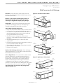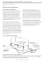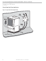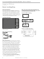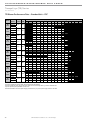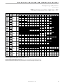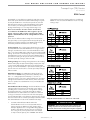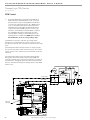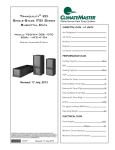
1
Tranquility® High Efficiency (TR) Series Table of Contents Models TRH/V 006 - 060 60Hz - HFC-410A INSTALLATION, OPERATION & MAINTENANCE 97B0075N08 Revised: 22 January, 2015 Model Nomenclature - General Overview 3 General Information 4 Unit Physical Data 6 Horizontal Installation 7 Field Conversion of Air Discharge 9 Horizontal Installation 10 Vertical Installation 11 Piping Installation 13 Water-Loop Heat Pump Applications 14 Ground-Loop Heat Pump Applications 15 Ground-Water Heat Pump Applications 17 Water Quality Standards 19 Electrical - Line Voltage 20 Electrical Data - Standard Unit - PSC Blower 21 Electrical Data - High Static PSC Blower 22 Electrical Data - Internal Secondary Pump - PSC Blower 23 Electrical Data - High Static PSC Blower with Internal Secondary Pump 24 25 Electrical Data with Climadry® - PSC Blower 26 Electrical Data - Climadry® & High Static PSC Blower Electrical Data - ECM Blower 27 Electrical Data - ECM Blower with Internal Secondary Pump28 Electrical Data - ECM Blower with Climadry®29 Electrical - Power Wiring 30 Electrical - Power & Low Voltage Wiring 31 Electrical - Low Voltage Wiring 32 Electrical - Thermostat Wiring 33 TR Blower Performance Data - Standard Unit - PSC 34 TR Blower Performance Data - High Static - PSC 35 Blower Performance Data with PSC and ClimaDry®36 Blower Performance Data - with High Static PSC and ClimaDry®37 Blower Performance Data (ECM Motor) 38 ECM Control 39 Typical Wiring Diagram - Units with CXM Controller and ECM Blower (Single Phase) 41 Typical Wiring Diagram - Units with CXM Board and PSC Fan Motor (Single Phase) 42 Typical Wiring Diagram - Units with DXM Board and PSC Fan Motor (Three Phase) 43 Typical Wiring Diagram - Single Phase with ClimaDry®44 CXM Controls 45 DXM Controls 46 Safety Features - CXM and DXM Controls 48 50 ClimaDry® Modulating Reheat Option Unit Starting and Operating Conditions 53 Piping System Cleaning and Flushing 54 Flushing/Purging Units with ClimaDry®55 Unit and System Checkout 56 Unit Start-Up Procedure 57 Unit Operating Conditions 59 Preventive Maintenance 63 Functional Troubleshooting 65 Performance Troubleshooting 66 Start-Up Log Sheet 67 Functional Troubleshooting 68 Warranty (U.S. & Canada) 69 Warranty (International) 70 Revision History 72 CLIMATEMASTER WATER-SOURCE HEAT PUMPS Tr a n q u i l i t y ® ( T R ) S e r i e s R e v. : 0 1 / 2 2 / 1 5 This Page Intentionally Left Blank 2 C l i m a t e M a s t e r Wa t e r - S o u r c e H e a t P u m p s THE SMART SOLUTION FOR ENERGY EFFICIENCY Tr a n q u i l i t y ® ( T R ) S e r i e s R e v. : 0 1 / 2 2 / 1 5 Model Nomenclature - General Overview 1 MODEL TYPE 2 TR 3 H 4 5 6 7 036 A 8 G 9 C 10 11 3 0 12 C 13 14 L 15 B S TR = TRANQUILITY® HIGH EFFICIENCY 410A SUPPLY AIR OPTIONS CONFIGURATION H = HORIZONTAL V = VERTICAL S = STANDARD Option T B S *V *Y *Z *K *P *W UNIT SIZE 006 - E,G 009 - E,G 012 - E,G 015 - E,G 018 - E,G 024 - E,G,H,F 030 - E,G,H,F 036 - E,G,H,F 042 - G,H,F,N 048 - G,H,F,N 060 - G,H,F,N AVAILABLE VOLTAGES Supply Configuration Motor Top TCV PSC Back TCH PSC Straight TCH PSC Top TCV PSC Hi Static TCH PSC Hi Static Back TCH PSC Hi Static Straight Top TCV ECM TCH ECM Back ECM TCH Straight * N/A for sizes 006, 009, 012 RETURN AIR OPTIONS L = LEFT RETURN R = RIGHT RETURN V = LEFT RETURN, STAINLESS STEEL DRAIN PAN W = RIGHT RETURN, STAINLESS STEEL DRAIN PAN REVISION LEVEL A = CURRENT REVISION HEAT EXCHANGER OPTIONS Non Coated Air Coil Tin-plated Air Coil Copper Cupro-nickel Copper Cupro-nickel Standard C N A J Motorized Valve T S U W ® E ClimaDry P D F VOLTAGE G = 208-230/60/1 E = 265/60/1 H = 208-230/60/3 F = 460/60/3 N = 575/60/3 WATER CIRCUIT OPTIONS 0 = None 2 = HWG (Coil Only) 5 = Internal Secondary Pump 6 = HWG (Coil Only) w/Auto Flow Regulator 2.5 GPM/Ton 7 = HWG (Coil Only) w/Auto Flow Regulator 3.0 GPM/Ton 8 = Auto Flow Regulator 2.5 GPM/Ton 9 = Auto Flow Regulator 3.0 GPM/Ton CONTROLS C = CXM D = DXM L = CXM w/LON M = DXM w/LON N = CXM w/MPC P = DXM w/MPC CABINET INSULATION 1 = EXTENDED RANGE 2 = EXTENDED RANGE w/ULTRA QUIET 3 = STANDARD RANGE 4 = STANDARD RANGE w/ULTRA QUIET NOTE: Some options/configurations not available on all series. Please consult Engineering Guides for model-specific options. ClimaDry® II Option Notes: 1. Unit must have DXM control option. 460 volt unit units require a four wire power supply with neutral. 2. ClimaDry® II may not be combined with motorized water valve, internal secondary circulating pump, or automatic flow regulator options. 3. Unit minimum entering air temperature while in the dehumidification, cooling, or continuous fan modes is 65ºF DB/55ºF WB. Operation below this minimum may result in nuisance faults. 4. A thermostat with dehumidification mode or thermostat and separate humidistat/dehumidistat is required for activation and control of ClimaDry® II. 5. Downflow units and 575 volt units are not eligible for ClimaDry® II. c l i m a t e m a s t e r. c o m 3 CLIMATEMASTER WATER-SOURCE HEAT PUMPS Storage Pre-Installation Tr a n q u i l i t y ® ( T R ) S e r i e s R e v. : 0 1 / 2 2 / 1 5 General Information Safety Warnings, cautions, and notices appear throughout this manual. Read these items carefully before attempting any installation, service, or troubleshooting of the equipment. DANGER: Indicates an immediate hazardous situation, which if not avoided will result in death or serious injury. DANGER labels on unit access panels must be observed. WARNING: Indicates a potentially hazardous situation, which if not avoided could result in death or serious injury. CAUTION: Indicates a potentially hazardous situation or an unsafe practice, which if not avoided could result in minor or moderate injury or product or property damage. NOTICE: Notification of installation, operation, or maintenance information, which is important, but which is not hazard-related. � WARNING! � WARNING! The EarthPure® Application and Service Manual should be read and understood before attempting to service refrigerant circuits with HFC-410A. � WARNING! � WARNING! To avoid the release of refrigerant into the atmosphere, the refrigerant circuit of this unit must be serviced only by technicians who meet local, state, and federal proficiency requirements. � CAUTION! � CAUTION! To avoid equipment damage, DO NOT use these units as a source of heating or cooling during the construction process. The mechanical components and filters will quickly become clogged with construction dirt and debris, which may cause system damage. � WARNING! � WARNING! The installation of water-source heat pumps and all associated components, parts, and accessories which make up the installation shall be in accordance with the regulations of ALL authorities having jurisdiction and MUST conform to all applicable codes. It is the responsibility of the installing contractor to determine and comply with ALL applicable codes and regulations. 4 � WARNING! � WARNING! All refrigerant discharged from this unit must be recovered WITHOUT EXCEPTION. Technicians must follow industry accepted guidelines and all local, state, and federal statutes for the recovery and disposal of refrigerants. If a compressor is removed from this unit, refrigerant circuit oil will remain in the compressor. To avoid leakage of compressor oil, refrigerant lines of the compressor must be sealed after it is removed. Inspection - Upon receipt of the equipment, carefully check the shipment against the bill of lading. Make sure all units have been received. Inspect the packaging of each unit, and inspect each unit for damage. Ensure that the carrier makes proper notation of any shortages or damage on all copies of the freight bill and completes a common carrier inspection report. Concealed damage not discovered during unloading must be reported to the carrier within 15 days of receipt of shipment. If not filed within 15 days, the freight company can deny the claim without recourse. Note: It is the responsibility of the purchaser to file all necessary claims with the carrier. Notify your equipment supplier of all damage within fifteen (15) days of shipment. Storage - Equipment should be stored in its original packaging in a clean, dry area. Store units in an upright position at all times. Stack units a maximum of 3 units high. Unit Protection - Cover units on the job site with either the original packaging or an equivalent protective covering. Cap the open ends of pipes stored on the job site. In areas where painting, plastering, and/or spraying has not been completed, all due precautions must be taken to avoid physical damage to the units and contamination by foreign material. Physical damage and contamination may prevent proper start-up and may result in costly equipment clean-up. C l i m a t e M a s t e r Wa t e r - S o u r c e H e a t P u m p s THE SMART SOLUTION FOR ENERGY EFFICIENCY Tr a n q u i l i t y ® ( T R ) S e r i e s R e v. : 0 1 / 2 2 / 1 5 General Information Examine all pipes, fittings, and valves before installing any of the system components. Remove any dirt or debris found in or on these components. Pre-Installation - Installation, Operation, and Maintenance instructions are provided with each unit. Horizontal equipment is designed for installation above false ceiling or in a ceiling plenum. Other unit configurations are typically installed in a mechanical room. The installation site chosen should include adequate service clearance around the unit. Before unit start-up, read all manuals and become familiar with the unit and its operation. Thoroughly check the system before operation. Prepare units for installation as follows: 1. Compare the electrical data on the unit nameplate with ordering and shipping information to verify that the correct unit has been shipped. 2. Keep the cabinet covered with the original packaging until installation is complete and all plastering, painting, etc. is finished. 3. Verify refrigerant tubing is free of kinks or dents and that it does not touch other unit components. 4. Inspect all electrical connections. Connections must be clean and tight at the terminals. 5. Remove any blower support packaging (water-to-air units only). 6. Loosen compressor bolts on units equipped with compressor spring vibration isolation until the compressor rides freely on the springs. Remove shipping restraints. (No action is required for compressors with rubber grommets.) 7. Some airflow patterns are field convertible (horizontal units only). Locate the airflow conversion section of this IOM. 8. Locate and verify any hot water generator (HWG), hanger, or other accessory kit located in the compressor section or blower section. � CAUTION! � CAUTION! All three phase scroll compressors must have direction of rotation verified at start-up. Verification is achieved by checking compressor Amp draw. Amp draw will be substantially lower compared to nameplate values. Additionally, reverse rotation results in an elevated sound level compared to correct rotation. Reverse rotation will result in compressor internal overload trip within several minutes. Verify compressor type before proceeding. � CAUTION! � CAUTION! DO NOT store or install units in corrosive environments or in locations subject to temperature or humidity extremes (e.g., attics, garages, rooftops, etc.). Corrosive conditions and high temperature or humidity can significantly reduce performance, reliability, and service life. Always move and store units in an upright position. Tilting units on their sides may cause equipment damage. � CAUTION! � CAUTION! CUT HAZARD - Failure to follow this caution may result in personal injury. Sheet metal parts may have sharp edges or burrs. Use care and wear appropriate protective clothing, safety glasses and gloves when handling parts and servicing heat pumps. NOTICE! Failure to remove shipping brackets from spring-mounted compressors will cause excessive noise, and could cause component failure due to added vibration. c l i m a t e m a s t e r. c o m 5 CLIMATEMASTER WATER-SOURCE HEAT PUMPS Tr a n q u i l i t y ® ( T R ) S e r i e s R e v. : 0 1 / 2 2 / 1 5 Unit Physical Data Tranquility® (TR) Series (60 Hz) TR Series 006 009 012 Compressor (1 each) Factory Charge HFC-410A - (oz.) 015 018 024 030 036 Rotary 042 048 060 Scroll 17 18.5 23 35 43 40 48 50 70 74 82 N/A N/A N/A 9x7 9x7 9x7 9x7 9x8 9x8 10x10 11x10 PSC/3 PSC/3 PSC/3 PSC/3 PSC/3 PSC/3 PSC/3 PSC/3 PSC/3 PSC/3 PSC/3 5x5 5x5 6x5 8x7 8x7 9x7 9x7 9x8 9x8 10x10 11x10 1/2” 1/2” 1/2” 1/2” 1/2” 3/4” 3/4” 3/4” 3/4” 1” 1” ECM Fan Motor & Blower Blower Wheel Size (Dia x w) PSC Fan Motor & Blower Fan Motor Type/Speeds Blower Wheel Size (Dia x W) Water Connection Size Source FPT Optional HWG FPT Coax Volume (gallons) 1/2” 0.123 0.143 0.167 0.286 0.45 0.286 0.323 0.323 0.89 0.738 0.939 Air Coil Dimensions (H x W) 10x15 10x15 10x15 20x17.25 20x17.25 20x17.25 20x17.25 24x21.75 24x21.76 28x25 28x25 Filter Standard - 1” Throwaway 10x18 10x18 10x18 20x20 20x20 20x20 20x20 24x24 24x24 28x28 28x28 Weight - Operating (lbs.) 110 112 121 163 168 184 192 213 228 283 298 Weight - Packaged (lbs.) 115 117 126 168 173 189 197 219 234 290 305 Air Coil Dimensions (H x W) 10x15 10x15 10x15 16x22 16x22 16x22 16x22 20x25 20x25 20x35 20x35 Filter Standard - 1” Throwaway 10x18 10x18 10x18 16x25 16x25 18x25 18x25 20x28 or 2-20x14 20x28 or 2-20x14 1-20x24, 1-20x14 1-20x24, 1-20x14 Weight - Operating (lbs.) 110 112 121 163 168 184 192 213 228 283 298 Weight - Packaged (lbs.) 115 117 126 168 173 189 197 219 234 290 305 Vertical Horizontal Notes: All units have TXV expansion device and 1/2” & 3/4” electrical knockouts. 575 volt fan motors are two speed. FPT=Female Pipe Thread Condensate Drain Connection is 3/4” FPT. For ClimaDry® option add 66lbs (30kg). Unit Maximum Water Working Pressure Options Max Pressure PSIG [kPa] Base Unit 500 [3447] Internal Secondary Pump (ISP) 145 [999] Internal Motorized Water Valve (MWV) 300 [2,068] Internal Auto Flow Valve 300 [2,068] ClimaDry® 145 [999] Use the lowest maximum pressure rating when multiple options are combined. 6 C l i m a t e M a s t e r Wa t e r - S o u r c e H e a t P u m p s THE SMART SOLUTION FOR ENERGY EFFICIENCY Tr a n q u i l i t y ® ( T R ) S e r i e s R e v. : 0 1 / 2 2 / 1 5 Horizontal Installation Horizontal Unit Location Units are not designed for outdoor installation. Locate the unit in an INDOOR area that allows enough space for service personnel to perform typical maintenance or repairs without removing unit from the ceiling. Horizontal units are typically installed above a false ceiling or in a ceiling plenum. Never install units in areas subject to freezing or where humidity levels could cause cabinet condensation (such as unconditioned spaces subject to 100% outside air). Consideration should be given to access for easy removal of the filter and access panels. Provide sufficient room to make water, electrical, and duct connection(s). If the unit is located in a confined space, such as a closet, provisions must be made for return air to freely enter the space by means of a louvered door, etc. Any access panel screws that would be difficult to remove after the unit is installed should be removed prior to setting the unit. Refer to Figure 3 for an illustration of a typical installation. Refer to unit submittal data or engineering design guide for dimensional data. In limited side access installations, pre-removal of the control box side mounting screws will allow control box removal for future servicing. Mounting Horizontal Units Horizontal units have hanger kits pre-installed from the factory as shown in Figure 1. Figure 3 shows a typical horizontal unit installation. Horizontal heat pumps are typically suspended above a ceiling or within a soffit using field supplied, threaded rods sized to support the weight of the unit. Use four (4) field supplied threaded rods and factory provided vibration isolators to suspend the unit. Hang the unit clear of the floor slab above and support the unit by the mounting bracket assemblies only. DO NOT attach the unit flush with the floor slab above. Pitch the unit toward the drain as shown in Figure 2 to improve the condensate drainage. On small units (less than 2.5 tons/8.8kW) ensure that unit pitch does not cause condensate leaks inside the cabinet. Figure 1: Hanger Bracket 3/8" [10mm] Threaded Rod (by others) Vibration Isolator (factory supplied) Conform to the following guidelines when selecting unit location: Washer 1. Provide a hinged access door in concealed-spline (by others) or plaster ceilings. Provide removable ceiling Double Hex Nuts tiles in T-bar or lay-in ceilings. Refer to horizontal (by others) unit dimensions for specific series and model in unit submittal data. Size the access opening to accommodate the service technician during the removal or replacement of the compressor and the removal or installation of the unit itself. 2. Provide access to hanger brackets, water valves and fittings. Provide screwdriver clearance to access Figure 2: Horizontal Unit Pitch panels, discharge collars and all electrical connections. Varilla Roscada de 3/8" 3. DO NOT obstruct the space beneath the unit with (fabricada por terceros) piping, electrical cables and other items that prohibit future removal of components or the unit itself. Aislador de Vibraciones (para codificación por color y 4. Use a manual portable jack/lift to lift and supportnotas the de instalación, consulte weight of the unit during installation and servicing. las instrucciones de instalación del soport e colgador) The installation of water source heat pump units and all Arandela associated components, parts and accessories which (fabricada por terceros) make up the installation shall be in accordance with the regulations of ALL authorities having jurisdiction and MUST conform to all applicable codes. It is the responsibility of the installing contractor to determine and comply with ALL applicable codes and regulations. 1/4” (6.4mm) pitch toward drain for drainage Drain Connection Tuercas Hexagonales Dobles (por terceros) Instale los Tornillos como se Indica en el Diagrama La longitud de este tornillo c l i m a t e mdebe a s t e rser . c ode m solamente 1/2” para evitar daños 7 CLIMATEMASTER WATER-SOURCE HEAT PUMPS Tr a n q u i l i t y ® ( T R ) S e r i e s R e v. : 0 1 / 2 2 / 1 5 Horizontal Installation HORIZONTAL INSTALLATION Figure Typical Horizontal Unit Installation Figure3:3: Typical Horizontal Unit Installation 3/8" [10mm] threaded rods (by others) Return Air Thermostat Wiring Power Wiring Optional Low Pressure Drop Water Control Valve (can be internally mounted on some models) Stainless steel braid hose with integral "J" swivel Supply Air Optional Balancing Valve Unit Power Insulated supply duct with at least one 90 deg elbow to reduce air noise Flexible Duct Connector Building Loop Unit Power Disconnect (by others) Water Out Water In Ball Valve with optional integral P/T plug Unit Hanger Air Coil - To obtain maximum performance, the air coil should be cleaned before start-up. A 10% solution of dishwasher detergent and water is recommended for both sides of the coil. A thorough water rinse should follow. UV based anti-bacterial systems may damage e-coated air coils. Notice! Installation Note - Ducted Return: Many horizontal WSHPs are installed in a return air ceiling plenum application (above ceiling). Vertical WSHPs are commonly installed in a mechanical room with free return (e.g. louvered door). Therefore, filter rails are the industry standard and are included on ClimateMaster commercial heat pumps for the purposes of holding the filter only. For ducted return applications, the filter rail must be removed and replaced with a duct flange or filter frame. Canvas or flexible connectors should also be used to minimize vibration between the unit and ductwork. Varillas Roscadas de 3/8" (fabricadas por terceros) Retorno de aire Cableado del termostato Alimentación de energía de la unidad Aire de alimentación Manguera trenzada de acero inoxidable con accesorio giratorio en “J” Válvula compensadora opcional Válvula invertida opcional para control de baja presión de agua (puede montarse en forma interna) Colgador de la unidad Conducto de alimentación aislado con un codo (mínimo) de 90 grados para reducir el ruido del aire Disyuntor de energía de la unidad (fabricado por terceros) Entrada de agua Salida de agua Cableado de alimentación de energía 8 Circuito de edificación C l i m a t e M a s t e r Wa t e r - S o u r c e H e a t P u m p s Válvula a bola con tapón P/T integrado opcional THE SMART SOLUTION FOR ENERGY EFFICIENCY Tr a n q u i l i t y ® ( T R ) S e r i e s R e v. : 0 1 / 2 2 / 1 5 Field Conversion of Air Discharge Overview - Horizontal units can be field converted between side (straight) and back (end) discharge using the instructions below. Figure 4: Left Return Side to Back Remove Screws Water Connection End Note: It is not possible to field convert return air between left or right return models due to the necessity of refrigeration copper piping changes. Return Air Preparation - It is best to field convert the unit on the ground before hanging. If the unit is already hung it should be taken down for the field conversion. Side to Back Discharge Conversion 1. Place unit in well lit area. Remove the screws as shown in Figure 4 to free top panel and discharge panel. 2. Lift out the access panel and set aside. Lift and rotate the discharge panel to the other position as shown, being careful with the blower wiring. 3. Check blower wire routing and connections for tension or contact with sheet metal edges. Re-route if necessary. 4. Check refrigerant tubing for contact with other components. 5. Reinstall top panel and screws noting that the location for some screws will have changed. 6. Manually spin the fan wheel to ensure that the wheel is not rubbing or obstructed. 7. Replace access panels. Side Discharge Water Connection End Rotate Return Air Move to Side Replace Screws Water Connection End Return Air Back to Side Discharge Conversion - If the discharge is changed from back to side, use above instruction noting that illustrations will be reversed. Left vs. Right Return - It is not possible to field convert return air between left or right return models due to the necessity of refrigeration copper piping changes. However, the conversion process of side to back or back to side discharge for either right or left return configuration is the same. In some cases, it may be possible to rotate the entire unit 180 degrees if the return air connection needs to be on the opposite side. Note that rotating the unit will move the piping to the other end of the unit. Drain Discharge Air Back Discharge Figure 5: Right Return Side to Back Water Connection End Return Air Supply Duct Side Discharge Water Connection End Return Air Drain Discharge Air c l i m a t e m a s t e r. c o m Back Discharge 9 CLIMATEMASTER WATER-SOURCE HEAT PUMPS Tr a n q u i l i t y ® ( T R ) S e r i e s Condensate Piping R e v. : 0 1 / 2 2 / 1 5 Duct System Installation Horizontal Installation Condensate Piping - Horizontal Units - A condensate drain line must be installed and pitched away for the unit to allow for proper drainage. This connection must meet all local plumbing/building codes. Pitch the unit toward the drain as shown in Figure 2 to improve the condensate drainage. On small units (less than 2.5 tons/8.8 kW), ensure that unit pitch does not cause condensate leaks inside the cabinet. Install condensate trap at each unit with the top of the trap positioned below the unit condensate drain connection as shown in Figure 6. Design the depth of the trap (water-seal) based upon the amount of ESP capability of the blower (where 2 inches [51mm] of ESP capability requires 2 inches [51mm] of trap depth). As a general rule, 1-1/2 inch [38mm] trap depth is the minimum. Each unit must be installed with its own individual trap and connection to the condensate line (main) or riser. Provide a means to flush or blow out the condensate line. DO NOT install units with a common trap and/or vent. Always vent the condensate line when dirt or air can collect in the line or a long horizontal drain line is required. Also vent when large units are working against higher external static pressure than other units connected to the same condensate main since this may cause poor drainage for all units on the line. WHEN A VENT IS INSTALLED IN THE DRAIN LINE, IT MUST BE LOCATED AFTER THE TRAP IN THE DIRECTION OF THE CONDENSATE FLOW. Figure 6: Horizontal Condensate Connection 2” 1/8” Per Foot 1.5” 1.5” * Some units include a painted drain connection. Using a threaded pipe or similar device to clear any excess paint accumulated inside this fitting may ease final drain line installation. � CAUTION! � CAUTION! Ensure condensate line is pitched toward drain 1/8 inch per ft [11mm per m] of run. Duct System Installation - Proper duct sizing and design is critical to the performance of the unit. The duct system should be designed to allow adequate and even airflow through the unit during operation. Air flow through the unit MUST be at or above the minimum stated airflow for the unit to avoid equipment damage. Duct systems should be designed for quiet operation. Refer to Figure 3 for horizontal duct system details or Figure 8 for vertical duct system details. A flexible connector is recommended for both discharge and return air duct connections on metal duct systems to eliminate the transfer of vibration to the duct system. To maximize sound attenuation of the unit blower, the supply and return plenums should include internal fiberglass duct liner or be constructed from ductboard for the first few feet. Application of the unit to uninsulated ductwork in an unconditioned space is not recommended, as the unit’s performance may be adversely affected. At least one 90° elbow should be included in the supply duct to reduce air noise. If air noise or excessive air flow is a problem, the blower speed can be changed. For airflow charts, consult submittal data for the series and model of the specific unit. If the unit is connected to existing ductwork, a previous check should have been made to ensure that the ductwork has the capacity to handle the airflow required for the unit. If ducting is too small, as in the replacement of a heating only system, larger ductwork should be installed. All existing ductwork should be checked for leaks and repaired as necessary. 10 C l i m a t e M a s t e r Wa t e r - S o u r c e H e a t P u m p s THE SMART SOLUTION FOR ENERGY EFFICIENCY (TR) Series Tr a n q u iUnit l i t y ®Location Vertical R e v. : 0 1 / 2 2 / 1 5 Vertical Installation Vertical Unit Location - Units are not designed for outdoor installation. Locate the unit in an INDOOR area that allows enough space for service personnel to perform typical maintenance or repairs without removing unit from the mechanical room/closet. Vertical units are typically installed in a mechanical room or closet. Never install units in areas subject to freezing or where humidity levels could cause cabinet condensation (such as unconditioned spaces subject to 100% outside air). Consideration should be given to access for easy removal of the filter and access panels. Provide sufficient room to make water, electrical, and duct connection(s). If the unit is located in a confined space, such as a closet, provisions must be made for return air to freely enter the space by means of a louvered door, etc. Any access panel screws that would be difficult to remove after the unit is installed should be removed prior to setting the unit. Refer to Figures 7 and 8 for typical installation illustrations. Refer to unit submittal data or engineering design guide for dimensional data. 1. Install the unit on a piece of rubber, neoprene or other mounting pad material for sound isolation. The pad should be at least 3/8” [10mm] to 1/2” [13mm] in thickness. Extend the pad beyond all four edges of the unit. 2. Provide adequate clearance for filter replacement and drain pan cleaning. Do not block filter access with piping, conduit or other materials. Refer to unit submittal data or engineering design guide for dimensional data. 3. Provide access for fan and fan motor maintenance and for servicing the compressor and coils without removing the unit. 4. Provide an unobstructed path to the unit within the closet or mechanical room. Space should be sufficient to allow removal of the unit, if necessary. 5. Provide access to water valves and fittings and screwdriver access to the unit side panels, discharge collar and all electrical connections. Figure 7: Vertical Unit Mounting Air Pad or extruded polystyrene insulation board Figure 8: Typical Vertical Unit Installation Using Ducted Return Air Internally insulate supply duct for the first 4’ (1.2m) each way to reduce noise Use turning vanes in supply transition Flexible canvas duct connector to reduce noise and vibration Remove supply duct flanges from inside blower compartment and install on supply air opening of unit. Do not use a supply air plenum/duct smaller than the size of the supply duct flanges. Cojín del aire o sacado Bloque o ladrillo concreto Internally insulate return bloque transition o del ladrillo duct otosacado reduce noise Rounded return transition Rev.: 2/13 Notice! Installation Note - Ducted Return: Many horizontal WSHPs are installed in a return air ceiling plenum application (above ceiling). Vertical WSHPs are commonly installed in a mechanical room with free return Internally insulate supply (e.g. louvered door). Therefore, filter railsduct are the for first 1.2industry m each way to reduce noise standard and are included on ClimateMaster commercial vanes in heat pumps for the purposes of holding Use theturning filter only. supply transition For ducted return applications, the filter rail must be removed and replaced with a duct flange or filter frame. Flexible canvas duct Canvas or flexible connectors should also be used to connector to reduce and vibration minimize vibration between the unit andnoise ductwork. c l i m a t e m a s t e r. c o m Remove supply duct flanges from inside blower compartment and install on supply air opening of 11 CLIMATEMASTER WATER-SOURCE HEAT PUMPS Tr a n q u i l i t y ® ( T R ) S e r i e s R e v. : 0 1 / 2 2 / 1 5 Vertical Installation Sound Attenuation for Vertical Units - Sound attenuation is achieved by enclosing the unit within a small mechanical room or a closet. Additional measures for sound control include the following: 1. Mount the unit so that the return air inlet is 90° to the return air grille. Refer to Figure 9. Install a sound baffle as illustrated to reduce line-of sight sound transmitted through return air grilles. 2. Mount the unit on a rubber or neoprene isolation pad to minimize vibration transmission to the building structure. Figure 9: Vertical Sound Attenuation Condensate Piping for Vertical Units - A condensate line must be installed and pitched away from the unit to allow for proper drainage. This connection must meet all local plumbing/building codes. Vertical units utilize a condensate hose inside the cabinet as a trapping loop; therefore an external trap is not necessary. Figure 10a shows typical condensate connections. Figure 10b illustrates the internal trap for a typical vertical heat pump. Each unit must be installed with its own individual vent (where necessary) and a means to flush or blow out the condensate drain line. Do not install units with a common trap and/or vent. Figure 10a: Vertical Condensate Drain *3/4" FPT Vent 3/4" PVC 1/8" per foot slope to drain Return Air Inlet Water Connections Alternate Condensate Location * Some units include a painted drain connection. Using a threaded pipe or similar device to clear any excess paint accumulated inside this fitting may ease final drain line installation. Figure 10b: Vertical Internal Condensate Trap Notice! Units with clear plastic drain lines should have regular maintenance (as required) to avoid buildup of debris, especially in new construction. 12 C l i m a t e M a s t e r Wa t e r - S o u r c e H e a t P u m p s THE SMART SOLUTION FOR ENERGY EFFICIENCY Tr a n q u i l i t y ® ( T R ) S e r i e s R e v. : 0 1 / 2 2 / 1 5 Piping Installation Installation of Supply and Return Piping Follow these piping guidelines. 1. Install a drain valve at the base of each supply and return riser to facilitate system flushing. 2. Install shut-off / balancing valves and unions at each unit to permit unit removal for servicing. 3. Place strainers at the inlet of each system circulating pump. 4. Select the proper hose length to allow slack between connection points. Hoses may vary in length by +2% to -4% under pressure. 5. Refer to Table 1. Do not exceed the minimum bend radius for the hose selected. Exceeding the minimum bend radius may cause the hose to collapse, which reduces water flow rate. Install an angle adapter to avoid sharp bends in the hose when the radius falls below the required minimum. Insulation is not required on loop water piping except where the piping runs through unheated areas, outside the building or when the loop water temperature is below the minimum expected dew point of the pipe ambient conditions. Insulation is required if loop water temperature drops below the dew point (insulation is required for ground loop applications in most climates). Pipe joint compound is not necessary when Teflon® thread tape is pre-applied to hose assemblies or when flared-end connections are used. If pipe joint compound is preferred, use compound only in small amounts on the external pipe threads of the fitting adapters. Prevent sealant from reaching the flared surfaces of the joint. Note: When antifreeze is used in the loop, ensure that it is compatible with the Teflon® tape or pipe joint compound that is applied. Maximum allowable torque for brass fittings is 30 ft-lbs [41 N-m]. If a torque wrench is not available, tighten finger-tight plus one quarter turn. Tighten steel fittings as necessary. Optional pressure-rated hose assemblies designed specifically for use with ClimateMaster units are available. Similar hoses can be obtained from alternate suppliers. Supply and return hoses are fitted with swivel-joint fittings at one end to prevent kinking during installation. Refer to Figure 11 for an illustration of a typical supply/ return hose kit. Adapters secure hose assemblies to the unit and risers. Install hose assemblies properly and check regularly to avoid system failure and reduced service life. Installer Caution: After making water connections on units equipped with ClimaDry®, ensure the three union nuts on the internal three-way water valve are tight. ClimaDry®-equipped units have a manual air bleed valve at the top of the reheat coil. This valve must be used to bleed the air from the reheat coil after filling the system, for the ClimaDry® to operate properly. A backup wrench is required when tightening water connections on TC Series units to prevent water line damage. � WARNING! � WARNING! Polyolester Oil, commonly known as POE oil, is a synthetic oil used in many refrigeration systems including those with HFC-410A refrigerant. POE oil, if it ever comes in contact with PVC or CPVC piping, may cause failure of the PVC/CPVC. PVC/CPVC piping should never be used as supply or return water piping with water source heat pump products containing HFC-410A as system failures and property damage may result. � CAUTION! � CAUTION! Corrosive system water requires corrosion resistant fittings and hoses, and may require water treatment. � CAUTION! � CAUTION! Do not bend or kink supply lines or hoses. � CAUTION! � CAUTION! Piping must comply with all applicable codes. Table 1: Metal Hose Minimum Bend Radii Hose Diameter Minimum Bend Radii 1/2" [12.7mm] 3/4" [19.1mm] 1" [25.4mm] 1-1/4" [31.8mm] 2-1/2" [6.4cm] 4" [10.2cm] 5-1/2" [14cm] 6-3/4" [17.1cm] NOTICE! Do not allow hoses to rest against structural building components. Compressor vibration may be transmitted through the hoses to the structure, causing unnecessary noise complaints. Figure 11: Supply/Return Hose Kit Rib Crimped MPT c l i m a t e m a s t e r. c o m Length (0.6m Length Standard) Swivel Brass Fitting Brass Fitting MPT 13 CLIMATEMASTER WATER-SOURCE HEAT PUMPS Tr a n q u i l i t y ® ( T R ) S e r i e s R e v. : 0 1 / 2 2 / 1 5 Water-Loop Heat Pump Applications Commercial Water Loop Applications Commercial systems typically include a number of units connected to a common piping system. Any unit plumbing maintenance work can introduce air into the piping system; therefore air elimination equipment is a major portion of the mechanical room plumbing. Consideration should be given to insulating the piping surfaces to avoid condensation. ClimateMaster recommends unit insulation any time the water temperature is expected to be below 60ºF (15.6ºC). Metal to plastic threaded joints should never be used due to their tendency to leak over time. Teflon® tape thread sealant is recommended to minimize internal fouling of the heat exchanger. Do not over tighten connections and route piping so as not to interfere with service or maintenance access. Hose kits are available from ClimateMaster in different configurations as shown in Figure 12 for connection between the unit and the piping system. Depending upon selection, hose kits may include shut off valves, P/T plugs for performance measurement, high pressure stainless steel braided hose, “Y” type strainer with blow down valve, and/or “J” type swivel connection. Balancing valves and an external low pressure drop solenoid valve for use in variable speed pumping systems may also be included in the hose kit. The piping system should be flushed to remove dirt, piping chips, and other foreign material prior to operation (see “Piping System Cleaning and Flushing Procedures” in this manual). The flow rate is usually set between 2.25 and 3.5 gpm per ton [2.9 and 4.5 l/m per kW] of cooling capacity. ClimateMaster recommends 3 gpm per ton [3.9 l/m per kW] for most applications of water loop heat pumps. To ensure proper maintenance and servicing, P/T ports are imperative for temperature and flow verification, as well as performance checks. Water loop heat pump (cooling tower/boiler) systems typically utilize a common loop, maintained between 60 - 90°F [16 - 32°C]. The use of a closed circuit evaporative cooling tower with a secondary heat exchanger between the tower and the water loop is recommended. If an open type cooling tower is used continuously, chemical treatment and filtering will be necessary. Figure 12: Typical Water-Loop Application 3/8" [10mm] threaded rods (by others) Low Water Temperature Cutout Setting - CXM Control When antifreeze is selected, the LT1 jumper (JW3) should be clipped to select the low temperature (antifreeze 10.0°F [-12.2°C]) setpoint and avoid nuisance faults (see “Low Water Temperature Cutout Selection” in this manual). Note: Low water temperature operation requires extended range equipment. 14 C l i m a t e M a s t e r Wa t e r - S o u r c e H e a t P u m p s THE SMART SOLUTION FOR ENERGY EFFICIENCY Tr a n q u i l i t y ® ( T R ) S e r i e s R e v. : 0 1 / 2 2 / 1 5 Ground-Loop Heat Pump Applications � CAUTION! � CAUTION! The following instructions represent industry accepted installation practices for closed loop earth coupled heat pump systems. Instructions are provided to assist the contractor in installing trouble free ground loops. These instructions are recommendations only. State/provincial and local codes MUST be followed and installation MUST conform to ALL applicable codes. It is the responsibility of the installing contractor to determine and comply with ALL applicable codes and regulations. � CAUTION! � CAUTION! Ground loop applications require extended range equipment and optional refrigerant/water circuit insulation. Pre-Installation Prior to installation, locate and mark all existing underground utilities, piping, etc. Install loops for new construction before sidewalks, patios, driveways, and other construction has begun. During construction, accurately mark all ground loop piping on the plot plan as an aid in avoiding potential future damage to the installation. Piping Installation The typical closed loop ground source system is shown in Figure 13. All earth loop piping materials should be limited to polyethylene fusion only for in-ground sections of the loop. Galvanized or steel fittings should not be used at any time due to their tendency to corrode. All plastic to metal threaded fittings should be avoided due to their potential to leak in earth coupled applications. A flanged fitting should be substituted. P/T plugs should be used so that flow can be measured using the pressure drop of the unit heat exchanger. Earth loop temperatures can range between 25 and 110°F [-4 to 43°C]. Flow rates between 2.25 and 3 gpm [2.41 to 3.23 l/m per kW] of cooling capacity is recommended in these applications. Test individual horizontal loop circuits before backfilling. Test vertical U-bends and pond loop assemblies prior to installation. Pressures of at least 100 psi [689 kPa] should be used when testing. Do not exceed the pipe pressure rating. Test entire system when all loops are assembled. Flushing the Earth Loop Upon completion of system installation and testing, flush the system to remove all foreign objects and purge to remove all air. Antifreeze In areas where minimum entering loop temperatures drop below 40°F [5°C] or where piping will be routed through areas subject to freezing, antifreeze is required. Alcohols and glycols are commonly used as antifreeze; however your local sales office should be consulted to determine the antifreeze best suited to your area. Freeze protection should be maintained to 15°F [9°C] below the lowest expected entering loop temperature. For example, if 30°F [-1°C] is the minimum expected entering loop temperature, the leaving loop temperature would be 22 to 25°F [-6 to -4°C] and freeze protection should be at 15°F [-10°C]. Calculation is as follows: 30°F - 15°F = 15°F [-1°C - 9°C = -10°C]. All alcohols should be premixed and pumped from a reservoir outside of the building when possible or introduced under the water level to prevent fumes. Calculate the total volume of fluid in the piping system. Then use the percentage by volume shown in table 2 for the amount of antifreeze needed. Antifreeze concentration should be checked from a well mixed sample using a hydrometer to measure specific gravity. Low Water Temperature Cutout Setting - CXM Control When antifreeze is selected, the LT1 jumper (JW3) should be clipped to select the low temperature (antifreeze 10.0°F [-12.2°C]) setpoint and avoid nuisance faults (see “Low Water Temperature Cutout Selection” in this manual). Note: Low water temperature operation requires extended range equipment. Table 2: Antifreeze Percentages by Volume Type Minimum Temperature for Low Temperature Protection 10°F [-12.2°C] 15°F [-9.4°C] 20°F [-6.7°C] 25°F [-3.9°C] 25% 38% 29% 21% 25% 25% 16% 22% 20% 10% 15% 14% Methanol 100% USP food grade Propylene Glycol Ethanol* * Must not be denatured with any petroleum based product c l i m a t e m a s t e r. c o m 15 CLIMATEMASTER WATER-SOURCE HEAT PUMPS Tr a n q u i l i t y ® ( T R ) S e r i e s R e v. : 0 1 / 2 2 / 1 5 Ground-Loop Heat Pump Applications Figure 13: Typical Ground-Loop Application To Thermostat High and Low Voltage Knockouts Vibration Isolation Pad 16 C l i m a t e M a s t e r Wa t e r - S o u r c e H e a t P u m p s THE SMART SOLUTION FOR ENERGY EFFICIENCY Tr a n q u i l i t y ® ( T R ) S e r i e s R e v. : 0 1 / 2 2 / 1 5 Ground-Water Heat Pump Applications Open Loop - Ground Water Systems - Typical open loop piping is shown in Figure 14. Shut off valves should be included for ease of servicing. Boiler drains or other valves should be “tee’d” into the lines to allow acid flushing of the heat exchanger. Shut off valves should be positioned to allow flow through the coax via the boiler drains without allowing flow into the piping system. P/T plugs should be used so that pressure drop and temperature can be measured. Supply and return water piping materials should be limited to copper, PE, or similar material. PVC or CPVC should never be used as they are incompatible with the POE oils used in HFC-410A products and piping system failure and property damage may result. � WARNING! � WARNING! Polyolester Oil, commonly known as POE oil, is a synthetic oil used in many refrigeration systems including those with HFC-410A refrigerant. POE oil, if it ever comes in contact with PVC or CPVC piping, may cause failure of the PVC/CPVC. PVC/CPVC piping should never be used as supply or return water piping with water source heat pump products containing HFC-410A as system failures and property damage may result. Water quantity should be plentiful and of good quality. Consult table 3 for water quality guidelines. The unit can be ordered with either a copper or cupro-nickel water heat exchanger. Consult Table 3 for recommendations. Copper is recommended for closed loop systems and open loop ground water systems that are not high in mineral content or corrosiveness. In conditions anticipating heavy scale formation or in brackish water, a cupro-nickel heat exchanger is recommended. In ground water situations where scaling could be heavy or where biological growth such as iron bacteria will be present, an open loop system is not recommended. Heat exchanger coils may over time lose heat exchange capabilities due to build up of mineral deposits. Heat exchangers must only be serviced by a qualified technician, as acid and special pumping equipment is required. Desuperheater coils can likewise become scaled and possibly plugged. In areas with extremely hard water, the owner should be informed that the heat exchanger may require occasional acid flushing. In some cases, the desuperheater option should not be recommended due to hard water conditions and additional maintenance required. Water Quality Standards - Table 3 should be consulted for water quality requirements. Scaling potential should be assessed using the pH/Calcium hardness method. If the pH <7.5 and the calcium hardness is less than 100 ppm, scaling potential is low. If this method yields numbers out of range of those listed, the Ryznar Stability and Langelier Saturation indecies should be calculated. Use the appropriate scaling surface temperature for the application, 150°F [66°C] for direct use (well water/open loop) and DHW (desuperheater); 90°F [32°F] for indirect use. A monitoring plan should be implemented in these probable scaling situations. Other water quality issues such as iron fouling, corrosion prevention and erosion and clogging should be referenced in Table 3. Expansion Tank and Pump - Use a closed, bladdertype expansion tank to minimize mineral formation due to air exposure. The expansion tank should be sized to provide at least one minute continuous run time of the pump using its drawdown capacity rating to prevent pump short cycling. Discharge water from the unit is not contaminated in any manner and can be disposed of in various ways, depending on local building codes (e.g. recharge well, storm sewer, drain field, adjacent stream or pond, etc.). Most local codes forbid the use of sanitary sewer for disposal. Consult your local building and zoning department to assure compliance in your area. Water Control Valve - Note the placement of the water control valve in Figure 14. Always maintain water pressure in the heat exchanger by placing the water control valve(s) on the discharge line to prevent mineral precipitation during the off-cycle. Pilot operated slow closing valves are recommended to reduce water hammer. If water hammer persists, a mini-expansion tank can be mounted on the piping to help absorb the excess hammer shock. Ensure that the total ‘VA’ draw of the valve can be supplied by the unit transformer. For instance, a slow closing valve can draw up to 35VA. This can overload smaller 40 or 50 VA transformers depending on the other controls in the circuit. A typical pilot operated solenoid valve draws approximately 15VA (see Figure 19). Note the special wiring diagrams for slow closing valves (Figures 20 & 21). c l i m a t e m a s t e r. c o m 17 CLIMATEMASTER WATER-SOURCE HEAT PUMPS Tr a n q u i l i t y ® ( T R ) S e r i e s R e v. : 0 1 / 2 2 / 1 5 Ground-Water Heat Pump Applications Flow Regulation - Flow regulation can be accomplished by two methods. One method of flow regulation involves simply adjusting the ball valve or water control valve on the discharge line. Measure the pressure drop through the unit heat exchanger, and determine flow rate from Table 9. Since the pressure is constantly varying, two pressure gauges may be needed. Adjust the valve until the desired flow of 1.5 to 2 gpm per ton [2.0 to 2.6 l/m per kW] is achieved. A second method of flow control requires a flow control device mounted on the outlet of the water control valve. The device is typically a brass fitting with an orifice of rubber or plastic material that is designed to allow a specified flow rate. On occasion, flow control devices may produce velocity noise that can be reduced by applying some back pressure from the ball valve located on the discharge line. Slightly closing the valve will spread the pressure drop over both devices, lessening the velocity noise. Note: When EWT is below 50°F [10°C], 2 gpm per ton (2.6 l/m per kW) is required. Water Coil Low Temperature Limit Setting - For all open loop systems the 30°F [-1.1°C] LT1 setting (factory setting-water) should be used to avoid freeze damage to the unit. See “Low Water Temperature Cutout Selection” in this manual for details on the low limit setting. Figure 14: Typical Open Loop/Well Application Flow Water Control Regulator Valve Pressure Tank Water Out P/T Plugs 18 Boiler Drains Optional Filter Water In Shut-Off Valve C l i m a t e M a s t e r Wa t e r - S o u r c e H e a t P u m p s THE SMART SOLUTION FOR ENERGY EFFICIENCY Tr a n q u i l i t y ® ( T R ) S e r i e s R e v. : 0 1 / 2 2 / 1 5 Water Quality Standards Table 3: Water Quality Standards Water Quality Parameter HX Material Closed Recirculating Open Loop and Recirculating Well Scaling Potential - Primary Measurement Above the given limits, scaling is likely to occur. Scaling indexes should be calculated using the limits below pH/Calcium Hardness Method All - pH < 7.5 and Ca Hardness <100ppm Index Limits for Probable Scaling Situations - (Operation outside these limits is not recommended) Scaling indexes should be calculated at 66°C for direct use and HWG applications, and at 32°C for indirect HX use. A monitoring plan should be implemented. Ryznar 6.0 - 7.5 All Stability Index If >7.5 minimize steel pipe use. -0.5 to +0.5 Langelier All If <-0.5 minimize steel pipe use. Based upon 66°C HWG and Saturation Index Direct well, 29°C Indirect Well HX Iron Fouling Iron Fe 2+ (Ferrous) (Bacterial Iron potential) All Iron Fouling All - <0.2 ppm (Ferrous) If Fe2+ (ferrous)>0.2 ppm with pH 6 - 8, O2<5 ppm check for iron bacteria. - <0.5 ppm of Oxygen Above this level deposition will occur . Corrosion Prevention 6 - 8.5 pH All Hydrogen Sulfide (H2S) All Ammonia ion as hydroxide, chloride, nitrate and sulfate compounds All Monitor/treat as needed - 6 - 8.5 Minimize steel pipe below 7 and no open tanks with pH <8 <0.5 ppm At H2S>0.2 ppm, avoid use of copper and copper nickel piping or HX's. Rotten egg smell appears at 0.5 ppm level. Copper alloy (bronze or brass) cast components are OK to <0.5 ppm. - <0.5 ppm Maximum Allowable at maximum water temperature. Maximum Chloride Levels Copper Cupronickel 304 SS 316 SS Titanium Erosion and Clogging Particulate Size and Erosion All 10°C <20ppm <150 ppm <400 ppm <1000 ppm >1000 ppm <10 ppm of particles and a maximum velocity of 1.8 m/s Filtered for maximum 841 micron [0.84 mm, 20 mesh] size. 24°C NR NR <250 ppm <550 ppm >550 ppm 38 C NR NR <150 ppm < 375 ppm >375 ppm <10 ppm (<1 ppm "sandfree” for reinjection) of particles and a maximum velocity of 1.8 m/s. Filtered for maximum 841 micron 0.84 mm, 20 mesh] size. Any particulate that is not removed can potentially clog components. The ClimateMaster Water Quality Table provides water quality requirements for ClimateMaster coaxial heat exchangers. The water should be evaluated by an independent testing facility comparing to this Table and when properties are outside of these requirements, an external secondary heat exchanger must be used to isolate the heat pump heat exchanger from the unsuitable water. Failure to do so will void the warranty for the coaxial heat exchanger and any other components damaged by a leak. Rev.: 5/6/2014 S Notes: • Closed Recirculating system is identified by a closed pressurized piping system. • Recirculating open wells should observe the open recirculating design considerations. • NR - Application not recommended. • "-" No design Maximum. c l i m a t e m a s t e r. c o m 19 CLIMATEMASTER WATER-SOURCE HEAT PUMPS Tr a n q u i l i t y ® ( T R ) S e r i e s R e v. : 0 1 / 2 2 / 1 5 Electrical - Line Voltage Electrical - Line Voltage - All field installed wiring, including electrical ground, must comply with the National Electrical Code as well as all applicable local codes. Refer to the unit electrical data for fuse sizes. Consult wiring diagram for field connections that must be made by the installing (or electrical) contractor. All final electrical connections must be made with a length of flexible conduit to minimize vibration and sound transmission to the building. General Line Voltage Wiring - Be sure the available power is the same voltage and phase shown on the unit serial plate. Line and low voltage wiring must be done in accordance with local codes or the National Electric Code, whichever is applicable. � WARNING! � WARNING! To avoid possible injury or death due to electrical shock, open the power supply disconnect switch and secure it in an open position during installation. � CAUTION! � CAUTION! Use only copper conductors for field installed electrical wiring. Unit terminals are not designed to accept other types of conductors. Transformer - All 208/230 voltage units are factory wired for 208 volt. If supply voltage is 230 volt, installer must rewire transformer. See wire diagram for connections. 20 C l i m a t e M a s t e r Wa t e r - S o u r c e H e a t P u m p s THE SMART SOLUTION FOR ENERGY EFFICIENCY Tr a n q u i l i t y ® ( T R ) S e r i e s R e v. : 0 1 / 2 2 / 1 5 Electrical Data – Standard Unit – PSC Blower TR Model 006 009 012 015 018 024 030 036 042 048 060 Voltage Code Rated Voltage Voltage Min/Max G 208/230/60/1 197/254 QTY RLA LRA Fan Motor FLA 1 3.3 17.7 0.40 Compressor Total Unit FLA Min Circuit Amp Max Fuse/ HACR 3.7 4.5 15 E 265/60/1 239/292 1 2.9 13.5 0.40 3.3 4.0 15 G 208/230/60/1 197/254 1 4.5 22.2 0.92 5.4 6.5 15 E 265/60/1 239/292 1 3.8 18.8 0.70 4.5 5.5 15 G 208/230/60/1 197/254 1 5.1 32.5 0.92 6.0 7.3 15 E 265/60/1 239/292 1 4.0 31.5 0.70 4.7 5.7 15 G 208/230/60/1 197/254 1 6.0 29.0 1.20 7.2 8.7 15 E 265/60/1 239/292 1 5.4 28.0 0.86 6.8 8.2 15 G 208/230/60/1 197/254 1 7.2 33.0 1.20 8.4 10.2 15 E 265/60/1 239/292 1 5.9 28.0 0.86 6.8 8.2 15 G 208/230/60/1 197/254 1 12.8 58.3 1.50 14.3 17.5 30 E 265/60/1 239/292 1 9.6 54.0 1.30 10.9 13.3 20 H 208/230/60/3 197/254 1 7.7 55.4 1.50 9.2 11.1 15 F 460/60/3 414/506 1 3.6 28.0 0.76 4.4 5.3 15 G 208/230/60/1 197/254 1 14.1 73.0 3.00 17.1 20.6 30 E 265/60/1 239/292 1 11.2 60.0 2.70 13.9 16.7 25 H 208/230/60/3 197/254 1 8.9 58.0 3.00 11.9 14.1 20 F 460/60/3 414/506 1 4.2 28.0 1.70 5.9 7.0 15 G 208/230/60/1 197/254 1 16.7 79.0 1.80 18.5 22.7 35 E 265/60/1 239/292 1 13.5 72.0 2.00 15.5 18.9 30 H 208/230/60/3 197/254 1 10.4 73.0 1.80 12.2 14.8 25 F 460/60/3 414/506 1 5.8 38.0 1.24 7.0 8.5 15 G 208/230/60/1 197/254 1 17.9 112.0 3.00 20.9 25.4 40 H 208/230/60/3 197/254 1 13.5 88.0 3.00 16.5 19.9 30 F 460/60/3 414/506 1 6.0 44.0 1.70 7.7 9.2 15 N 575/60/3 518/633 1 4.9 34.0 1.40 6.3 7.5 15 G 208/230/60/1 197/254 1 21.8 117.0 3.40 25.2 30.7 50 H 208/230/60/3 197/254 1 13.7 83.1 3.40 17.1 20.5 30 F 460/60/3 414/506 1 6.2 41.0 1.80 8.0 9.6 15 N 575/60/3 518/633 1 4.8 33.0 1.40 6.2 7.4 15 G 208/230/60/1 197/254 1 26.3 134.0 4.90 31.2 37.8 60 H 208/230/60/3 197/254 1 15.6 110.0 4.90 20.5 24.4 40 F 460/60/3 414/506 1 7.8 52.0 2.50 10.3 12.3 20 N 575/60/3 518/633 1 5.8 38.9 1.90 7.7 9.2 15 All fuses Class RK-5 c l i m a t e m a s t e r. c o m 21 CLIMATEMASTER WATER-SOURCE HEAT PUMPS Tr a n q u i l i t y ® ( T R ) S e r i e s R e v. : 0 1 / 2 2 / 1 5 Electrical Data – High Static PSC Blower TR Model 015 018 024 030 036 042 048 060 QTY RLA LRA Fan Motor FLA 197/254 1 6.0 29.0 1.20 7.2 8.7 15 265/60/1 239/292 1 5.4 28.0 0.86 6.3 7.6 15 G 208/230/60/1 197/254 1 7.2 33.0 1.50 8.7 10.5 15 E 265/60/1 239/292 1 5.9 28.0 1.30 7.2 8.7 15 G 208/230/60/1 197/254 1 12.8 58.3 1.50 14.3 17.5 30 E 265/60/1 239/292 1 9.6 54.0 1.30 10.9 13.3 20 H 208/230/60/3 197/254 1 7.7 55.4 1.50 9.2 11.1 15 F 460/60/3 414/506 1 3.6 28.0 0.76 4.4 5.3 15 G 208/230/60/1 197/254 1 14.1 73.0 3.00 17.1 20.6 30 E 265/60/1 239/292 1 11.2 60.0 2.70 13.9 16.7 25 H 208/230/60/3 197/254 1 8.9 58.0 3.00 11.9 14.1 20 F 460/60/3 414/506 1 4.2 28.0 1.70 5.9 7.0 15 G 208/230/60/1 197/254 1 16.7 79.0 3.00 19.7 23.9 40 E 265/60/1 239/292 1 13.5 72.0 2.70 16.2 19.6 30 H 208/230/60/3 197/254 1 10.4 73.0 3.00 13.4 16.0 25 F 460/60/3 414/506 1 5.8 38.0 1.70 7.5 9.0 15 G 208/230/60/1 197/254 1 17.9 112.0 3.00 20.9 25.4 40 H 208/230/60/3 197/254 1 13.5 88.0 3.00 16.5 19.9 30 F 460/60/3 414/506 1 6.0 44.0 1.70 7.7 9.2 15 N 575/60/3 518/633 1 4.9 34.0 1.40 6.3 7.5 15 G 208/230/60/1 197/254 1 21.8 117.0 4.90 26.7 32.2 50 H 208/230/60/3 197/254 1 13.7 83.1 4.90 18.6 22.0 35 F 460/60/3 414/506 1 6.2 41.0 2.50 8.7 10.3 15 Voltage Code Rated Voltage Voltage Min/Max G 208/230/60/1 E Compressor Total Unit FLA Min Circuit Amp Max Fuse/ HACR N 575/60/3 518/633 1 4.8 33.0 1.90 6.7 7.9 15 G 208/230/60/1 197/254 1 26.3 134.0 5.80 32.1 38.7 60 H 208/230/60/3 197/254 1 15.6 110.0 5.80 21.4 25.3 40 F 460/60/3 414/506 1 7.8 52.0 2.60 10.4 12.4 20 N 575/60/3 518/633 1 5.8 38.9 2.30 8.1 9.6 15 All fuses Class RK-5 22 C l i m a t e M a s t e r Wa t e r - S o u r c e H e a t P u m p s THE SMART SOLUTION FOR ENERGY EFFICIENCY Tr a n q u i l i t y ® ( T R ) S e r i e s R e v. : 0 1 / 2 2 / 1 5 Electrical Data – Internal Secondary Pump – PSC Blower TR Model 006 009 012 015 018 024 030 036 042 048 060 Compressor Fan Motor FLA Total Unit FLA Max Fuse/ HACR Rated Voltage G 208/230/60/1 197/254 1 3.3 17.7 0.40 4.1 0.4 4.9 15 E 265/60/1 239/292 1 2.9 13.5 0.40 4.0 0.7 4.7 15 G 208/230/60/1 197/254 1 4.5 22.2 0.92 5.8 0.4 7.0 15 E 265/60/1 239/292 1 3.8 18.8 0.70 5.2 0.7 6.2 15 G 208/230/60/1 197/254 1 5.1 32.5 0.92 6.8 0.8 8.1 15 E 265/60/1 239/292 1 4.0 31.5 0.70 5.4 0.7 6.4 15 G 208/230/60/1 197/254 1 6.0 29.0 1.20 7.6 0.4 9.1 15 E 265/60/1 239/292 1 5.4 28.0 0.86 7.0 0.7 8.3 15 G 208/230/60/1 197/254 1 7.2 33.0 1.20 9.2 0.8 11.0 15 239/292 1 5.9 28.0 0.86 7.5 0.7 8.9 15 Voltage Min/Max QTY RLA LRA Pump FLA Min Circuit Amp Voltage Code E 265/60/1 G 208/230/60/1 197/254 1 12.8 58.3 1.50 15.1 0.8 18.3 30 E 265/60/1 239/292 1 9.6 54.0 1.30 11.6 0.7 14.0 20 H 7.7 55.4 1.50 10.0 0.8 11.9 15 208/230/60/3 197/254 1 *F *460/60/3 414/506 1 3.6 28.0 0.76 5.1 0.7 6.0 15 G 208/230/60/1 197/254 1 14.1 73.0 3.00 17.9 0.8 21.4 35 E 265/60/1 239/292 1 11.2 60.0 2.70 14.6 0.7 17.4 25 H 208/230/60/3 197/254 1 8.9 58.0 3.00 12.7 0.8 14.9 20 *F *460/60/3 414/506 1 4.2 28.0 1.70 6.6 0.7 7.7 15 G 208/230/60/1 197/254 1 16.7 79.0 1.80 19.3 0.8 23.5 40 E 265/60/1 239/292 1 13.5 72.0 2.00 16.2 0.7 19.6 30 H 208/230/60/3 197/254 1 10.4 73.0 1.80 13.0 0.8 15.6 25 *F *460/60/3 414/506 1 5.8 38.0 1.24 7.7 0.7 9.2 15 G 208/230/60/1 197/254 1 17.9 112.0 3.00 21.7 0.8 26.2 40 H 208/230/60/3 197/254 1 13.5 88.0 3.00 17.3 0.8 20.7 30 *F *460/60/3 414/506 1 6.0 44.0 1.70 8.4 0.7 9.9 15 G 208/230/60/1 197/254 1 21.8 117.0 3.40 26.3 1.1 31.7 50 H 208/230/60/3 197/254 1 13.7 83.1 3.40 18.2 1.1 21.6 35 *F *460/60/3 414/506 1 6.2 41.0 1.80 9.1 1.1 10.6 15 G 208/230/60/1 197/254 1 26.3 134.0 4.90 32.3 1.1 38.8 60 H 208/230/60/3 197/254 1 15.6 110.0 4.90 21.6 1.1 25.5 40 *F *460/60/3 414/506 1 7.8 52.0 2.50 11.4 1.1 13.3 20 * NEUTRAL CONNECTION REQUIRED! All F Voltage (460 vac) units with internal secondary circulators require a four wire power supply with neutral. Internal secondary circulators are rated 265 vac and are wired between one hot leg and neutral. c l i m a t e m a s t e r. c o m 23 CLIMATEMASTER WATER-SOURCE HEAT PUMPS Tr a n q u i l i t y ® ( T R ) S e r i e s R e v. : 0 1 / 2 2 / 1 5 Electrical Data – High Static PSC Blower with Internal Secondary Pump TR Model 015 018 024 030 036 042 048 060 Voltage Code Rated Voltage G 208/230/60/1 Compressor Voltage Min/Max QTY RLA LRA 197/254 1 6.0 29.0 Fan Motor FLA Total Unit FLA Pump FLA Min Circuit Amp Max Fuse/ HACR 1.20 7.6 0.4 8.9 15 E 265/60/1 239/292 1 5.4 28.0 0.86 7.0 0.7 8.3 15 G 208/230/60/1 197/254 1 7.2 33.0 1.50 9.5 0.8 11.3 15 E 265/60/1 239/292 1 5.9 28.0 1.30 7.9 0.7 9.4 15 G 208/230/60/1 197/254 1 12.8 58.3 1.50 15.1 0.8 18.3 30 E 265/60/1 239/292 1 9.6 54.0 1.30 11.6 0.7 14.0 20 H 208/230/60/3 197/254 1 7.7 55.4 1.50 10.0 0.8 11.9 15 *F *460/60/3 414/506 1 3.6 28.0 0.76 5.1 0.7 6.0 15 G 208/230/60/1 197/254 1 14.1 73.0 3.00 17.9 0.8 21.4 35 E 265/60/1 239/292 1 11.2 60.0 2.70 14.6 0.7 17.4 25 197/254 1 8.9 58.0 3.00 12.7 0.8 14.9 20 H 208/230/60/3 *F *460/60/3 414/506 1 4.2 28.0 1.70 6.6 0.7 7.7 15 G 208/230/60/1 197/254 1 16.7 79.0 3.00 20.5 0.8 24.7 40 E 265/60/1 239/292 1 13.5 72.0 2.70 16.9 0.7 20.3 30 H 208/230/60/3 197/254 1 10.4 73.0 3.00 14.2 0.8 16.8 25 *F *460/60/3 414/506 1 5.8 38.0 1.70 8.2 0.7 9.7 15 G 208/230/60/1 197/254 1 17.9 112.0 3.00 21.7 0.8 26.2 40 197/254 1 13.5 88.0 3.00 17.3 0.8 20.7 30 H 208/230/60/3 *F *460/60/3 414/506 1 6.0 44.0 1.70 8.4 0.7 9.9 15 G 208/230/60/1 197/254 1 21.8 117.0 4.90 27.8 1.1 33.2 50 H 208/230/60/3 197/254 1 13.7 83.1 4.90 19.7 1.1 23.1 35 *F *460/60/3 414/506 1 6.2 41.0 2.50 9.8 1.1 11.3 15 G 208/230/60/1 197/254 1 26.3 134.0 5.80 33.2 1.1 39.7 60 H 208/230/60/3 197/254 1 15.6 110.0 5.80 22.5 1.1 26.4 40 *F * 460/60/3 414/506 1 7.8 52.0 2.60 11.5 1.1 13.4 20 * NEUTRAL CONNECTION REQUIRED! All F Voltage (460 vac) units with internal secondary circulators require a four wire power supply with neutral. Internal secondary circulators are rated 265 vac and are wired between one hot leg and neutral. 24 C l i m a t e M a s t e r Wa t e r - S o u r c e H e a t P u m p s THE SMART SOLUTION FOR ENERGY EFFICIENCY Tr a n q u i l i t y ® ( T R ) S e r i e s R e v. : 0 1 / 2 2 / 1 5 Electrical Data with ClimaDry® – PSC Blower TR Model 024 030 036 042 048 060 Compressor Voltage Min/Max QTY RLA LRA Voltage Code Rated Voltage G 208/230/60/1 197/254 1 12.8 E 265/60/1 239/292 1 9.6 H 208/230/60/3 197/254 1 7.7 Fan Motor FLA Total Unit FLA Min Pump Circuit FLA Amp Max Fuse/ HACR 58.3 1.50 15.1 0.8 18.3 30 54.0 1.30 11.6 0.7 14.0 20 55.4 1.50 10.0 0.8 11.9 15 *F *460/60/3 414/506 1 3.6 28.0 0.76 5.1 0.7 6.0 15 G 208/230/60/1 197/254 1 14.1 73.0 3.00 17.9 0.8 21.4 35 E 265/60/1 239/292 1 11.2 60.0 2.70 14.6 0.7 17.4 25 H 208/230/60/3 197/254 1 8.9 58.0 3.00 12.7 0.8 14.9 20 *F *460/60/3 414/506 1 4.2 28.0 1.70 6.6 0.7 7.7 15 G 208/230/60/1 197/254 1 16.7 79.0 1.80 19.3 0.8 23.5 40 E 265/60/1 239/292 1 13.5 72.0 2.00 16.2 0.7 19.6 30 H 208/230/60/3 197/254 1 10.4 73.0 1.80 13.0 0.8 15.6 25 *F *460/60/3 414/506 1 5.8 38.0 1.24 7.7 0.7 9.2 15 G 208/230/60/1 197/254 1 17.9 112.0 3.00 21.7 0.8 26.2 40 H 208/230/60/3 197/254 1 13.5 88.0 3.00 17.3 0.8 20.7 30 *F *460/60/3 414/506 1 6.0 44.0 1.70 8.4 0.7 9.9 15 G 208/230/60/1 197/254 1 21.8 117.0 3.40 26.3 1.1 31.7 50 H 208/230/60/3 197/254 1 13.7 83.1 3.40 18.2 1.1 21.6 35 *F *460/60/3 414/506 1 6.2 41.0 1.80 9.1 1.1 10.6 15 G 208/230/60/1 197/254 1 26.3 134.0 4.90 32.3 1.1 38.8 60 H 208/230/60/3 197/254 1 15.6 110.0 4.90 21.6 1.1 25.5 40 *F *460/60/3 414/506 1 7.8 52.0 2.50 11.4 1.1 13.3 20 * NEUTRAL CONNECTION REQUIRED! All F Voltage (460 vac) units with ClimaDry require a four wire power supply with neutral. ClimaDry® circulators are rated 265 vac and are wired between one hot leg and neutral. ® c l i m a t e m a s t e r. c o m 25 CLIMATEMASTER WATER-SOURCE HEAT PUMPS Tr a n q u i l i t y ® ( T R ) S e r i e s R e v. : 0 1 / 2 2 / 1 5 Electrical Data – ClimaDry® & High Static PSC Blower TR Model 024 030 036 042 048 060 Compressor LRA Fan Motor FLA Total Unit FLA Pump FLA Min Circuit Amp Max Fuse/ HACR 12.8 58.3 1.50 15.1 0.8 18.3 30 9.6 54.0 1.30 11.6 0.7 14.0 20 Voltage Code Rated Voltage Voltage Min/Max QTY RLA G 208/230/60/1 197/254 1 E 265/60/1 239/292 1 H 208/230/60/3 197/254 1 7.7 55.4 1.50 10.0 0.8 11.9 15 *F *460/60/3 414/506 1 3.6 28.0 0.76 5.1 0.7 6.0 15 G 208/230/60/1 197/254 1 14.1 73.0 3.00 17.9 0.8 21.4 35 E 265/60/1 239/292 1 11.2 60.0 2.70 14.6 0.7 17.4 25 H 208/230/60/3 197/254 1 8.9 58.0 3.00 12.7 0.8 14.9 20 *F *460/60/3 414/506 1 4.2 28.0 1.70 6.6 0.7 7.7 15 G 208/230/60/1 197/254 1 16.7 79.0 3.00 20.5 0.8 24.7 40 E 265/60/1 239/292 1 13.5 72.0 2.70 16.9 0.7 20.3 30 H 208/230/60/3 197/254 1 10.4 73.0 3.00 14.2 0.8 16.8 25 *F *460/60/3 414/506 1 5.8 38.0 1.70 8.2 0.7 9.7 15 G 208/230/60/1 197/254 1 17.9 112.0 3.00 21.7 0.8 26.2 40 H 208/230/60/3 197/254 1 13.5 88.0 3.00 17.3 0.8 20.7 30 *F *460/60/3 414/506 1 6.0 44.0 1.70 8.4 0.7 9.9 15 G 208/230/60/1 197/254 1 21.8 117.0 4.90 27.8 1.1 33.2 50 H 208/230/60/3 197/254 1 13.7 83.1 4.90 19.7 1.1 23.1 35 *F *460/60/3 414/506 1 6.2 41.0 2.50 9.8 1.1 11.3 15 G 208/230/60/1 197/254 1 26.3 134.0 5.80 33.2 1.1 39.7 60 H 208/230/60/3 197/254 1 15.6 110.0 5.80 22.5 1.1 26.4 40 *F *460/60/3 414/506 1 7.8 52.0 2.60 11.5 1.1 13.4 20 * NEUTRAL CONNECTION REQUIRED! All F Voltage (460 vac) units with ClimaDry® require a four wire power supply with neutral. ClimaDry® circulators are rated 265 vac and are wired between one hot leg and neutral. 26 C l i m a t e M a s t e r Wa t e r - S o u r c e H e a t P u m p s THE SMART SOLUTION FOR ENERGY EFFICIENCY Tr a n q u i l i t y ® ( T R ) S e r i e s R e v. : 0 1 / 2 2 / 1 5 Electrical Data – ECM Blower TR Model 015 018 024 030 036 042 048 060 Voltage Code Rated Voltage G 208/230/60/1 E 265/60/1 G 208/230/60/1 E Voltage Min/Max Compressor QTY Fan Motor FLA Total Unit FLA Min Circuit Amp Max Fuse/ HACR RLA LRA 197/254 6.0 29.0 1 2.70 8.7 10.2 15 239/292 5.4 28.0 1 2.10 7.5 8.9 15 197/254 7.2 33.0 1 2.70 9.9 11.7 15 265/60/1 239/292 5.9 28.0 1 2.10 8.0 9.5 15 G 208/230/60/1 197/254 12.8 58.3 1 3.90 16.7 19.9 30 E 265/60/1 239/292 9.6 54.0 1 3.20 12.8 15.2 20 H 208/230/60/3 197/254 7.7 55.4 1 3.90 11.6 13.5 20 *F *460/60/3 414/506 3.6 28.0 1 3.20 6.8 7.7 15 G 208/230/60/1 197/254 14.1 73.0 1 3.90 18.0 21.5 35 E 265/60/1 239/292 11.2 60.0 1 3.20 14.4 17.2 25 H 208/230/60/3 197/254 8.9 58.0 1 3.90 12.8 15.0 20 *F *460/60/3 414/506 4.2 28.0 1 3.20 7.4 8.5 15 G 208/230/60/1 197/254 16.7 79.0 1 5.20 21.9 26.1 40 E 265/60/1 239/292 13.5 72.0 1 4.70 18.2 21.6 35 H 208/230/60/3 197/254 10.4 73.0 1 5.20 15.6 18.2 25 *F *460/60/3 414/506 5.8 38.0 1 4.70 10.5 12.0 15 G 208/230/60/1 197/254 17.9 112.0 1 5.20 23.1 27.6 45 H 208/230/60/3 197/254 13.5 88.0 1 5.20 18.7 22.1 35 *F *460/60/3 414/506 6.0 44.0 1 4.70 10.7 12.2 15 G 208/230/60/1 197/254 21.8 117.0 1 6.90 28.7 34.2 50 H 208/230/60/3 197/254 13.7 83.1 1 6.90 20.6 24.0 35 *F *460/60/3 414/506 6.2 41.0 1 6.00 12.2 13.8 20 G 208/230/60/1 197/254 26.3 134.0 1 6.90 33.2 39.8 60 H 208/230/60/3 197/254 15.6 110.0 1 6.90 22.5 26.4 40 *F *460/60/3 414/506 7.8 52.0 1 6.00 13.8 15.8 20 * 460 volt units require a neutral connection. All “F” voltage units with ECM require a four wire power supply with neutral. Motors are 265 volt and are wired between one hot leg and neutral. All fuses Class RK-5 c l i m a t e m a s t e r. c o m 27 CLIMATEMASTER WATER-SOURCE HEAT PUMPS Tr a n q u i l i t y ® ( T R ) S e r i e s R e v. : 0 1 / 2 2 / 1 5 Electrical Data – ECM Blower with Internal Secondary Pump TR Model 015 018 024 030 036 042 048 060 Voltage Code Rated Voltage Voltage Min/Max G 208/230/60/1 E 265/60/1 G E Compressor Pump FLA Fan Motor FLA Total Unit FLA Min Circuit Amp MCC RLA LRA QTY 197/254 NA 6.0 29.0 1 0.4 2.70 9 .1 10.6 15 239/292 NA 5.4 28.0 1 0.7 2.10 8.2 9.6 15 208/230/60/1 197/254 NA 7.2 33.0 1 0.8 2.70 10.7 12.5 15 265/60/1 239/292 NA 5.9 28.0 1 0.7 2.10 8.7 10.2 15 G 208/230/60/1 197/254 20.0 12.8 58.3 1 0.8 3.90 16.7 20.7 30 E 265/60/1 239/292 15.0 9.6 54.0 1 0.7 3.20 10.9 15.9 25 H 208/230/60/3 197/254 12.0 7.7 55.4 1 0.8 3.90 11.6 14.3 15 *F *460/60/3 414/506 5.6 3.6 28.0 1 0.7 3.20 6.8 8.4 15 G 208/230/60/1 197/254 22.0 14.1 73.0 1 0.8 3.90 18.8 22.3 35 E 265/60/1 239/292 17.5 11.2 60.0 1 0.7 3.20 15.1 17.9 25 H 208/230/60/3 197/254 13.9 8.9 58.0 1 0.8 3.90 13.6 15.8 20 *F *460/60/3 414/506 6.5 4.2 28.0 1 0.7 3.20 8.1 9.2 15 G 208/230/60/1 197/254 26.0 16.7 79.0 1 0.8 5.20 22.7 26.9 40 E 265/60/1 239/292 21.0 13.5 72.0 1 0.7 4.70 18.9 22.3 35 H 208/230/60/3 197/254 16.3 10.4 73.0 1 0.8 5.20 16.4 19.0 25 *F *460/60/3 414/506 9.0 5.8 38.0 1 0.7 4.70 11.2 12.7 15 G 208/230/60/1 197/254 28.0 17.9 112.0 1 0.8 5.2 23.9 28.4 45 H 208/230/60/3 197/254 21.1 13.5 88.0 1 0.8 5.2 19.5 22.9 35 *F *460/60/3 414/506 9.3 6.0 44.0 1 0.7 4.7 11.4 12.9 15 G 208/230/60/1 197/254 34.0 21.8 117.0 1 1.1 6.9 29.8 35.2 50 H 208/230/60/3 197/254 21.4 13.7 83.1 1 1.1 6.9 21.7 25.1 35 *F *460/60/3 414/506 9.7 6.2 41.0 1 1.1 6.0 13.3 14.8 20 G 208/230/60/1 197/254 41.0 26.3 134.0 1 1.1 6.9 34.3 40.8 60 H 208/230/60/3 197/254 24.4 15.6 110.0 1 1.1 6.9 23.6 27.5 40 *F *460/60/3 414/506 12.1 7.8 52.0 1 1.1 6.0 14.9 16.8 20 * 460 volt units require a neutral connection. All “F” voltage units with ECM require a four wire power supply with neutral. Motors are 265 volt and are wired between one hot leg and neutral. All fuses Class RK-5 28 Max Fuse/ HACR C l i m a t e M a s t e r Wa t e r - S o u r c e H e a t P u m p s THE SMART SOLUTION FOR ENERGY EFFICIENCY Tr a n q u i l i t y ® ( T R ) S e r i e s R e v. : 0 1 / 2 2 / 1 5 Electrical Data – ECM Blower with ClimaDry TR Model 015 018 024 030 036 042 048 060 Voltage Code Rated Voltage Voltage Min/Max G 208/230/60/1 197/254 E 265/60/1 239/292 G 208/230/60/1 197/254 E 265/60/1 G E H Compressor MCC QTY Pump FLA Fan Motor FLA Total Unit FLA Min Circuit Amp Max Fuse/ HACR RLA LRA NA 6.0 29.0 1 0.8 2.70 9.5 11.0 15 NA 5.4 28.0 1 0.7 2.10 8.2 9.6 15 NA 7.2 33.0 1 0.8 2.70 10.7 12.5 15 239/292 NA 5.9 28.0 1 0.7 2.10 8.7 10.2 15 208/230/60/1 197/254 20.0 12.8 58.3 1 0.8 3.90 16.7 19.9 30 265/60/1 239/292 15.0 9.6 54.0 1 0.7 3.20 10.9 13.3 20 208/230/60/3 197/254 12.0 7.7 55.4 1 0.8 3.90 11.6 13.5 20 *F *460/60/3 414/506 5.6 3.6 28.0 1 0.7 3.20 6.8 7.7 15 G 208/230/60/1 197/254 22.0 14.1 73.0 1 0.8 3.90 18.8 22.3 35 E 265/60/1 239/292 17.5 11.2 60.0 1 0.7 3.20 15.1 17.9 25 H 208/230/60/3 197/254 13.9 8.9 58.0 1 0.8 3.90 13.6 15.8 20 *F *460/60/3 414/506 6.5 4.2 28.0 1 0.7 3.20 8.1 9.2 15 G 208/230/60/1 197/254 26.0 16.7 79.0 1 0.8 5.20 22.7 26.9 40 E 265/60/1 239/292 21.0 13.5 72.0 1 0.7 4.70 18.9 22.3 35 H 208/230/60/3 197/254 16.3 10.4 73.0 1 0.8 5.20 16.4 19.0 25 *F *460/60/3 414/506 9.0 5.8 38.0 1 0.7 4.70 11.2 12.7 15 G 208/230/60/1 197/254 28.0 17.9 112.0 1 0.8 5.2 23.9 28.4 45 H 208/230/60/3 197/254 21.1 13.5 88.0 1 0.8 5.2 19.5 22.9 35 *F *460/60/3 414/506 9.3 6.0 44.0 1 0.7 4.7 11.4 12.9 15 G 208/230/60/1 197/254 34.0 21.8 117.0 1 1.1 6.9 29.8 35.2 50 H 208/230/60/3 197/254 21.4 13.7 83.1 1 1.1 6.9 21.7 25.1 35 *F *460/60/3 414/506 9.7 6.2 41.0 1 1.1 6.0 13.3 14.8 20 G 208/230/60/1 197/254 41.0 26.3 134.0 1 1.1 6.9 34.3 40.8 60 H 208/230/60/3 197/254 24.4 15.6 110.0 1 1.1 6.9 23.6 27.5 40 *F *460/60/3 414/506 12.1 7.8 52.0 1 1.1 6.0 14.9 16.8 20 * 460 volt units require a neutral connection. All “F” voltage units with ECM require a four wire power supply with neutral. Motors are 265 volt and are wired between one hot leg and neutral. All fuses Class RK-5 c l i m a t e m a s t e r. c o m 29 CLIMATEMASTER WATER-SOURCE HEAT PUMPS Tr a n q u i l i t y ® ( T R ) S e r i e s R e v. : 0 1 / 2 2 / 1 5 Electrical - Power Wiring � WARNING! � WARNING! Disconnect electrical power source to prevent injury or death from electrical shock. � CAUTION! � CAUTION! Use only copper conductors for field installed electrical wiring. Unit terminals are not designed to accept other types of conductors. Electrical - Line Voltage - All field installed wiring, including electrical ground, must comply with the National Electrical Code as well as all applicable local codes. Refer to the unit electrical data for fuse sizes. Consult wiring diagram for field connections that must be made by the installing (or electrical) contractor. All final electrical connections must be made with a length of flexible conduit to minimize vibration and sound transmission to the building. General Line Voltage Wiring - Be sure the available power is the same voltage and phase shown on the unit serial plate. Line and low voltage wiring must be done in accordance with local codes or the National Electric Code, whichever is applicable. Figure 15: Single Phase Line Voltage Field Wiring. Three phase wiring is similar except that all three power wires are directly connected to the contactor. Capacitor Contactor -CC L2 Unit Power Supply See electrical table for breaker size L1 Power Connection - Line voltage connection is made by connecting the incoming line voltage wires to the “L” side of the contractor as shown in Figure 15. Consult electrical data tables for correct fuse size. Transformer - All 208/230 voltage units are factory wired for 208 volt. If supply voltage is 230 volt, installer must rewire transformer. See wire diagram for connections. Blower Speed Selection – Units with PSC Motor PSC (Permanent Split Capacitor) blower fan speed can be changed by moving the blue wire on the fan motor terminal block to the desired speed as shown in Figure 16. Most ClimateMaster units are shipped on the medium speed tap. Consult submittal data or engineering design guide for specific unit airflow tables. Typical unit design delivers rated airflow at nominal static (0.15 in. w.g. [37Pa]) on medium speed and rated airflow at a higher static (0.4 to 0.5 in. w.g. [100 to 125 Pa]) on high speed for applications where higher static is required. Low speed will deliver approximately 85% of rated airflow at 0.10 in. w.g. [25 Pa]. An optional high static blower is available on some models. Special Note for AHRI Testing: To achieve rated airflow for AHRI testing purposes on all PSC products, it is necessary to change the fan speed to “HI” speed. When the heat pump has experienced less than 100 operational hours and the coil has not had sufficient time to be “seasoned”, it is necessary to clean the coil with a mild surfactant such as Calgon to remove the oils left by manufacturing processes and enable the condensate to properly “sheet” off of the coil. Figure 16: PSC Motor Speed Selection Grnd Connect the blue wire to: H for High speed fan M for Medium speed fan L for Low speed fan Medium is factory setting BR CB Transformer CXM Control Low Voltage Connector Fan Motor Rev.: 5/17/01 B Note: 460V units with ECM, ClimaDry, or Internal Secondary Pump require a neutral wire. Azul 30 C l i m a t e M a s t e r Wa t e r - S o u r c e H e a t P u m p s Conectar el cable azul a: H para velocidad de ventilador alta M para velocidad de ventilador media L para velocidad de ventilador baja La configuración de fábrica es velocidad THE SMART SOLUTION FOR ENERGY EFFICIENCY Tr a n q u i l i t y ® ( T R ) S e r i e s R e v. : 0 1 / 2 2 / 1 5 Electrical - Power & Low Voltage Wiring ELECTRICAL - LOW VOLTAGE WIRING Thermostat Connections - The thermostat should be wired directly to the CXM or DXM board (units with PSC fan). Figure 17 shows wiring for TR/TC units. See “Electrical – Thermostat” for specific terminal connections. Review the appropriate AOM (Application, Operation and Maintenance) manual for units with DDC controls. Figure 17: TR Low Voltage Field Wiring CONTROL LAYOUT CAP T2 T1 The factory setting for LT1 is for systems using water (30°F [-1.1°C] refrigerant temperature). In low water temperature (extended range) applications with antifreeze (most ground loops), jumper JW3 should be clipped as shown in Figure 18 to change the setting to 10°F [-12.2°C] refrigerant temperature, a more suitable temperature when using an antifreeze solution. All ClimateMaster units operating with entering water temperatures below 60°F [15.6°C] must include the optional water/refrigerant circuit insulation package to prevent internal condensation. Figure 18: LT1 Limit Setting CC GND L2 L ECM Low voltage thermostat wiring units with ECM Fan LT1 LT2 CXM PCB TRANS Low voltage thermostat wiring units with PSC Fan JW3-LT1 jumper should be clipped for low temperature operation LT1 LT1 LT2 LT2 Low Water Temperature Cutout Selection - The CXM/ DXM control allows the field selection of low water (or water-antifreeze solution) temperature limit by clipping jumper JW3, which changes the sensing temperature associated with thermistor LT1. Note that the LT1 thermistor is located on the refrigerant line between the coaxial heat exchanger and expansion device (TXV). Therefore, LT1 is sensing refrigerant temperature, not water temperature, which is a better indication of how water flow rate/temperature is affecting the refrigeration circuit. Note: 460V units with ECM motor require a neutral wire. c l i m a t e m a s t e r. c o m 31 CLIMATEMASTER WATER-SOURCE HEAT PUMPS Tr a n q u i l i t y ® ( T R ) S e r i e s R e v. : 0 1 / 2 2 / 1 5 Electrical - Low Voltage Wiring Note: This valve can overheat the anticipator of an electromechanical thermostat. Therefore, only relay or triac based thermostats should be used. Y1 Figure 20: AVM Valve Wiring C Accessory Connections A terminal paralleling the compressor contactor coil has been provided on the CXM/DXM control. Terminal “A” is designed to control accessory devices, such as water valves. Note: This terminal should be used only with 24 Volt signals and not line voltage. Terminal “A” is energized with the compressor contactor. See Figure 19 or the specific unit wiring diagram for details. Low Voltage VA Ratings VA 6-7 Typical Reversing Valve Solenoid 4-6 6-9 Subtotal 16 - 22 + CXM board (5 - 9 VA)* 21 - 31 Remaing VA for Accessories 19 - 29 + DXM board (8 - 12 VA)* 24 - 34 Remaing VA for Accessories 41 - 51 *Standard transformer for CXM board is 50VA. Optional DXM board and/or DDC controls include 75VA transformer. 2 Heater Switch 3 AVM Taco Valve Thermostat Figure 21:Empacada Taco SBV Valve Wiring Unidad C Y 30A Compressor Contactor 1 Y1 Typical Blower Relay C Component Figure 19: Accessory Wiring 2 Water Solenoid Valves - An external solenoid valve(s) should be used on ground water installations to shut off flow to the unit when the compressor is not operating. A slow closing valve may be required to help reduce water hammer. Figure 19 shows typical wiring for a 24VAC external solenoid valve. Figures 20 and 21 illustrate typical slow closing water control valve wiring for Taco 500 series (ClimateMaster P/N AVM) and Taco SBV series valves. Slow closing valves take approximately 60 seconds to open (very little water will flow before 45 seconds). Once fully open, an end switch allows the compressor to be energized. Only relay or triac based electronic thermostats should be used with slow closing valves. When wired as shown, the slow closing valve will operate properly with the following notations: 1. The valve will remain open during a unit lockout. 2. The valve will draw approximately 25-35 VA through the “Y” signal of the thermostat. 32 Y Calentador Interruptor C 1 Termostato C l i m a t e M a s t e r Wa t e r - S o u r c e H e a t P u m p s 3 AVM Taco Válvula THE SMART SOLUTION FOR ENERGY EFFICIENCY Tr a n q u i l i t y ® ( T R ) S e r i e s R e v. : 0 1 / 2 2 / 1 5 Electrical - Thermostat Wiring Thermostat Installation - The thermostat should be located on an interior wall in a larger room, away from supply duct drafts. DO NOT locate the thermostat in areas subject to sunlight, drafts or on external walls. The wire access hole behind the thermostat may in certain cases need to be sealed to prevent erroneous temperature measurement. Position the thermostat back plate against the wall so that it appears level and so the thermostat wires protrude through the middle of the back plate. Mark the position of the back plate mounting holes and drill holes with a 3/16” (5mm) bit. Install supplied anchors and secure plate to the wall. Thermostat wire must be 18 AWG wire. Representative thermostat wiring is shown in Figure 22 however, actual wiring connections should be determined from the thermostat IOM and or unit wiring diagram. Practically any heat pump thermostat will work with ClimateMaster units, provided it has the correct number of heating and cooling stages. Figure 22: Units with PSC Fan Connection to CXM Control Thermostat Compressor Reversing Valve Fan 24Vac Hot CXM Y Y O O R R W G G Connection to DXM Control Thermostat Compressor Reversing Valve Fan 24Vac Hot DXM Y Y1 O O/W2 G R W G R Units With ECM Fan Connection to ECM Control Thermostat Compressor Y1 G ECM Interface Board Y Reversing Valve Fan 24Vac Hot O O R R Fault LED L 24Vac Common C G C AL1 Field Wiring Factory Wiring c l i m a t e m a s t e r. c o m 33 CLIMATEMASTER WATER-SOURCE HEAT PUMPS Tr a n q u i l i t y ® ( T R ) S e r i e s R e v. : 0 1 / 2 2 / 1 5 TR Blower Performance Data – Standard Unit – PSC Model Fan Speed MEDIUM TR 009 MEDIUM TR 012 MEDIUM TR 018 TR 024 TR 030 TR 036 TR 042 TR 048 TR 060 Airflow (cfm) at External Static Pressure (in. wg) 0.00 0.05 HIGH TR 006 TR 015 Rated Min Airflow CFM 220 150 LOW HIGH 325 225 LOW HIGH 400 300 0.10 0.15 0.20 0.25 0.30 0.35 0.40 0.45 0.50 0.60 0.70 0.80 310 300 290 280 270 250 230 210 190 150 260 250 240 230 210 200 210 200 190 180 160 150 410 400 380 360 350 330 320 300 280 390 370 360 340 320 310 290 280 260 340 330 322 310 300 280 260 250 470 460 450 440 430 420 400 390 380 420 410 400 390 380 370 360 350 340 LOW 360 360 350 340 320 320 310 300 HIGH 745 725 706 696 686 666 637 588 539 666 657 647 637 617 608 588 549 510 MEDIUM 525 375 LOW 686 676 608 598 HIGH MEDIUM 600 450 LOW 588 578 568 559 549 529 510 480 451 745 725 706 696 686 666 637 588 539 588 549 510 686 676 666 657 647 637 617 608 608 598 588 578 568 559 549 529 HIGH MEDIUM 800 600 LOW 960 950 941 931 912 893 779 770 760 751 741 732 HIGH MEDIUM 1000 750 1188 1169 1140 1121 1093 1064 874 855 451 451 510 480 451 950 922 884 827 732 836 817 789 732 665 722 713 694 684 665 618 1102 1074 1045 1017 979 903 1036 1017 988 960 922 846 LOW 1064 1045 1017 998 979 960 931 912 884 855 827 751 1474 1455 1436 1416 1387 1358 1329 1310 1280 1232 1174 1077 1174 1164 1106 1106 1096 1096 1086 1077 1067 1038 1009 912 1200 900 LOW 980 980 970 970 960 960 951 951 941 922 902 HIGH 1558 1530 1501 1473 1444 1416 1378 1340 1302 1264 1226 1131 1416 1397 1368 1349 1321 1302 1273 1245 1207 1169 1131 1064 1083 1083 1074 1074 MEDIUM 1350 1050 LOW 1064 1055 1881 1853 1815 1767 1710 1653 1596 1416 1786 1767 1729 1682 1653 1625 1577 1520 1340 HIGH MEDIUM 1600 1200 1843 1824 1805 656 798 931 1216 1216 LOW 1682 1663 1644 1625 1606 1587 1568 1530 1492 1435 1378 1264 HIGH 2195 2195 2185 2176 2156 2117 2078 2048 2019 1999 1970 1921 1842 1754 2009 2009 1999 1980 1950 1931 1901 1882 1852 1823 1793 1744 1676 1588 1813 1813 1803 1793 1774 1764 1744 1725 1695 1666 1637 1568 MEDIUM LOW 2000 1500 Black areas denote ESP where operation is not recommended. Units factory shipped on medium speed. Other speeds require field selection. All airflow is rated and shown above at the lower voltage if unit is dual voltage rated, e.g. 208V for 208-230V units. Only two speed fan (H & M) available on 575V units. Performance stated is at the rated power supply, performance may vary as the power supply varies from the rated. 34 320 HIGH MEDIUM C l i m a t e M a s t e r Wa t e r - S o u r c e H e a t P u m p s 0.90 180 1627 1.00 THE SMART SOLUTION FOR ENERGY EFFICIENCY Tr a n q u i l i t y ® ( T R ) S e r i e s R e v. : 0 1 / 2 2 / 1 5 TR Blower Performance Data – High Static – PSC Model Fan Speed Rated Airflow Min CFM Airflow (cfm) at External Static Pressure (in. wg) 0.00 0.05 0.10 HS HI TR 015 TR 018 HS MED 0.15 0.20 0.25 0.30 0.35 0.40 0.45 0.50 0.60 0.70 774 764 755 745 735 715 696 676 637 519 480 735 725 706 696 686 676 657 657 647 637 617 588 HS LOW 657 647 627 617 608 598 588 578 568 568 559 519 HS HI 0 0 0 774 764 755 745 735 715 696 676 637 519 735 725 706 696 686 676 657 657 647 637 617 588 480 657 647 627 617 608 598 588 578 568 568 559 519 979 903 798 665 589 HS MED 525 600 375 450 HS LOW HS HI TR 024 HS MED 800 600 HS LOW 979 960 931 912 988 960 922 846 713 884 855 827 751 675 1102 988 874 760 779 713 HS HI TR 030 HS MED 1000 750 HS LOW 998 988 979 960 941 931 912 893 HS HI TR 036 HS MED 1200 900 HS LOW HS MED 1350 1050 TR 060 1026 979 884 865 836 798 713 1484 1455 1426 1358 1251 1135 1116 1038 883 1026 1.00 713 931 1310 1300 1290 1280 1271 1261 1242 1222 1213 1193 999 989 980 980 970 970 960 951 931 922 902 1473 1463 1444 1425 1397 1387 1378 1311 1178 1283 1273 1254 1245 1235 1216 1188 1121 1026 1957 1938 1910 1862 1786 1701 1577 1435 1321 1311 1302 1292 HS LOW HS HI TR 048 1074 0.90 1319 HS HI TR 042 0.80 HS MED 1948 1948 1938 1919 1891 1872 1843 1824 1796 1767 1739 1691 1625 1539 1416 1254 HS LOW 1758 1758 1748 1739 1720 1710 1691 1672 1644 1615 1587 1520 1435 1311 1159 0 HS HI 2352 2352 2342 2332 2323 2313 2293 2274 2254 2225 2195 2156 2087 2019 1940 1852 2117 2117 2107 2107 2097 2068 2038 2019 1999 1989 1980 1940 1891 1842 1460 1715 1891 1891 1882 1882 1872 1862 1852 1852 1842 1833 1813 1793 1764 1715 1666 1588 HS MED HS LOW 1600 2000 1200 1500 Black areas denote ESP where operation is not recommended. Units factory shipped on medium speed. Other speeds require field selection. All airflow is rated and shown above at the lower voltage if unit is dual voltage rated, e.g. 208V for 208-230V units. Only two speed fan (H & M) available on 575V units. Performance stated is at the rated power supply, performance may vary as the power supply varies from the rated. c l i m a t e m a s t e r. c o m 35 CLIMATEMASTER WATER-SOURCE HEAT PUMPS Tr a n q u i l i t y ® ( T R ) S e r i e s R e v. : 0 1 / 2 2 / 1 5 Blower Performance Data with PSC and ClimaDry® Model Fan Speed TR 024 MEDIUM 0.00 0.10 0.20 800 600 985 959 918 798 783 LOW HIGH MEDIUM TR 036 MEDIUM TR 042 MEDIUM TR 060 Min CFM HIGH TR 030 TR 048 Airflow (cfm) Standard TR w/ ClimaDry® (in. wg) Rated Airflow 1000 750 LOW HIGH 1200 900 LOW HIGH 1350 1050 LOW 0.60 0.70 0.80 530 1002 932 871 769 681 880 834 770 702 602 764 729 699 652 602 1161 1099 1029 945 841 1145 1090 1035 968 888 748 1030 977 929 869 789 709 1478 1425 1374 1316 1213 1114 962 1142 1133 1123 1095 1036 940 997 988 979 968 926 1582 1517 1453 1373 1289 1191 1443 1389 1336 1265 1191 1095 748 906 1095 1120 1098 1056 1981 1906 1796 1675 1485 1390 1220 1280 1901 1859 1771 1707 1600 1407 LOW 1728 1685 1647 1567 1449 1329 HIGH 2230 2200 2120 2060 2010 1960 1880 1790 2040 1990 1940 1890 1830 1780 1710 1620 1840 1810 1780 1730 1670 1600 1510 MEDIUM LOW 2000 1200 0.50 1199 1127 1600 0.40 1074 HIGH MEDIUM 0.30 1500 1660 Black areas denote ESP where operation is not recommended. Units factory shipped on medium speed. Other speeds require field selection. All airflow is rated and shown above at the lower voltage if unit is dual voltage rated, e.g. 208V for 208-230V units. Only two speed fan (H & M) available on 575V units. Performance stated is at the rated power supply, performance may vary as the power supply varies from the rated. Unit minimum entering air temperature while in the dehumidification, cooling, or continuous fan modes is 70ºF DB/61ºF WB. Operation below this minimum may result in nuisance faults. 36 C l i m a t e M a s t e r Wa t e r - S o u r c e H e a t P u m p s THE SMART SOLUTION FOR ENERGY EFFICIENCY Tr a n q u i l i t y ® ( T R ) S e r i e s R e v. : 0 1 / 2 2 / 1 5 Blower Performance Data – with High Static PSC and ClimaDry® Model Fan Speed Rated Airflow Min CFM Airflow (cfm) at External Static Pressure w/ ClimaDry® (in. wg) 0.00 0.10 0.20 0.30 0.40 0.50 0.60 0.70 945 841 700 968 888 748 620 929 869 789 709 1248 1155 1039 919 800 1194 1128 1034 930 819 752 955 914 841 752 1470 1397 1294 1173 1153 1066 1173 1084 HIGH TR 024 MEDIUM 800 600 LOW 977 HIGH TR 030 MEDIUM 1000 750 LOW 1026 992 HIGH TR 036 TR 042 MEDIUM 1.00 1335 1.20 1503 955 1297 1263 1227 LOW 1011 996 988 964 929 HIGH 1587 1553 1523 1470 1452 1377 1244 1369 1349 1324 1296 1247 1179 1080 1960 1880 1790 1660 1510 1320 1050 1.10 751 1316 1350 900 0.90 1339 MEDIUM 1200 0.80 LOW HIGH TR 048 TR 060 MEDIUM 1600 1200 1990 1940 1890 1830 1780 1710 1620 1490 LOW 1840 1810 1780 1730 1670 1600 1510 1380 1220 HIGH 2388 2372 2336 2298 2244 2195 2126 2055 1976 1893 1787 1657 2152 2137 2077 2040 2016 1978 1933 1878 1821 1747 1656 1531 1923 1908 1893 1878 1852 1828 1796 1748 1698 1616 1533 MEDIUM LOW 2000 1500 Black areas denote ESP where operation is not recommended. Units factory shipped on medium speed. Other speeds require field selection. All airflow is rated and shown above at the lower voltage if unit is dual voltage rated, e.g. 208V for 208-230V units. Only two speed fan (H & M) available on 575V units. Performance stated is at the rated power supply, performance may vary as the power supply varies from the rated. Unit minimum entering air temperature while in the dehumidification, cooling, or continuous fan modes is 70ºF DB/61ºF WB. Operation below this minimum may result in nuisance faults. c l i m a t e m a s t e r. c o m 37 CLIMATEMASTER WATER-SOURCE HEAT PUMPS Tr a n q u i l i t y ® ( T R ) S e r i e s R e v. : 0 1 / 2 2 / 1 5 Blower Performance Data (ECM Motor) Model TC 015 TC 018 TC 024 TC 030 TC 036 TC 042 TC 048 TC 060 Max ESP (in. wg) Fan Motor (hp) Cooling Mode Dehumid Mode Heating Mode Tap Setting Stg 1 Stg 2 Fan Stg 1 Stg 2 Fan Stg 1 Stg 2 Fan 0.50 4 470 550 275 376 440 275 470 550 275 0.50 3 425 500 250 340 400 250 425 500 250 0.50 1/3 Rated Airflow 500 2 380 450 225 304 360 225 380 450 225 0.50 1 340 400 200 272 320 200 340 400 200 0.50 4 550 650 325 440 520 325 550 650 325 0.50 3 510 600 300 408 480 300 510 600 300 0.50 1/3 600 2 465 550 275 372 440 275 465 550 275 0.50 1 425 500 250 340 400 250 425 500 250 0.50 4 745 875 438 596 700 438 745 875 438 0.50 3 680 800 400 544 640 400 680 800 400 2 615 725 363 492 580 363 615 725 363 0.50 1 550 650 325 440 520 325 550 650 325 0.50 4 890 1050 525 712 840 525 890 1050 525 3 810 950 475 648 760 475 810 950 475 2 745 875 438 596 700 438 745 875 438 0.50 0.50 0.50 1/2 1/2 800 875 0.50 1 680 800 400 544 640 400 680 800 400 0.50 4 1085 1275 638 868 1020 638 1085 1275 638 3 1020 1200 600 816 960 600 1020 1200 600 2 955 1125 563 764 900 563 955 1125 563 0.50 0.50 3/4 1125 0.50 1 850 1000 500 680 800 500 850 1000 500 0.50 4 1255 1475 738 1004 1180 738 1255 1475 738 3 1120 1320 660 896 1056 660 1120 1320 660 2 1020 1200 600 816 960 600 1020 1200 600 0.50 1 935 1100 550 748 880 550 935 1100 550 0.75 4 1445 1700 850 1156 1360 850 1445 1700 850 0.75 3 1275 1500 750 1020 1200 750 1275 1500 750 0.50 0.50 0.75 3/4 1 1312 1500 2 1190 1400 700 952 1120 700 1190 1400 700 0.75 1 1105 1300 650 884 1040 650 1105 1300 650 0.75 4 1740 2050 1025 1392 1640 1025 1740 2050 1025 0.75 3 1615 1900 950 1292 1520 950 1615 1900 950 2 1490 1750 875 1192 1400 875 1490 1750 875 1 1360 1600 800 1088 1280 800 1360 1600 800 0.75 0.75 1 1750 See ECM control section for details on setting taps. Airflow is controlled within 5% up to the Max ESP shown with wet coil. Do not select Dehumidification mode if HP CFM is on setting 1. All TR units with optional ECM fan motor automatically adjusts for the reheat coil. The small additional pressure drop of the reheat coil causes the ECM motor to slightly increase RPM to overcome the added pressure drop, and maintain selected CFM up to the maximum ESP. 38 C l i m a t e M a s t e r Wa t e r - S o u r c e H e a t P u m p s THE SMART SOLUTION FOR ENERGY EFFICIENCY Tr a n q u i l i t y ® ( T R ) S e r i e s R e v. : 0 1 / 2 2 / 1 5 ECM Control The ECM fan is controlled by an interface board that converts thermostat inputs and field selectable CFM settings to signals used by the ECM motor controller. Fan speeds are selected with DIP switch settings. To take full advantage of the ECM motor features, a multi-stage thermostat should be used (2-stage heat/2-stage cool or 3-stage heat/2-stage cool). illuminated at all times. Heating airflow is not affected. NOTE: Do not select dehumidification mode if cooling setting is tap 1. Note: Power must be off to the unit for at least three seconds before the ECM motor will recognize a speed change. The motor will recognize a change in the CFM Adjust or dehumidification mode settings while the unit is powered. There are four different airflow settings from lowest airflow rate (speed tap 1) to the highest airflow rate (speed tap 4). The charts below indicate settings for the ECM interface board, followed by detailed information for each setting. Cooling Settings: The cooling setting determines the cooling (normal) CFM for all units with ECM motor. Cooling (normal) setting is used when the unit is not in dehumidification mode. Tap 1 is the lowest CFM setting, while tap 4 is the highest CFM setting. To avoid air coil freeze-up, tap 1 may not be used if the dehumidification mode is selected. Consult submittal data or specifications catalog for the specific unit series and model to correlate speed tap setting to airflow in CFM. Heating Settings: The heating setting determines the heating CFM for Tranquility® 30 (TT) and Tranquility® 20 (TS) units. Tap 1 is the lowest CFM setting, while tap 4 is the highest CFM setting. Consult submittal data or specifications catalog for the specific unit series and model to correlate speed tap setting to airflow in CFM. CFM Adjust Settings: The CFM adjust setting allows four selections. The NORM setting is the factory default position. The + or – settings adjust the airflow by +/- 5%. The +/settings are used to “fine tune” airflow adjustments. The TEST setting runs the ECM motor at 400 cfm/ton, which causes the motor to operate like a standard PSC motor, and disables the CFM counter. Dehumidification Mode Settings: The dehumidification mode setting provides field selection of humidity control. When operating in the normal mode, the cooling airflow settings are determined by the cooling tap setting above. When dehumidification is enabled there is a reduction in airflow in cooling to increase the moisture removal of the heat pump. Consult submittal data or specifications catalog for the specific unit series and model to correlate speed tap to airflow in CFM. The dehumidification mode can be enabled in two ways. 1. Constant Dehumidification Mode: When the dehumidification mode is selected (via DIP switch or jumper setting), the ECM motor will operate with a multiplier applied to the cooling CFM settings (approx. 20-25% lower airflow). Any time the unit is running in the cooling mode, it will operate at the lower airflow to improve latent capacity. The “DEHUM” LED will be Only DIP switch numbers 1 to 4 and 7 to 9 are used. � WARNING! � WARNING! When the disconnect switch is closed, high voltage is present in some areas of the electrical panel. Exercise caution when working with energized equipment. c l i m a t e m a s t e r. c o m 39 CLIMATEMASTER WATER-SOURCE HEAT PUMPS Tr a n q u i l i t y ® ( T R ) S e r i e s R e v. : 0 1 / 2 2 / 1 5 ECM Control 2. Automatic (Humidistat-controlled) Dehumidification Mode: When the dehumidification mode is selected (via DIP switch or jumper setting) AND a humidistat is connected to terminal DH (version II) or HUM (version I), the cooling airflow will only be reduced when the humidistat senses that additional dehumidification is required. The DH (or HUM) terminal is reverse logic. Therefore, a humidistat (not dehumidistat) is required. The “DEHUM” LED will be illuminated only when the humidistat is calling for dehumidification mode. Heating airflow is not affected. NOTE: Do not select dehumidification mode if cooling setting is tap 1. The ECM motor includes “soft start” and “ramp down” features. The soft start feature is a gentle increase of motor rpm at blower start up. This creates a much quieter blower start cycle. The ramp down feature allows the blower to slowly decrease rpm to a full stop at the end of each blower cycle. This creates a much quieter end to each blower cycle and adds overall unit efficiency. The ramp down feature may be eliminated during an ESD (Emergency Shut Down) situation when using a DXM unit controller. A DPDT relay is required to break the line voltage to the ECM motor during ESD. This relay can be wired as shown below to eliminate the ramp down (and operation) of the ECM blower motor. To ‘ESD’ on DXM To ‘R’ on DXM ESD Signal (field input) 40 C l i m a t e M a s t e r Wa t e r - S o u r c e H e a t P u m p s THE SMART SOLUTION FOR ENERGY EFFICIENCY Tr a n q u i l i t y ® ( T R ) S e r i e s R e v. : 0 1 / 2 2 / 1 5 Typical Wiring Diagram – Single Phase TR Units with CXM Controller, ECM Blower c l i m a t e m a s t e r. c o m 41 CLIMATEMASTER WATER-SOURCE HEAT PUMPS Tr a n q u i l i t y ® ( T R ) S e r i e s R e v. : 0 1 / 2 2 / 1 5 Typical Wiring Diagram - Units with CXM Board and PSC Fan Motor (Single Phase) 42 C l i m a t e M a s t e r Wa t e r - S o u r c e H e a t P u m p s THE SMART SOLUTION FOR ENERGY EFFICIENCY Tr a n q u i l i t y ® ( T R ) S e r i e s R e v. : 0 1 / 2 2 / 1 5 Typical Wiring Diagram - Units with DXM Board and PSC Fan Motor (Three Phase) c l i m a t e m a s t e r. c o m 43 CLIMATEMASTER WATER-SOURCE HEAT PUMPS Tr a n q u i l i t y ® ( T R ) S e r i e s R e v. : 0 1 / 2 2 / 1 5 Typical Wiring Diagram – Single Phase TR with ClimaDry® 44 C l i m a t e M a s t e r Wa t e r - S o u r c e H e a t P u m p s THE SMART SOLUTION FOR ENERGY EFFICIENCY Tr a n q u i l i t y ® ( T R ) S e r i e s R e v. : 0 1 / 2 2 / 1 5 CXM Controls CXM Control - For detailed control information, see CXM Application, Operation and Maintenance (AOM) manual (part # 97B0003N12). Field Selectable Inputs - Test mode: Test mode allows the service technician to check the operation of the control in a timely manner. At board, momentarily shorting the test terminals or externally, momentarily push test button (See Fig 10), the CXM control enters a 20 minute test mode period in which all time delays are sped up 15 times. Upon entering test mode, the status LED will flash a code representing the last fault. For diagnostic ease at the thermostat, the alarm relay will also cycle during test mode. The alarm relay will cycle on and off similar to the status LED to indicate a code representing the last fault, at the thermostat. Test mode can be exited by shorting the test terminals or holding button for 3 seconds. Retry Mode: If the control is attempting a retry of a fault, the status LED will slow flash (slow flash = one flash every 2 seconds) to indicate the control is in the process of retrying. Field Configuration Options - Note: In the following field configuration options, jumper wires should be clipped ONLY when power is removed from the CXM control. Water coil low temperature limit setting: Jumper 3 (JW3LT1 Low Temp) provides field selection of temperature limit setting for LT1 of 30°F or 10°F [-1°F or -12°C] (refrigerant temperature). Not Clipped = 30°F [-1°C]. Clipped = 10°F [-12°C]. Air coil low temperature limit setting: Jumper 2 (JW2LT2 Low Temp) provides field selection of temperature limit setting for LT2 of 30°F or 10°F [-1°F or -12°C] (refrigerant temperature). Note: This jumper should only be clipped under extenuating circumstances, as recommended by the factory. Not Clipped = 30°F [-1°C]. Clipped = 10°F [-12°C]. Alarm relay setting: Jumper 1 (JW1-AL2 Dry) provides field selection of the alarm relay terminal AL2 to be jumpered to 24VAC or to be a dry contact (no connection). Not Clipped = AL2 connected to R. Clipped = AL2 dry contact (no connection). DIP Switches - Note: In the following field configuration options, DIP switches should only be changed when power is removed from the CXM control. DIP switch 1: Unit Performance Sentinel Disable - provides field selection to disable the UPS feature. On = Enabled. Off = Disabled. DIP switch 2: Stage 2 Selection - provides selection of whether compressor has an “on” delay. If set to stage 2, the compressor will have a 3 second delay before energizing. Also, if set for stage 2, the alarm relay will NOT cycle during test mode. On = Stage 1. Off = Stage 2 DIP switch 3: Not Used. DIP switch 4: DDC Output at EH2 - provides selection for DDC operation. If set to “DDC Output at EH2,” the EH2 terminal will continuously output the last fault code of the controller. If set to “EH2 normal,” EH2 will operate as standard electric heat output. On = EH2 Normal. Off = DDC Output at EH2. Note: Some CXM controls only have a 2 position DIP switch package. If this is the case, this option can be selected by clipping the jumper which is in position 4 of SW1. Jumper not clipped = EH2 Normal. Jumper clipped = DDC Output at EH2. DIP switch 5: Factory Setting - Normal position is “On.” Table 5a: LED And Alarm Relay Operations Description of Operation LED Normal Mode ON Alarm Open Over/Under Voltage Shutdown Slow Flash Test Mode - No Fault in Memory Test Mode - HP Fault in Memory Test Mode - LP Fault in Memory Test Mode - LT1 Fault in Memory Test Mode - LT2 Fault in Memory Test Mode - CO Fault in Memory Test Mode - Over/Under Shutdown in Memory Test Mode - UPS in Memory Test Mode - Swapped Thermistor Flashing Code 1 Flashing Code 2 Flashing Code 3 Flashing Code 4 Flashing Code 5 Flashing Code 6 Cycle (Closed 5 seconds, Open 25 seconds) Open Open Closed Open (Closed after 15 Minutes) Cycling Code 1 Cycling Code 2 Cycling Code 3 Cycling Code 4 Cycling Code 5 Cycling Code 6 Flashing Code 7 Cycling Code 7 Flashing Code 8 Flashing Code 9 Cycling Code 8 Cycling Code 9 Normal Mode w/UPS Warning ON CXM is non-functional Fault Retry Lockout OFF Slow Flash Fast Flash Do not change selection unless instructed to do so by the factory. -Slow Flash = 1 flash every 2 seconds -Fast Flash = 2 flashes every 1 second -Flash code 2 = 2 quick flashes, 10 second pause, 2 quick flashes, 10 second pause, etc. -On pulse 1/3 second; off pulse 1/3 second � CAUTION! � CAUTION! Do not restart units without inspection and remedy of faulting condition. Equipment damage may occur. c l i m a t e m a s t e r. c o m 45 CLIMATEMASTER WATER-SOURCE HEAT PUMPS Tr a n q u i l i t y ® ( T R ) S e r i e s R e v. : 0 1 / 2 2 / 1 5 DXM Controls DXM Control - For detailed control information, see DXM AOM (part #97B0003N13), Lon controller AOM (part #97B0013N01) or MPC AOM (part # 97B0031N01). Table 5b: DXM LED And Alarm Relay Operations Description of Operation Status LED (green) Test LED (yellow) Fault LED (red) Normal mode On - Off Normal mode with UPS On - Flashing Code 8 DXM is non-functional Fault Retry Lockout Test Mode Night Setback ESD Invalid T-stat Inputs Off Slow Flash Fast Flash Flashing Code 2 Flashing Code 3 Flashing Code 4 Off On - Off Flashing fault code Flashing fault code - Slow Flash - Flashing Code 7 HP Fault LP Fault LT1 Fault LT2 Fault CO Fault Over/Under Voltages Slow Flash Slow Flash Slow Flash Slow Flash Slow Flash - Flashing Code 2 Flashing Code 3 Flashing Code 4 Flashing Code 5 Flashing Code 6 Air coil low temperature limit setting: Jumper 2 (JW2-LT2 Low Temp) provides field selection of temperature limit setting for LT2 of 30°F or 10°F [-1°F or -12°C] (refrigerant temperature). Note: This jumper should only be clipped under extenuating circumstances, as Alarm Relay recommended by ClimateMaster technical services. Open Not Clipped = 30°F [-1°C]. Clipped = 10°F Cycle (closed 5 sec, open 25 sec) [-12°C]. Open Alarm relay setting: Jumper 4 (JW4-AL2 Dry) Open provides field selection of the alarm relay Closed terminal AL2 to be jumpered to 24VAC or to be a dry contact (no connection). Not Clipped = AL2 connected to R. Open Clipped = AL2 dry contact (no connection). Open Low pressure normally open: Jumper 1 Open (JW1-LP norm open) provides field selection Open Open for low pressure input to be normally closed or Open (closed after 15 normally open. minutes) Not Clipped = LP normally closed. Clipped = LP normally open. Notes: -Slow Flash = 1 flash every 2 seconds a) Codes will be displayed with a 10 second LED off period. For example: flash 3 times, off for110second seconds, flash 3 times, off for 10 seconds, etc… -Fast Flash Code = 2 3= flashes every b) Slow flash will be 1 flash per every 2 seconds. -Flash code 2 = 2 quick flashes, 10 second pause, 2 quick c) Fast flash will be 2 flashes per every 1 second (same as currently is). DIP Switches - Note: In the following field flashes, 10 second pause, etc. configuration options, DIP switches should only be -On pulse 1/3 second; off pulse 1/3 second changed when power is removed from the DXM control. Field Selectable Inputs - Test mode: Test mode allows the service technician to check the operation of the DIP Package #1 (S1) - DIP Package #1 has 8 switches control in a timely manner. By momentarily shorting the and provides the following setup selections: test terminals, the DXM control enters a 20 minute test 1.1 - Unit Performance Sentinel (UPS) disable: DIP Switch mode period in which all time delays are sped up 15 1.1 provides field selection to disable the UPS feature. times. Upon entering test mode, the status LED will flash On = Enabled. Off = Disabled. a code representing the last fault. For diagnostic ease at 1.2 - Compressor relay staging operation: DIP 1.2 the thermostat, the alarm relay will also cycle during test provides selection of compressor relay staging operation. mode. The alarm relay will cycle on and off similar to the The compressor relay can be selected to turn on with status LED to indicate a code representing the last fault, a stage 1 or stage 2 call from the thermostat. This at the thermostat. Test mode can be exited by shorting is used with dual stage units (2 compressors where the test terminals for 3 seconds. 2 DXM controls are being used) or with master/ slave applications. In master/slave applications, Retry mode: If the control is attempting a retry of a fault, each compressor and fan will stage according to the status LED will slow flash (slow flash = one flash every its appropriate DIP 1.2 setting. If set to stage 2, the 2 seconds) to indicate the control is in the process of compressor will have a 3 second on-delay before retrying. energizing during a Stage 2 demand. Also, if set for stage 2, the alarm relay will NOT cycle during test mode. Field Configuration Options - Note: In the following On = Stage 1. Off = Stage 2. field configuration options, jumper wires should be clipped ONLY when power is removed from the DXM control. Water coil low temperature limit setting: Jumper 3 (JW3-LT1 Low Temp) provides field selection of temperature limit setting for LT1 of 30°F or 10°F [-1°F or -12°C] (refrigerant temperature). Not Clipped = 30°F [-1°C]. Clipped = 10°F [-12°C]. 46 C l i m a t e M a s t e r Wa t e r - S o u r c e H e a t P u m p s THE SMART SOLUTION FOR ENERGY EFFICIENCY Tr a n q u i l i t y ® ( T R ) S e r i e s R e v. : 0 1 / 2 2 / 1 5 DXM Controls 1.3 - Thermostat type (heat pump or heat/cool): DIP 1.3 provides selection of thermostat type. Heat pump or heat/cool thermostats can be selected. When in heat/ cool mode, Y1 is the input call for cooling stage 1; Y2 is the input call for cooling stage 2; W1 is the input call for heating stage 1; and O/W2 is the input call for heating stage 2. In heat pump mode, Y1 is the input call for compressor stage 1; Y2 is the input call for compressor stage 2; W1 is the input call for heating stage 3 or emergency heat; and O/W2 is the input call for reversing valve (heating or cooling, depending upon DIP 1.4). On = Heat Pump. Off = Heat/Cool. 1.4 - Thermostat type (O/B): DIP 1.4 provides selection of thermostat type for reversing valve activation. Heat pump thermostats with “O” output (reversing valve energized for cooling) or “B” output (reversing valve energized for heating) can be selected with DIP 1.4. On = HP stat with “O” output for cooling. Off = HP stat with “B” output for heating. 1.5 - Dehumidification mode: DIP 1.5 provides selection of normal or dehumidification fan mode. In dehumidification mode, the fan speed relay will remain off during cooling stage 2. In normal mode, the fan speed relay will turn on during cooling stage 2. On = Normal fan mode. Off = Dehumidification mode. 1.6 - DDC output at EH2: DIP 1.6 provides selection for DDC operation. If set to “DDC Output at EH2,” the EH2 terminal will continuously output the last fault code of the controller. If set to “EH2 normal,” EH2 will operate as standard electric heat output. On = EH2 Normal. Off = DDC Output at EH2. 1.7 - Boilerless operation: DIP 1.7 provides selection of boilerless operation. In boilerless mode, the compressor is only used for heating when LT1 is above the temperature specified by the setting of DIP 1.8. Below DIP 1.8 setting, the compressor is not used and the control goes into emergency heat mode, staging on EH1 and EH2 to provide heating. On = normal. Off = Boilerless operation. 1.8 - Boilerless changeover temperature: DIP 1.8 provides selection of boilerless changeover temperature setpoint. Note that the LT1 thermistor is sensing refrigerant temperature between the coaxial heat exchanger and the expansion device (TXV). Therefore, the 50°F [10°C] setting is not 50°F [10°C] water, but approximately 60°F [16°C] EWT. On = 50°F [10°C]. Off = 40°F [16°C]. DIP Package #2 (S2) - DIP Package #2 has 8 switches and provides the following setup selections: 2.1 - Accessory1 relay personality: DIP 2.1 provides selection of ACC1 relay personality (relay operation/ characteristics). See table 5c for description of functionality. 2.2 - Accessory1 relay personality: DIP 2.2 provides selection of ACC 1 relay personality (relay operation/ characteristics). See table 5c for description of functionality. 2.3 - Accessory1 relay personality: DIP 2.3 provides selection of ACC 1 relay options. See table 5c for description of functionality. 2.4 - Accessory2 relay personality: DIP 2.4 provides selection of ACC 2 relay personality (relay operation/ characteristics). See table5c for description of functionality. 2.5 - Accessory2 relay personality: DIP 2.5 provides selection of ACC 2 relay personality (relay operation/ characteristics). See table 5c for description of functionality. 2.6 - Accessory2 relay personality: DIP 2.6 provides selection of ACC 2 relay options. See table 5c for description of functionality. 2.7 - Auto dehumidification fan mode or high fan mode: DIP 2.7 provides selection of auto dehumidification fan mode or high fan mode. In auto dehumidification mode, the fan speed relay will remain off during cooling stage 2 IF the H input is active. In high fan mode, the fan enable and fan speed relays will turn on when the H input is active. On = Auto dehumidification mode. Off = High fan mode. 2.8 - Special factory selection: DIP 2.8 provides special factory selection. Normal position is “On”. Do not change selection unless instructed to do so by the factory. Table 5c: Accessory DIP Switch Settings DIP 2.1 DIP 2.2 DIP 2.3 ACC1 Relay Option On Off On On Off Off On On Off On Off On On On On Off Off Off Cycle with fan Digital NSB Water Valve - slow opening OAD Reheat Option - Humidistat Reheat Option - Dehumidistat DIP 2.4 DIP 2.5 DIP 2.6 ACC2 Relay Option On Off On On On On Off On On On On Off Cycle with compressor Digital NSB Water Valve - slow opening OAD All other DIP combinations are invalid c l i m a t e m a s t e r. c o m 47 CLIMATEMASTER WATER-SOURCE HEAT PUMPS Tr a n q u i l i t y ® ( T R ) S e r i e s R e v. : 0 1 / 2 2 / 1 5 Safety Features - CXM and DXM Controls Safety Features – CXM/DXM Control The safety features below are provided to protect the compressor, heat exchangers, wiring, and other components from damage caused by operation outside of design conditions. Anti-short cycle protection: The control features a 5 minute anti-short cycle protection for the compressor. Note: The 5 minute anti-short cycle also occurs at power up. Random start: The control features a random start upon power up of 5-80 seconds. Fault Retry: In Fault Retry mode, the Status LED begins slowly flashing to signal that the control is trying to recover from a fault input. The control will stage off the outputs and then “try again” to satisfy the thermostat input call. Once the thermostat input call is satisfied, the control will continue on as if no fault occurred. If 3 consecutive faults occur without satisfying the thermostat input call, the control will go into “lockout” mode. The last fault causing the lockout will be stored in memory and can be viewed at the “fault” LED (DXM board) or by going into test mode (CXM board). Note: LT1/LT2 faults are factory set at only one try. Lockout: In lockout mode, the status LED will begin fast flashing. The compressor relay is turned off immediately. Lockout mode can be “soft” reset by turning off the thermostat (or satisfying the call). A “soft” reset keeps the fault in memory but resets the control. A “hard” reset (disconnecting power to the control) resets the control and erases fault memory. Lockout with emergency heat: While in lockout mode, if W becomes active (CXM), emergency heat mode will occur. If DXM is configured for heat pump thermostat type (DIP 1.3), emergency heat will become active if O/ W2 is energized. High pressure switch: When the high pressure switch opens due to high refrigerant pressures, the compressor relay is de-energized immediately since the high pressure switch is in series with the compressor contactor coil. The high pressure fault recognition is immediate (does not delay for 30 continuous seconds before de-energizing the compressor). High pressure lockout code = 2 Example: 2 quick flashes, 10 sec pause, 2 quick flashes, 10 sec. pause, etc. Low pressure switch: The low pressure switch must be open and remain open for 30 continuous seconds during “on” cycle to be recognized as a low pressure fault. If the low pressure switch is open for 30 seconds prior to compressor power up it will be considered a low pressure (loss of charge) fault. The low pressure switch input is bypassed for the initial 120 seconds of a compressor run cycle. 48 Low pressure lockout code = 3 Water coil low temperature (LT1): The LT1 thermistor temperature must be below the selected low temperature limit setting for 30 continuous seconds during a compressor run cycle to be recognized as a LT1 fault. The LT1 input is bypassed for the initial 120 seconds of a compressor run cycle. LT1 is set at the factory for one try. Therefore, the control will go into lockout mode once the LT1 fault has occurred. LT1 lockout code = 4 Air coil low temperature (LT2): The LT2 thermistor temperature must be below the selected low temperature limit setting for 30 continuous seconds during a compressor run cycle to be recognized as a LT2 fault. The LT2 input is bypassed for the initial 60 seconds of a compressor run cycle. LT2 is set at the factory for one try. Therefore, the control will go into lockout mode once the LT2 fault has occurred. LT2 lockout code = 5 Condensate overflow: The condensate overflow sensor must sense overflow level for 30 continuous seconds to be recognized as a CO fault. Condensate overflow will be monitored at all times. CO lockout code = 6 Over/under voltage shutdown: An over/under voltage condition exists when the control voltage is outside the range of 19VAC to 30VAC. Over/under voltage shut down is a self-resetting safety. If the voltage comes back within range for at least 0.5 seconds, normal operation is restored. This is not considered a fault or lockout. If the CXM/DXM is in over/under voltage shutdown for 15 minutes, the alarm relay will close. Over/under voltage shut down code = 7 Unit Performance Sentinel-UPS (patent pending): The UPS feature indicates when the heat pump is operating inefficiently. A UPS condition exists when: a. In heating mode with compressor energized, LT2 is greater than 125°F [52°C] for 30 continuous seconds, or: b. In cooling mode with compressor energized, LT1 is greater than 125°F [52°C] for 30 continuous seconds, or: c. In cooling mode with compressor energized, LT2 is less than 40°F [4.5°C] for 30 continuous seconds. If a UPS condition occurs, the control will immediately go to UPS warning. The status LED will remain on as if the control is in normal mode. Outputs of the control, excluding LED and alarm relay, will NOT be affected by UPS. The UPS condition cannot occur during a compressor off cycle. During UPS warning, the alarm relay will cycle on and off. The cycle rate will be “on” for 5 seconds, “off” for 25 seconds, “on” for 5 seconds, “off” for 25 seconds, etc. UPS warning code = 8 C l i m a t e M a s t e r Wa t e r - S o u r c e H e a t P u m p s THE SMART SOLUTION FOR ENERGY EFFICIENCY Tr a n q u i l i t y ® ( T R ) S e r i e s R e v. : 0 1 / 2 2 / 1 5 Safety Features - CXM and DXM Controls Swapped LT1/LT2 thermistors: During test mode, the control monitors to see if the LT1 and LT2 thermistors are in the appropriate places. If the control is in test mode, the control will lockout with code 9 after 30 seconds if: a. The compressor is on in the cooling mode and the LT1 sensor is colder than the LT2 sensor, or: b. The compressor is on in the heating mode and the LT2 sensor is colder than the LT1 sensor. Swapped LT1/LT2 thermistor code = 9. ESD (DXM only): The ESD (Emergency Shut Down) mode can be enabled from an external common signal to terminal ESD to shut down the unit. The green status light will flash code 3 when the unit is in ESD mode. ESD mode = code 3 (green “status” LED) CXM/DXM Control Start-up Operation The control will not operate until all inputs and safety controls are checked for normal conditions. The compressor will have a 5 minute anti-short cycle delay at power-up. The first time after power-up that there is a call for compressor, the compressor will follow a 5 to 80 second random start delay. After the random start delay and anti-short cycle delay, the compressor relay will be energized. On all subsequent compressor calls, the random start delay is omitted. Diagnostic Features The LED on the CXM board advises the technician of the current status of the CXM control. The LED can display either the current CXM mode or the last fault in memory if in test mode. If there is no fault in memory, the LED will flash Code 1 (when in test mode). The green status LED and red fault LED on the DXM board advise the technician of the current status of the DXM control. The status LED will indicate the current mode that the DXM control is in. The fault LED will ALWAYS flash a code representing the LAST fault in memory. If there is no fault in memory, the fault LED will flash Code 1. The yellow test LED will turn on when in test mode. CAUTION: Do not restart units without inspection and remedy of faulting condition. Damage may occur. c l i m a t e m a s t e r. c o m 49 CLIMATEMASTER WATER-SOURCE HEAT PUMPS Tr a n q u i l i t y ® ( T R ) S e r i e s R e v. : 0 1 / 2 2 / 1 5 ClimaDry® Modulating Reheat Option ClimaDry® Sequence Of Operation A heat pump equipped with ClimaDry® can operate in three modes, cooling, cooling with reheat, and heating. The cooling/heating modes are like any other ClimateMaster WSHP. The reversing valve (“O” signal) is energized in cooling, along with the compressor contactor(s) and blower relay. In the heating mode the reversing valve is de-energized. Almost any thermostat will activate the heat pump in heating or cooling modes. The DXM microprocessor board, which is standard with the ClimaDry® option, will accept either heat pump (Y,O) thermostats or non-heat pump (Y,W) thermostats. The reheat mode requires either a separate humidistat/ dehumidistat or a thermostat that has an integrated dehumidification function for activation. The DXM board is configured to work with either a humidistat or dehumidistat input to terminal “H” (DIP switch settings for the DXM board are shown below in table 7). Upon receiving an “H” input, the DXM board will activate the cooling mode and engage reheat. Table 8 shows the relationship between thermostat input signals and unit operation. There are four operational inputs for single stage units and six operational inputs for dual stage units: -Fan Only -1st Stage Cooling -2nd Stage Cooling -1st Stage Heating -2nd Stage Heating -Reheat Mode • Fan Only: A (G) call from the thermostat to the (G terminal of the DXM control board will bring the unit on in fan only mode. • 1st Stage Cooling: A simultaneous call from (G), (Y1), and (O) to the (G), (Y1), (O/W2) terminals of the DXM control board will bring the unit on in 1st Stage Cooling. • 2nd Stage Cooling: A simultaneous call from (G), (Y1), (Y2), and (O) to the (G), (Y1), (Y2), and (O/W2)terminals of the DXM control board will bring the unit on in 2nd Stage Cooling. When the call is satisfied at the thermostat the unit will continue to run in 1st Stage Cooling until the 1st Stage Cooling call is removed or satisfied, shutting down the unit. Note: Not all units have two-stage cooling functionality (e.g. GC series units). • 1st Stage Heating: A simultaneous call from (G) and (Y1) to the (G) and (Y1) terminals of the DXM control board will bring the unit on in 1st Stage Heating. 50 • 2nd Stage Heating: A simultaneous call from (G), (Y1), and (Y2) to the (G), (Y1), and (Y2) terminals of the DXM control board will bring the unit on in 2nd Stage Heating. When the call is satisfied at the thermostat the unit will continue to run in 1st Stage Heating until the call is removed or satisfied, shutting down the unit. NOTE: Not all units have two-stage heating functionality (e.g. GC series units). • Reheat Mode: A call from the Humidistat/Dehumidistat to the (H) terminal of the DXM control board will bring the unit on in Reheat Mode if there is no call for cooling at the thermostat. When the Humidistat Dehumidification call is removed or satisfied the unit will shut down. Note: Cooling always overrides Reheat Mode. In the Cooling mode, the unit cools and dehumidifies. If the cooling thermostat is satisfied but there is still a call for dehumidification, the unit will continue to operate in Reheat Mode. ClimaDry® Component Functions The ClimaDry® option consists of the following components: • Proportional Controller • Supply Air Sensor • Motorized Valve • Loop Pump • Hydronic Coil The Proportional Controller operates on 24 VAC power supply and automatically adjusts the water valve based upon the Supply Air Sensor. The Supply Air Sensor senses supply air temperature at the blower inlet providing the input signal necessary for the proportional control to drive the motorized valve during the reheat mode of operation. The Motorized Valve is a proportional actuator/three-way valve combination used to divert the condenser water from the coax to the hydronic reheat coil during the reheat mode of operation. The proportional controller sends a signal to the motorized valve based on the supply air temperature of the supply air sensor. C l i m a t e M a s t e r Wa t e r - S o u r c e H e a t P u m p s THE SMART SOLUTION FOR ENERGY EFFICIENCY Tr a n q u i l i t y ® ( T R ) S e r i e s R e v. : 0 1 / 2 2 / 1 5 ClimaDry® Modulating Reheat Option The Loop Pump circulates condenser water through the hydronic reheat coil during the reheat mode of operation. In this application, the loop pump is only energized during the reheat mode of operation. The Hydronic Coil is utilized during the reheat mode of operation to reheat the air to the setpoint of the proportional controller. Condenser water is diverted by the motorized valve and pumped through the hydronic coil by the loop pump in proportion to the control setpoint. The amount of reheating is dependent on the setpoint and how far from setpoint the supply air temperature is. The factory setpoint is 70–75°F [21-24°C], generally considered “neutral” air. reheat coil (no heat of rejection to the building loop). Although the ClimaDry® option will work fine with low EWTs, overcooling of the space may result with well water systems or on rare occasions with ground loop (geothermal) systems (Note: Extended range units are required for well water and ground loop systems). Since dehumidification is generally only required in cooling, most ground loop systems will not experience overcooling of the supply air temperature. If overcooling of the space is a concern (e.g. computer room well water application), auxiliary heating may be required to maintain space temperature when the unit is operating in the dehumidification mode. ClimaDry® Application Considerations Unlike most hot gas reheat options, the ClimaDry® option will operate over a wide range of EWTs. Special flow regulation (water regulating valve) is not required for low EWT conditions. However, below 55°F [13°C], supply air temperatures may not be maintained at 72°F [22°C] because the cooling capacity exceeds the reheat coil capacity at low water temperatures. Below 55°F [13°C], essentially all water is diverted to the Unit minimum entering air temperature while in the dehumidification, cooling, or continuous fan modes is 65ºF DB/55ºF WB. Operation below this minimum may result in nuisance faults. Water-Source Heat Pumps with ClimaDry® should not be used as make-up air units. These applications should use equipment specifically designed for makeup air. Figure 24: ClimaDry® Schematic WATER OUT (TO WATER LOOP) MODULATING MIXING VALVE REFRIGERANT IN (COOLING) WATER IN (FROM WATER LOOP) INTERNAL PUMP COAX REFRIGERANT OUT (COOLING) Note: All components shown are internal to the heat pump unit. c l i m a t e m a s t e r. c o m ENTERING AIR EVAPORATOR COIL LEAVING AIR REHEAT COIL 51 CLIMATEMASTER WATER-SOURCE HEAT PUMPS Tr a n q u i l i t y ® ( T R ) S e r i e s R e v. : 0 1 / 2 2 / 1 5 ClimaDry® Modulating Reheat Option Table 7: Humidistat/Dehumidistat Logic & DXM (2.1, 2.2., 2.3) DIP Settings Sensor 2.1 2.2 2.3 Logic Humidistat OFF OFF OFF Dehumidistat OFF ON OFF Reheat (ON) - H Reheat (OFF) - H Reverse 0 VAC 24 VAC Standard 24 VAC 0 VAC Table 8: ClimaDry® Operating Modes Input Mode Output O G Y1 Y23 H O G Y1 Y23 Reheat No Demand ON/OFF OFF OFF OFF OFF ON/OFF OFF OFF OFF OFF Fan Only ON/OFF ON OFF OFF OFF ON/OFF ON OFF OFF OFF Cooling 1st Stage ON ON ON OFF OFF ON ON ON OFF OFF Cooling 2nd Stage ON ON ON ON OFF ON ON ON ON OFF Cooling & Dehumidistat1 ON ON ON ON/OFF ON ON ON ON ON/OFF OFF Dehumidistat Only ON/OFF OFF OFF OFF ON ON ON ON ON ON Heating 1st Stage OFF ON ON OFF OFF OFF ON ON OFF OFF OFF ON ON ON OFF OFF ON ON ON OFF OFF ON ON ON/OFF ON OFF ON ON ON/OFF OFF Heating 2nd Stage Heating & Dehumidistat 2 Cooling input takes priority over dehumidify input. DXM is programmed to ignore the H demand when the unit is in heating mode. 3 N/A for single stage units; Full load operation for dual capacity units. 4 ON/OFF = Either ON or OFF. 1 2 52 C l i m a t e M a s t e r Wa t e r - S o u r c e H e a t P u m p s THE SMART SOLUTION FOR ENERGY EFFICIENCY Tr a n q u i l i t y ® ( T R ) S e r i e s R e v. : 0 1 / 2 2 / 1 5 Unit Starting and Operating Conditions Operating Limits Environment – Units are designed for indoor installation only. Never install units in areas subject to freezing or where humidity levels could cause cabinet condensation (such as unconditioned spaces subject to 100% outside air). Power Supply – A voltage variation of +/– 10% of nameplate utilization voltage is acceptable. Determination of operating limits is dependent primarily upon three factors: 1) return air temperature. 2) water temperature, and 3) ambient temperature. When any one of these factors is at minimum or maximum levels, the other two factors should be at normal levels to ensure proper unit operation. Extreme variations in temperature and humidity and/or corrosive water or air will adversely affect unit performance, reliability, and service life. Consult Table 6a for operating limits. Table 9a: Operating Limits Cooling TS Operating Limits Heating Air Limits 45ºF [7ºC] Min. ambient 39ºF air, [4ºC] DB 80.6ºF [27ºC] Rated ambient 68ºFair, [20ºC] DB 130ºF [54.4ºC]Max. ambient 85ºF air,[29ºC] DB 45ºF *60/50ºF [16/10ºC] Min. entering air, [7ºC] DB/WB 80.6/66.2ºF [27/19ºC] 68ºFair, [20ºC] Rated entering DB/WB 95/75ºF [35/24ºC] 80ºF Max. entering air,[27ºC] DB/WB Water Limits 30ºF [-1ºC] Min. entering 20ºF [-6.7ºC] water 50-110ºF [10-43ºC] to 21ºC] Normal30-70ºF entering[-1 water 120ºF [49ºC] Max. entering 90ºF [32ºC] water 1.5 to 3.0 gpm / ton Normal Water Flow [1.6 to 3.2 l/m per kW] Cooling Cooling Cooling TC TT 45ºF 45ºF [7ºC] [7ºC] 80.6ºF 80.6ºF [27ºC] [27ºC] 130ºF 130ºF [54.4ºC] [54.4ºC] *65/50ºF *60/45ºF[18/10ºC] [16/7ºC] 80.6/66.2ºF 80.6/66.2ºF [27/19ºC] [27/19ºC] 95/75ºF [38/24ºC] [35/24ºC] 100/75ºF Heating Heating Cooling 39ºF 39ºF [4ºC] [4ºC] 68ºF 68ºF [20ºC] [20ºC] 85ºF 85ºF [29ºC] 45ºF [4.4ºC] [7.2ºC] 40ºF 68ºF 68ºF [20ºC] 80ºF [27ºC] [27ºC] 80ºF 45ºF [7ºC] 80.6ºF [27ºC] 130ºF [54.4ºC] *60/50ºF [16/10ºC] 80.6/66.2ºF [27/19ºC] 95/75ºF [35/24ºC] 30ºF [-1ºC] [-1ºC] 20ºF [-6.7ºC] [-6.7ºC] 30ºF 20ºF 50-110ºF [10-43ºC] 30-70ºF [-1 to 21ºC] 50-110ºF [10-43ºC] [49ºC] 90ºF [32ºC] [32ºC] 120ºF [49ºC] 90ºF 1.5 to to3.0 3.0gpm gpm/ /ton ton 1.5 [1.6 to to3.2 3.2l/m l/mper perkW] kW] [1.6 *If with ClimaDry® 65/55ºF (18/13ºC) Heating Cooling 39ºF [4ºC] 68ºF [20ºC] 85ºF [29ºC] 45ºF [7ºC] 68ºF [20ºC] 80ºF [27ºC] 45ºF [7ºC] 80.6ºF [27ºC] 130ºF [54.4ºC] *65/50ºF [18/10ºC] 80.6/66.2ºF [27/19ºC] 95/75ºF [35/24ºC] 30ºF [-1ºC] 20ºF [-6.7ºC] 50-110ºF [10-43ºC] 30-70ºF [-1 to 21ºC] 120ºF [49ºC] 90ºF [32ºC] 1.5 to 3.0 gpm / ton [1.6 to 3.2 l/m per kW] GS TC GR Operating Limits TS GR TC Heating 39ºF [4ºC] 68ºF [20ºC] 85ºF [29ºC] 45ºF [7.2ºC] 68ºF [20ºC] 80ºF [27ºC] 30ºF [-1ºC] 20ºF [-6.7ºC] 50-110ºF [10-43ºC] 30-70ºF [-1 to 21ºC] 120ºF [49ºC] 90ºF [32ºC] 1.5 to 3.0 gpm / ton [1.6 to 3.2 l/m per kW] Cooling Heating Cooling Heating Heating Conditions Cooling Heating Commissioning Air Limits Starting conditions vary depending upon model upon the following Min. ambient air, [4ºC] DB 45ºF [7ºC] [7ºC] 39ºF [4ºC]and are based 45ºF [7ºC] 39ºF [4ºC] notes: 39ºF 45ºF 39ºF *If with ClimaDry® 65/55ºF (18/13ºC) Cooling TC Heating 45ºF [7ºC] 39ºF [4ºC] 45ºF [7ºC] DB 80.6ºF [27ºC] [27ºC] 68ºF [20ºC] 80.6ºF [27ºC] 68ºF [20ºC] 80.6ºF [27ºC] 68ºF [20ºC] 80.6ºF [27ºC] Rated ambient 68ºFair, [20ºC] 80.6ºF 68ºF Max. ambient air,[29ºC] DB 110ºF [43ºC] [43ºC] 85ºF [29ºC] 110ºF [43ºC] 85ºF [29ºC] 110ºF [43ºC] 85ºF [29ºC] 110ºF [43ºC] Notes: 85ºF 110ºF 85ºF Min. entering air,[16ºC] DB/WB 70/60ºF[21/16ºC] [21/16ºC] 60ºF 60ºF [16ºC] 70/60ºF [21/16ºC] 60ºF [16ºC] 70/60ºF [21/16ºC] 60ºF 70/60ºF 60ºF [15.6ºC] [16ºC] 70/60ºF [21/16ºC] 1. Conditions in Table 6b are not normal 68ºF or continuous operating conditions. limits are 68ºF start-up Rated entering DB/WB 80.6/66.2ºF [27/19ºC] 68ºF 80.6/66.2ºF [27/19ºC] 68ºFMinimum/maximum [20ºC] 80.6/66.2ºF [27/19ºC] [20ºC] 80.6/66.2ºF [27/19ºC] 68ºFair, [20ºC] 80.6/66.2ºF [27/19ºC] [20ºC] [35/24ºC] 95/75ºF [35/24ºC] Max. entering air,[27ºC] DB/WB [27ºC] 95/75ºF [35/24ºC] 80ºF [27ºC] [27ºC] 95/75ºF [35/24ºC]space 80ºF 95/75ºF [35/24ºC] 80ºF conditions to bring 95/75ºF the building up to occupancy temperatures. Units are not designed to operate80ºF under Water Limits conditions on a regular basis. 50ºF entering water 30ºF 20ºF [10ºC] [-7ºC] 30ºF [-1ºC] 20ºF [-7ºC] 50ºF [10ºC] 50ºF [10ºC] 30ºF [-1ºC] Min.these 20ºF [-7ºC] 50ºF [-1ºC] [10ºC] Normal enteringutilization water 50-110ºFcomplies [10-43ºC] 30-70ºF [-1 to 21ºC] 50-110ºF 50-110ºF [10-43ºC] 30-70ºF [-1 to 21ºC] range 60-90ºF [15 to 32ºC] with 60-70ºF [15 toStandard 21ºC] 2. Voltage AHRI 110. [10-43ºC] 30-70ºF [-1 to 21ºC] 60-90ºF [15 to 32ºC] 60-70ºF [15 to 21ºC] 110ºF [43ºC] water 120ºF 90ºF 120ºF [49ºC] 90ºF [32ºC] 90ºF [32ºC] 110ºF [49ºC] [43ºC] 120ºF [49ºC] Max. entering 90ºF [32ºC] 90ºF [32ºC] [32ºC] 1.5 1.5 to 3.0 gpm / ton 2.5 to 3.0 gpm / ton 1.5 toNormal 3.0 gpm / ton Flow 2.5 to to3.0 3.0gpm gpm/ /ton ton Water [1.6 l/m [1.6 to 3.2 l/m per kW] [2.7 to 3.2 l/m per kW] [1.6 to 3.2 l/m 9b: per kW] [2.7 to to3.2 3.2 l/mper perkW] kW] Table Building Commissioning Limits Commissioning Limits Air Limits Min. ambient air, DB Rated ambient air, DB Max. ambient air, DB Min. entering air, DB/WB Rated entering air, DB/WB Max. entering air, DB/WB Water Limits Min. entering water Normal entering water Max. entering water Normal Water Flow *If with ClimaDry® 70/61ºF (21/16ºC) Cooling Heating 45ºF [7ºC] 80.6ºF [27ºC] 130ºF [54.4ºC] *50/45ºF [10/7ºC] 80.6/66.2ºF [27/19ºC] 110/83ºF [43/28ºC] *If with ClimaDry® 70/61ºF (21/16ºC) 39ºF [4ºC] 68ºF [20ºC] 85ºF [29ºC] 40ºF [4.5ºC] 68ºF [20ºC] 80ºF [27ºC] 30ºF [-1ºC] 20ºF [-6.7ºC] 50-110ºF [10-43ºC] 30-70ºF [-1 to 21ºC] 120ºF [49ºC] 90ºF [32ºC] 1.5 to 3.0 gpm / ton [1.6 to 3.2 l/m per kW] *If with ClimaDry® 65/55ºF (18/13ºC) c l i m a t e m a s t e r. c o m 53 CLIMATEMASTER WATER-SOURCE HEAT PUMPS Tr a n q u i l i t y ® ( T R ) S e r i e s R e v. : 0 1 / 2 2 / 1 5 Piping System Cleaning and Flushing Piping System Cleaning and Flushing - Cleaning and flushing the WLHP piping system is the single most important step to ensure proper start-up and continued efficient operation of the system. Follow the instructions below to properly clean and flush the system: 1. Ensure that electrical power to the unit is disconnected. 2. Install the system with the supply hose connected directly to the return riser valve. Use a single length of flexible hose. 3. Open all air vents. Fill the system with water. DO NOT allow system to overflow. Bleed all air from the system. Pressurize and check the system for leaks and repair as appropriate. ClimaDry-equipped units have a manual air bleed valve at the top of the reheat coil. This valve must be used to bleed the air from the reheat coil after filling the system, for ClimaDry to operate properly. 4. Verify that all strainers are in place (ClimateMaster recommends a strainer with a #20 stainless steel wire mesh). Start the pumps, and systematically check each vent to ensure that all air is bled from the system. 5. Verify that make-up water is available. Adjust make-up water as required to replace the air which was bled from the system. Check and adjust the water/air level in the expansion tank. 6. Set the boiler to raise the loop temperature to approximately 85°F [29°C]. Open a drain at the lowest point in the system. Adjust the make-up water replacement rate to equal the rate of bleed. 7. Refill the system and add trisodium phosphate in a proportion of approximately one pound per 150 gallons (.8 kg per 1000 l) of water (or other equivalent approved cleaning agent). Reset the boiler to raise the loop temperature to 100°F [38°C]. Circulate the solution for a minimum of 8 to 24 hours. At the end of this period, shut off the circulating pump and drain the solution. Repeat system cleaning if desired. 54 8. When the cleaning process is complete, remove the short-circuited hoses. Reconnect the hoses to the proper supply, and return the connections to each of the units. Refill the system and bleed off all air. 9. Test the system pH with litmus paper. The system water should be in the range of pH 6.0 - 8.5 (see table 3). Add chemicals, as appropriate to maintain neutral pH levels. 10.When the system is successfully cleaned, flushed, refilled and bled, check the main system panels, safety cutouts and alarms. Set the controls to properly maintain loop temperatures. � CAUTION! � CAUTION! DO NOT use “Stop Leak” or similar chemical agent in this system. Addition of chemicals of this type to the loop water will foul the heat exchanger and inhibit unit operation. Note: The manufacturer strongly recommends all piping connections, both internal and external to the unit, be pressure tested by an appropriate method prior to any finishing of the interior space or before access to all connections is limited. Test pressure may not exceed the maximum allowable pressure for the unit and all components within the water system. The manufacturer will not be responsible or liable for damages from water leaks due to inadequate or lack of a pressurized leak test, or damages caused by exceeding the maximum pressure rating during installation. C l i m a t e M a s t e r Wa t e r - S o u r c e H e a t P u m p s THE SMART SOLUTION FOR ENERGY EFFICIENCY Tr a n q u i l i t y ® ( T R ) S e r i e s R e v. : 0 1 / 2 2 / 1 5 Flushing/Purging Units with ClimaDry® When flushing/purging units equipped with ClimaDry® the unit should be fully flushed/purged before attempting to flush/purge the ClimaDry® coil. Once the unit is flushed, energize the modulating three-way dehumidification valve to allow flow through the ClimaDry® hydronic circuit. De-energize the valve by removing the red wire from the ACC1 ‘NC’ terminal on the DXM board. The valve will spring return to its normal position in just a few seconds. After the valve has fully returned, repeat the process of running the valve through its cycle and purging air from the reheat coil. The unit must be powered (but not operating) during flushing/purging. Unit power is required to operate the three-way modulating valve during flushing. Under extreme circumstances this procedure may be required multiple times to purge all air from the circuit. After completing the flushing/purging procedure, reconnect the red wire to the ACC1 ‘N.O.’ terminal on the DXM for normal operation. Reconnect the white sensor wire to the LVTB, as shown below. If air is allowed to collect in the ClimaDry® piping, nuisance trips may occur. Additional flush/purge cycles may be used when required. Disable the ClimaDry® sensor located in the supply air stream by removing the white wire from the low voltage terminal block (LVTB) as shown in the figure that follows. Energize the modulating three-way dehumidification valve by removing the red wire from the ACC1 ‘N.O.’ terminal on the DXM board. Connect this wire to the ACC1 ‘NC’ terminal of the DXM controller, as shown in figure 1, to energize the modulating three-way dehumidification valve. Once energized, the valve will take 45 – 75 seconds to fully shift. Continue flushing during this time. After the valve has completed its shift, use the air bleed from the top of the reheat coil to purge air from the coil. Normal Unit Wiring White Thermistor Wire Red Three-Way Valve Wire Flushing/Purging Wiring White Thermistor Wire Red Three-Way Valve Wire c l i m a t e m a s t e r. c o m 55 CLIMATEMASTER WATER-SOURCE HEAT PUMPS Tr a n q u i l i t y ® ( T R ) S e r i e s R e v. : 0 1 / 2 2 / 1 5 Unit and System Checkout � WARNING! � WARNING! Polyolester Oil, commonly known as POE oil, is a synthetic oil used in many refrigeration systems including those with HFC-410A refrigerant. POE oil, if it ever comes in contact with PVC or CPVC piping, may cause failure of the PVC/CPVC. PVC/CPVC piping should never be used as supply or return water piping with water source heat pump products containing HFC-410A as system failures and property damage may result. Unit and System Checkout BEFORE POWERING SYSTEM, please check the following: UNIT FEATURES � Balancing/shutoff valves: Ensure that all isolation valves are open and water control valves are wired. � Line voltage and wiring: Verify that voltage is within an acceptable range for the unit and wiring and fuses/breakers are properly sized. Verify that low voltage wiring is complete. � Unit control transformer: Ensure that transformer has the properly selected voltage tap. � Entering water and air: Ensure that entering water and air temperatures are within operating limits of Tables 6a-b. � Low water temperature cutout: Verify that low water temperature cut-out on the CXM/DXM control is properly set. � Unit fan: Manually rotate fan to verify free rotation and ensure that blower wheel is secured to the motor shaft. Be sure to remove any shipping supports if needed. DO NOT oil motors upon startup. Fan motors are pre-oiled at the factory. Check unit fan speed selection and compare to design requirements. � Condensate line: Verify that condensate line is open and properly pitched toward drain. � Water flow balancing: Record inlet and outlet water temperatures for each heat pump upon startup. This check can eliminate nuisance trip outs and high velocity water flow that could erode heat exchangers. � Unit air coil and filters: Ensure that filter is clean and accessible. Clean air coil of all manufacturing oils. � Unit controls: Verify that CXM or DXM field selection options are properly set. 56 SYSTEM CHECKOUT � System water temperature: Check water temperature for proper range and also verify heating and cooling set points for proper operation. � System pH: Check and adjust water pH if necessary to maintain a level between 6 and 8.5. Proper pH promotes longevity of hoses and fittings (see table 3). � System flushing: Verify that all hoses are connected end to end when flushing to ensure that debris bypasses the unit heat exchanger, water valves and other components. Water used in the system must be potable quality initially and clean of dirt, piping slag, and strong chemical cleaning agents. Verify that all air is purged from the system. Air in the system can cause poor operation or system corrosion. � Cooling tower/boiler: Check equipment for proper setpoints and operation. � Standby pumps: Verify that the standby pump is properly installed and in operating condition. � System controls: Verify that system controls function and operate in the proper sequence. � Low water temperature cutout: Verify that low water temperature cut-out controls are provided for the outdoor portion of the loop. Otherwise, operating problems may occur. � System control center: Verify that the control center and alarm panel have appropriate setpoints and are operating as designed. � Miscellaneous: Note any questionable aspects of the installation. � CAUTION! � CAUTION! Verify that ALL water control valves are open and allow water flow prior to engaging the compressor. Freezing of the coax or water lines can permanently damage the heat pump. � CAUTION! � CAUTION! To avoid equipment damage, DO NOT leave system filled in a building without heat during the winter unless antifreeze is added to the water loop. Heat exchangers never fully drain by themselves and will freeze unless winterized with antifreeze. NOTICE! Failure to remove shipping brackets from spring-mounted compressors will cause excessive noise, and could cause component failure due to added vibration. C l i m a t e M a s t e r Wa t e r - S o u r c e H e a t P u m p s THE SMART SOLUTION FOR ENERGY EFFICIENCY Tr a n q u i l i t y ® ( T R ) S e r i e s R e v. : 0 1 / 2 2 / 1 5 Unit Start-Up Procedure Unit Start-up Procedure 1. Turn the thermostat fan position to “ON”. Blower should start. 2. Balance air flow at registers. 3. Adjust all valves to their full open positions. Turn on the line power to all heat pumps. 4. Room temperature should be within the minimummaximum ranges of tables 6a-b. During start-up checks, loop water temperature entering the heat pump should be between 60°F [16°C] and 95°F [35°C]. 5. Two factors determine the operating limits of ClimateMaster heat pumps, (a) return air temperature, and (b) water temperature. When any one of these factors is at a minimum or maximum level, the other factor must be at normal level to ensure proper unit operation. a. Adjust the unit thermostat to the warmest setting. Place the thermostat mode switch in the “COOL” position. Slowly reduce thermostat setting until the compressor activates. b. Check for cool air delivery at the unit grille within a few minutes after the unit has begun to operate. Note: Units have a five minute time delay in the control circuit that can be eliminated on the CXM/DXM control board as shown below in Figure 23. See controls description for details. c. Verify that the compressor is on and that the water flow rate is correct by measuring pressure drop through the heat exchanger using the P/T plugs and comparing to table 7. d. Check the elevation and cleanliness of the condensate lines. Dripping may be a sign of a blocked line. Check that the condensate trap is filled to provide a water seal. e. Refer to table 9. Check the temperature of both entering and leaving water. If temperature is within range, proceed with the test. Verify correct water flow by comparing unit pressure drop across the heat exchanger versus the data in table 7. Heat of rejection (HR) can be calculated and compared to submittal data capacity pages. The formula for HR for systems with water is as follows: HR (Btuh) = TD x GPM x 500,where TD is the temperature difference between the entering and leaving water, and GPM is the flow rate in U.S. GPM, determined by comparing the pressure drop across the heat exchanger to table 7. In S-I units, the formula is as follows: HR (kW) = TD x l/s x 4.18. f. Check air temperature drop across the air coil when compressor is operating. Air temperature drop should be between 15°F and 25°F [8°C and 14°C]. g. Turn thermostat to “OFF” position. A hissing noise indicates proper functioning of the reversing valve. 6. Allow five (5) minutes between tests for pressure to equalize before beginning heating test. a. Adjust the thermostat to the lowest setting. Place the thermostat mode switch in the “HEAT” position. b. Slowly raise the thermostat to a higher temperature until the compressor activates. c. Check for warm air delivery within a few minutes after the unit has begun to operate. d. Refer to table 9. Check the temperature of both entering and leaving water. If temperature is within range, proceed with the test. If temperature is outside of the operating range, check refrigerant pressures and compare to table 8. Verify correct water flow by comparing unit pressure drop across the heat exchanger versus the data in table 7. Heat of extraction (HE) can be calculated and compared to submittal data capacity pages. The formula for HE for systems with water is as follows: HE (kW) = TD xGPM x 500, where TD is the temperature difference between the entering and leaving water, and l/s is the flow rate in U.S. GPM, determined by comparing the pressure drop across the heat exchanger to table 7. In S-I units, the formula is as follows: HE (kW) = TD x l/s x 4.18. e. Check air temperature rise across the air coil when compressor is operating. Air temperature rise should be between 20°F and 30°F [11°C and 17°C]. f. Check for vibration, noise, and water leaks. 7. If unit fails to operate, perform troubleshooting analysis (see troubleshooting section). If the check described fails to reveal the problem and the unit still does not operate, contact a trained service technician to ensure proper diagnosis and repair of the equipment. 8. When testing is complete, set system to maintain desired comfort level. Note: If performance during any mode appears abnormal, refer to the CXM/DXM section or troubleshooting section of this manual. To obtain maximum performance, the air coil should be cleaned before start-up. A 10% solution of dishwasher detergent and water is recommended. c l i m a t e m a s t e r. c o m 57 CLIMATEMASTER WATER-SOURCE HEAT PUMPS Tr a n q u i l i t y ® ( T R ) S e r i e s R e v. : 0 1 / 2 2 / 1 5 Unit Start-Up Procedure ClimaDry® II Option Corrections - (When Operating in Non-ClimaDry® Mode) Figure 3: Test Mode Pins Short test pins together to enter Test Mode and speed-up timing and delays for 20 minutes. Motorized Water Valve Option Corrections 006 009 012 015 018 024 030 036 042 048 060 Cv MOPD 4.9 4.9 4.9 4.9 4.9 4.9 4.9 4.9 4.9 4.9 4.9 4.9 4.9 4.9 4.9 4.9 4.9 4.9 10.3 10.3 10.3 10.3 10.3 10.3 10.3 10.3 10.3 10.3 10.3 10.3 10.3 10.3 10.3 150 150 150 150 150 150 150 150 150 150 150 150 150 150 150 150 150 150 150 150 150 150 150 150 150 150 150 150 150 150 150 150 150 LT1 LT1 LT2 LT2 WPD Adders GPM PSI FT 0.8 1.1 1.5 1.1 1.7 2.2 1.5 2.3 3 1.8 2.6 3.5 2.3 3.4 4.5 3 4.5 6 3.8 5.5 7.5 4.5 6.8 9 5.3 7.9 10.5 6 9 12 7.5 11.3 15 024 030 LT1 LT2 Model Model 0.03 0.05 0.09 0.05 0.12 0.2 0.09 0.22 0.37 0.13 0.28 0.51 0.22 0.48 0.84 0.37 0.84 1.5 0.14 0.29 0.53 0.19 0.44 0.76 0.26 0.59 1.04 0.34 0.76 1.36 0.53 1.2 2.12 036 042 048 0.06 0.12 0.22 0.12 0.28 0.47 0.22 0.51 0.87 0.31 0.65 1.18 0.51 1.11 1.95 0.87 1.95 3.46 0.31 0.66 1.22 0.44 1.01 1.76 0.61 1.36 2.4 0.78 1.76 3.14 1.22 2.78 4.9 060 WPD Adders PSI FT 3.0 0.881 2.036 4.5 1.983 4.581 3.8 0.622 1.437 5.6 1.351 3.121 4.5 0.872 2.015 6.8 1.992 4.602 5.3 1.210 2.796 7.9 2.689 6.212 6.0 1.551 3.583 9.0 3.490 8.062 7.5 1.491 3.445 11.3 3.385 7.820 Table 7: TR Coax Water Pressure Drop Model TR 006 TR 009 TR 012 TR 015 TR 018 � WARNING! � WARNING! When the disconnect switch is closed, high voltage is present in some areas of the electrical panel. Exercise caution when working with energized equipment. � CAUTION! � CAUTION! Verify that ALL water control valves are open and allow water flow prior to engaging the compressor. Freezing of the coax or water lines can permanently damage the heat pump. TR 024 TR 030 TR 036 TR 042 TR 048 TR 060 58 GPM U.S. GPM l/s Pressure Drop, psi [kPa]* 30°F [-1°C] 50°F [10°C] 70°F [21°C] 90°F [32°C] 0.75 0.05 0.5 (3.7) 0.3 (2.3) 0.2 (1.6) 0.2 (1.6) 1.1 0.07 0.8 (5.3) 0.5 (3.5) 0.4 (2.7) 0.3 (2.2) 1.5 0.09 1.3 (8.8) 0.9 (6.1) 0.7 (4.8) 0.6 (4.0) 1.1 0.07 1.3 (9.0) 0.6 (4.4) 0.4 (2.8) 0.3 (1.9) 1.8 0.11 2.1 (14.1) 1.4 (9.4) 1.1 (7.4) 0.9 (6.2) 2.3 0.14 3.5 (24.3) 2.6 (17.9) 2.1 (14.7) 1.8 (12.7) 1.5 0.09 1.9 (12.8) 1.1 (7.6) 0.8 (5.3) 0.6 (4.1) 2.3 0.15 3.6 (25.0) 2.6 (17.8) 2.1 (14.3) 1.8 (12.1) 3.0 0.19 6.7 (46.1) 5.0 (34.3) 4.1 (28.3) 3.6 (24.5) 1.9 0.12 1.0 (6.9) 0.6 (4.4) 0.5 (3.4) 0.4 (2.8) 2.8 0.18 1.8 (12.4) 1.4 (9.3) 1.1 (7.6) 1.0 (6.9) 3.8 0.24 3.3 (22.7) 2.5 (17.5) 2.1 (14.7) 1.9 (13.1) 2.3 0.14 2.1 (14.5) 1.4 (9.9) 1.1 (7.6) 0.9 (6.2) 3.4 0.21 3.4 (23.4) 2.6 (17.6) 2.1 (14.7) 1.8 (12.4) 4.5 0.28 5.9 (40.6) 4.6 (31.5) 3.9 (26.9) 3.4 (23.4) 3.0 0.19 2.2 (15.2) 1.7 (11.6) 1.4 (9.6) 1.2 (8.3) 4.5 0.28 4.0 (27.6) 3.2 (22.2) 2.8 (19.3) 2.5 (17.2) 6.0 0.38 7.2 (49.6) 5.9 (40.6) 5.2 (35.8) 4.7 (32.4) 3.8 0.24 1.3 (9.0) 0.9 (6.1) 0.7 (4.8) 0.6 (4.1) 5.6 0.35 2.3 (15.8) 1.8 (12.5) 1.5 (10.3) 1.4 (9.6) 7.5 0.47 4.2 (28.9) 3.4 (23.2) 2.9 (20) 2.6 (17.9) 4.5 0.28 1.8 (12.4) 1.4 (9.6) 1.2 (8.3) 1.0 (6.9) 6.8 0.43 3.1 (21.4) 2.4 (16.8) 2.1 (14.7) 1.9 (13.1) 9.0 0.57 5.4 (37.2) 4.4 (30.0) 3.8 (26.2) 3.4 (23.4) 5.3 0.33 2.3 (15.8) 1.8 (12.1) 1.5 (10.3) 1.3 (9.0) 7.9 0.50 4.3 (29.6) 3.5 (24.2) 3.1 (26.4) 2.8 (19.3) 10.5 0.66 7.9 (54.4) 6.5 (44.8) 5.7 (39.3) 5.2 (35.8) 6.0 .038 1.8 (12.4) 1.5 (10.1) 1.3 (9.0) 1.2 (8.3) 9.0 0.57 3.4 (23.4) 3.0 (20.4) 2.7 (18.6) 2.6 (17.9) 12.0 0.76 6.2 (42.7) 5.5 (37.9) 5.1 (35.1) 4.8 (35.1) 7.5 0.47 3.4 (23.4) 2.8 (19.2) 2.4 (16.5) 2.2 (15.2) 11.3 0.71 6.8 (46.9) 5.9 (40.8) 5.4 (37.2) 5.0 (34.5) 15.0 0.95 12.6 (86.8) 11.1 (76.8) 10.3 (71.0) 9.6 (66.1) C l i m a t e M a s t e r Wa t e r - S o u r c e H e a t P u m p s THE SMART SOLUTION FOR ENERGY EFFICIENCY Tr a n q u i l i t y ® ( T R ) S e r i e s R e v. : 0 1 / 2 2 / 1 5 Unit Operating Conditions Operating Pressure/Temperature tables include the following notes: • Airflow is at nominal (rated) conditions; • Entering air is based upon 70°F [21°C] DB in heating and 80/67°F [27/19°C] in cooling; • Subcooling is based upon head pressure at compressor service port; • Cooling air and water values can vary greatly with changes in humidity level. Table 8: TR Series Typical Unit Operating Pressures and Temperatures 006 Entering Water Temp °F 30* 50 70 90 110 Water Flow GPM/ ton 1.5 2.25 3 1.5 2.25 3 1.5 2.25 3 1.5 2.25 3 1.5 2.25 3 Full Load Cooling - without HWG active Water Temp Rise °F Full Load Heating - without HWG active Air Water Suction Discharge Temp Temp Pressure Pressure Superheat Subcooling Drop Drop PSIG PSIG °F DB °F Air Temp Rise °F DB 124-134 120-130 117-127 159-179 147-167 136-156 17-22 20-25 24-29 5-10 5-10 5-10 18.7-20.7 13.6-15.6 8.5-10.5 17-23 18-24 18-24 71-81 72-82 74-84 295-315 296-316 297-317 13-18 14-19 15-20 5-10 5-10 5-10 5.9-7.9 4.2-6.2 2.5-4.5 17-23 17-23 17-23 132-142 131-141 130-140 210-230 199-219 189-209 7-12 8-13 9-14 5-10 5-10 4-9 16.2-18.2 11.9-13.9 7.7-9.7 18-24 19-25 19-25 105-115 110-120 115-125 330-350 335-355 339-359 8-13 9-14 9-14 9-14 9-14 9-14 8.2-10.2 6.1-8.1 4-6 22-28 22-28 23-29 136-146 136-146 135-145 275-295 262-282 250-270 5-10 6-11 6-11 5-10 4-9 4-9 15.1-17.1 11.1-13.1 7.2-9.2 17-23 18-24 18-24 136-146 141-151 147-157 362-382 368-388 374-394 9-14 9-14 9-14 10-15 10-15 10-15 11.3-13.3 16.9-18.9 5.6-7.6 27-33 28-34 29-35 142-152 141-151 140-150 365-385 353-373 340-360 5-10 5-10 5-10 4-9 4-9 4-9 13.8-15.8 10.2-12.2 6.6-8.6 16-22 16-22 16-22 170-180 173-183 177-187 402-422 407-427 412-432 14-19 15-20 17-22 12-17 12-17 12-17 14.4-16.4 11.1-13.1 7.7-9.1 33-39 33-39 34-40 148-158 147-157 146-156 462-482 449-469 438-458 5-10 5-10 5-10 4-9 3-8 3-8 12.5-14.5 9.2-11.2 5.9-7.9 14-20 14-20 14-20 Full Load Heating - without HWG active Water Suction Discharge Temp Pressure Pressure Superheat Subcooling Drop PSIG PSIG °F Air Temp Rise °F DB Suction Discharge Pressure Pressure Superheat Subcooling PSIG PSIG *Based on 15% Methanol antifreeze solution 009 Full Load Cooling - without HWG active Water Water Entering Suction Discharge Flow Temp Water Pressure Pressure Superheat Subcooling GPM/ Rise Temp °F PSIG PSIG ton °F Air Temp Drop °F DB 30* 1.5 2.25 3 113-123 110-120 108-118 160-180 147-167 135-155 22-27 25-30 28-33 13-18 11-16 9-14 19.5-21.5 14.2-16.2 8.9-10.9 17-23 17-23 16-21 69-79 72-82 75-85 331-351 335-355 339-359 11-16 11-16 11-16 20-25 20-25 21-26 7.3-9.3 5.4-7.4 3.5-5.5 17-23 18-24 19-25 50 1.5 2.25 3 124-134 122-132 120-130 211-231 199-219 187-207 9-14 12-17 15-20 10-15 9-14 8-13 18-20 13.2-15.2 8.4-10.4 17-23 17-23 17-23 101-111 105-115 110-120 360-380 363-383 366-386 9-14 9-14 9-14 20-25 19-24 19-24 9.8-11.8 7.4-9.4 4.9-6.9 23-29 24-30 24-30 70 1.5 2.25 3 129-139 128-138 127-137 275-295 261-281 247-267 7-12 8-13 8-13 8-13 7-12 6-11 17.4-19.4 12.8-14.8 8.2-10.2 16-22 16-22 16-22 130-140 137-147 144-154 400-420 407-427 414-434 10-15 10-15 10-15 20-25 19-24 18-23 12.8-14.8 28-34 9.6-11.6 29-35 6.4-8.4 30-36 90 1.5 2.25 3 136-146 135-145 134-144 364-384 350-370 336-356 7-12 7-12 7-12 3-8 4-9 4-9 15.7-17.7 11.7-13.7 7.6-9.6 15-21 15-21 15-21 170-180 178-188 186-196 449-469 455-475 460-480 13-18 14-19 15-20 17-22 15-20 13-18 110 1.5 2.25 3 142-152 141-151 140-150 467-487 451-471 435-455 5-10 5-10 5-10 4-9 4-9 3-8 13.5-15.5 9.9-11.9 6.3-8.3 13-19 13-19 13-19 16-18 12-14 7.9-9.9 34-40 35-41 36-42 *Based on 15% Methanol antifreeze solution c l i m a t e m a s t e r. c o m 59 CLIMATEMASTER WATER-SOURCE HEAT PUMPS Tr a n q u i l i t y ® ( T R ) S e r i e s R e v. : 0 1 / 2 2 / 1 5 Unit Operating Conditions Table 8: TR Series Typical Unit Operating Pressures and Temperatures: Continued 012 Full Load Cooling - without HWG active Water Water Entering Suction Discharge Flow Temp Water Pressure Pressure Superheat Subcooling GPM/ Rise Temp °F PSIG PSIG ton °F 1.5 116-126 155-175 14-19 9-14 19.4-21.4 2.25 30* 113-123 144-164 15-20 8-13 14.3-16.3 111-121 132-152 17-22 6-11 9.1-11.1 3 1.5 123-133 208-228 8-13 9-14 18.1-20.1 50 2.25 122-132 196-216 9-14 7-12 13.4-15.4 121-131 184-204 9-14 5-10 8.6-10.6 3 1.5 127-137 266-286 7-12 8-13 17.2-19.2 70 2.25 126-136 255-275 8-13 7-12 12.7-14.7 126-136 244-264 8-13 5-10 8.2-10.2 3 1.5 133-143 362-382 6-11 7-12 16-18 90 2.25 132-142 342-362 7-12 5-10 11.8-13.8 132-142 331-351 7-12 4-9 7.6-9.6 3 1.5 140-150 459-479 6-11 4-9 14.4-16.4 110 2.25 140-150 441-461 6-11 4-9 10.6-12.6 139-149 431-451 6-11 3-8 6.9-8.9 3 Air Temp Drop °F DB Full Load Heating - without HWG active Water Temp Drop °F Air Temp Rise °F DB Suction Discharge Pressure Pressure Superheat Subcooling PSIG PSIG 18-24 18-24 18-24 70-80 72-82 75-85 311-331 315-335 319-339 8-13 8-13 8-13 8-13 8-13 8-13 6.9-8.9 5.1-7.1 3.2-5.2 18-24 19-25 19-25 17-23 18-24 18-24 102-112 106-116 110-120 354-364 355-375 355-375 8-13 8-13 8-13 9-14 9-14 9-14 9.3-11.3 7-9 4.6-6.6 25-31 26-32 26-32 16-22 16-22 16-22 131-141 137-147 144-154 392-412 395-415 398-418 9-14 9-14 9-14 8-13 8-13 7-12 12-14 9-11 6-8 30-36 31-37 32-38 15-21 15-21 15-21 175-185 183-193 190-200 443-463 452-472 461-491 10-15 11-16 13-18 3-8 3-8 3-8 15-17 11.2-13.2 7.4-9.4 36-42 37-43 38-44 13-19 13-19 13-19 *Based on 15% Methanol antifreeze solution 015 Water Entering Flow Water GPM/ Temp °F ton 1.5 2.25 30* 3 1.5 50 2.25 3 1.5 70 2.25 3 1.5 90 2.25 3 1.5 110 2.25 3 Full Load Cooling - without HWG active Water Temp Rise °F Suction Discharge Pressure Pressure Superheat Subcooling PSIG PSIG Full Load Heating - without HWG active Air Water Suction Discharge Temp Temp Pressure Pressure Superheat Subcooling Drop Drop PSIG PSIG °F DB °F Air Temp Rise °F DB 116-126 116-126 116-126 167-187 154-174 140-160 15-20 15-20 15-20 9-14 7-12 7-12 18.3-20.3 13.9-15.9 9.5-11.5 18-24 19-25 19-25 70-80 73-83 75-85 279-299 281-301 284-304 6-11 7-12 7-12 1-5 1-5 1-5 7-8 5.1-7.1 3.3-5.3 16-22 17-23 17-23 128-138 128-138 128-138 194-214 180-200 166-186 11-14 11-14 11-14 9-14 7-12 7-12 17.9-19.9 13.7-15.7 9.4-11.4 18-24 19-25 19-25 102-112 106-116 110-120 312-332 316-336 321-341 10-15 10-15 10-15 2-6 2-6 2-6 9.9-11.9 7.4-9.4 4.9-6.9 22-28 23-29 23-29 136-146 136-146 136-146 289-309 275-295 261-281 7-12 7-12 7-12 9-14 7-12 6-11 17.4-19.4 15.3-17.3 8.8-10.8 17-23 18-24 18-24 128-138 134-144 141-151 335-355 340-360 346-366 12-17 12-17 12-17 3-8 3-8 3-8 12.9-14.9 9.7-11.7 6.5-8.5 27-34 28-35 28-35 139-149 139-149 139-149 386-406 370-390 356-376 6-11 6-11 6-11 9-14 7-12 6-11 16.8-18.8 12.5-14.5 8.2-9.2 16-22 16-22 16-22 160-170 167-177 174-184 373-393 380-400 388-408 15-20 16-21 17-22 3-8 3-8 3-8 15.8-17.8 12-14 8.1-10.1 30-38 31-39 32-40 145-155 144-154 143-153 483-503 466-486 449-469 6-11 6-11 6-11 9-14 7-12 6-11 15.8-17.8 11.7-13.7 7.5-9.5 15-21 15-21 15-21 *Based on 15% Methanol antifreeze solution 018 Full Load Cooling - without HWG active Water Water Air Entering Suction Discharge Flow Temp Temp Water Pressure Pressure Superheat Subcooling GPM/ Rise Drop Temp °F PSIG PSIG ton °F °F DB 1.5 122-132 171-191 15-20 14-19 22.5-24.5 20-28 2.25 30* 122-132 157-177 15-20 13-18 16.8-19.8 20-28 122-132 145-165 15-20 13-18 11.2-13.2 20-28 3 1.5 136-146 198-218 10-15 14-19 22-24 19-25 50 2.25 134-144 183-203 10-15 13-18 16.5-18.5 19-25 133-143 171-191 11-16 13-18 11-13 19-25 3 1.5 139-149 293-313 6-10 14-19 19-21 18-24 70 2.25 138-148 280-300 6-10 13-18 14.4-16.4 18-24 137-147 267-287 7-11 13-18 9.8-11.7 18-24 3 1.5 142-152 389-409 5-10 17-22 16-18 17-23 90 2.25 141-151 376-396 5-10 15-20 12.3-14.3 17-23 140-150 363-383 5-10 13-18 8.5-10.5 17-23 3 1.5 148-158 486-506 5-10 17-22 14.9-16.9 16-22 110 2.25 147-157 472-492 5-10 15-20 11.4-13.4 16-22 146-156 458-478 5-10 13-18 7.8-9.8 16-22 3 Full Load Heating - without HWG active Water Suction Discharge Temp Pressure Pressure Superheat Subcooling Drop PSIG PSIG °F 70-80 73-83 77-87 272-292 275-295 278-298 4-9 4-9 4-9 2-6 2-6 2-6 7.4-9.4 5.5-7.5 3.5-5.5 18-24 19-25 19-25 101-111 105-115 109-119 302-322 306-326 311-331 8-13 8-13 8-13 3-7 3-7 3-7 10.3-12.3 7.9-9.9 5.5-7.5 23-29 24-30 25-31 130-140 137-147 139-149 329-349 337-357 342-362 10-15 10-15 10-15 4-9 4-9 4-9 13.6-15.6 10.4-12.4 7.2-9.2 27-33 29-35 30-36 160-170 169-179 178-188 360-380 368-388 376-396 13-18 14-19 14-19 5-10 5-10 4-9 17-19 12.9-14.9 8.8-10.8 33-41 35-43 36-44 *Based on 15% Methanol antifreeze solution 60 Air Temp Rise °F DB C l i m a t e M a s t e r Wa t e r - S o u r c e H e a t P u m p s THE SMART SOLUTION FOR ENERGY EFFICIENCY Tr a n q u i l i t y ® ( T R ) S e r i e s R e v. : 0 1 / 2 2 / 1 5 Unit Operating Conditions Table 8: TR Series Typical Unit Operating Pressures and Temperatures: Continued 024 Full Load Cooling - without HWG active Water Water Entering Suction Discharge Flow Temp Water Pressure Pressure Superheat Subcooling GPM/ Rise Temp °F PSIG PSIG ton °F 1.5 121-131 174-194 13-18 6-11 19.3-21.3 2.25 30* 120-130 165-185 13-18 5-10 14.5-16.5 120-130 155-175 13-18 5-10 9.6-11.6 3 1.5 127-137 245-265 8-13 6-11 18.3-20.3 50 2.25 128-138 231-251 8-13 7-12 13.7-15.7 128-138 217-237 8-13 7-12 9.1-11.1 3 1.5 130-140 352-372 6-11 8-13 17.5-19.5 70 2.25 130-140 334-354 6-11 9-14 26.2-28.2 130-140 306-326 6-11 9-14 8.7-10.7 3 1.5 134-144 439-459 5-10 11-16 16.7-18.7 90 2.25 133-143 416-436 5-10 12-17 12.5-14.5 133-143 394-414 5-10 12-17 8.3-10.3 3 1.5 140-150 536-556 4-9 22-27 17.1-19.1 110 2.25 139-149 512-532 4-9 19-23 12.6-14.6 138-148 488-508 4-9 17-22 8-10 3 Full Load Heating - without HWG active Air Water Suction Discharge Temp Temp Pressure Pressure Superheat Subcooling Drop Drop PSIG PSIG °F DB °F Air Temp Rise °F DB 20-28 20-28 20-28 65-75 68-78 71-81 287-307 290-310 292-312 4-9 5-10 5-10 3-8 3-8 3-8 6.8-8.8 5-7 3.2-5.2 17-23 18-24 18-24 19-27 19-27 19-27 96-106 101-111 105-115 318-338 322-342 327-347 6-11 7-12 8-13 3-8 3-8 3-8 9.8-11.8 7.2-9.2 4.8-6.8 22-28 23-29 24-30 18-26 18-26 18-26 127-137 132-142 137-147 349-369 353-373 358-378 9-14 9-14 10-15 3-8 3-8 3-8 12.7-14.7 27-34 9.5-11.5 28-35 6.3-8.3 29-36 17-23 17-23 17-23 159-169 164-174 170-180 379-399 384-404 390-410 13-18 14-19 16-21 3-8 3-8 3-8 15.6-17.6 32-40 11.7-13.7 33-41 7.8-9.8 34-42 17-23 17-23 17-23 *Based on 15% Methanol antifreeze solution 030 Full Load Cooling - without HWG active Full Load Heating - without HWG active Water Water Air Water Entering Suction Discharge Suction Discharge Flow Temp Temp Temp Water Pressure Pressure Superheat Subcooling Pressure Pressure Superheat Subcooling GPM/ Rise Drop Drop Temp °F PSIG PSIG PSIG PSIG ton °F °F DB °F 1.5 113-123 188-208 14-19 14-19 19.5-21.5 18-26 67-77 322-342 8-13 15-20 6.9-8.9 2.25 30* 114-124 177-197 14-19 13-18 14.5-16.5 19-27 69-79 324-344 8-13 15-20 5.1-7.1 114-124 166-186 14-19 13-18 9.5-11.5 19-27 71-81 326-346 8-13 15-20 3.3-5.3 3 1.5 124-134 248-268 11-16 14-19 18.7-20.7 18-26 95-105 346-366 10-15 15-20 9.8-11.8 50 2.25 124-134 233-253 11-16 13-18 13.9-15.9 19-27 99-109 350-370 10-15 15-20 7.3-9.3 124-134 218-238 11-16 13-18 9.1-11.1 19-27 103-113 355-375 11-16 15-20 4.8-6.8 3 1.5 132-142 333-353 9-14 13-18 17.5-19.5 18-26 125-135 376-396 13-18 14-19 12.7-14.7 70 2.25 132-142 313-333 9-14 12-17 13-15 18-26 133-143 386-406 13-18 14-19 9.8-11.8 132-142 293-313 9-14 12-17 8.5-10.5 18-26 136-146 393-413 13-18 14-19 6.4-8.4 3 1.5 135-145 431-451 7-12 17-22 16.5-18.5 17-25 155-165 415-435 15-20 13-18 15.6-18.6 90 2.25 135-145 411-431 7-12 15-20 12.3-14.3 17-25 167-177 422-442 16-21 13-18 11.8-13.8 135-145 391-411 7-12 13-18 8-10 17-25 170-180 430-450 17-22 13-18 7.9-9.9 3 1.5 140-150 528-548 6-11 17-22 16.2-18.2 16-24 110 2.25 140-150 506-526 7-12 15-20 11.9-13.9 16-24 139-149 485-505 7-12 13-18 7.6-9.6 16-24 3 Air Temp Rise °F DB 17-25 18-26 18-26 23-31 24-32 25-33 27-35 28-36 30-38 33-41 34-42 36-44 *Based on 15% Methanol antifreeze solution 036 Full Load Cooling - without HWG active Water Water Air Entering Suction Discharge Flow Temp Temp Water Pressure Pressure Superheat Subcooling GPM/ Rise Drop Temp °F PSIG PSIG ton °F °F DB 1.5 113-123 185-205 17-22 9-14 19.5-21.5 18-26 2.25 30* 113-123 174-194 17-22 8-13 14.5-16.5 19-27 113-123 163-183 17-22 8-13 9.6-11.6 19-27 3 1.5 121-131 249-269 12-17 9-14 19.4-21.4 17-25 50 2.25 120-130 231-251 12-17 8-13 14.4-16.4 18-26 120-130 214-234 12-17 8-13 9.4-11.4 18-26 3 1.5 128-138 327-347 9-14 13-18 19.1-21.1 16-24 70 2.25 128-138 304-324 9-14 11-16 14.1-16.1 17-25 127-137 282-302 9-14 10-15 9.1-11.1 17-25 3 1.5 132-142 416-436 8-13 20-25 18.8-20.8 15-23 90 2.25 132-142 396-416 8-13 18-23 13.9-15.9 16-24 131-141 376-396 8-13 16-21 8.9-10.9 16-24 3 1.5 138-148 550-570 8-13 20-25 18.5-20.5 15-23 110 2.25 136-146 525-545 8-13 18-23 13.6-15.6 15-23 135-145 500-520 8-13 16-21 8.7-10.7 15-23 3 Full Load Heating - without HWG active Water Temp Drop °F Air Temp Rise °F DB 64-74 66-76 69-79 327-347 331-351 335-365 4-9 4-9 4-9 15-20 15-20 15-20 7.7-9.7 5.7-7.7 3.7-5.7 19-27 19-27 20-28 91-101 96-106 102-112 360-380 370-390 380-400 10-15 9-14 8-13 15-20 16-21 16-21 11.2-13.2 8.2-10.2 5.2-7.2 25-33 26-34 27-35 125-135 132-142 140-150 402-422 413-433 423-443 10-15 10-15 10-15 14-19 14-19 14-19 14.7-16.7 11-13 7.3-9.3 32-40 33-41 34-42 158-168 167-177 177-187 445-465 456-476 467-487 13-18 13-18 14-19 12-17 11-16 11-16 18.1-20.1 13.8-15.8 9.4-11.4 37-45 38-46 40-48 Suction Discharge Pressure Pressure Superheat Subcooling PSIG PSIG *Based on 15% Methanol antifreeze solution c l i m a t e m a s t e r. c o m 61 CLIMATEMASTER WATER-SOURCE HEAT PUMPS Tr a n q u i l i t y ® ( T R ) S e r i e s R e v. : 0 1 / 2 2 / 1 5 Unit Operating Conditions Table 8: TR Series Typical Unit Operating Pressures and Temperatures: Continued 042 Full Load Cooling - without HWG active Water Water Entering Suction Discharge Flow Temp Water Pressure Pressure Superheat Subcooling GPM/ Rise Temp °F PSIG PSIG ton °F Full Load Heating - without HWG active Air Water Suction Discharge Temp Temp Pressure Pressure Superheat Subcooling Drop Drop PSIG PSIG °F DB °F 30* 1.5 2.25 3 115-125 115-125 115-125 174-194 159-179 144-164 12-17 12-17 12-17 10-15 9-14 9-14 19.8-21.8 16-24 14.6-16.6 16-24 9.5-11.5 16-24 50 1.5 2.25 3 123-133 122-132 122-132 233-253 219-239 205-225 9-14 9-14 9-14 10-15 9-14 9-14 19-21 14-16 9.1-11.1 70 1.5 2.25 3 128-138 128-138 128-138 309-329 290-310 271-291 6-11 6-11 6-11 90 1.5 2.25 3 133-143 133-143 132-142 406-426 386-406 367-387 110 1.5 2.25 3 138-148 138-148 138-148 505-525 484-504 463-483 Air Temp Rise °F DB 66-76 69-79 72-82 314-334 318-338 321-341 6-11 5-10 4-9 11-16 12-17 12-17 7.3-9.3 5.4-7.4 3.4-5.4 18-26 19-27 19-27 16-24 16-24 16-24 97-107 101-111 106-116 354-374 360-380 365-385 9-14 8-13 6-11 13-18 13-18 13-18 10.2-12.2 7.6-9.6 5-7 24-32 25-33 26-34 12-17 11-14 11-14 18.3-20.3 16-24 13.5-15.5 16-24 8.7-10.7 16-24 130-140 136-146 143-153 394-414 401-421 409-429 7-12 7-12 8-13 13-18 13-18 13-18 13.3-15.3 9.9-1.9 6.6-8.6 30-38 31-39 32-40 5-10 5-10 5-10 14-19 13-18 13-18 17.6-19.6 16-24 12.9-14.9 16-24 8.3-10.3 16-24 164-174 172-182 180-190 434-454 443-463 453-473 10-15 11-16 11-16 12-17 12-17 12-17 16.4-18.4 12.3-14.3 8.3-10.3 37-45 38-46 39-47 5-10 5-10 5-10 19-24 16-21 14-19 16.8-18.8 16-24 12.4-14.4 16-24 7.9-9.9 16-24 *Based on 15% Methanol antifreeze solution 048 Full Load Cooling - without HWG active Water Water Entering Suction Discharge Flow Temp Water Pressure Pressure Superheat Subcooling GPM/ Rise Temp °F PSIG PSIG ton °F 1.5 119-129 190-210 15-20 10-15 19.3-21.3 2.25 30* 119-129 179-199 15-20 9-14 14.6-16.6 119-129 158-178 15-20 9-14 9.8-11.8 3 1.5 124-134 248-268 10-15 10-15 19-21 50 2.25 123-133 230-250 10-15 9-14 14.3-16.3 123-133 213-233 10-15 9-14 9.6-11.6 3 1.5 129-139 337-357 8-13 12-17 18.6-20.6 70 2.25 129-139 328-348 8-13 11-16 14-16 129-139 300-320 8-13 11-16 9.4-11.4 3 1.5 134-144 426-446 6-11 15-20 18.2-20.2 90 2.25 134-144 406-426 6-11 15-20 13.7-15.7 134-144 386-406 6-11 15-20 9.2-11.2 3 1.5 140-150 560-580 4-9 23-28 17.7-19.7 110 2.25 140-150 536-556 4-9 20-25 13.4-15.4 139-149 511-531 4-9 18-22 9-11 3 Air Suction Temp Pressure Drop PSIG °F DB Full Load Heating - without HWG active Water Discharge Temp Pressure Superheat Subcooling Drop PSIG °F Air Temp Rise °F DB 18-26 19-27 19-27 63-73 66-76 69-79 284-304 288-308 292-312 5-10 6-10 6-11 3-8 3-8 3-8 6.9-8.9 5-7 3.1-5.1 17-25 18-26 18-26 18-26 19-27 19-27 92-102 96-106 100-110 309-329 313-333 317-337 8-13 9-14 9-14 3-8 3-8 3-8 9.5-11.5 7-9 4.6-6.6 23-31 24-32 24-32 17-25 18-26 18-26 123-133 128-138 133-143 339-359 344-364 350-370 11-16 11-16 12-17 3-8 3-8 3-8 12.5-14.5 9.3-11.3 6.2-8.2 29-37 29-37 30-38 16-24 17-25 17-25 153-163 160-170 167-177 369-389 376-396 384-404 14-19 15-20 16-21 1-6 1-6 1-6 15.4-17.4 11.6-13.6 7.8-9.8 33-41 35-43 36-44 16-24 16-24 16-24 *Based on 15% Methanol antifreeze solution 060 Full Load Cooling - without HWG active Water Water Air Entering Suction Discharge Flow Temp Temp Water Pressure Pressure Superheat Subcooling GPM/ Rise Drop Temp °F PSIG PSIG ton °F °F DB 1.5 108-118 180-200 16-21 10-15 20.6 19-27 2.25 30* 108-118 165-185 16-21 9-14 15.2-17.2 20-28 108-118 150-170 16-21 9-14 9.7-11.7 20-28 3 1.5 113-123 206-226 11-14 10-15 19.8-21.8 18-26 50 2.25 113-123 190-210 11-14 9-14 14.5-16.5 19-27 113-123 173-193 11-14 9-14 9.3-11.3 19-27 3 1.5 119-129 305-325 9-14 12-17 18.8-20.8 17-25 70 2.25 118-128 287-307 9-14 11-14 13.8-15.8 18-26 118-128 269-289 9-14 11-14 8.8-10.8 18-26 3 1.5 124-134 402-422 7-12 14-19 17.8-19.8 16-24 90 2.25 124-134 382-402 7-12 13-18 13.1-15.1 17-25 123-133 363-383 7-12 13-18 8.3-10.3 17-25 3 1.5 130-140 500-520 7-12 20-25 17-19 16-24 110 2.25 129-139 479-499 6-11 16-21 12.4-14.4 16-24 128-138 458-478 5-10 13-18 7.8-9.8 16-24 3 Full Load Heating - without HWG active Water Temp Drop °F Suction Discharge Pressure Pressure Superheat Subcooling PSIG PSIG 61-71 64-74 66-76 314-334 317-337 319-339 6-11 7-12 7-12 14-19 13-18 13-18 7.6-9.6 5.6-7.6 3.6-5.6 19-27 20-28 20-28 90-100 95-105 99-109 350-370 357-377 364-384 11-16 11-16 10-15 14-19 14-19 14-19 10.5-12.5 7.9-9.9 5.2-7.2 25-33 27-35 28-36 123-133 129-139 135-145 391-411 399-419 407-427 12-17 12-17 13-18 14-19 14-19 14-19 13.7-15.7 10.3-12.3 6.9-8.9 33-41 34-42 35-43 157-167 164-184 172-182 431-451 440-460 450-470 13-18 14-19 16-21 13-18 13-18 12-17 16.8-18.8 12.7-14.7 8.6-10.6 38-46 39-47 41-49 *Based on 15% Methanol antifreeze solution 62 Air Temp Rise °F DB C l i m a t e M a s t e r Wa t e r - S o u r c e H e a t P u m p s THE SMART SOLUTION FOR ENERGY EFFICIENCY Tr a n q u i l i t y ® ( T R ) S e r i e s R e v. : 0 1 / 2 2 / 1 5 Unit Operating Conditions Table 9: Water Temperature Change Through Heat Exchanger Water Flow, gpm [l/m] Rise, Cooling °F, [°C] Drop, Heating °F, [°C] For Closed Loop: Ground Source or Closed Loop Systems at 3 gpm per ton [3.2 l/m per kW] 9 - 12 4-8 [5 - 6.7] [2.2 - 4.4] For Open Loop: Ground Water Systems at 1.5 gpm per ton [1.6 l/m per kW] 20 - 26 10 - 17 [11.1 - 14.4] [5.6 - 9.4] PREVENTIVE MAINTENANCE Water Coil Maintenance - (Direct ground water applications only) If the system is installed in an area with a known high mineral content (125 P.P.M. or greater) in the water, it is best to establish a periodic maintenance schedule with the owner so the coil can be checked regularly. Consult the well water applications section of this manual for a more detailed water coil material selection. Should periodic coil cleaning be necessary, use standard coil cleaning procedures, which are compatible with the heat exchanger material and copper water lines. Generally, the more water flowing through the unit, the less chance for scaling. Therefore, 1.5 gpm per ton [1.6 l/m per kW] is recommended as a minimum flow. Minimum flow rate for entering water temperatures below 50°F [10°C] is 2.0 gpm per ton [2.2 l/m per kW]. Water Coil Maintenance - (All other water loop applications) Generally water coil maintenance is not needed for closed loop systems. However, if the piping is known to have high dirt or debris content, it is best to establish a periodic maintenance schedule with the owner so the water coil can be checked regularly. Dirty installations are typically the result of deterioration of iron or galvanized piping or components in the system. Open cooling towers requiring heavy chemical treatment and mineral buildup through water use can also contribute to higher maintenance. Should periodic coil cleaning be necessary, use standard coil cleaning procedures, which are compatible with both the heat exchanger material and copper water lines. Generally, the more water flowing through the unit, the less chance for scaling. However, flow rates over 3 gpm per ton (3.9 l/m per kW) can produce water (or debris) velocities that can erode the heat exchanger wall and ultimately produce leaks. Hot Water Generator Coils - See water coil maintenance for ground water units. If the potable water is hard or not chemically softened, the high temperatures of the desuperheater will tend to scale even quicker than the water coil and may need more frequent inspections. In areas with extremely hard water, a HWG is not recommended. Filters - Filters must be clean to obtain maximum performance. Filters should be inspected every month under normal operating conditions and be replaced when necessary. Units should never be operated without a filter. Washable, high efficiency, electrostatic filters, when dirty, can exhibit a very high pressure drop for the fan motor and reduce air flow, resulting in poor performance. It is especially important to provide consistent washing of these filters (in the opposite direction of the normal air flow) once per month using a high pressure wash similar to those found at self-serve car washes. Condensate Drain - In areas where airborne bacteria may produce a “slimy” substance in the drain pan, it may be necessary to treat the drain pan chemically with an algaecide approximately every three months to minimize the problem. The condensate pan may also need to be cleaned periodically to ensure indoor air quality. The condensate drain can pick up lint and dirt, especially with dirty filters. Inspect the drain twice a year to avoid the possibility of plugging and eventual overflow. Compressor - Conduct annual amperage checks to ensure that amp draw is no more than 10% greater than indicated on the serial plate data. c l i m a t e m a s t e r. c o m 63 CLIMATEMASTER WATER-SOURCE HEAT PUMPS Tr a n q u i l i t y ® ( T R ) S e r i e s R e v. : 0 1 / 2 2 / 1 5 Preventive Maintenance Fan Motors - All units have lubricated fan motors. Fan motors should never be lubricated unless obvious, dry operation is suspected. Periodic maintenance oiling is not recommended, as it will result in dirt accumulating in the excess oil and cause eventual motor failure. Conduct annual dry operation check and amperage check to ensure amp draw is no more than 10% greater than indicated on serial plate data. Air Coil - The air coil must be cleaned to obtain maximum performance. Check once a year under normal operating conditions and, if dirty, brush or vacuum clean. Care must be taken not to damage the aluminum fins while cleaning. CAUTION: Fin edges are sharp. Cabinet - Do not allow water to stay in contact with the cabinet for long periods of time to prevent corrosion of the cabinet sheet metal. Generally, vertical cabinets are set up from the floor a few inches [7 - 8 cm] to prevent water from entering the cabinet. The cabinet can be cleaned using a mild detergent. Refrigerant System - To maintain sealed circuit integrity, do not install service gauges unless unit operation appears abnormal. Reference the operating charts for pressures and temperatures. Verify that air and water flow rates are at proper levels before servicing the refrigerant circuit. 64 C l i m a t e M a s t e r Wa t e r - S o u r c e H e a t P u m p s THE SMART SOLUTION FOR ENERGY EFFICIENCY Tr a n q u i l i t y ® ( T R ) S e r i e s R e v. : 0 1 / 2 2 / 1 5 Functional Troubleshooting Fault Main power problems HP Fault Code 2 Htg Clg Possible Cause Solution Air temperature out of range in heating Overcharged with refrigerant Bad HP Switch Insufficient charge Check line voltage circuit breaker and disconnect. Check for line voltage between L1 and L2 on the contactor. Check for 24VAC between R and C on CXM/DXM' Check primary/secondary voltage on transformer. Check pump operation or valve operation/setting. Check water flow adjust to proper flow rate. Bring water temp within design parameters. Check for dirty air filter and clean or replace. Check fan motor operation and airflow restrictions. Dirty Air Coil- construction dust etc. Too high of external static. Check static vs blower table. Bring return air temp within design parameters. Check superheat/subcooling vs typical operating condition table. Check switch continuity and operation. Replace. Check for refrigerant leaks X Compressor pump down at start-up Check charge and start-up water flow. X Reduced or no water flow in heating X X Inadequate antifreeze level Improper temperature limit setting (30°F vs 10°F [-1°C vs -2°C]) Water Temperature out of range Bad thermistor X Reduced or no air flow in cooling X X X X Air Temperature out of range Improper temperature limit setting (30°F vs 10°F [-1°C vs -12°C]) Bad thermistor Blocked drain Improper trap X Poor drainage X x X X X Moisture on sensor Plugged air filter Restricted Return Air Flow X X Under Voltage X X X X Green Status LED Off X Reduced or no water flow in cooling X Water Temperature out of range in cooling X Reduced or no air flow in heating High Pressure LP/LOC Fault Code 3 Low Pressure / Loss of Charge LT1 Fault Code 4 Water coil low temperature limit X X X X X X X LT2 Fault Code 5 Air coil low temperature limit X X X X Condensate Fault Code 6 Over/Under Voltage Code 7 (Auto resetting) Unit Performance Sentinel Code 8 Swapped Thermistor Code 9 No Fault Code Shown Unit Short Cycles Only Fan Runs Only Compressor Runs Unit Doesn’t Operate in Cooling X X X X X Over Voltage Heating mode LT2>125°F [52°C] Cooling Mode LT1>125°F [52°C] OR LT2< 40ºF [4ºC]) Check pump operation or water valve operation/setting. Plugged strainer or filter. Clean or replace.. Check water flow adjust to proper flow rate. Check antifreeze density with hydrometer. Clip JW3 jumper for antifreeze (10°F [-12°C]) use. Bring water temp within design parameters. Check temp and impedance correlation per chart Check for dirty air filter and clean or replace. Check fan motor operation and airflow restrictions. Too high of external static. Check static vs blower table. Too much cold vent air? Bring entering air temp within design parameters. Normal airside applications will require 30°F [-1°C] only. Check temp and impedance correlation per chart. Check for blockage and clean drain. Check trap dimensions and location ahead of vent. Check for piping slope away from unit. Check slope of unit toward outlet. Poor venting. Check vent location. Check for moisture shorting to air coil. Replace air filter. Find and eliminate restriction. Increase return duct and/or grille size. Check power supply and 24VAC voltage before and during operation. Check power supply wire size. Check compressor starting. Need hard start kit? Check 24VAC and unit transformer tap for correct power supply voltage. Check power supply voltage and 24VAC before and during operation. Check 24VAC and unit transformer tap for correct power supply voltage. Check for poor air flow or overcharged unit. Check for poor water flow, or air flow. X X LT1 and LT2 swapped Reverse position of thermistors X X X X X X X X X X X X X X X X X X X X No compressor operation Compressor overload Control board Dirty air filter Unit in "test mode" Unit selection Compressor overload Thermostat position Unit locked out Compressor Overload See "Only Fan Operates". Check and replace if necessary. Reset power and check operation. Check and clean air filter. Reset power or wait 20 minutes for auto exit. Unit may be oversized for space. Check sizing for actual load of space. Check and replace if necessary Ensure thermostat set for heating or cooling operation. Check for lockout codes. Reset power. Check compressor overload. Replace if necessary. Check thermostat wiring at heat pump. Jumper Y and R for compressor operation in test mode. X X Thermostat wiring X X Thermostat wiring X X X X X X Fan motor X X Thermostat wiring X Reversing valve X X Thermostat setup Thermostat wiring X Thermostat wiring Fan motor relay Check G wiring at heat pump. Jumper G and R for fan operation Jumper G and R for fan operation. Check for Line voltage across BR contacts. Check fan power enable relay operation (if present). Check for line voltage at motor. Check capacitor. Check thermostat wiring at heat pump. Jumper Y and R for compressor operation in test mode Set for cooling demand and check 24VAC on RV coil and at CXM/DXM board. If RV is stuck, run high pressure up by reducing water flow and while operating engage and disengage RV coil voltage to push valve. Check for ‘O’ RV setup not ‘B’. Check O wiring at heat pump. Jumper O and R for RV coil ‘click’. Put thermostat in cooling mode. Check 24 VAC on O (check between C and O); check for 24 VAC on W (check between W and C). There should be voltage on O, but not on W. If voltage is present on W, thermostat may be bad or wired incorrectly. c l i m a t e m a s t e r. c o m 65 CLIMATEMASTER WATER-SOURCE HEAT PUMPS Tr a n q u i l i t y ® ( T R ) S e r i e s R e v. : 0 1 / 2 2 / 1 5 Performance Troubleshooting Performance Troubleshooting Htg Clg Possible Cause X X Dirty filter Solution Replace or clean. Check for dirty air filter and clean or replace. X Reduced or no air flow in heating Check fan motor operation and airflow restrictions. Too high of external static. Check static vs. blower table. Check for dirty air filter and clean or replace. X Reduced or no air flow in cooling Check fan motor operation and airflow restrictions. X Leaky duct work Check supply and return air temperatures at the unit and at distant duct registers if significantly different, duct leaks are present. X X Low refrigerant charge Check superheat and subcooling per chart. X X Restricted metering device Check superheat and subcooling per chart. Replace. X Defective reversing valve Perform RV touch test. X X Thermostat improperly located Check location and for air drafts behind stat. X X Unit undersized Recheck loads & sizing. Check sensible clg. load and heat pump capacity. X X Scaling in water heat exchanger Perform scaling check and clean if necessary. X X Inlet water too hot or too cold Too high of external static. Check static vs. blower table. Insufficient capacity/ Not cooling or heating X Check load, loop sizing, loop backfill, ground moisture. Check for dirty air filter and clean or replace. X Reduced or no air flow in heating Check fan motor operation and air flow restrictions. Too high of external static. Check static vs. blower table. High Head Pressure Check pump operation or valve operation/setting. X Reduced or no water flow in cooling X Inlet water too hot Check load, loop sizing, loop backfill, ground moisture. Air temperature out of range in heating Bring return air temperature within design parameters. X Check water flow. Adjust to proper flow rate. X Scaling in water heat exchanger Perform scaling check and clean if necessary. X X Unit overcharged Check superheat and subcooling. Re-weigh in charge. X X Non-condensables in system Vacuum system and re-weigh in charge. X X Restricted metering device. Check superheat and subcooling per chart. Replace. Check pump operation or water valve operation/setting. X Reduced water flow in heating. Plugged strainer or filter. Clean or replace. X Water temperature out of range. Bring water temperature within design parameters. Check water flow. Adjust to proper flow rate. Low Suction Pressure Check for dirty air filter and clean or replace. X Reduced air flow in cooling. X Air temperature out of range Too much cold vent air? Bring entering air temperature within design parameters. X Insufficient charge Check for refrigerant leaks. Check fan motor operation and air flow restrictions. Too high of external static. Check static vs. blower table. X Low Discharge Air Temperature in Heating High humidity 66 X Too high of air flow Check fan motor speed selection and air flow chart. X Poor performance See ‘Insufficient Capacity’ X Too high of air flow Check fan motor speed selection and airflow chart. X Unit oversized Recheck loads & sizing. Check sensible clg load and heat pump capacity. C l i m a t e M a s t e r Wa t e r - S o u r c e H e a t P u m p s THE SMART SOLUTION FOR ENERGY EFFICIENCY Tr a n q u i l i t y ® ( T R ) S e r i e s R e v. : 0 1 / 2 2 / 1 5 Start-Up Log Sheet Installer: Complete unit and system checkout and follow unit start-up procedures in the IOM. Use this form to record unit information, temperatures and pressures during start-up. Keep this form for future reference. Job Name: ________________________________ Street Address: _____________________________________ Model Number: ____________________________ Serial Number: ______________________________________ Unit Location in Building: _______________________________________________________________________ Date: ________________________________ Sales Order No: __________________________________________ In order to minimize troubleshooting and costly system failures, complete the following checks and data entries before the system is put into full operation. Fan Motor: Speed Tap (PSC))________________________ Temperatures: F or C Pressures: PSIG or kPa Antifreeze: _____% Type __________________ Cooling Mode Heating Mode Entering Fluid Temperature Leaving Fluid Temperature Temperature Differential Return-Air Temperature DB WB DB Supply-Air Temperature DB WB DB Temperature Differential Water Coil Heat Exchanger (Water Pressure IN) Water Coil Heat Exchanger (Water Pressure OUT) Pressure Differential Water Flow GPM Compressor Amps Volts Discharge Line Temperature Motor Amps Volts Allow unit to run 15 minutes in each mode before taking data. Note: Never connect refrigerant gauges during startup procedures. Conduct water-side analysis using P/T ports to determine water flow and temperature difference. If water-side analysis shows poor performance, refrigerant troubleshooting may be required. Connect refrigerant gauges as a last resort. c l i m a t e m a s t e r. c o m 67 Location: ________________________ Model Number: ________________________ C L I M A T E M A S T E R W A T E R - S O U R CSerial E HNumber: E A T P________________________ UMPS Date: ________________________ Packaged Unit Refrigeration Schematic Tr a n q u i l i t y ® ( T R ) S e r i e s R e v. : 0 1 / 2 2 / 1 5 Customer: _____________________________________ Antifreeze: ________________________ Model#: ________________________ Serial#: ________________ Loop type: _______________ Functional Troubleshooting Complaint: ________________________________________________________________________ HEATING CYCLE ANALYSIS - PSI SAT °F °F AIR COIL SUCTION °F COMPRESSOR EXPANSION FILTER DRIER* VALVE COAX DISCHARGE HWG °F °F °F FLASH GAS LINE FP2: HEATING LIQUID LINE °F FP1 SENSOR °F PSI WATER IN PSI °F PSI WATER OUT Look up pressure drop in I.O.M. or spec. catalog to determine flow rate. COOLING CYCLE ANALYSIS - PSI SAT °F Refrigerant Type: HFC-410A SAT °F AIR COIL SUCTION °F COMPRESSOR COAX EXPANSION FILTER DRIER* VALVE DISCHARGE Voltage: ________ HWG Comp Amps: _______ Total Amps: ________ °F °F °F FP2: FLASH OTHER SIDE OF FILTR DR GAS LINE °F FP1: CLG LIQ LINE °F PSI WATER IN PSI °F PSI WATER OUT SAT Look up pressure drop in I.O.M. or spec. catalog to determine flow rate. Heat of Extraction (Absorption) or Heat of Rejection = ________ flow rate (gpm) x ________ temp.diff. (deg. F) x ________ fluid factor† = _____________ Superheat = Suction temperature - suction saturation temp. = Subcooling = Discharge saturation temp. - liquid line temp. † = Use 500 for water, 485 for antifreeze. (Btu/hr) (deg F) (deg F) Rev. 12/08 Note: Never connect refrigerant gauges during startup procedures. Conduct water-side analysis using P/T ports to determine water flow and temperature difference. If water-side analysis shows poor performance, refrigerant troubleshooting may be required. Connect refrigerant gauges as a last resort. 68 C l i m a t e M a s t e r Wa t e r - S o u r c e H e a t P u m p s c l i m a t e m a s t e r. c o m Rev.: 11/09 Please refer to the CM Installation, Operation and Maintenance Manual for operating and maintenance instructions. LC083 *LC083* NOTE: Some states or Canadian provinces do not allow limitations on how long an implied warranty lasts, or the limitation or exclusions of consequential or incidental damages, so the foregoing exclusions and limitations may not apply to you. This warranty gives you specic legal rights, and you may also have other rights which vary from state to state and from Canadian province to Canadian province. Climate Master, Inc. • Customer Service • 7300 S.W. 44th Street • Oklahoma City, Oklahoma 73179 (405) 745-6000 OBTAINING WARRANTY PERFORMANCE Normally, the contractor or service organization who installed the products will provide warranty performance for the owner. Should the installer be unavailable, contact any CM recognized dealer, contractor or service organization. If assistance is required in obtaining warranty performance, write or call: LIMITATION OF LIABILITY CM shall have no liability for any damages if CM’s performance is delayed for any reason or is prevented to any extent by any event such as, but not limited to: any war, civil unrest, government restrictions or restraints, strikes or work stoppages, re, ood, accident, shortages of transportation, fuel, material, or labor, acts of God or any other reason beyond the sole control of CM. CM EXPRESSLY DISCLAIMS AND EXCLUDES ANY LIABILITY FOR CONSEQUENTIAL OR INCIDENTAL DAMAGE IN CONTRACT, FOR BREACH OF ANY EXPRESS OR IMPLIED WARRANTY, OR IN TORT, WHETHER FOR CM’s NEGLIGENCE OR AS STRICT LIABILITY. LIMITATION OF REMEDIES In the event of a breach of the Limited Express Warranty, CM will only be obligated at CM’s option to repair the failed part or unit or to furnish a new or rebuilt part or unit in exchange for the part or unit which has failed. If after written notice to CM’s factory in Oklahoma City, Oklahoma of each defect, malfunction or other failure and a reasonable number of attempts by CM to correct the defect, malfunction or other failure and the remedy fails of its essential purpose, CM shall refund the purchase price paid to CM in exchange for the return of the sold good(s). Said refund shall be the maximum liability of CM. THIS REMEDY IS THE SOLE AND EXCLUSIVE REMEDY OF THE BUYER OR THEIR PURCHASER AGAINST CM FOR BREACH OF CONTRACT, FOR THE BREACH OF ANY WARRANTY OR FOR CM’S NEGLIGENCE OR IN STRICT LIABILITY. Limitation: This Limited Express Warranty is given in lieu of all other warranties. If, notwithstanding the disclaimers contained herein, it is determined that other warranties exist, any such warranties, including without limitation any express warranties or any implied warranties of tness for particular purpose and merchantability, shall be limited to the duration of the Limited Express Warranty. CM is not responsible for: (1) The costs of any uids, refrigerant or other system components, or associated labor to repair or replace the same, which is incurred as a result of a defective part covered by CM’s Limited Express Warranty; (2) The costs of labor, refrigerant, materials or service incurred in removal of the defective part, or in obtaining and replacing the new or repaired part; or, (3) Transportation costs of the defective part from the installation site to CM or of the return of any part not covered by CM’s Limited Express Warranty. This warranty does not cover and does not apply to: (1) Air lters, fuses, refrigerant, uids, oil; (2) Products relocated after initial installation; (3) Any portion or component of any system that is not supplied by CM, regardless of the cause of the failure of such portion or component; (4) Products on which the unit identication tags or labels have been removed or defaced; (5) Products on which payment to CM is or has been in default; (6) Products which have defects or damage which result from improper installation, wiring, electrical imbalance characteristics or maintenance; or are caused by accident, misuse or abuse, re, ood, alteration or misapplication of the product; (7) Products which have defects or damage which result from a contaminated or corrosive air or liquid supply, operation at abnormal temperatures, or unauthorized opening of refrigerant circuit; (8) Mold, fungus or bacteria damages; (9) Products subjected to corrosion or abrasion; (10) Products manufactured or supplied by others; (11) Products which have been subjected to misuse, negligence or accidents; (12) Products which have been operated in a manner contrary to CM’s printed instructions; or (13) Products which have defects, damage or insufcient performance as a result of insufcient or incorrect system design or the improper application of CM’s products. GRANT OF LIMITED EXPRESS WARRANTY CM warrants CM products purchased and retained in the United States of America and Canada to be free from defects in material and workmanship under normal use and maintenance as follows: (1) All complete air conditioning, heating and/or heat pump units built or sold by CM for twelve (12) months from date of unit start up or eighteen (18) months from date of shipment (from factory), whichever comes rst; (2) Repair and replacement parts, which are not supplied under warranty, for nintey (90) days from date of shipment (from factory). All parts must be returned to CM’s factory in Oklahoma City, Oklahoma, freight prepaid, no later than sixty (60) days after the date of the failure of the part; if CM determines the part to be defective and within CM’s Limited Express Warranty, CM shall, when such part has been either replaced or repaired, return such to a factory recognized dealer, contractor or service organization, F.O.B. CM’s factory, Oklahoma City, Oklahoma, freight prepaid. The warranty on any parts repaired or replaced under warranty expires at the end of the original warranty period. EXCEPT AS SPECIFICALLY SET FORTH HEREIN, THERE IS NO EXPRESS WARRANTY AS TO ANY OF CM’S PRODUCTS. CM MAKES NO WARRANTY AGAINST LATENT DEFECTS. CM MAKES NO WARRANTY OF MERCHANTABILITY OF THE GOODS OR OF THE FITNESS OF THE GOODS FOR ANY PARTICULAR PURPOSE. It is expressly understood that unless a statement is specically identied as a warranty, statements made by Climate Master, Inc., a Delaware corporation, (“CM”) or its representatives, relating to CM’s products, whether oral, written or contained in any sales literature, catalog or any other agreement, are not express warranties and do not form a part of the basis of the bargain, but are merely CM’s opinion or commendation of CM’s products. CLIMATE MASTER, INC. LIMITED EXPRESS WARRANTY/ LIMITATION OF REMEDIES AND LIABILITY THE SMART SOLUTION FOR ENERGY EFFICIENCY Tr a n q u i l i t y ® ( T R ) S e r i e s R e v. : 0 1 / 2 2 / 1 5 Warranty (U.S. & Canada) 69 70 C l i m a t e M a s t e r Wa t e r - S o u r c e H e a t P u m p s Rev.: 10/09 Please refer to the CM Installation, Operation and Maintenance Manual for operating and maintenance instructions. LC079 *LC079* NOTE: Some countries do not allow limitations on how long an implied warranty lasts, or the limitation or exclusions of consequential or incidental damages, so the foregoing exclusions and limitations may not apply to you. This warranty gives you specific legal rights, and you may also have other rights which vary from state to state and country to country. Climate Master, Inc. • Customer Service • 7300 S.W. 44th Street • Oklahoma City, Oklahoma, U.S.A. 73179 • (405) 745-6000 • FAX (405) 745-6068 OBTAINING WARRANTY PERFORMANCE Normally, the contractor or service organization who installed the products will provide warranty performance for the owner. Should the installer be unavailable, contact any CM recognized Representative. If assistance is required in obtaining warranty performance, write or call: LIMITATION OF LIABILITY CM shall have no liability for any damages if CM’s performance is delayed for any reason or is prevented to any extent by any event such as, but not limited to: any war, civil unrest, government restrictions or restraints, strikes, or work stoppages, fire, flood, accident, allocation, shortages of transportation, fuel, materials, or labor, acts of God or any other reason beyond the sole control of CM. TO THE FULLEST EXTENT PERMITTED BY APPLICABLE LAW AND SUBJECT TO THE NEXT SENTENCE, CM EXPRESSLY DISCLAIMS AND EXCLUDES ANY LIABILITY FOR LOSS OF PROFITS, LOSS OF BUSINESS OR GOODWILL, CONSEQUENTIAL, INCIDENTAL, SPECIAL, LIQUIDATED, OR PUNITIVE DAMAGE IN CONTRACT, FOR BREACH OF ANY EXPRESS OR IMPLIED WARRANTY, OR IN TORT, WHETHER FOR CM’s NEGLIGENCE OR AS STRICT LIABILITY. Nothing in this Agreement is intended to exclude CM’s liability for death, personal injury or fraud. LIMITATION OF REMEDIES In the event of a breach of this Limited Express Warranty or any warranty that is mandatory under applicable imperative law, CM will only be obligated at CM’s option to either repair the failed part or unit or to furnish a new or rebuilt part or unit in exchange for the part or unit which has failed. If after written notice to CM’s factory in Oklahoma City, Oklahoma, U.S.A. of each defect, malfunction or other failure and a reasonable number of attempts by CM to correct the defect, malfunction or other failure and the remedy fails of its essential purpose, CM shall refund the purchase price paid to CM in exchange for the return of the sold good(s). Said refund shall be the maximum liability of CM. TO THE FULLEST EXTENT PERMITTED BY APPLICABLE LAW, THIS REMEDY IS THE SOLE AND EXCLUSIVE REMEDY OF THE CUSTOMER AGAINST CM FOR BREACH OF CONTRACT, FOR THE BREACH OF ANY WARRANTY OR FOR CM’S NEGLIGENCE OR IN STRICT LIABILITY. Limitation: This Limited Express Warranty is given in lieu of all other warranties. If, notwithstanding the disclaimers contained herein, it is determined by a court or other qualified judicial body that other warranties exist, any such warranty, including without limitation any express warranty or any implied warranty of fitness for particular purpose and merchantability, shall be limited to the duration of the Limited Express Warranty. This Limited Express Warranty does not exclude any warranty that is mandatory and that may not be excluded under applicable imperative law. CM is not responsible for: (1) The cost of any fluids, refrigerant or other system components, or the associated labor to repair or replace the same, which is incurred as a result of a defective part covered by CM’s Limited Express Warranty; (2) The cost of labor, refrigerant, materials or service incurred in diagnosis and removal of the defective part, or in obtaining and replacing the new or repaired part; (3) Transportation costs of the defective part from the installation site to CM or of the return of any part not covered by CM’s Limited Express Warranty; or (4) The costs of normal maintenance. This warranty does not cover and does not apply to: (1) Air filters, fuses, refrigerant, fluids, oil; (2) Products relocated after initial installation; (3) Any portion or component of any system that is not supplied by CM, regardless of the cause of the failure of such portion or component; (4) Products on which the unit identification tags or labels have been removed or defaced; (5) Products on which payment by Customer to CM or its distributors or Representatives, or the Customer’s seller is in default; (6) Products which have defects or damage which result from improper installation, wiring, electrical imbalance characteristics or maintenance; or from parts or components manufactured by others; or are caused by accident, misuse, negligence, abuse, fire, flood, lightning, alteration or misapplication of the product; (7) Products which have defects or damage which result from a contaminated or corrosive air or liquid supply, operation at abnormal temperatures or flow rates, or unauthorized opening of the refrigerant circuit; (8) Mold, fungus or bacteria damages; (9) Products subjected to corrosion or abrasion; (10) Products, parts or components manufactured or supplied by others; (11) Products which have been subjected to misuse, negligence or accidents; (12) Products which have been operated in a manner contrary to CM’s printed instructions; (13) Products which have defects, damage or insufficient performance as a result of insufficient or incorrect system design or the improper application, installation, or use of CM’s products; or (14) Electricity or fuel costs, or any increases or unrealized savings in same, for any reason. If requested by CM, all defective parts shall be returned to CM’s factory in Oklahoma City, Oklahoma, U.S.A, freight and duty prepaid, not later than sixty (60) days after the date of the request. If the defective part is not timely returned or if CM determines the part to not be defective or otherwise not to qualify under CM’s Limited Express Warranty, CM shall invoice Customer the costs for the parts furnished, including freight. The warranty on any part repaired or replaced under warranty expires at the end of the original warranty period. Warranty parts shall be furnished by CM if ordered through an authorized sales representative of CM (“Representative”) within sixty (60) days after the failure of the part. If CM determines that a parts order qualifies for replacement under CM’s warranty, such parts shall be shipped freight prepaid to the Representative or the ultimate user, as requested by Representative. All duties, taxes and other fees shall be paid by the ultimate user through the Representative. GRANT OF LIMITED EXPRESS WARRANTY CM warrants CM products purchased and installed outside the United States of America (“U.S.A.”) and Canada to be free from material defects in materials and workmanship under normal use and maintenance as follows: (1) All complete air conditioning, heating or heat pump units built or sold by CM for twelve (12) months from date of unit start-up or eighteen (18) months from date of shipment (from CM’s factory), whichever comes first; and, (2) Repair and replacement parts, which are not supplied under warranty, for ninety (90) days from date of shipment (from factory). Disclaimer: It is expressly understood that unless a statement is specifically identified as a warranty, statements made by Climate Master, Inc., a Delaware corporation, U. S. A. (“CM”) or its representatives, relating to CM’s products, whether oral, written or contained in any sales literature, catalog, this or any other agreement or other materials, are not express warranties and do not form a part of the basis of the bargain, but are merely CM’s opinion or commendation of CM’s products. EXCEPT AS SPECIFICALLY SET FORTH HEREIN AND TO THE FULLEST EXTENT PERMITTED BY APPLICABLE LAW, CM MAKES NO WARRANTY AS TO ANY OF CM’S PRODUCTS, AND CM MAKES NO WARRANTY AGAINST LATENT DEFECTS OR ANY WARRANTY OF MERCHANTABILITY OF THE GOODS OR OF THE FITNESS OF THE GOODS FOR ANY PARTICULAR PURPOSE. CLIMATE MASTER, INC. LIMITED EXPRESS WARRANTY /LIMITATION OF REMEDIES AND LIABILITY (FOR INTERNATIONAL CLASS PRODUCTS) CLIMATEMASTER WATER-SOURCE HEAT PUMPS Tr a n q u i l i t y ® ( T R ) S e r i e s R e v. : 0 1 / 2 2 / 1 5 Warranty (International) THE SMART SOLUTION FOR ENERGY EFFICIENCY Tr a n q u i l i t y ® ( T R ) S e r i e s R e v. : 0 1 / 2 2 / 1 5 Notes: c l i m a t e m a s t e r. c o m 71 CLIMATEMASTER WATER-SOURCE HEAT PUMPS Tr a n q u i l i t y ® ( T R ) S e r i e s R e v. : 0 1 / 2 2 / 1 5 Revision History Date: Item: Action: 01/22/15 All Added ECM (sizes 015 to 060) 06/16/14 Page 8 & 11 Changed Text - Filter “rack” to “frame” 05/29/14 Physical Data Table Removed Fan Motor (hp) Physical Data Table and Water Quality Table Updated Ref. Charge Size 024 and Unit Maximum Working Water Pressure; Updated Water Quality Table 10/07/13 Figure 10a: Vertical Condensate Drain Updated 07/18/13 Operating Limit EAT ClimaDry and Wiring Diagrams on Pages 34 and 36 Updated 02/05/13 Electrical Tables Miscellaneous Edits 05/12/14 ® 11/09/12 POE Oil Warning Added 09/27/12 Water Quality Table Condensate Drain Connection EAT Limits Updated Updated Updates to Text - ClimaDry® Option 04/16/12 ClimaDry® II Option Information Merge Data From ClimaDry® II Submittal 08/09/11 Unit Maximum Working Water Pressure Updated to Reflect New Safeties 08/01/11 Created ISO 9001:2008 Certified BR I HE AT P U M P S R ST AND 3 ARD 1 7300 S.W. 44th Street 6 -1 IS O R AI A TO NE WATER TO IFIED TO ARI A RT S C CE NG WITH LYI MP O IR MANUFACT UR ER Quality: First & Always 25 Oklahoma City, OK 73179 Phone: 405-745-6000 *97B0075N08* Fax: 405-745-6058 97B0075N08 climatemaster.com ClimateMaster works continually to improve its products. As a result, the design and specifications of each product at the time for order may be changed without notice and may not be as described herein. Please contact ClimateMaster’s Customer Service Department at 1-405-745-6000 for specific information on the current design and specifications. Statements and other information contained herein are not express warranties and do not form the basis of any bargain between the parties, but are merely ClimateMaster’s opinion or commendation of its products. The management system governing the manufacture of ClimateMaster’s products is ISO 9001:2008 certified. ClimateMaster is a proud supporter of the Geothermal Exchange Organization - GEO. For more information visit geoexchange.org. 72 © ClimateMaster, Inc. 2009 C l i m a t e M a s t e r Wa t e r - S o u r c e H e a t P u m p s