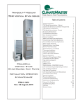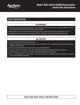
1
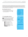
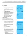
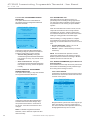
ATC32U02 iGate™ Communicating,
Programmable Thermostat
User Manual
97B0055N02
Rev.: 2/24/14
Table of Contents
Section
1.0
2.0
3.0
4.0
5.0
5.1
5.2
Title
Page
Menu Navigation Shortcuts
Operating Mode Selection
Temperature Adjustment
Fan Mode Selection
Humidity Level Adjustment
Main Menu Options Overview
Date and Time
Hold
3
3
4
4
5
6
7
7
Section
5.3
5.4
5.5
5.6
5.7
5.8
6.0
7.0
Title
Page
Program
Fan
Mode
Other Settings
Security Lockout
Night Setback
Service Needed
Revision History
9
9
9
10
14
14
15
16
This page was intentionally left blank.
AT C 3 2 U 0 2 C o m m u n i c a t i n g , P r o g r a m m a b l e T h e r m o s t a t - U s e r M a n u a l
R e v. : 2 4 F e b . , 2 0 1 4
ClimateMaster’s ATC32U** Communicating, Programmable Thermostat is the perfect compliment to your ClimateMaster Geothermal Heat Pump System and represents a significant advancement in thermostat communicating technology. For homeowners, the ATC32U** provides highly customizable climate control features designed to maximize comfort and reduce the
amount of energy consumed by your ClimateMaster Geothermal Heat Pump System. Please read the following instructions
carefully to maximize the comfort and cost-saving potential of your ClimateMaster Geothermal Heat Pump System and thanks
for choosing ClimateMaster for your home comfort needs.
Menu Navigation Shortcuts
1. From any other screen than the home screen, hold down
the left arrow button ( ) to return to the home screen.
2. From the home screen, hold the left arrow button ( ) to
go to the System Status screen.
1.0 Operating Mode Selection
To set the Operating Mode of your thermostat, navigate to the
MODE user option on the Home Screen using the left/right
arrow buttons and press the center button. The Operating
Mode Menu shows the possible Operating Modes with the
currently active Operating Mode highlighted. Use the up/
down arrow buttons to select the desired Mode for use and
press the center button to save your selection. The following
Modes are available:
• Off (default): No equipment operation
• Auto: Thermostat automatically controls the
equipment to run either heating or cooling
depending on the setpoints.
• Cool: Thermostat controls cooling equipment
depending on Cooling setpoint
• Heat: Thermostat controls heating equipment
depending on Heating setpoint
• Emergency Heat: Thermostat controls auxiliary
heat. No compressor operation.
SYSTEM STATUS
LT1 TEMP
38.1
LT2 TEMP
79.9
COMP DISCHARGE 157.7
HOT WATER EWT
121.5
LEAVING AIR
75.1
LEAVING WATER
73.3
ENTERING WATER
78.5
ECM BLOWER RPM
550
ECM TARGET CFM
800
ECM BLWR STATIC
0.5
PUMP WATTS
140
FLOW RATE GPM
7.4
PUMP SPEED
60%
PREVIOUS
10/13/11
8:27 AM
FAN AUTO
RH 41%
HUMID ON
°
69
AUTO
SETPOINT
HEAT 62
COOL 82
RH TEMP MODE FAN MENU
OPERATING MODE MENU
OFF
AUTO
COOL
HEAT
EMERGENCY HEAT
CHANGE MODE
PREVIOUS
SAVE
3
AT C 3 2 U 0 2 C o m m u n i c a t i n g , P r o g r a m m a b l e T h e r m o s t a t - U s e r M a n u a l
R e v. : 2 4 F e b . , 2 0 1 4
2.0 Temperature Adjustment
To adjust the temperature on the thermostat, use the left/
right arrow buttons to select the TEMP user option on the
Home Screen and then press the center button or press the
up or down arrow key. The Temperature Adjustment Display
appears and shows either one (in Heat, Cool, or Emergency
Heat modes) or both (in Auto mode) temperature setpoints.
Adjust the setpoints using the up/down arrow buttons.
Navigate between setpoints using the left/right arrow buttons.
Press the center button to save changes.
• Heat Setpoint (default 60°F): options: 55°F to
Maximum Heating Setpoint Limit (section 5.6.8)
• Cool Setpoint (default 80°F): options: Minimum
Cooling Setpoint Limit (section 5.6.8) to 95°F
NOTE 1: The thermostat must be in any mode other than
OFF (section 2) to adjust temperature setpoint(s).
NOTE 2: The thermostat forces a 2°F “dead-band” between
the Heating and Cooling setpoints. While adjusting
the Heating setpoint, the Cooling setpoint may be
automatically increased to enforce a 2°F “deadband”. Likewise, while adjusting the Cooling
setpoint, the Heating setpoint may be automatically
reduced to enforce a 2°F “dead-band”.
10/13/11
8:25 AM
FAN AUTO
RH 41%
HUMID ON
°
68
AUTO
SETPOINT
HEAT 62
COOL 82
RH TEMP MODE FAN MENU
HOLD THIS
TEMPERATURE
UNTIL 5:00 PM
HEAT
COOL
°
70
74°
CHANGE SET TEMP
SAVE
PREVIOUS
NOTE 3: In programmable mode, the TEMP option provides
the ability to temporarily modify setpoint(s) until
the start time of the next program schedule event.
While in non-programmable mode, the TEMP
option provides the ability to modify the setpoint(s).
NOTE 4: When the up/down arrow buttons are engaged, the
last mode of operation is highlighted.
3.0 Fan Mode Selection
10/13/11
FAN AUTO
RH 40%
To adjust the Fan Mode on your thermostat, use the left/
right arrow buttons to select the FAN user option from the
Home Screen and then press the center button. The Fan
Menu shows up to 3 possible Fan Operating Modes with the
currently active Fan Operating Mode highlighted. Use the
up/down arrow buttons to select the desired Fan Mode and
press the center button to save your selection. You may
choose from the following Fan Modes:
• Auto (default): Fan only runs with a call for
heating/cooling
• Continuous On: Fan runs continuously with or
without a call for heating/cooling
• Programmed Fan (in Programmable Mode): Fan
runs per Program Schedule settings (reference
section 5.3).
8:27 AM
°
69
OFF
RH TEMP MODE FAN MENU
FAN MENU
AUTO
CONTINUOUS ON
PROGRAMMED FAN
HEAT
SELECT OPTION
PREVIOUS
4
Geothermal Heat Pump Systems
SAVE
AT C 3 2 U 0 2 C o m m u n i c a t i n g , P r o g r a m m a b l e T h e r m o s t a t - U s e r M a n u a l
R e v. : 2 4 F e b . , 2 0 1 4
4.0 Humidity Level Adjustment
NOTE 1: The thermostat must be configured by installer for
humidity control to access the humidity setpoint(s).
To adjust the Relative Humidity level on your thermostat,
use the left/right arrow buttons to select the RH user
option on the Home Screen and then press the center
button. The Humidity Control screen shows either one (with
Humidification or Dehumidification enabled alone) or both
(with BOTH enabled) humidity setpoints. Adjust the setpoints
using the up/down arrow buttons. Press the center button to
save changes.
• Humidification Setpoint (default 40%): options:
10% to 45% (in 5% increments)
NOTE:
Humidifier must be installed to set humidification
setpoint.
• Dehumidification Setpoint (default 60%):
options: 45% to 80% (in 5% increments)
NOTE 2: The thermostat forces a 10% “dead-band” between
the Humidification and Dehumidification setpoints.
While adjusting the Dehumidification setpoint,
the Humidification setpoint may be automatically
reduced to enforce a 10% “dead-band”. However,
the Dehumidification setpoint will not be
automatically increased to enforce a 10% “deadband” while adjusting the Humidification setpoint.
The maximum range for the Humidification setpoint
may be limited by the Dehumidification setpoint.
10/12/11
5:22 PM
FAN AUTO
HUMID ON
RH 38%
°
70
AUTO
SETPOINT
HEAT 70
COOL 78
RH TEMP MODE FAN MENU
HUMIDITY CONTROL
42%
HUMIDITY
HUMIDITY SETTING 40%
DEHUMID SETTING
60%
NOTE 3: If an outdoor sensor is present, the Humidification
setpoint will be calculated automatically for optimal
comfort.
5
AT C 3 2 U 0 2 C o m m u n i c a t i n g , P r o g r a m m a b l e T h e r m o s t a t - U s e r M a n u a l
R e v. : 2 4 F e b . , 2 0 1 4
5.0 Main Menu Options Overview
MENU
5.1 DATE AND TIME
5.1.1 AUTO DAYLIGHT SAVING
5.1.2 SET DATE AND TIME
5.1.3 DISPLAY DATE AND TIME
5.2
5.3
5.4
5.5
5.6
HOLD
PROGRAM
FAN
MODE
SETTINGS
5.6.1 SCREEN SETTINGS
5.6.1.1 Fahrenheit or Celsius
5.6.1.2 12 or 24 Hour Clock
5.6.1.3 Language
5.6.1.4 Contrast
5.6.1.5 Backlight On Time
5.6.1.6 Date Display
5.6.2 OFFSETS
5.6.2.1 Temperature Offset
5.6.2.2 Humidity Offset
5.6.3 AUTO CHANGEOVER TIME
5.6.4 PROGRAM SETTINGS
5.6.4.1 Programming Option
5.6.4.2 Smart Recovery
5.6.4.3 Events Per Day
5.6.4.4 Demand Reduction
NOTE: All menu options may not be present depending on
your thermostat’s configuration.
5.6.5 INTERMITTENT FAN
5.6.6 SERVICE INFORMATION
5.6.7.1 Fault Status
5.6.7.3 Clear Fault History
5.6.7.4 System Status
5.6.7 DEMAND REDUCTION
5.7 SECURITY LOCKOUT
5.8 NIGHT SETBACK
5.8.1 SETPOINTS
5.8.2 OVERRIDE
5.8.3 DEMAND REDUCTION
5.8.4 FAN OPERATION
5.8.5 DEHUMIDIFICATION
NOTE: All of the following menu functions are
accessed by scrolling to the MENU user option
on the Home Screen and then pressing the
center button.
Access main menu by selecting MENU on the main
screen.
5.1 DATE AND TIME
The thermostat can be programmed for daylight savings,
date and time, and to display date and time on the main
screen.
6
Geothermal Heat Pump Systems
AT C 3 2 U 0 2 C o m m u n i c a t i n g , P r o g r a m m a b l e T h e r m o s t a t - U s e r M a n u a l
R e v. : 2 4 F e b . , 2 0 1 4
5.0 Main Menu
10/13/11
8:27 AM
FAN AUTO
5.1.1 AUTO DAYLIGHT SAVING
When enabled, the thermostat automatically adjusts
the time for daylight savings time.
5.1.2 SET DATE AND TIME
To set the current date and time, use the up/down
arrow buttons. Press the center button to save
changes.
5.1.3 DISPLAY DATE AND TIME
When enabled, the thermostat will display the date and
time (section 5.1.2) on the top line of the Main screen.
NOTE: When the thermostat is configured for non
programmable mode by installer the Display Date and
Time setting defaults to NO.
Section 5.2 and 5.3 will not be displayed if the
thermostat is set as “non-programmable” in installer
settings (contact your dealer to change).
RH 40%
°
69
OFF
RH TEMP MODE FAN MENU
MAIN MENU
SET DATE AND TIME
HOLD
PROGRAM
FAN
MODE
SETTINGS
SECURITY LOCKOUT
5.2 HOLD (Temperature)
The thermostat can be programmed to hold the temperature
and override the program schedule for a set time. The
thermostat can accommodate any hold schedule, whether the
temperature hold is desired for a few hours or a few weeks.
NOTE 1: The thermostat must be in any mode other than
OFF (section 2) to set a vacation/permanent hold.
NOTE 2: The thermostat must be configured for
programmable mode by installer) to access the
Hold modes.
5.2.1 VACATION (Hold)
This feature can suspend the program schedule by
using specified heating/cooling setpoints for extended
periods of time.
MAIN MENU
SET DATE AND TIME
HOLD
PROGRAM
FAN
MODE
SETTINGS
SECURITY LOCKOUT
5.2.1.1 HOLD TEMPERATURE
Set the Vacation Hold heating/cooling setpoints.
The Vacation Hold Temperature Display Mode
shows either one (in Heat, Cool, or Emergency
Heat modes) or both (in Auto mode) temperature
setpoints. Adjust the setpoints using the up/down
arrow buttons. Navigate between setpoints using
the left/right arrow buttons. Press the center
button to save changes.
• Heat Setpoint (default current Heat Setpoint):
valid range: 55°F to Maximum Heating Setpoint
Limit (section 5.6.8)
• Cool Setpoint (default current Cool Setpoint):
valid range: Minimum Cooling Setpoint Limit
(section 5.6.8) to 95°F
HOLD MENU
VACATION
PERMANENT
SELECT OPTION
PREVIOUS
7
AT C 3 2 U 0 2 C o m m u n i c a t i n g , P r o g r a m m a b l e T h e r m o s t a t - U s e r M a n u a l
R e v. : 2 4 F e b . , 2 0 1 4
NOTE: The thermostat forces a 2°F “dead-band”
between the Heating and Cooling setpoints. While
adjusting the Heating setpoint, the Cooling setpoint
may be automatically increased to enforce a 2°F
“dead-band”. Likewise, while adjusting the Cooling
setpoint, the Heating setpoint may be automatically
reduced to enforce a 2°F “dead-band”.
HOLD THIS
TEMPERATURE
UNTIL 5:00 PM
HEAT
COOL
74
70°
°
CHANGE SET TEMP
SAVE
PREVIOUS
5.2.1.2 HOLD TIME
Set the Vacation Hold time period.
Adjust the date using the up/down arrow buttons.
Press the center button to save changes.
• Date (default current Date): in 1 day
increments
• Time (default current Time): in 10 minute
increments
HOLD THIS
TEMPERATURE
5.2.2 PERMANENT
The thermostat can be programmed to hold the
temperature and override the program schedule
permanently.
UNTIL 5:00 PM
HEAT
The Permanent Hold Display Mode shows either one
(in Heat, Cool, or Emergency Heat modes) or both
(in Auto mode) temperature setpoints. Adjust the
setpoints using the up/down arrow buttons. Navigate
between setpoints using the left/right arrow buttons.
Press the center button to save changes.
• Heat Setpoint (default current Heat
Setpoint): valid range: 55°F – Maximum
Heating Setpoint Limit (section 5.6.8)
• Cool Setpoint (default current Cool
Setpoint): valid range: Minimum Cooling
Setpoint Limit (section 5.6.8) – 95°F
°
70
5.3.1 CREATE / EDIT SCHEDULE
This function allows you to set the time, heat setting,
cool setting, and fan operation for each program
schedule event of the day.
8
74°
CHANGE SET TEMP
SAVE
PREVIOUS
NOTE: The thermostat forces a 2°F “dead-band”
between the Heating and Cooling setpoints. While
adjusting the Heating setpoint, the Cooling setpoint
may be automatically increased to enforce a 2°F
“dead-band”. Likewise, while adjusting the Cooling
setpoint, the Heating setpoint may be automatically
reduced to enforce a 2°F “dead-band”.
5.3 PROGRAM
The Program Display Mode includes options to copy
schedules as well as create/edit schedules for individual days
or schedules for groups of days.
COOL
MAIN MENU
SET DATE AND TIME
HOLD
PROGRAM
FAN
MODE
SETTINGS
SECURITY LOCKOUT
Geothermal Heat Pump Systems
AT C 3 2 U 0 2 C o m m u n i c a t i n g , P r o g r a m m a b l e T h e r m o s t a t - U s e r M a n u a l
R e v. : 2 4 F e b . , 2 0 1 4
NOTE 1: To adjust the number of program schedule
events per day, reference the Program Settings
(section 5.6.5.2).
Default daily program schedule for 4-event schedule
(see NOTE 1):
PROGRAM MENU
COPY
MONDAY
TUESDAY
WEDNESDAY
THURSDAY
FRIDAY
SATURDAY
Event
Heat
Cool
Fan (see NOTE 2)
Wake - 6:00A
70ºF
78ºF
Auto
EVERY DAY
Leave - 8:00A
62ºF
82ºF
Auto
WEEKENDS
Return - 5:00P
70ºF
78ºF
Auto
Sleep - 10:00P
62ºF
82ºF
Auto
SELECT OPTION
PREVIOUS
Default daily program schedule for residential 2-event
schedule (see NOTE 1):
Event
Heat
Cool
Fan (see NOTE 2)
Day - 6:00A
70ºF
78ºF
Auto
Night - 10:00P
62ºF
82ºF
Auto
Default daily program schedule for business 2-event
schedule (see NOTE 1):
Event
Heat
Cool
Fan (see NOTE 2)
Active - 6:00A
70ºF
78ºF
Auto
Idle - 6:00P
62ºF
82ºF
Auto
NOTE 2: The Fan Mode (section 3) must be set to
Programmed Fan to access the fan operation for each
schedule event setting.
WEEKDAYS
MONDAY
WAKE HEAT COOL FAN
6:00 A 70
78 AUTO
LEAVE
8:00A
62
82 AUTO
RETURN
5:00P
70
78 AUTO
SLEEP
10:00P
62
82 AUTO
SAVE
PREVIOUS
PROGRAM MENU
COPY
TUESDAY
THURSDAY
SATURDAY
5.3.2 COPY
Copy can be used to copy one day’s program
schedule to another day or multiple other days.
SUNDAY
EVERY DAY
WEEKENDS
MONDAY
WEDNESDAY
FRIDAY
SUNDAY
WEEKDAYS
SELECT OPTION
PREVIOUS
5.4 FAN (Fan Mode)
Refer to Section 3.
5.5 MODE (Operating Mode)
Refer to Section 2.
5.6 OTHER SETTINGS
5.6.1 SCREEN SETTINGS
Adjust the Screen settings using the up/down arrow
buttons. Press the center button to save changes.
• Fahrenheit or Celsius (default Fahrenheit):
adjusts the temperature scale
• 12 or 24 Hour Clock (default 12 Hour Clock):
adjusts the clock format
• Language (default English)
• Contrast (default 4): adjusts the screen contrast
- options: 1 to 15
9
AT C 3 2 U 0 2 C o m m u n i c a t i n g , P r o g r a m m a b l e T h e r m o s t a t - U s e r M a n u a l
R e v. : 2 4 F e b . , 2 0 1 4
• Backlight On Time (default 30 seconds): After
a button press, the backlight stays on for the
selected amount of time - options: 30 to 120
seconds, ON (in 30 second increments)
• Date Display (default MM/DD/YY): adjusts the
date format
5.6.2 OFFSETS
Not recommended for user access. Contact your
dealer for changes.
•
•
•
Programmable (default) – enables 7-day
programming
Non-Programmable – disables 7-day programming
Night Setback – enables night setback
programming
NOTE: When the thermostat is configured for nonprogrammable mode, the Display Date and Time
setting defaults to NO.
PROGRAM SETTINGS
5.6.2.1 TEMPERATURE OFFSET
If you find that the temperature displayed on the
thermostat does not accurately represent the room
temperature where the thermostat is located, this
offset function compensates for the difference.
The thermostat will apply an offset between what
temperature the thermostat is measuring versus the
temperature that is displayed.
PROGRAMMING OPTION
SMART RECOVERY
EVENTS PER DAY
DEMAND REDUCTION
TEMPERATURE OFFSET
The Temperature Offset function allows for
calibration of the temperature sensor.
Adjust the Temperature Offset settings using the
up/down arrow buttons. Press the center button to
save changes.
• Indoor Temperature (default 0°F): options:
-5°F to +5°F (in 1°F increments)
• Remote Temperature (default 0°F): options:
-5°F to +5°F (in 1°F increments)
• Outdoor Temperature (default 0°F): options:
-5°F to +5°F (in 1°F increments)
5.6.2.2
HUMIDITY OFFSET
If you find that the Humidity level displayed on
the thermostat does not accurately represent the
Humidity level of the room in which the thermostat is
located, use the Humidity Offset function to calibrate
the humidity sensor.
Adjust the Humidity Offset setting using the up/
down arrow buttons. Press the center button to
save changes.
•
Indoor Humidity (default 0%): options:
-10% to +10% (in 1% increments)
5.6.3 AUTO CHANGEOVER TIME
Not recommended for user access. Contact your
dealer for changes.
5.6.4 PROGRAM SETTINGS
Set additional system parameters related to program
scheduling and system operation.
5.6.4.1 PROGRAMMING OPTION
Adjust the Programming options using the up/down
arrow buttons. Press the center button to save
changes.
10
SELECT OPTION
PREVIOUS
5.6.4.2 SMART RECOVERY
Smart recovery is a feature designed to save
energy by gradually adjusting temperatures. When
it is time for a program schedule temperature
change, smart recovery begins working in
advance, turning the system on and off as needed
to slowly adjust the indoor temperature so that
it reaches the program temperature setpoints at
the time you set. Rather than waiting to start the
equipment until the program time has occurred.
Adjust the Smart Recovery setting using the up/
down arrow buttons. Press the center button to
save changes.
• Events Per Day (default On): options: ON,
OFF
NOTE 1: The thermostat must be configured for
programmable mode by installer to access the
Smart Recovery setting.
NOTE 2: Auxiliary heat will not be used during
Smart Recovery.
5.6.4.3 EVENTS PER DAY
NOTE: The thermostat must be configured for
programmable mode by installer to access the
Events per Day setting.
Events Per Day sets the number of program
schedule events for each day. An event is a period
of time scheduled with a certain heat setpoint, cool
setpoint, and fan mode.
Geothermal Heat Pump Systems
AT C 3 2 U 0 2 C o m m u n i c a t i n g , P r o g r a m m a b l e T h e r m o s t a t - U s e r M a n u a l
R e v. : 2 4 F e b . , 2 0 1 4
Adjust the Events Per Day setting using the up/
down arrow buttons. Press the center button to
save changes.
• Events Per Day (default 4 events): options:
4-Residential, 2-Residential, 2-Business
5.6.4.4 PROGRAMMED DEMAND REDUCTION
Programmed Demand Reduction is a feature
designed to reduce your electric load during
preselected time periods in which peak utility rates
are high. You can program your thermostat to
reduce the electric load by limiting operation or
capacity during the high utility rate time period that
you specify for each day of the week.
While the Programmed Demand Reduction mode
is active, the thermostat outputs will be limited
by the Programmed Demand Reduction option
selected below.
NOTE: The thermostat must be configured for
programmable mode by installer to access the
Programmed Demand Reduction settings.
•
No 2nd Stage Compressor: During the
scheduled Programmed Demand Reduction
time (section 5.6.5.5.4), the compressor is
limited to only part load (1st stage) operation
and auxiliary heat is turned off, regardless of
system demand.
NOTE 1: The thermostat must be configured for
auxiliary heat by installer to access the Demand
Reduction NO AUXILIARY HEAT option.
NOTE 2: The thermostat must be configured
for Multistage by installer to access the Demand
Reduction NO 2nd STAGE COMP option.
5.6.4.4.2 Climadry™ - PROGRAMMED
DEMAND REDUCTION
This option allows for the customization
of Climadry™ (Dehumidification, optional)
operation during the Programmed Demand
Reduction schedule.
PROGRAMMED DEMAND
REDUCTION OPERATION
FOR CLIMADRY
5.6.4.4.1 PROGRAMMED DEMAND
REDUCTION MODE
Through Programmed Demand Reduction
Mode, you can set the unit’s limited operation
during the Programmed Demand Reduction
schedule.
ALLOW CLIMADRY
Adjust the Programmed Demand Reduction
Mode settings using the up/down arrow buttons.
Press the center button to save changes.
SELECT OPTION
PREVIOUS
DEMAND REDUCTION
OPTION FOR
PROGRAM OPERATION
NO DEMAND REDUCTION
NO AUXILIARY HEAT
NO 2ND STAGE COMP
SELECT OPTION
PREVIOUS
•
•
SAVE
No Demand Reduction (default): During
the scheduled Programmed Demand
Reduction time (section 5.6.5.5.4), the
system operates normally based on the
setpoints.
No Auxiliary Heat: During the scheduled
Programmed Demand Reduction time
(section 5.6.5.5.4), auxiliary heat will not
be activated, regardless of the heating
demand.
WHEN DEMAND REDUCTION
IS ACTIVE
SUSPEND CLIMADRY
SAVE
Adjust the Programmed Demand Reduction
Climadry™ settings using the up/down arrow
buttons. Press the center button to save
changes.
• Suspend Climadry™ (default): During the
scheduled Programmed Demand Reduction
time (section 5.6.5.5.4), Climadry™ is
turned off, regardless of the dehumidification
demand.
• Allow Climadry: During the scheduled
Programmed Demand Reduction time
(section 5.6.5.5.4), Climadry™ will operate
normally.
NOTE: The thermostat must be configured
for humidity control by installer and the DXM2
must be configured for Climadry™ operation to
access Demand Reduction Climadry™ settings.
11
AT C 3 2 U 0 2 C o m m u n i c a t i n g , P r o g r a m m a b l e T h e r m o s t a t - U s e r M a n u a l
R e v. : 2 4 F e b . , 2 0 1 4
5.6.4.4.3 FAN - PROGRAMMED DEMAND
REDUCTION
This option allows for the customization of
fan settings during the Programmed Demand
Reduction schedule.
PROGRAMMED DEMAND
REDUCTION FAN
OPERATION
WHEN DEMAND REDUCTION
IS ACTIVE
AUTO FAN ONLY
ALLOW CONSTANT FAN
SELECT OPTION
PREVIOUS
SAVE
Adjust the Programmed Demand Reduction
Fan settings using the up/down arrow buttons.
Press the center button to save changes.
• Auto Fan Only (default): During the
scheduled Programmed Demand Reduction
time (section 5.6.5.5.4), only auto fan mode
is allowed.
• Allow Continuous Fan: During the
scheduled Programmed Demand Reduction
time (section 5.6.5.5.4), the fan will operate
normally.
5.6.4.4.4 SCHEDULE - PROGRAMMED
DEMAND REDUCTION
This option allows setting a 7-day time schedule
for Programmed Demand Reduction.
5.6.5 INTERMITTENT FAN
Intermittent Fan function allows the fan to run
periodically when the heating/cooling equipment is
off. Many times this functionality is used to improve
the performance of air cleaning or special filtration
systems.
When the Intermittent Fan function is active, the fan
output will be activated for the currently selected
Intermittent Fan On Time, and then operate using
the selected Intermittent Fan Off and On times until a
heating or cooling operation is activated again.
After the heating or cooling operation is complete,
the intermittent fan operation will resume with the
beginning of a new Intermittent Fan On Time on the ¼
hour.
• On Time (default Off): options: Off, 5 to 20
minutes (in 5 minute increments)
• Off Time: options: 5 to 90 minutes (in 5 minute
increments)
NOTE: This intermittent fan operation can also
improve the performance of air cleaning or special
filtration systems that locate the cleaning or filtration
media at the return air side of the fan.
5.6.6 SERVICE INFORMATION (System Status and
Fault Information)
These additional screens help the service personnel to
have a better understanding of what problems might
be occurring before arriving for service.
5.6.6.1 FAULT STATUS
Fault Status mode displays the active fault code as
well as the five most recent stored fault codes that
occurred on the system.
PROGRAMMED DEMAND
REDUCTION SCHEDULE
FAULT STAUS
ACTIVE FAULT
NO FAULT
DEMAND REDUCTION
START
END
TIME
TIME
MON
8:00A
4:00P
TUE
8:00A
4:00P
WED
8:00A
4:00P
THU
8:00A
4:00P
FRI
8:00A
4:00P
SAT
12:00P
12:00P
SUN
12:00P
12:00P
SAVE
PREVIOUS
Adjust the Programmed Demand Reduction
Schedule start and end time settings using
the up/down arrow buttons in increments of
10 minutes. Press the center button to save
changes.
LAST 5 FAULTS
NO
REDUCTION
LT1DEMAND
LOW WATER
TEMP
NO FAULT
NO FAULT
NO FAULT
NO FAULT
PREVIOUS
Navigate between system fault codes using the up/
down arrow buttons. Press the center button to
view more information about potential reasons why
the highlighted fault may have occurred.
NOTE: To disable Programmed Demand
Reduction, set the Start time equal to the End
time for that day.
12
DETAILS
Geothermal Heat Pump Systems
AT C 3 2 U 0 2 C o m m u n i c a t i n g , P r o g r a m m a b l e T h e r m o s t a t - U s e r M a n u a l
R e v. : 2 4 F e b . , 2 0 1 4
FAULT CODE E2
HIGH REFRIG PRESSURE
DIRTY FILTER - HEATING
NO DEMAND REDUCTION
LOW AIR FLOW - HEATING
LOW WATER FLOW - CLG
OVERCHARGED
BAD PRESSURE SWITCH
PREVIOUS
5.6.6.2 CLEAR FAULT HISTORY
Clear Fault History will clear all fault codes stored
in the thermostat.
5.6.6.3 SYSTEM STATUS
System Status mode allows the user to view the
status of all temperature sensor readings as well
as the operational status of the blower and pump.
NOTE 1: If any temperature reading is out of the
valid range, N/A will be displayed.
NOTE 2: If the connected communicating control
is not configured for Pump by installer or no
valid pump information is communicated by the
connected control, N/A will be displayed.
SYSTEM STATUS
LT1 TEMP
LT2 TEMP
COMP DISCHARGE
HOT WATER EWT
LEAVING AIR
LEAVING WATER
ENTERING WATER
ECM BLOWER RPM
ECM TARGET CFM
ECM BLWR STATIC
PUMP WATTS
FLOW RATE GPM
PUMP SPEED
PREVIOUS
38.1
79.9
157.7
121.5
75.1
73.3
78.5
550
800
0.5
140
7.4
60%
5.6.7 DEMAND REDUCTION - External Sensor Input
Demand Reduction is used to reduce the electric
load while peak utility rates are high. While the
Demand Reduction mode is active, the thermostat
will implement load reduction by limiting operation or
capacity. The thermostat outputs will be limited by
the Demand Reduction option selected below (section
5.6.8.1).
NOTE: The thermostat must be configured for
Demand Reduction by installer to access Demand
Reduction settings.
5.6.7.1 DEMAND REDUCTION MODE
Through Demand Reduction Mode, you can set the
unit’s limited operation while Demand Reduction is
active.
Adjust the Demand Reduction Mode settings using
the up/down arrow buttons. Press the center
button to save changes.
• No Auxiliary Heat (default): While the
assigned Demand Reduction input is active,
auxiliary heat will not be activated regardless of
the heating demand.
• No 2nd Stage Compressor: While the
assigned Demand Reduction input is active,
the compressor is limited to only part load (1st
stage) operation and auxiliary heat is turned off
regardless of system demand.
• No Operation (default – if either setting is
not present): While the assigned Demand
Reduction input is active, the thermostat
outputs will not be activated for heating or
cooling regardless of the heating or cooling
demand.
NOTE 1: The thermostat must be configured for
auxiliary heat by installer to access the Demand
Reduction NO AUXILIARY HEAT option.
NOTE 2: The thermostat must be configured
for Multistage by installer to access the Demand
Reduction NO 2nd STAGE COMP option.
5.6.7.2 Climadry™ - DEMAND REDUCTION
This option allows for the customization of
Climadry™ (Dehumidification, optional) operation
while Demand Reduction is active.
Adjust the Demand Reduction Climadry™ settings
using the up/down arrow buttons. Press the center
button to save changes.
• Suspend Climadry™ (default): While the
assigned Demand Reduction input is active,
Climadry™ is turned off, regardless of the
dehumidificaiton demand.
• Allow Climadry: While the assigned Demand
Reduction input is active, Climadry™ will
operate normally.
NOTE: The thermostat must be configured for
humidity control by installer and the DXM2 must
be configured for Climadry™ operation to access
Demand Reduction Climadry™ settings.
5.6.7.3 FAN - DEMAND REDUCTION
This option allows for the customization of fan
settings while Demand Reduction is active.
Adjust the Demand Reduction Fan settings using
the up/down arrow buttons. Press the center
button to save changes.
13
AT C 3 2 U 0 2 C o m m u n i c a t i n g , P r o g r a m m a b l e T h e r m o s t a t - U s e r M a n u a l
R e v. : 2 4 F e b . , 2 0 1 4
•
•
Auto Fan Only (default): While the assigned
Demand Reduction input is active, the fan
output will not be activated unless the heat
pump is in 1st or 2nd stage operation or
auxiliary heat mode is active.
Allow Continuous Fan: While the assigned
Demand Reduction input is active, the fan
output will operate normally.
5.7 SECURITY LOCKOUT
The Security Lockout function allows you to lockout
thermostat display, requiring a password to make changes.
Adjust the four-digit Security Pin using the up/down arrow
buttons. Navigate between digits using the left/right arrow
buttons. Press the center button to save changes.
• Temp Adjust Only: while locked, thermostat will still
allow temperature adjustment
• Total Keypad Lockout: while locked, thermostat will not
allow any changes
5.8.1 NIGHT SETBACK SETPOINTS
Adjust the Night Setback setpoints using the up/down
arrow buttons. Navigate between Night Setback
setpoints using the left/right arrow buttons. Press the
center button to save changes.
• Heat Setpoint (default 60°F): options: 55°F to
Maximum Heating Setpoint Limit (section 5.6.8)
• Cool Setpoint (default 80°F): options: Minimum
Cooling Setpoint Limit (section 5.6.8) to 95°F
NOTE: The thermostat forces a 2°F “dead-band”
between the Night Setback Heating and Cooling
setpoints. While adjusting the Night Setback Heating
setpoint, the Night Setback Cooling setpoint may be
automatically increased to enforce a 2°F “dead-band”.
Likewise, while adjusting the Night Setback Cooling
setpoint, the Night Setback Heating setpoint may be
automatically reduced to enforce a 2°F “dead-band”.
5.8.2 NIGHT SETBACK OVERRIDE
While the Night Setback mode is active, the alternate
Night Setback setpoints can be temporarily overridden,
by using the normal temperature adjustment screen.
If the heating and cooling setpoints are adjusted while
Night Setback is active, these temporary setpoints will
remain active for the current Night Setback Override
time, unless they are adjusted again, or the Night
Setback mode is de-activated.
MAIN MENU
SET DATE AND TIME
HOLD
PROGRAM
FAN
MODE
SETTINGS
SECURITY LOCKOUT
Adjust the Night Setback Override setting using the
up/down arrow buttons. Press the center button to
save changes.
• Night Setback Override (default 2 hours):
options: 1 to 8 hours (in 15 minute increments)
SECURITY LOCKOUT
5.8.3 NIGHT SETBACK DEMAND REDUCTION
Through Night Setback Demand Reduction Mode,
you can set the unit’s limited operation while Night
Setback is active.
TEMP ADJUST ONLY
TOTAL KEYPAD LOCKOUT
SELECT OPTION
PREVIOUS
SAVE
5.8
NIGHT SETBACK
Under Night Setback mode, the thermostat will operate using
alternate Night Setback heating and cooling setpoints, fan
mode, and humidification and dehumidification setpoints. Night
Setback is activated by an input signal at the unit control board
to reduce the electric load while the building is unoccupied.
NOTE: While the Night Setback mode is active, the screen
backlight will be red when ON.
14
Adjust the Night Setback Demand Reduction Mode
settings using the up/down arrow buttons. Press the
center button to save changes.
• No Demand Reduction (default): While the Night
Setback input and the assigned Demand Reduction
input is active, the thermostat outputs will operate
normally based on the night setback setpoints.
• No Auxiliary Heat: While the Night Setback
input and the assigned Demand Reduction input
is active, auxiliary heat will not be activated,
regardless of the heating demand.
• No 2nd Stage Compressor: While the Night
Setback input and the assigned Demand Reduction
input is active, the second stage heat pump output
will not be activated regardless of the heating or
cooling demand, and auxiliary heat will not be
activated, regardless of the heating demand.
Geothermal Heat Pump Systems
AT C 3 2 U 0 2 C o m m u n i c a t i n g , P r o g r a m m a b l e T h e r m o s t a t - U s e r M a n u a l
R e v. : 2 4 F e b . , 2 0 1 4
NOTE 1: The thermostat must be configured for
auxiliary heat to access the Demand Reduction NO
AUXILIARY HEAT option.
NOTE 2 : The thermostat must be configured for
Multistage to access the Demand Reduction NO 2nd
STAGE COMP option.
5.8.4 NIGHT SETBACK FAN OPERATION
This option allows for the customization of fan settings
while Night Setback is active.
Adjust the Night Setback Fan settings using the up/
down arrow buttons. Press the center button to save
changes.
• Auto Operation Only (default): While the Night
Setback input is active, the fan output will not be
activated unless Y1 or W is active.
• Fan Same As Occupied: While the Night Setback
input is active, the fan output will operate normally.
5.8.5 NIGHT SETBACK DEHUMIDIFICATION
This option allows for the customization of humidity
control while Night Setback is active.
Adjust the Night Setback Dehumidification settings
using the up/down arrow buttons. Press the center
button to save changes.
• On: While the Night Setback input is active, the
dehumidification output will operate normally.
• Off (default): While the Night Setback input is
active, the dehumidification output will not be
activated, regardless of the dehumidification
demand.
5.8.5.1 NIGHT SETBACK HUMIDITY CONTROL
If the Night Setback Dehumidification Mode is set
to ON, the thermostat will prompt for Night Setback
Humidity Setpoints. Adjust the Night Setback
Humidity setpoints using the up/down arrow
buttons. Press the center button to save changes.
• Humidification Setpoint (default 40%):
options: 10% to 45% (in 5% increments)
• Dehumidification Setpoint (default 60%):
options: 45% to 80% (in 5% increments)
6.0 Service Needed
If the unit is not operating or not operating optimally, the
thermostat will display the ‘Service Needed’ screen.
SERVICE
NEEDED
PRESS ANY BUTTON FOR
MORE INFORMATION
The next screen will display the model and serial number of
your ClimateMaster unit, the phone number of your installing
contractor, and the fault code and a description of the fault
that triggered the Service Needed screen.
SERVICE
NEEDED
PHONE CONTRACTOR
CONTRACTOR NAME
CONTRACTOR PHONE
BRAND NAME
CLIMATEMASTER
MODEL NUMBER
123456789
SERIAL NUMBER
987654321
E# - FAULT NAME
RESET
Refer to section 5.6.7 to get more information regarding
possible causes of the fault condition and current system
performance.
15
AT C 3 2 U 0 2 C o m m u n i c a t i n g , P r o g r a m m a b l e T h e r m o s t a t - U s e r M a n u a l
R e v. : 2 4 F e b . , 2 0 1 4
7.0 Revision History
Page #
24 Feb., 14
All
2 July, 12
Various
Fault Status and System Status Information Added
2 July, 12
Various
Demand Reduction Screen Images Added
8 May, 12
All
Description
Updated from ATC32U01 to U02
First Published
R
AI
BR
I
HE
AT P U M P S
A
TO
NE
WATER
TO
IFIED TO ARI A
RT
S
C
CE
NG WITH
LYI
MP
O
IR
MANUFACT
UR
ER
Date
IS
ST
AND
3
ARD 1
-1
R
O
25
6
ISO 9001:2008
Certified
Quality: First & Always
7300 S.W. 44th Street
Oklahoma City, OK 73179
Phone: 405-745-6000
*97B0055N02*
Fax: 405-745-6058
climatemaster.com
97B0055N02
ClimateMaster works continually to improve its products. As a result, the design and specifications of each product at the time for order may be
changed without notice and may not be as described herein. Please contact ClimateMaster’s Customer Service Department at 1-405-745-6000
for specific information on the current design and specifications. Statements and other information contained herein are not express warranties and do not form the basis of any bargain between the parties, but are merely ClimateMaster’s opinion or commendation of its products.
The management system governing the manufacture of ClimateMaster’s products is ISO 9001:2000 certified.
© ClimateMaster, Inc. 2012
16
Geothermal Heat Pump Systems
Rev.: 24 Feb., 2014