1
SERVICE MANUAL
ERA & EBD SERIES ELECTRIC
FRYERS WITH KLEENSCREEN
PLUS® FILTRATION SYSTEMS
MODEL
2ER50AF KLEENSCREEN
FRYER BATTERY
ML
MODEL
ML
1ER50A
136730
2XER50AF
136747
1E50BD
136730
2XE50BDF
136747
1ER50AF
136799
2XER85AF
136748
1E50BDF
136799
2XE85BDF
136748
1ER85A
136740
3ER50AF
136743
1E85BD
136740
3E50BDF
136743
1ER85AF
136802
3ER85AF
136744
1E85BDF
136802
3E85BDF
136744
2ER50AF
136741
4ER50AF
136745
2E50BDF
136741
4E50BDF
136745
2ER85AF
136742
4ER85AF
136746
2E85BDF
136742
4E85BDF
136746
This Manual is prepared for the use of trained Vulcan Service
Technicians and should not be used by those not properly qualified.
This manual is not intended to be all encompassing. If you have not
attended a Vulcan Service School for this product, you should read,
in its entirety, the repair procedure you wish to perform to
determine if you have the necessary tools, instruments and skills
required to perform the procedure. Procedures for which you do not
have the necessary tools, instruments and skills should be
performed by a trained Vulcan Service Technician.
The reproduction, transfer, sale or other use of this Manual, without
the express written consent of Vulcan, is prohibited.
This manual has been provided to you by ITW Food Equipment
Group LLC ("ITW FEG") without charge and remains the property
of ITW FEG, and by accepting this manual you agree that you will
return it to ITW FEG promptly upon its request for such return at
any time in the future.
For additional information on Vulcan-Hart Company or to locate an authorized parts
and service provider in your area, visit our website at www.vulcanhart.com.
A product of VULCAN-HART
LOUISVILLE, KY 40201-0696
F25385 (May 2010)
ERA & EBD SERIES ELECTRIC FRYERS
TABLE OF CONTENTS
GENERAL . . . . . . . . . . . . . . . . . . . . . . . . . . . . . . . . . . . . . . . . . . . . . . . . . . . . . . . . . . . . . . . . . . . . . . . . . . . . . . . .
Introduction . . . . . . . . . . . . . . . . . . . . . . . . . . . . . . . . . . . . . . . . . . . . . . . . . . . . . . . . . . . . . . . . . . . . . . . . . . . .
Single Floor Model Fryers . . . . . . . . . . . . . . . . . . . . . . . . . . . . . . . . . . . . . . . . . . . . . . . . . . . . . . . . . . . . . . . .
Kleenscreen Filtration System . . . . . . . . . . . . . . . . . . . . . . . . . . . . . . . . . . . . . . . . . . . . . . . . . . . . . . . . . . . . .
Specifications . . . . . . . . . . . . . . . . . . . . . . . . . . . . . . . . . . . . . . . . . . . . . . . . . . . . . . . . . . . . . . . . . . . . . . . . . .
Tools . . . . . . . . . . . . . . . . . . . . . . . . . . . . . . . . . . . . . . . . . . . . . . . . . . . . . . . . . . . . . . . . . . . . . . . . . . . . . . . . .
3
3
3
4
4
4
REMOVAL AND REPLACEMENT OF PARTS . . . . . . . . . . . . . . . . . . . . . . . . . . . . . . . . . . . . . . . . . . . . . . . . . . . . 5
Covers and Panels . . . . . . . . . . . . . . . . . . . . . . . . . . . . . . . . . . . . . . . . . . . . . . . . . . . . . . . . . . . . . . . . . . . . . . 5
Cooking Controls . . . . . . . . . . . . . . . . . . . . . . . . . . . . . . . . . . . . . . . . . . . . . . . . . . . . . . . . . . . . . . . . . . . . . . . 6
Discard Valve Switch (Kleenscreen Fryers Only) . . . . . . . . . . . . . . . . . . . . . . . . . . . . . . . . . . . . . . . . . . . . . . . 6
Temperature Probe . . . . . . . . . . . . . . . . . . . . . . . . . . . . . . . . . . . . . . . . . . . . . . . . . . . . . . . . . . . . . . . . . . . . . 6
High Limit Thermostat . . . . . . . . . . . . . . . . . . . . . . . . . . . . . . . . . . . . . . . . . . . . . . . . . . . . . . . . . . . . . . . . . . . 7
Electrical Components . . . . . . . . . . . . . . . . . . . . . . . . . . . . . . . . . . . . . . . . . . . . . . . . . . . . . . . . . . . . . . . . . . . 8
Circuit Breaker/ Supply Box Components . . . . . . . . . . . . . . . . . . . . . . . . . . . . . . . . . . . . . . . . . . . . . . . . . . . . 8
Fill Solenoid Valve (Kleenscreen Fryers Only) . . . . . . . . . . . . . . . . . . . . . . . . . . . . . . . . . . . . . . . . . . . . . . . . . 9
Heating Elements . . . . . . . . . . . . . . . . . . . . . . . . . . . . . . . . . . . . . . . . . . . . . . . . . . . . . . . . . . . . . . . . . . . . . . . 9
Lift Assist Springs . . . . . . . . . . . . . . . . . . . . . . . . . . . . . . . . . . . . . . . . . . . . . . . . . . . . . . . . . . . . . . . . . . . . . . 10
Tilt Switch . . . . . . . . . . . . . . . . . . . . . . . . . . . . . . . . . . . . . . . . . . . . . . . . . . . . . . . . . . . . . . . . . . . . . . . . . . . . 11
Pump and Motor (Kleenscreen Fryers Only) . . . . . . . . . . . . . . . . . . . . . . . . . . . . . . . . . . . . . . . . . . . . . . . . . 12
SERVICE PROCEDURES AND ADJUSTMENTS . . . . . . . . . . . . . . . . . . . . . . . . . . . . . . . . . . . . . . . . . . . . . . . . .
Temperature Probe Test . . . . . . . . . . . . . . . . . . . . . . . . . . . . . . . . . . . . . . . . . . . . . . . . . . . . . . . . . . . . . . . .
Cooking Control Calibration . . . . . . . . . . . . . . . . . . . . . . . . . . . . . . . . . . . . . . . . . . . . . . . . . . . . . . . . . . . . . .
Lift Assist Spring Adjustment . . . . . . . . . . . . . . . . . . . . . . . . . . . . . . . . . . . . . . . . . . . . . . . . . . . . . . . . . . . . .
Heating Element Test . . . . . . . . . . . . . . . . . . . . . . . . . . . . . . . . . . . . . . . . . . . . . . . . . . . . . . . . . . . . . . . . . . .
13
13
14
14
16
ELECTRICAL OPERATION . . . . . . . . . . . . . . . . . . . . . . . . . . . . . . . . . . . . . . . . . . . . . . . . . . . . . . . . . . . . . . . . . .
Component Function . . . . . . . . . . . . . . . . . . . . . . . . . . . . . . . . . . . . . . . . . . . . . . . . . . . . . . . . . . . . . . . . . . .
Component Location . . . . . . . . . . . . . . . . . . . . . . . . . . . . . . . . . . . . . . . . . . . . . . . . . . . . . . . . . . . . . . . . . . .
Sequence of Operation . . . . . . . . . . . . . . . . . . . . . . . . . . . . . . . . . . . . . . . . . . . . . . . . . . . . . . . . . . . . . . . . . .
Filtering System . . . . . . . . . . . . . . . . . . . . . . . . . . . . . . . . . . . . . . . . . . . . . . . . . . . . . . . . . . . . . . . . . . .
Schematic Diagrams . . . . . . . . . . . . . . . . . . . . . . . . . . . . . . . . . . . . . . . . . . . . . . . . . . . . . . . . . . . . . . . . . . .
208V & 240V Fryers Shown With KleenScreen Filtration System . . . . . . . . . . . . . . . . . . . . . . . . . . . . .
480V Fryers Shown With KleenScreen Filtration System . . . . . . . . . . . . . . . . . . . . . . . . . . . . . . . . . . . .
Wiring Diagrams . . . . . . . . . . . . . . . . . . . . . . . . . . . . . . . . . . . . . . . . . . . . . . . . . . . . . . . . . . . . . . . . . . . . . . .
208V & 240V (14, 17 kW) Fryers Shown With KleenScreen Filtration System . . . . . . . . . . . . . . . . . . .
208V & 240V (24 kW) Fryers Shown With KleenScreen Filtration System . . . . . . . . . . . . . . . . . . . . . .
480V Fryers Shown With KleenScreen Filtration System . . . . . . . . . . . . . . . . . . . . . . . . . . . . . . . . . . . .
Frymate (Dump Station) . . . . . . . . . . . . . . . . . . . . . . . . . . . . . . . . . . . . . . . . . . . . . . . . . . . . . . . . . . . . .
17
17
19
20
20
22
22
23
24
24
26
28
30
TROUBLESHOOTING . . . . . . . . . . . . . . . . . . . . . . . . . . . . . . . . . . . . . . . . . . . . . . . . . . . . . . . . . . . . . . . . . . . . . .
All Models . . . . . . . . . . . . . . . . . . . . . . . . . . . . . . . . . . . . . . . . . . . . . . . . . . . . . . . . . . . . . . . . . . . . . . . . . . . .
Frymate (Dump Station) with Optional Heater . . . . . . . . . . . . . . . . . . . . . . . . . . . . . . . . . . . . . . . . . . . . . . . .
Kleenscreen Filtering System . . . . . . . . . . . . . . . . . . . . . . . . . . . . . . . . . . . . . . . . . . . . . . . . . . . . . . . . . . . . .
31
31
31
32
© VULCAN 2010
F25385 (May 2010)
Page 2 of 32
ERA & EBD SERIES ELECTRIC FRYERS - GENERAL
GENERAL
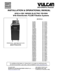
INTRODUCTION
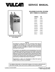
SINGLE FLOOR MODEL FRYERS
This Service Manual covers specific service
information related to the models listed on the front
cover. ERA and EBD series electric fryers come
equipped with behind-the-door solid state controls.
The features and operation of the cooking controls
are the same for both single floor model fryers and
Kleenscreen battery fryers. All pictures and
illustrations are of a 2ER50AF (17kW, 208V) unless
otherwise noted.
Fryers with the Filter-Ready option installed, use the
Mobile Filter. For service information related to the
Mobile filter refer to F24599 MOBILE FILTERS.
A GRO Frymate (dump station) can be configured in
a battery with fryers 15 1/2 inches or 21 inches in
width.
KILOWATT
EACH FRY TANK
FRYER WIDTH
(INCHES)
TOTAL SYSTEM
SHORTENING CAPACITY
(LBS)
EACH FRY TANK
1ER50A (1E50BD)
17
15.5
50
1ER50AF (1E50BDF)
17
15.5
50
1ER85A (1E85BD)
24
21.0
85
1ER85AF (1E85BDF)
24
21.0
85
2ER50AF (2E50BDF)
17
31.0
50
2ER85AF (2E85BDF)
24
42.0
85
2XER50AF (2XE50BDF)
17
31.0
50
2XER85AF (2XE85BDF)
24
42.0
85
3ER50AF (3E50BDF)
17
46.5
50
3ER85AF (3E85BDF)
24
63.0
85
4ER50AF (4E50BDF)
17
62.0
50
4ER85AF (4E85BDF)
24
84.0
85
Model
Page 3 of 32
F25385 (May 2010)
ERA & EBD SERIES ELECTRIC FRYERS - GENERAL
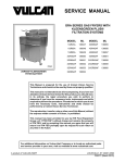
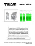
KLEENSCREEN FILTRATION
SYSTEM
The Kleenscreen filtration system is integrated into
the ERA & EBD Series fryer battery. The filter is
housed in a pull-out drawer assembly at the base of
the fryer. The filtering components in the drawer
include a stainless steel filter tank, crumb-catch
basket and a dual element mesh filter screen. With
the filter drawer closed, a self-seating oil return line
provides the path to return the filtered shortening to
the fry tank.
This system is designed to provide a thorough and
easy method to filter the shortening.
Some of the benefits include:
•
On 208VAC and 240VAC models, a
transformer provides power for the fryer
controls and drawer filter system controls.
•
On 480VAC models, a 120VAC connection is
required for each fryer section.
TOOLS
Standard
•
Standard set of hand tools.
•
VOM with A/C current tester (any quality VOM
with a sensitivity of at least 20,000 ohms per
volt can be used).
•
Digital Temperature tester (thermocouple type).
Special
•
Self-contained system eliminating the use of
external filter equipment.
•
Field service grounding kit (available locally).
•
Paperless filtering system.
•
•
Easy to clean and low maintenance.
Burndy pin extraction tool RX2025 GE1;
Newark Electronics Catalog Number 16F6666.
Used for removing pin terminals on Burndy
connectors.
•
Clamp on type amp meter.
Kleenscreen fryer batteries are available in a
minimum of two and a maximum of four fryer
sections. The fryer size of each section is identical.
A GRO Frymate (dump station) can also be included
as one or more of the sections.
SPECIFICATIONS
MODEL
KW
AMPS - EACH FRYER
SECTION
PER
(3 PHASE/ 60HZ)*
FRYER
PER LINE
SECTION
ALL 50 LB
CAPACITY
FRYERS
ALL 85 LB
CAPACITY
FRYERS
NOTES:
208V
240V
480V
14
39
34
17
17
47
41
20
24
67
58
29
* Amperage values in the table are
nominal. Tolerance is +5/-10%.
Single Floor Model Fryers
•
208VAC, 240VAC or 480VAC (3 phase, 60HZ)
to power the heating elements.
Drawer Filter System
Separate electrical connections are required for
each section of the battery.
•
208VAC, 240VAC or 480VAC (3 phase, 60HZ)
to power the heating elements.
F25385 (May 2010)
Page 4 of 32
ERA & EBD SERIES ELECTRIC FRYERS - REMOVAL AND REPLACEMENT OF PARTS
REMOVAL AND REPLACEMENT OF PARTS
COVERS AND PANELS
Electrical Components Access Panel
1.
Remove screws at top of access panel and
lower panel.
2.
Lift from hinge then remove panel.
3.
Reverse procedure to install.
4.
Remove screws from the bottom of element
head assembly.
5.
Grasp heating elements and remove 2x4
lumber. Lift the elements and pull toward rear of
fryer. Head cover will separate from element
head base.
Element Head Cover
1.
Drain shortening from fry tank.
2.
Remove screws from rear of element head
assembly.
A.
Lower the heating elements and place
them in fry tank.
NOTE: Heating elements remain attached to
element head cover.
6.
3.
Reverse procedure to install.
Raise heating elements and place 2x4 lumber
under them for support.
Page 5 of 32
F25385 (May 2010)
ERA & EBD SERIES ELECTRIC FRYERS - REMOVAL AND REPLACEMENT OF PARTS
COOKING CONTROLS
1.
Open fryer section door(s).
2.
Remove electrical connection to cooking
controls.
3.
Remove screws securing controls.
4.
Remove cooking control cover.
5.
Disconnect lead wires from the component
being replaced then remove from control box.
DISCARD VALVE SWITCH
(KLEENSCREEN FRYERS ONLY)
1.
Open the door to the fryer section being
serviced.
2.
Disconnect lead wire connector.
3.
Remove switch mounting screws.
4.
Remove discard valve switch.
5.
Reverse procedure to install and check for
proper operation.
NOTE: Switches are not adjustable.
TEMPERATURE PROBE
Do not sharply bend and kink, or clamp
down on the capillary tube or damage may occur.
6.
1.
Raise heating elements.
2.
Remove clamps from temperature probe.
Reverse procedure to install and check for
proper operation.
F25385 (May 2010)
Page 6 of 32
ERA & EBD SERIES ELECTRIC FRYERS - REMOVAL AND REPLACEMENT OF PARTS
3.
Remove element head cover as outlined under
COVERS AND PANELS.
4.
Disconnect temperature probe lead wires.
5.
Remove temperature probe from the element
head.
6.
Reverse procedure to install.
2.
Loosen clamps securing capillary tube and bulb
to element.
3.
Remove element head cover as outlined under
COVERS AND PANELS.
4.
Remove high limit from mounting bracket.
5.
Disconnect high limit lead wires.
6.
Remove grommet from the element head
assembly.
7.
Remove the bulb, capillary tube and high limit
from the element head assembly.
8.
Reverse procedure to install.
NOTE: When installing, ensure grommet remains in
place when inserting temperature probe thru the
grommet in the element head.
7.
Check cooking control calibration as outlined in
COOKING CONTROL CALIBRATION under
SERVICE PROCEDURES AND
ADJUSTMENTS.
HIGH LIMIT THERMOSTAT
A.
Slide grommet onto capillary tube then
insert grommet into the capillary tube thru
hole in the element head.
B.
Move element lead wires clear of high limit
when installing.
Do not sharply bend and kink, or clamp
down on the capillary tube or damage may occur.
1.
Raise heating elements.
Page 7 of 32
F25385 (May 2010)
ERA & EBD SERIES ELECTRIC FRYERS - REMOVAL AND REPLACEMENT OF PARTS
ELECTRICAL COMPONENTS
1.
2.
CIRCUIT BREAKER/ SUPPLY
BOX COMPONENTS
Open electrical component access panel.
1.
Remove screw and circuit breaker/ supply box
cover.
2.
Disconnect lead wires then remove the
component being replaced.
Disconnect lead wires then remove the
component being replaced.
NOTE: Supply box will contain a circuit breaker on
24kW 208-240V units.
3.
Reverse procedure to install the replacement
component and check for proper operation.
3.
F25385 (May 2010)
Page 8 of 32
Reverse procedure to install the replacement
component and check for proper operation.
ERA & EBD SERIES ELECTRIC FRYERS - REMOVAL AND REPLACEMENT OF PARTS
B.
FILL SOLENOID VALVE
(KLEENSCREEN FRYERS ONLY)
1.
If replacing right heating element, remove
temperature probe clamps and position
temperature probe away from element.
Disconnect swivel pipe fitting at rear of fry tank.
NOTE: When installing high limit, route the capillary
tube and center the bulb between the clamps before
tightening.
2.
Disconnect fill solenoid valve lead wire
connector from below control panel.
3.
Remove screws (2) securing the solenoid valve
body flange to pipe tee then remove the
assembly from fryer.
A.
4.
2.
Remove element assembly clamps.
3.
Remove element head cover as outlined under
COVERS AND PANELS.
4.
Disconnect heating element lead wires.
Remove pipe fittings from solenoid valve
and install on replacement valve.
Reverse procedure to install and check for
proper operation.
HEATING ELEMENTS
Do not sharply bend and kink, or clamp
down on the capillary tube or damage may occur.
1.
NOTE: Each heating element assembly contains
three individual elements (six lead wire connections
total).
Raise heating elements.
A.
If replacing left heating element, loosen
high limit bulb and capillary tube clamps.
Remove high limit bulb and capillary tube
from clamps then position away from
element.
5.
Page 9 of 32
Remove screws from heating element mounting
bracket and remove heating element.
F25385 (May 2010)
ERA & EBD SERIES ELECTRIC FRYERS - REMOVAL AND REPLACEMENT OF PARTS
6.
Reverse procedure to install.
LIFT ASSIST SPRINGS
3.
Remove lift assist springs from the eye bolt
hooks.
4.
Remove lift assist springs from the hangers.
5.
To install springs:
NOTE: If one spring breaks, replace both springs.
1.
Raise heating elements and place 2x4 lumber
under them for support. Heating elements are
to remain upright.
2.
Loosen all eye bolt mounting nuts to release
tension on springs.
6.
F25385 (May 2010)
Page 10 of 32
A.
Attach spring hook to hanger thru rear
door opening.
B.
Attach spring hook to eye bolt and tighten
eye bolt mounting nut.
C.
Remove 2x4 lumber and lower heating
elements.
Adjust spring tension as outlined under LIFT
ASSIST SPRING ADJUSTMENT in SERVICE
PROCEDURES AND ADJUSTMENTS.
ERA & EBD SERIES ELECTRIC FRYERS - REMOVAL AND REPLACEMENT OF PARTS
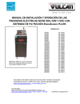
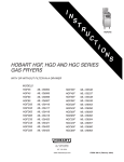
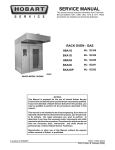
TILT SWITCH
1.
Remove element head cover as outlined under
COVERS AND PANELS.
2.
Lower heating elements.
3.
Disconnect lead wires from tilt switch.
4.
Remove tilt switch from element head.
REAR VIEW SHOWN, ELEMENTS LOWERED
FRONT VIEW SHOWN, ELEMENTS RAISED
5.
Reverse procedure to install and check for
proper operation.
Page 11 of 32
F25385 (May 2010)
ERA & EBD SERIES ELECTRIC FRYERS - REMOVAL AND REPLACEMENT OF PARTS
PUMP AND MOTOR
(KLEENSCREEN FRYERS ONLY)
1.
Drain filter tank of shortening.
2.
Open the fryer section doors above the filter
tank drawer.
3.
Pull filter drawer out, remove filter tank
assembly and push the tank support arms back
into place under the fryer.
4.
Remove splash guard from base frame.
5.
Disconnect pump motor lead wire connector.
6.
From underneath the fryer:
A.
7.
A.
8.
Disconnect flexible line fittings from pump.
Remove pump motor assembly from fryer.
F25385 (May 2010)
Page 12 of 32
Remove pipe fittings from the pump and
install on replacement pump.
Reverse procedure to install and check for
proper operation.
ERA & EBD SERIES ELECTRIC FRYERS - SERVICE PROCEDURES AND ADJUSTMENTS
SERVICE PROCEDURES AND ADJUSTMENTS
TEMPERATURE PROBE TEST
The temperature probe is an RTD (resistance
temperature device) of the thermistor type. As
temperature increases the resistance value
decreases.
Probe Fault
If a temperature probe fault occurs, red diagnostic
LED on back of control assembly (inside control box
cover) will flash. The heat demand outputs are
de-activated.
This will continue until the fault clears, power is
cycled or problem resolved.
A temperature probe fault can be caused by a lead
wire break or a lead short.
3.
To Check:
Test the probe using a VOM to measure
resistance. Connect the meter leads to pins 4 &
5 on the male connector.
A.
If the measured resistance values are
within the allowable range, the probe is
functioning properly. Reverse procedure to
install.
B.
If the measured resistance values are
outside the allowable range, install a
replacement probe and check for proper
operation.
Temperature (ºF)
Resistance (Ω)
1.
Turn power switch off.
77
90,000 - 110,000
2.
Disconnect cooking control connector.
212
5,016 - 6,130
275
1,804 - 2,204
300
1,254 - 1,534
350
646 - 790
392
391 - 478
Page 13 of 32
F25385 (May 2010)
ERA & EBD SERIES ELECTRIC FRYERS - SERVICE PROCEDURES AND ADJUSTMENTS
B.
COOKING CONTROL
CALIBRATION
1.
Verify condition of temperature probe as
outlined under TEMPERATURE PROBE TEST.
2.
Check the level of shortening in fry tank. The
level must be between the MIN & MAX fill lines
before proceeding.
3.
Place clamp on type amp meter around any
yellow lead wire of 2CON or 4CON.
If the average temperature reading is out of
tolerance, loosen set screw to remove
temperature knob and adjust calibration
potentiometer.
NOTE: Ensure that the shaft and knob position does
not change when loosening set screw and removing
temperature knob, as this could affect calibration.
1)
4.
Allow shortening to cool below 300EF.
5.
Place a thermocouple in the geometric center of
the fry tank one inch below the shortening
surface.
6.
Set the cooking control to 350EF and turn the
fryer on.
7.
Monitor the current as it cycles on and off.
a.
9.
NOTE: Stir shortening to eliminate any cold zones.
8.
A.
Allow heat to cycle three times to stabilize
shortening temperature.
B.
Record meter reading from thermocouple
when the current cycles off and on for at
least two complete heating cycles.
Calculate the average temperature by adding
the temperature reading when the heat goes off
to the temperature reading when the heat
comes on & divide this answer by 2.
[ Temp. (Heat off) + Temp. (Heat on) ] ÷ 2 = Average Temp.
Repeat the average temperature calculation for
up to three attempts. Allow the cooking control
to cycle at least two times between adjustments
before performing the calculation.
LIFT ASSIST SPRING
ADJUSTMENT
1.
Turn power switch off.
2.
Check spring tension:
The average temperature should be
350EF (± 5EF).
If the average temperature reading is
within tolerance, cooking control is properly
calibrated.
F25385 (May 2010)
If over 25E of adjustment is
necessary, replace cooking
control.
10. If calibration is unsuccessful, the cooking
control may be malfunctioning and cannot be
adjusted properly. Install a replacement cooking
control and check calibration.
Example: 360° + 340° ÷ 2 = 350°F.
A.
Adjust calibration potentiometer
clockwise to increase temperature,
and counterclockwise to decrease
temperature.
Page 14 of 32
A.
Raise heating elements to the full up
position. Elements should remain in place.
B.
Lower heating elements to the full down
position. Elements should remain in place.
C.
If the elements remain in place as
described, then no adjustment is
necessary. If the elements do not remain
in place, continue with procedure for
adjustment.
ERA & EBD SERIES ELECTRIC FRYERS - SERVICE PROCEDURES AND ADJUSTMENTS
3.
Lower heating elements to the down position.
4.
Loosen stop nut on all eye bolts.
5.
Adjust eye bolt mounting nuts as necessary,
but equally on all springs to achieve the best
spring tension to hold elements in place.
6.
Perform spring tension check (step 2 above).
7.
Repeat spring tension adjustment if necessary.
8.
Tighten stop nut on all eye bolts.
Page 15 of 32
F25385 (May 2010)
ERA & EBD SERIES ELECTRIC FRYERS - SERVICE PROCEDURES AND ADJUSTMENTS
C.
HEATING ELEMENT TEST
VOLTAGE
208
240
TOTAL
AMPS PER
OHMS PER
KW
ELEMENT
ELEMENT
14
11
18.4
17
13.5
15.5
24
19.2
10.8
14
9.6
25.1
17
11.6
20.5
24
16.7
14.4
14
4.8
100.1
17
5.8
82.3
21
7.3
65.8
24
8.3
57.6
5.
480
NOTES:
1. Values in the table are nominal.
Tolerance is +5/-10%.
2. Resistance values (ohms) are @ room
temperature.
3. There are 3 elements per firebar, 6
elements per tank.
1.
Remove element head cover as outlined under
COVERS AND PANELS in REMOVAL AND
REPLACEMENT OF PARTS.
Heating elements must remain submerged
in shortening while performing this test or damage
may occur.
2. Access heating element lead wire connections
at wire nuts.
3. Re-connect power, turn power switch on and
set cooking control to call for heat.
4. Measure voltage at heating element
connections and verify against data plate
voltage.
A. If voltage is incorrect, see ALL MODELS
under TROUBLESHOOTING.
B. If voltage is correct, check current draw
(amps) through the heating element lead
wires. See table for proper values.
NOTE: This method is preferred over a
resistance check when a clamp on type amp
meter is available.
1) If current draw is correct then heating
element is functioning properly.
2) If current draw is not correct, turn
power switch off and disconnect
power to the machine.
a. Install a replacement heating
element.
b. Proceed to last step.
F25385 (May 2010)
Page 16 of 32
If unable to check current draw, a
resistance check may indicate a
malfunctioning element. See table for
proper values.
1) Turn power switch off and disconnect
power to the machine.
2) Remove wire nuts from heating
element lead wire connections and
separate lead wires.
3) Check resistance (ohms).
Check for proper operation.
ERA & EBD SERIES ELECTRIC FRYERS - ELECTRICAL OPERATION
ELECTRICAL OPERATION
COMPONENT FUNCTION
FRYER CONTROLS
Cooking Control . . . . . . . . . . . . . . Monitors and evaluates input signals to the control: Activates heat output
signal to maintain shortening temperature; and activates filter output signal
to power the fill solenoid valve.
Transformer . . . . . . . . . . . . . . . . . Supplies 24VAC to the cooking control circuit. Transformer is energized
when power switch is turned on.
Power Switch . . . . . . . . . . . . . . . . Supplies power to control circuit for fryer operation and filtering.
Melt Select Switch . . . . . . . . . . . . Controls heating circuit operation during melt cycle based on type of
shortening being used (liquid/ solid).
High Limit Thermostat . . . . . . . . . Prevents the shortening from reaching temperatures over 450EF. (Manual
reset)
Temperature Probe . . . . . . . . . . . Senses temperature of shortening. Converts the temperature into a
resistance which is monitored by the cooking control. The probe is an RTD
(resistance temperature device) of the Thermistor type. As temperature
increases the resistance value decreases.
Drain Valve Interlock
Switch (DVI) . . . . . . . . . . . . . . . . . A magnetic reed switch mounted on the manual drain valve that supplies a
drain valve position signal (open/closed) to the cooking control. When drain
valve is open, the drain interlock input to the control is removed (magnetic
reed switch contacts open). This prevents heating elements from being
energized with the fry tank empty.
Tilt Switch . . . . . . . . . . . . . . . . . . . A magnetic reed switch (N.O.) mounted underneath the element head
assembly. Remove power from 1CON and 3CON to de-energize the
heating elements when the elements are raised.
1CON, 3CON and 2CON,
4CON Contactors . . . . . . . . . . . . . Supplies line voltage to heating elements.
Heating Elements . . . . . . . . . . . . . Produces heat that is transferred to the shortening.
R1 Heat Relay . . . . . . . . . . . . . . . . Supplies power to 2CON and 4CON contactor coils.
R2 Power Relay . . . . . . . . . . . . . . Supplies power to cooking control.
Page 17 of 32
F25385 (May 2010)
ERA & EBD SERIES ELECTRIC FRYERS - ELECTRICAL OPERATION
KLEENSCREEN FILTER CONTROLS
Fill Solenoid Valve . . . . . . . . . . . . When energized by filter switch, the solenoid valve opens to allow the flow of
shortening thru filtering system.
Pump Motor . . . . . . . . . . . . . . . . . Operates pump to circulate shortening through filtering system.
Start Switch . . . . . . . . . . . . . . . . . . Supplies start heating function to the temperature control at the beginning of
a cooking cycle or after the vat has been filled from the filter process.
Filter Switch . . . . . . . . . . . . . . . . . Energizes pump motor to filter the shortening when switch is closed (valve
handle extended). Filter power switch must be turned on.
Discard Valve Switch . . . . . . . . . . A magnetic reed switch mounted on the mechanical discard valve that
closes when discard valve handle is extended to discard the shortening.
Prevents R4 solenoid relay N.C. contacts from suppling power to the fill
solenoid valve when filter key is pressed.
R3 Filter Relay . . . . . . . . . . . . . . . . Supplies power to pump motor and solenoid.
R4 Solenoid Relay . . . . . . . . . . . . Removes power to solenoid if discard valve switch is operated.
F25385 (May 2010)
Page 18 of 32
ERA & EBD SERIES ELECTRIC FRYERS - ELECTRICAL OPERATION
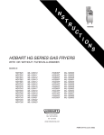
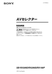
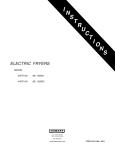
COMPONENT LOCATION
CONTROL PANEL COMPONENTS
COOKING CONTROL COMPONENTS
Page 19 of 32
F25385 (May 2010)
ERA & EBD SERIES ELECTRIC FRYERS - ELECTRICAL OPERATION
5.
SEQUENCE OF OPERATION
1.
Conditions.
A.
Fryer connected to correct supply voltage
and is properly grounded. Separate
connections are required for each section
of the battery.
1)
2.
C.
Power switch off.
D.
Shortening at proper level in fry tank and
below last set point temperature used.
E.
Cooking control is setup properly and
ready to use.
F.
Manual drain valve closed (drain valve
interlock switch N.O. is closed).
G.
Tilt switch contacts closed (N.O. - held
closed with heating elements lowered).
H.
High limit thermostat closed.
1CON and 3CON remain deenergized until the shortening
temperature drops below 460°F,
manual reset button is pressed and
start button is actuated.
Filtering System
The discard valve handle is connected to a
mechanical valve and switch assembly to route the
flow of shortening (electrically and mechanically) in
the filtering system.
Refer to Installation & Operation manual for specific
instructions on filtering.
1.
Conditions
A.
Fryer connected to correct supply voltage
and is properly grounded.
Supply voltage energizes:
B.
Power switch to the fryer section off.
1)
1CON and 3CON thru high limit
thermostat and tilt switch.
C.
Shortening between 300°F and 350°F.
D.
Filter drawer assembly installed properly.
2)
R2 power relay coil and R2 N.O.
contacts close.
E.
Filter power switch off.
3)
Cooking control thru DVI switch.
F.
Discard valve handle (yellow) retracted.
Turn power switch on.
1)
Press start momentary switch.
If shortening temperature is below set
point, J5 outputs 24VDC to R1 thru wire
56.
1)
R1 heat relay coil energized and R1
N.O. contacts close.
a.
2CON and 4CON are energized
and heating elements are
powered.
Shortening reaches set temperature.
A.
If shortening reaches 460EF, the high limit
thermostat opens, 1CON and 3CON are
de-energized and power is removed from
heating elements.
1)
Internal fryer circuit breaker ON (24kW,
208-240V units only).
A.
4.
A.
120/24VAC transformer energized.
B.
A.
3.
Cooking control cycles heat output on
shortening temperature until power switch is
turned off, heating elements are raised or a
high limit condition occurs.
Cooking control de-activates the heat
demand output (24VDC) at J5. With power
removed from J5, R1 is de-energized thru
wire 56.
1)
2.
Turn power switch on, to the fryer section to be
filtered.
3.
Set cooking control between 300°F (minimum)
and 350°F (maximum).
NOTE: Shortening should not be filtered outside of
this temperature range. At lower temperatures the
shortening is thicker which may increase filtering
time and place a greater load on the pump. At higher
shortening temperatures, the pump seal life is
decreased.
A.
2CON and 4CON are de-energized
and power is removed from heating
elements.
Allow shortening to cycle at set
temperature for approximately 10 minutes.
NOTE: If using solid shortening, once it has
melted, stir the shortening to eliminate any solid
shortening in cold zone of the fry tank.
4.
F25385 (May 2010)
Discard valve switch N.O. contacts
open. Mechanical discard valve
closed.
Page 20 of 32
Open the manual drain valve to the fryer
section in need of and drain the shortening into
filter tank. (Heat circuit will be disabled)
ERA & EBD SERIES ELECTRIC FRYERS - ELECTRICAL OPERATION
NOTE: If using solid shortening, allow hot
shortening to stand in filter tank for
approximately 6 minutes prior to filtering.
5.
shortening temperatures, the pump seal life is
decreased.
A.
Turn filter power switch on.
A.
R3 filter relay coil energized.
B.
R3 N.O. contacts close.
1)
NOTE: If using solid shortening, once it has
melted, stir the shortening to eliminate any solid
shortening in cold zone of the fry tank.
Power supplied to pump motor and fill
solenoid.
6.
Pump motor circulates shortening through filter
and solenoid to tank until power is removed.
7.
When filtering process is completed and the
tank is full, turn off filtering switch.
A.
Power is removed from pump motor and
solenoid closes.
NOTE: If using solid shortening, when all filtered
shortening is returned to the fry tank and filter power
switch is off, open the filter drawer approximately
one inch. Allow the remaining shortening in the line
to drain into the filter tank to prevent possible
clogging after the shortening cools and solidifies.
Close the filter drawer when complete.
8.
To restart the cooking process, press the start
button.
4.
The discard valve handle is connected to a
mechanical valve and switch assembly to route the
flow of shortening (electrically and mechanically) out
discard hose.
Refer to Installation & Operation manual for specific
instructions on draining.
Conditions
A.
Fryer connected to correct supply voltage
and is properly grounded.
B.
Power switch to the fryer section off.
C.
Shortening between 300°F and 350°F.
D.
Filter drawer assembly installed properly.
E.
Filter power switch off.
F.
Discard valve handle (yellow) retracted.
1)
Open the manual drain valve to the fryer
section in need of discarding and drain the
shortening into filter tank. (Heat circuit will be
disabled)
NOTE: If using solid shortening, allow hot
shortening to stand in filter tank for
approximately 6 minutes prior to discarding.
5.
Connect discard hose. Place other end of
discard hose in appropriately-sized receptacle.
6.
Pull out discard handle.
A.
Discard switch N.O. contacts close.
B.
R4 solenoid relay coil energized.
1)
7.
Discarding Shortening
1.
Allow shortening to cycle at set
temperature for approximately 10 minutes.
Turn filter power switch on.
A.
R3 filter relay coil energized.
B.
R3 N.O. contacts close.
1)
8.
R4 N.C. contacts open.
Power supplied to pump motor.
Pump motor circulates shortening out discard
hose and into receptacle.
If discard receptacle is not large enough to
hold entire shortening amount, turn filter switch off to
stop pump motor. Empty receptacle and resume
discard operation by turning filter switch on.
9.
When discard process is complete, turn off filter
switch.
A.
Power is removed from pump motor.
10. Push in discard handle.
Discard valve switch N.O. contacts
open. Mechanical discard valve
closed.
2.
Turn power switch on, to the fryer section to be
drained.
3.
Set cooking control between 300°F (minimum)
and 350°F (maximum).
NOTE: Shortening should not be drained outside of
this temperature range. At lower temperatures the
shortening is thicker which may increase draining
time and place a greater load on the pump. At higher
Page 21 of 32
F25385 (May 2010)
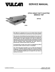
ERA & EBD SERIES ELECTRIC FRYERS - ELECTRICAL OPERATION
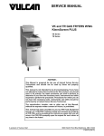
SCHEMATIC DIAGRAMS
208V & 240V Fryers Shown With KleenScreen Filtration System
F25385 (May 2010)
Page 22 of 32
ERA & EBD SERIES ELECTRIC FRYERS - ELECTRICAL OPERATION
480V Fryers Shown With KleenScreen Filtration System
Page 23 of 32
F25385 (May 2010)
ERA & EBD SERIES ELECTRIC FRYERS - ELECTRICAL OPERATION
WIRING DIAGRAMS
208V & 240V (14, 17 kW) Fryers Shown With KleenScreen Filtration System
F25385 (May 2010)
Page 24 of 32
ERA & EBD SERIES ELECTRIC FRYERS - ELECTRICAL OPERATION
Page 25 of 32
F25385 (May 2010)
ERA & EBD SERIES ELECTRIC FRYERS - ELECTRICAL OPERATION
208V & 240V (24 kW) Fryers Shown With KleenScreen Filtration System
F25385 (May 2010)
Page 26 of 32
ERA & EBD SERIES ELECTRIC FRYERS - ELECTRICAL OPERATION
Page 27 of 32
F25385 (May 2010)
ERA & EBD SERIES ELECTRIC FRYERS - ELECTRICAL OPERATION
480V Fryers Shown With KleenScreen Filtration System
F25385 (May 2010)
Page 28 of 32
ERA & EBD SERIES ELECTRIC FRYERS - ELECTRICAL OPERATION
Page 29 of 32
F25385 (May 2010)
ERA & EBD SERIES ELECTRIC FRYERS - ELECTRICAL OPERATION
Frymate (Dump Station)
F25385 (May 2010)
Page 30 of 32
ERA & EBD SERIES ELECTRIC FRYERS - TROUBLESHOOTING
TROUBLESHOOTING
ALL MODELS
SYMPTOMS
Fryer does not heat, but voltage IS present
between J2 and J9.
POSSIBLE CAUSES
1.
2.
3.
4.
5.
6.
Tilt switch covered with debris or malfunction (heating
elements are lowered).
High limit thermostat open.
Contactor(s) malfunction.
Cooking control malfunction (no output from terminal J5).
R1 heat relay malfunction.
Interconnecting wiring malfunction.
Fryer does not heat, voltage NOT present
between J2 and J9.
1.
2.
3.
4.
5.
6.
7.
Check main power to unit.
Internal circuit breaker OFF (24kW, 208-240V units only).
Power switch off or malfunction.
Transformer inoperative.
R2 power relay malfunction.
Drain valve switch open or switch malfunction.
Interconnecting wiring malfunction.
Excessive time to melt solid shortening
(more than 45 minutes).
1.
2.
3.
4.
Melt cycle timing incorrect.
Incorrect supply voltage.
Temperature probe malfunction.
Cooking control malfunction.
Excessive or low heat.
1.
2.
3.
4.
5.
6.
Incorrect supply voltage.
Temperature probe malfunction.
Contactor(s) malfunction.
R1 heat relay malfunction.
Heating element malfunction (low heat).
Cooking control malfunction.
Intermittent problems.
1.
2.
High ambient temperatures.
Wiring connections loose.
FRYMATE (DUMP STATION)
WITH OPTIONAL HEATER
SYMPTOM
No heat.
POSSIBLE CAUSES
1.
2.
3.
4.
Unplugged.
Power switch off or inoperative.
Main circuit breaker off or open.
Malfunctioning heater assembly.
Page 31 of 32
F25385 (May 2010)
ERA & EBD SERIES ELECTRIC FRYERS - TROUBLESHOOTING
KLEENSCREEN FILTERING
SYSTEM
SYMPTOM
POSSIBLE CAUSES
Shortening not filtering, pump motor is
energized.
1. Filter screen plugged.
2. Clog in filter system lines.
NOTE: If using solid shortening, when all filtered shortening
is returned to the fry tank and filter power switch is off, open
the filter drawer approximately one inch. Allow the remaining
shortening in the line to drain into the filter tank to prevent
possible clogging after the shortening cools and solidifies.
Close the filter drawer when complete.
3. Shortening below 300°F to thick.
4. Fill solenoid valve malfunction.
5. Interconnecting wiring malfunction.
6. Pump is inoperative.
Shortening not discarding, pump motor
energized.
1. Filter screen plugged.
2. Clog in filter system lines.
NOTE: If using solid shortening, when all filtered shortening
is returned to the fry tank and filter power switch is off, open
the filter drawer approximately one inch. Allow the remaining
shortening in the line to drain into the filter tank to prevent
possible clogging after the shortening cools and solidifies.
Close the filter drawer when complete.
3. Shortening below 300°F to thick.
4. Discard valve switch malfunction (N.O. contacts not
closing to energize R3 filter relay coil).
5. R3 fill relay malfunction (contacts remain closed).
NOTE: The fill solenoid valve should not be energized
during discard operation so that shortening will flow thru
manual discard valve only.
6. Discard valve mechanical malfunction.
7. Discard hose connection not fully engaged.
8. Pump is inoperative.
Pump motor is not energized to circulate
shortening thru filtering system.
1.
2.
3.
4.
5.
Filter switch on cooking controls not turned on.
Pump needs reset. (Reset button located on pump)
R3 filter relay malfunction.
Interconnecting wiring malfunction.
Pump motor inoperative.
Pump motor is not energized to discard
shortening.
1.
2.
3.
4.
5.
6.
Filter switch on cooking controls not turned on.
Pump needs reset. (Reset button located on pump)
Discard handle (yellow) not extended.
R3 filter relay malfunction.
Interconnecting wiring malfunction.
Pump motor inoperative.
F25385 (May 2010)
Printed in U.S.A.